

Nortec GH, GH 100, GH 200, GH 300, GH 400 Maintenance Manual
GH Series
Gas-fired Humidifier
Version D
Installation, User &
Maintenance Guide
FOR YOUR SAFETY:
Do not store or use gasoline or other flammable vapors and liquids in the vicinity of this
or any other appliance.
WHAT TO DO IF YOU SMELL GAS:
Do not try to light any appliance.
Do not touch any electrical switch; do not use any telephone in your building.
Immediately call your gas supplier from a neighbor’s telephone.
Follow the gas supplier’s instructions. If you can not reach your gas supplier, call the fire
department.
WARNING:
Improper installation, adjustment, alteration, service or maintenance can cause injury or
property damage. Refer to this manual. For assistance or additional information consult
a qualified installer, service agency, or the gas supplier.
WARNING:
If the information in this manual is not followed exactly, a fire or explosion may result
causing property damage, personal injury or loss of life.
IMPORTANT: Read and save this guide for future
reference. This guide to be left with equipment owner.
Form #02-272 150-3230 rev. A

Table Of Contents
GENERAL 1
- WARNING ................................................1
- RECEIVING & UNPACKING EQUIPMENT................................1
- GENERAL SPECIFICATIONS ......................................1
- MODEL DESIGNATION .........................................1
INSTALLATION 1
- LOCATING AND MOUNTING ......................................3
- GAS PIPING ...............................................5
- AIR MANIFOLD/CONNECTOR HOSE INSTALLATION FOR DIRECT VENT ..............6
- PROCEDURE:............................................6
- INTAKE AIR DUCT ............................................7
- TERMINAL LOCATION ..........................................7
- VENTING .................................................7
- STANDARD UNIT ........................................8
- DIRECT VENT UNIT ......................................8
- ADDITIONAL REQUIREMENTS WHEN VENTING THROUGH A SIDEWALL ...........8
- ELECTRICAL ...............................................9
- PRIMARY WIRING .........................................9
- LOW VOLTAGE CONTROL WIRING ...............................9
- CONTROL INSTALLATION .......................................10
- OUTDOOR ENCLOSURE HEATER SETTING .............................10
- BLOWER PACKS ............................................10
- STEAM DISTRIBUTORS FOR DUCTED APPLICATIONS .......................10
- PLUMBING ...............................................12
- FILL WATER SUPPLY LINE ....................................12
- DRAIN LINE ............................................13
- DRAIN WATER COOLER SUPPLY LINE .............................13
- STEAM LINE ............................................14
- WATER TRAP ...........................................15
- CONDENSATE RETURN LINES FOR STEAM DISTRIBUTORS .................15
OPERATION 16
- WATER LEVEL CONTROL .......................................16
- B AND P MODELS .........................................16
- MC MODEL ............................................16
- DRAIN WATER COOLER OPERATION ................................16
- START UP PROCEDURE .......................................17

- FILLING THE SYSTEM ......................................17
- TESTING THE IGNITION SAFETY SHUT-OFF ..........................17
- PRE-PURGE OF GAS VALVE AND MANIFOLD..........................17
- SEQUENCE OF OPERATION .....................................18
- BLOWDOWN CALIBRATION ......................................18
- DRAIN RATE AND BLOWDOWN VOLUME .............................18
- MANUAL STEAM OUTPUT ADJUSTMENT ..............................18
- B MODELS .............................................18
- GHMC DISPLAY OPERATION .....................................18
- SAFETY INSTRUCTIONS........................................19
MAINTENANCE 19
- DRAINING THE TANK .........................................19
- CLEANING THE STAINLESS STEEL TANK & FLOAT CHAMBER ..................19
- COMBUSTION BLOWER ........................................19
- BURNER ................................................20
- BURNER REMOVAL/INSPECTION ................................20
- ADJUSTMENTS/REPLACEMENTS OF COMPONENTS........................20
- GAS VALVE REPLACEMENT ...................................20
- HOT SURFACE IGNITER REPLACEMENT ............................20
- IGNITION MODULE REPLACEMENT ...............................20
- TRANSFORMER REPLACEMENT ................................20
- AIR SWITCH REPLACEMENT...................................21
- DRAIN PUMP REPLACEMENT ..................................21
- COMBUSTION AIR BLOWER REPLACEMENT ..........................21
- TANK REPLACEMENT ......................................21
- HEAT EXCHANGER REPLACEMENT...............................22
- SERVICING THE UNIT .........................................23
- FAULT CONDITIONS ..........................................23
- B AND P MODELS .........................................23
- MC MODELS ............................................23
- SERVICE CHECKS ...........................................23
- FLAME SENSOR..........................................23
- IGNITER CHECK..........................................24
- GAS VALVE SETTING .......................................24
- TROUBLESHOOTING GUIDE .....................................25
- MANDATORY MAINTENANCE SCHEDULE ..............................26
- START-UP AND INSPECTION .....................................27
- VENTING MANUFACTURER ......................................28
- EXTERNAL CONTROLS WIRING CONNECTIONS ..........................29
- GH B/P WIRING DIAGRAM .......................................30
- GH STAND ASSEMBLY.........................................31

- GH ENCLOSURE PHYSICAL DATA ..................................32
- GH ENCLOSURE HEATER INSTALLATION INSTRUCTIONS ....................33
- REPLACEMENT PARTS ......................................34-37
- MAINTENANCE CHART ........................................38
GENERAL
GENERAL SPECIFICATIONS
WARNING
Improper installation, adjustment, alteration,
·
service, maintenance, or use can cause carbon
monoxide poisoning, an explosion, fire, electrical
shock, or other conditions which may cause
personal injury or property damage. Consult a
qualified installer, service agency, local gas
supplier, or your distributor or branch for
information or assistance. The qualified installer
or agency must use only factory authorized and
listed kits or accessories when modifying this
product. A failure to follow this warning can
cause electrical shock, fire, personal injury, or
death.
Should overheating occur, or the gas fail to shut
·
off, shut off the manual gas valve to the appliance
before shutting off the electrical supply.
Do not use this appliance if any part has been
·
under water. Immediately call a qualified service
technician to inspect the appliance and to replace
any part of the control system and any gas
control which has been under water.
This installation guide has been designed to
provide assistance when installing, mounting, and
sizing a GH Series humidifier. Actual on site
application may vary. Consult Technical Services or
your local NORTEC representative.
The NORTEC GH Series humidifier is a
completely new patented design based on leading
edge technology. The GH is designed to provide
clean steam humidification at an economical price.
All GH models are available for normal altitude
(0-2000 ft elevation) or for high altitude (2000-4500 ft
elevation) applications.
GHMC models are also available with enclosure
for mounting outside when space is not available. The
unit will ship completely installed inside the outdoor
enclosure ready for field connection. The enclosure
will protect the unit from wind, sun and precipitation.
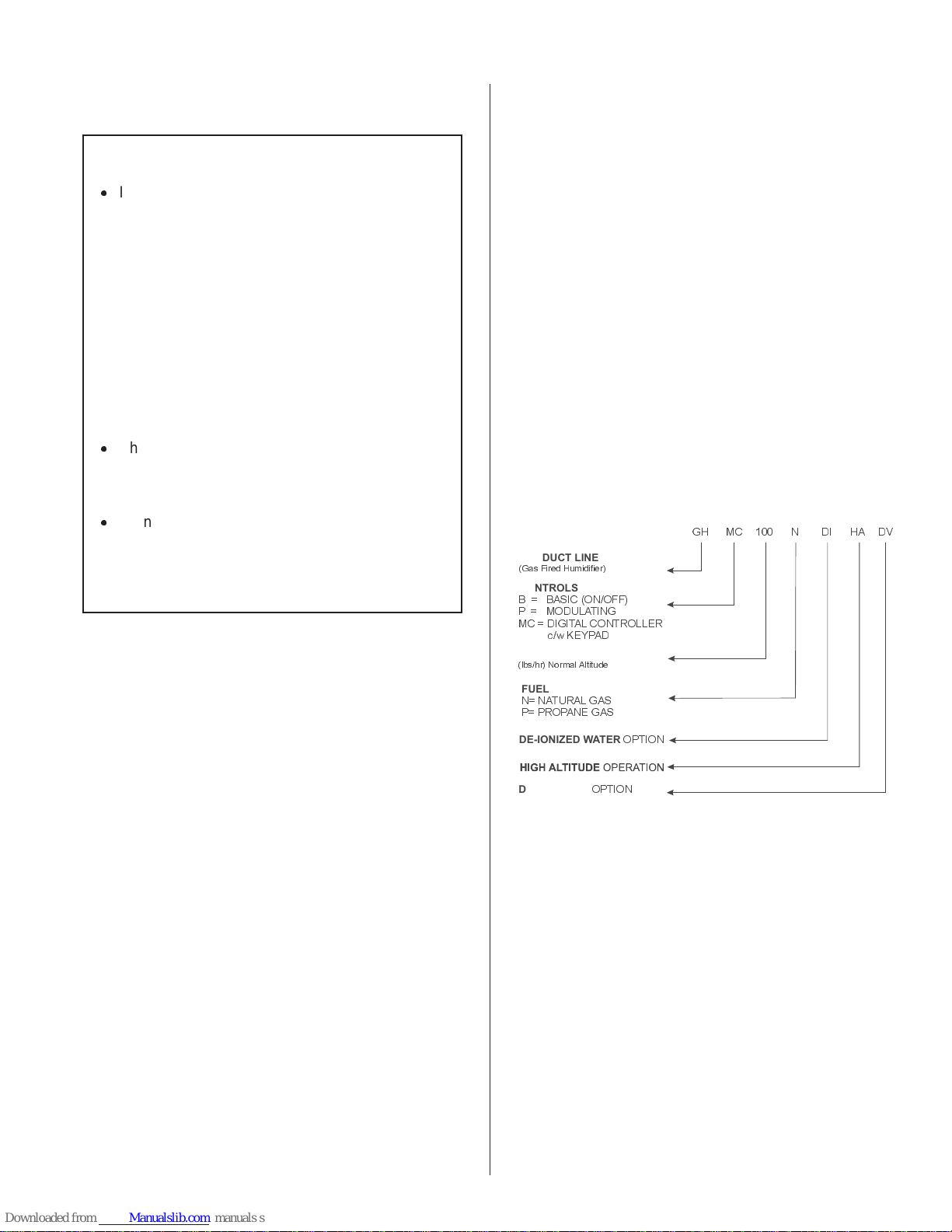
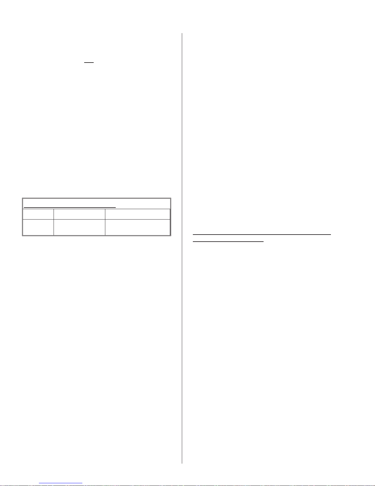
MODEL DESIGNATION
The unit specification label indicates the model of
gas humidifier according to the following chart:
PRODUCT LINE
(Gas Fired Humidifier)
CONTROLS
B = BASIC (ON/OFF)
P= MODULATING
MC = D IG ITAL CONTROLLER
c/w KEYPAD
STEAM OUTPUT
(lbs/hr) Normal Altitude
FUEL
N= NATURAL GAS
P= PROPANE GAS
GH
MC
100 N DI
HA DV
RECEIVING & UNPACKING EQUIPMENT
1. Check packing slip to ensure ALL material has
been delivered.
2. All material shortages are to be reported to
NORTEC within 48 hours from receipt of
goods. NORTEC assumes no responsibility
for any material shortages beyond this period.
3. Inspect shipping boxes for damage and note
on shipping waybill accordingly.
4. After unpacking, inspect equipment for
damage and if damage is found, notify the
shipper promptly.
5. All NORTEC products are shipped on an
F.O.B. factory basis. Any and all damage,
breakage or loss claims are to be made
directly to the shipping company.
DE-IONIZED WATER
DIRECT VENT
OPTION
OPTION
INSTALLATION
1. The installation must conform with local
building codes or, in the absence of local
codes, with the ANSI Z223.1, National Fuel
Gas Code, and/or CAN/CGA B149 Installation
Codes. Refer to the Gas Piping section of this
manual.
2. The humidifier shall not be connected to a
chimney flue serving any other appliances.
3. Provide for adequate combustion and
ventilation air in accordance with Sections 7.2,
7.3 or 7.4, Air for Combustion and Ventilation,
of the National Fuel Gas Code, ANSI Z223.1,
or Section 5.3 of CAN/CGA B149 Installation
-1-
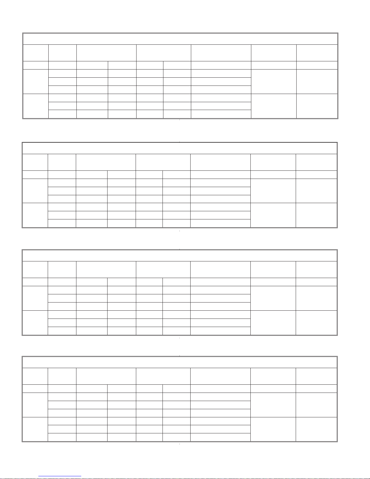
MODEL GH 100 SPECIFICATIONS
FUEL BLOWER
NATURAL
GAS
PROPANE
(LP GAS)
SPEED
MAX 119,000 119,000 100 100 -0.05
MIN (B,P) 60,000 60,000 50 50 -0.05
MIN (MC) 40,000 60,000 25 50 -0.05
MAX 119,000 119,000 100 100 -0.05
MIN (B,P) 60,000 60,000 50 50 -0.05
MIN (MC) 48,000 60,000 30 50 -0.05
* For high altitude units (2000-4500 ft) the input and steam capacities are de-rated by 10%. STD: Standard Gas Unit DV: Direct Vent Unit
INPUT (BTUH)* STEAM CAPACITY
STD DV STD DV
(LBS/HR)
MANIFOLD PRESS. IN
W.C.
SHIPPING WEIGHT
(LBS)
300 500
300 500
OPERATING
WEIGHT (LBS)
MODEL GH 200 SPECIFICATIONS
FUEL BLOWER
NATURAL
GAS
PROPANE
(LP GAS)
SPEED
MAX 238,000 238,000 200 200 -0.05
MIN (B,P) 120,000 120,000 100 100 -0.05
MIN (MC) 40,000 60,000 25 50 -0.05
MAX 238,000 238,000 200 200 -0.05
MIN (B,P) 120,000 120,000 100 100 -0.05
MIN (MC) 48,000 60,000 30 50 -0.05
INPUT (BTUH)* STEAM CAPACITY
STD DV STD DV
(LBS/HR)
MANIFOLD PRESS. IN
W.C.
SHIPPING WEIGHT
(LBS)
350 660
350 660
OPERATING
WEIGHT (LBS)
* For high altitude units (2000-4500 ft) the input and steam capacities are de-rated by 10%. STD: Standard Gas Unit DV: Direct Vent Unit
MODEL GH 300 SPECIFICATIONS
FUEL BLOWER
NATURAL
GAS
PROPANE
(LP GAS)
SPEED
MAX 357,000 357,000 300 300 -0.05
MIN (B,P) 180,000 180,000 150 150 -0.05
MIN (MC) 40,000 60,000 25 50 -0.05
MAX 357,000 357,000 300 300 -0.05
MIN (B,P) 180,000 180,000 150 150 -0.05
MIN (MC) 48,000 60,000 30 50 -0.05
* For high altitude units (2000-4500 ft) the input and steam capacities are de-rated by 10%. STD: Standard Gas Unit DV: Direct Vent Unit
INPUT (BTUH)* STEAM CAPACITY
STD DV STD DV
(LBS/HR)
MANIFOLD PRESS. IN
W.C.
SHIPPING WEIGHT
(LBS)
800 1200
800 1200
OPERATING
WEIGHT (LBS)
MODEL GH 400 SPECIFICATIONS
FUEL BLOWER
NATURAL
GAS
PROPANE
(LP GAS)
SPEED
MAX 476,000 476,000 400 400 -0.05
MIN (B,P) 240,000 240,000 200 200 -0.05
MIN (MC) 40,000 60,000 25 50 -0.05
MAX 476,000 476,000 400 400 -0.05
MIN (B,P) 240,000 240,000 200 200 -0.05
MIN (MC) 48,000 60,000 30 50 -0.05
INPUT (BTUH)* STEAM CAPACITY
STD DV STD DV
(LBS/HR)
MANIFOLD PRESS. IN
W.C.
SHIPPING WEIGHT
(LBS)
800 1200
800 1200
OPERATING
WEIGHT (LBS)
* For high altitude units (2000-4500 ft) the input and steam capacities are de-rated by 10%. STD: Standard Gas Unit DV: Direct Vent Unit
-2-
Codes, or applicable provisions of the local
O
building codes.
8. For recommended clearances for servicing
refer to Figure #2.
4. The required free area of supply air opening
is:
11 in. sq. (7,000 mm
20 in. sq. (13,000 mm
30 in. Sq. (19,500 mm
40 in. Sq. (26,000 mm
2
), for GH 100
2
), for GH 200
2
), for GH 300
2
), for GH 400
NOTE FOR DIRECT VENT OPTION:
The combustion supply air opening is not
required to the room where the appliance is
installed since the combustion air
requirements will be provided through the inlet
air duct (see installation section). To keep
electronic components cooled, it is required to
keep the environment around the unit at room
temperature.
NOTE FOR OUTDOOR ENCLOSURE:
Required free area of supply air is provided
through the bottom of the unit. Front louvers
ensure good air circulation in the summer.
These louvers should be blocked for winter
operation.
5. Cabinet back and bottom contain air openings
to provide combustion air to the forced draft
blower. Either the back or bottom set of
openings must have at least 2" (50 mm)
clearance to allow for adequate combustion
air. For example, if the humidifier is floor
mounted, 2" clearance must be maintained to
the unit's back surface.
6. Excessive exposure to contaminated
combustion air will result in safety and
performance related problems. Known
contaminates include halogens, ammonia, and
chlorides, excessive dust, lime or dirt.
Excessive exposure of electronics to the
contaminants will also result in performance
related problems. Contact NORTEC Technical
Services if you have any questions. If
contaminants exist, it is recommended to use
the outdoor enclosure option to isolate the
unit.
7. All surfaces are zero clearance to combustible
construction.
9. During installation cover the humidifier to
prevent any dust or other contaminants from
entering the cabinet when activities such as
drilling are taking place.
NOTE: Some insulating materials may be
combustible. Prior to installing this appliance
examine the area for insulating material. If
this appliance is installed in an insulated
space, it must be kept free and clear of
insulating materials. If insulation is added
after the appliance is installed, it will be
necessary to examine the area again.
LOCATING AND MOUNTING
GH Series humidifiers are designed to mount on a
suitable wall (GH 100 only), GH Stand, or floor. The
clearance dimensions shown in this manual are for
reference only and are the minimum required for
maintenance of the humidifier. Local and National
Codes should be consulted prior to final location and
installation of the humidifier. NORTEC cannot accept
responsibility for installation code violations.
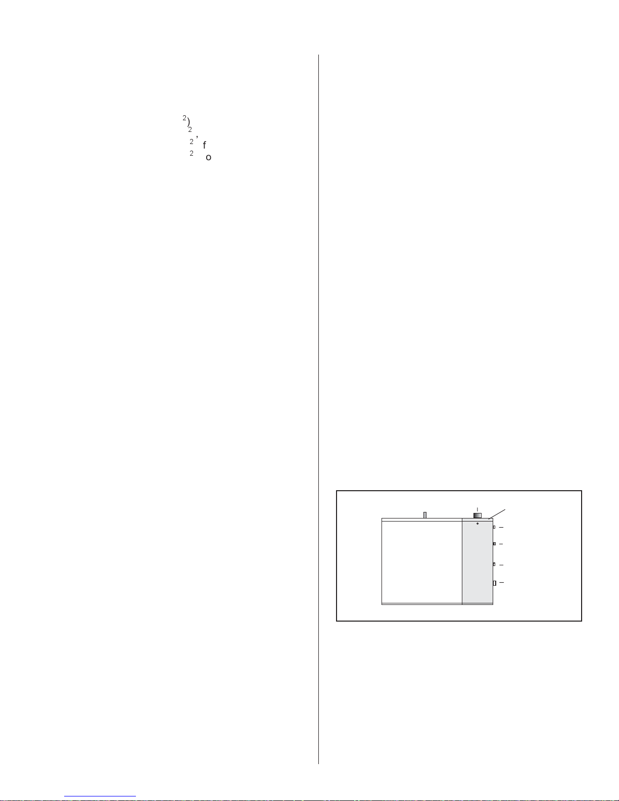
1. Figure #1 shows the locations of all required
connections to the Gas Humidifier. Careful
consideration should be given to all of these
connections when choosing a location for the
humidifier.
Figure #1
EXHAUST VENT C
OUT FROM THE TOP
Steam
Outlet(s)
2. For front and side clearance requirements (for
access during installation, maintenance and
troubleshooting), see Figure #2.
MES
Power And
Control Wiring
Fill Water Input
Line
DWC Water Input
Line*
Gas Input
Line
Drain
*DWC = Drain Water Cooler
NOTES:
The leveling legs must be left in place when
floor mounted on combustible material.
The humidifier shall not be installed directly on
carpeting, tile or other combustible
material other than wood flooring.
3. Location of the steam distributor should be
minimum of 36” above the humidifier.
4. DO NOT locate humidifier any further than
absolutely necessary from steam distributor
location. Net output will be reduced as a result
of heat loss through steam hose (see
Engineering Manual, Form # -163D). Also,
-3-
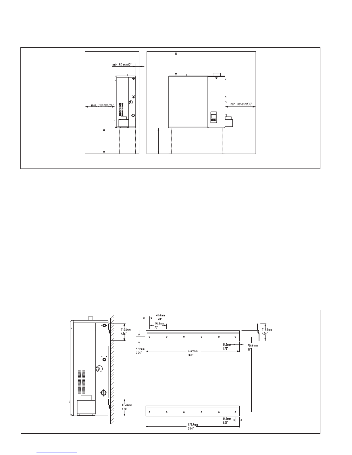
p
Figure #2
**
Front
800 mm/31.5”
(min. 50 mm/2”) **
DV: Optional Direct Vent option
ace required for combustion air below or at the back of the unit.
**: S
increased static pressure (over 4.5" W.C.) will
result in hot water leaking down the drain.
Consult factory if this situation occurs.
5. Where possible, mount humidifier at a height
convenient for servicing.
6. Wall mounting brackets (provided with GH
100) should be securely attached open edge
upwards, horizontal, using field-supplied
fasteners (minimum of four 3/8" diameter
fasteners in each bracket). Attach to a
vertical, solid surface. Put a security bolt
through the hole provided in the back of the
cabinet so that the unit cannot be bumped off
the wall bracket. See Figure #3.
0mm
80
(min. 50 mm/2”)**
TOP
min. 915 mm/36”
RIGHT
DV
BOTTOM
7. Make sure humidifier is mounted level. If floor
mounted adjust using leveling legs.
All GH models are equipped with adjustable
leveling legs which have a maximum travel of
1.5”.
- These legs may be used to allow mounting of
an optional stand.
- These legs may be removed and replaced by
longer legs. Factory approval is needed.
- Removal or adjustment of legs requires a
1 1/8” wrench.
Figure #3
-4-
8. Optional stands are available for all GH Series
humidifiers. Refer to Shop Drawing Package,
Form # 273 for details and part numbers.
9. Clearances around the unit should also be
maintained for good access to the gas
humidifier. 3 feet clearance is needed on the
right side of the cabinet for GH100/200, 4 feet
is needed on the right side of the cabinet for
the GH300/400. The front requires 3 feet
clearance for all capacities.
GAS PIPING
Installation of piping must be in accordance with
local codes, and ANSI Z233.1, “National Fuel Gas
Code,” in the United States or CAN/CGA-B149
Installation Codes in Canada.
The following table indicates the maximum and
minimum allowable gas pressures for the Gas
Humidifier.
10. DO NOT mount humidifier on hot surfaces.
11. DO NOT mount humidifiers in an area where
freezing may occur.
12. If humidifiers are mounted on roof, a properly
ventilated, temperature controlled, (above
freezing), weatherproof enclosure must be
used. Consult your local representative for
more information on Nortec’s enclosure.
13. DO NOT mount humidifiers on vibrating
surface. Consult factory.
14. In earthquake prone areas do not wall mount.
Use the existing wall mount brackets to fasten
unit to the wall with it sitting on the floor.
Maintain spacing for air openings. (See
“Installation” item 8).
NOTE FOR OUTDOOR ENCLOSURE:
1. Optional outdoor enclosure can also be used;
unit is factory mounted inside the enclosure.
INCHES W.C.
GAS MIN. MAX.
Natural 4.5 14.0
Propane 9.0 14.0
The gas inlet pipe size to the appliance is:
½” NPT for GH 100
3/4” NPT for GH 200
1” NPT for GH 300 / 400
Provide an adequate size gas supply line.
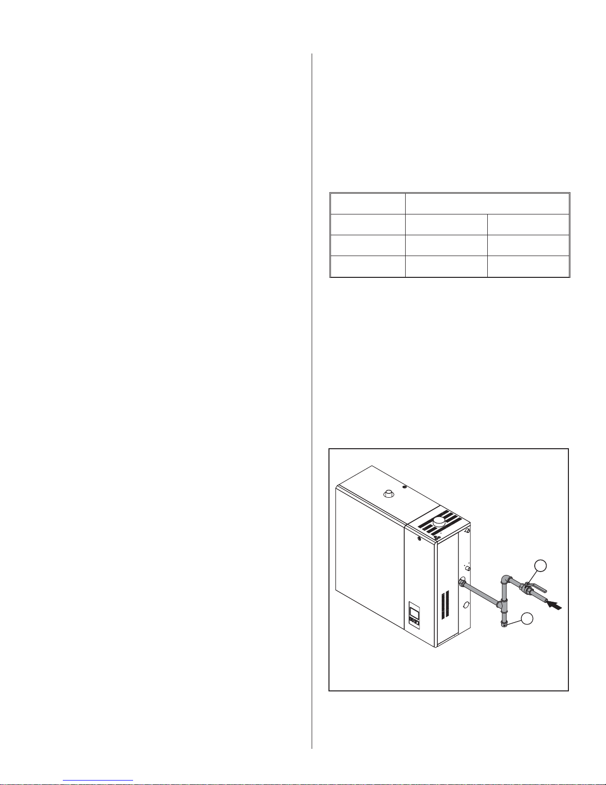
When black iron gas pipe is used, a sediment trap
must be located ahead of the humidifier gas controls.
In all installations, a manual shut off valve, located
outside the cabinet, must be installed. See Figure #4.
Figure #4
2. The enclosure should be installed at a secure
distance from any air or exhaust system. (also
see local code).
3. The enclosure should be bolted down or
secured if it is to be exposed to high winds.
4. If lifting the enclosure on the roof using a
forklift, lift under the unit at cross members for
stability. (Strapping belts can also be used.)
5. Clearances around the unit should also be
maintained for good access to the gas
humidifier. 3 feet of clearance is needed on
the right side of the cabinet for GH100/200, 4
feet is needed on the right side of the cabinet
for the GH300/400. The front requires 3 feet
clearance for all capacities.
1
2
#1: Shut-off Gas Valve
#2: Sediment Trap
Leak test all gas connections using a commercial
soap solution made to detect leaks. Bubbles indicate
-5-
gas leakage. Seal all leaks before placing the
humidifier in operation.
installed by a qualified installer prior to commissioning
the unit.
WARNING: Never use an open flame to check for
gas leaks. If a leak does exist, a fire or explosion
could occur, resulting in damage, injury or death.
The appliance must be isolated from the gas
supply piping system by closing its individual manual
shut-off valve during any pressure testing of the gas
supply piping system at test pressures equal to or
greater than 14” w.c. (3.5 kPa).
Dissipate test pressure from the gas supply line
before re-opening the manual shut off valve to the
appliance.
NOTES:
1. Failure to follow this procedure may damage
the gas valve. Over pressured gas valves are
not covered by warranty.
2. DO NOT use Teflon tape on gas line pipe
threads. A flexible sealant suitable for use
with Natural Gas and Propane Gas is
recommended.
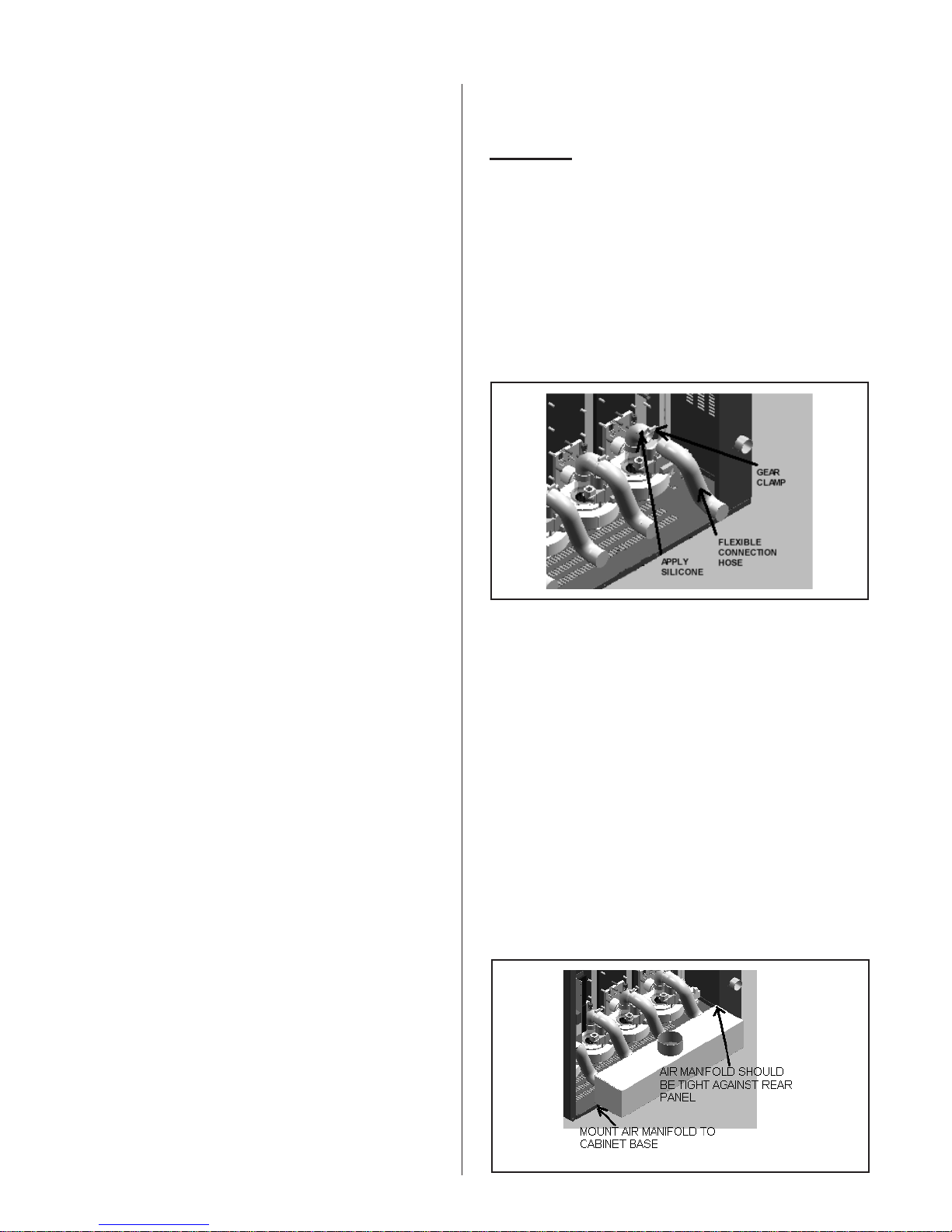
Procedure:
1. Apply a ring of silicone around the outside of
each of the blower adapter connector.
2. Mount a flexible connector hose over the hose
connection on each blower adapter and
secure using a gear clamp provided with the
unit. Care should be taken not to kink or
damage the flexible hose. Refer to Figure #5.
Figure #5
3. Plan gas supply piping so it will not interfere
with removal of gas valves or blower
assemblies and front or side service doors.
The gas valve is provided with pressure taps to
measure gas pressure upstream and downstream,
(manifold pressure). The minimum gas pressure
shown is for the purpose of input adjustment.
A 1/8" NPT plugged tapping, accessible for test
gage connection, must be installed immediately
upstream of the gas supply connection to the
appliance.
NOTE FOR OUTDOOR ENCLOSURE: Gas lines
should be routed through the bottom of the enclosure.
NOTE FOR DIRECT VENT UNITS: The
combustion supply air opening is not required to the
room where the appliance is installed since the
combustion air will be provided through the inlet air
duct (see installation notes below). Ventilation is
required for cooling of the electronic components
AIR MANIFOLD/CONNECTOR HOSE
INSTALLATION FOR DIRECT VENT
3. Carefully bend the flexible hose(s) to give the
“S” shape as shown in the diagram.
4. Mount the air intake manifold to the cabinet
base using the mounting bracket located on
the bottom of the air manifold (refer to Figure
6). DO NOT PUNCTURE OR ADD ANY
HOLES TO THE AIR MANIFOLD.
5. Apply a ring of silicone to the outside of each
hose connection on the air manifold.
6. Mount the corresponding flexible connector
hose over each hose connection on the air
manifold and secure using a gear clamp
provided with the unit.
Figure #6
All direct vent units are shipped with the air
manifold and connector hoses packaged separately.
The connector hoses and air manifold must be
-6-
INTAKE AIR DUCT
TERMINAL LOCATION
All direct vent units require an intake air duct to
provide fresh outside air for combustion.
Each air intake manifold has a single 4-inch
(100mm) diameter inlet to which the supply air duct
must be connected.
Intake material must be UL or ULC listed 4-inch
diameter (I.D.) corrugated 2-Ply aluminum ducting.
The following table lists several suppliers of approved
intake material.
Supplier
Z-Flex Z-Flex Aluminum Chim
Product
-
ney Liner
Flex-L International Inc. Flexi-Liner
MICHIGAN CHIM-FLEX CHIM-FLEX Aluminum
Liner
Chim Cap Corp. Flex-All Aluminum Liner
The following table details the allowable duct
length that can be connected to the direct vent
option. Each 90 degree elbow equals 10ft and each
45 degree elbow equals 5ft. If flexible vent material
is used, all bends should be smooth and have as
large a radius as possible to avoid restricting the
combustion air supply.
Allowable Equivalent Intake Lengths
Maximum Minimum
70 ft (21m) 7ft (2.1 m)
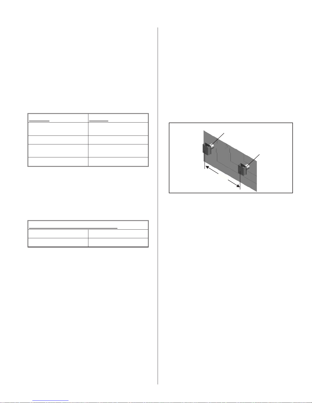
The intake duct must terminate at an outside
location with the supplied vent terminal.
The intake and vent terminals must be installed as
shown in Figure 7.
When locating the intake terminal, a minimum
distance must be maintained from the exhaust vent
terminal to prevent re-circulation of exhaust gases.
Figure 7 shows the proper location of intake and
exhaust terminals on an outside wall.
Figure #7
Exhaust terminal with
opening vertical.
Intake terminal with
opening vertical.
4ft-6ft
Keep a minimum of 6“
away from sidewall.
Periodic cleaning of the screens in the terminal is
required for proper operation.
Location of intake & vent terminal must comply with
all local and national codes.
VENTING
All joints must be positively sealed with a silicone
sealant to ensure that there are no leaks in the duct.
When installed, the intake duct and exhaust vent
should be the same equivalent length.
Condensate may form on the outside of the
intake duct, particularly in colder climates. It is
recommended to insulate the intake duct to prevent
condensation from occurring.
To connect the intake duct to the air manifold:
1. Apply silicone around the outside of the
connector on the top of the air manifold. See
Figure #6.
2. Mount the intake duct over the connector and
secure with an appropriate clamp to ensure a
proper seal has been achieved.
CAUTION: The humidifier shall not be connected to
a chimney flue serving any other appliances. All venting
must be installed in accordance with local and national
codes.
NOTE: These requirements apply to both standard,
direct vent units and units with outdoor enclosure.
NOTE FOR OUTDOOR ENCLOSURE: It is
recommended to vent the gas unit through the sidewalls
of the gas enclosure to eliminate possible leakage
through the enclosure roof.
The vent pipe must be the same diameter as the
vent connector. The supplied vent termination at the
humidifier is a MALE CONNECTION. Standard venting
hook ups require a female to male path. It is highly
recommended that a female to female adapter be
assembled directly onto the humidifier. This will
establish the proper vent sequencing. Consult with
venting contractor/supplier for proper hook up or consult
-7-
manufacturer listing, see page 28. Contact NORTEC
for additional information.
each 45° elbow equals 5'. For lengths over 100’,
consult factory.
Class B vent must not
be used. Class “BH” vent
must be used based on list of approved manufacturers
shown in the installation manual.
GH100 exhaust manifold terminates with 3”O.D.
Stainless Steel Tubing. GH200, 300 and 400 exhaust
manifolds terminate with 4”O.D. Stainless Steel
Tubing.
The maximum flue gas temperature at the
humidifier vent connector will not exceed 480°F. Use
only special gas vents listed for use with Category III
or IV gas burning appliances, such as those listed in
the venting system chart, see page 28. (Listed to UL
Standard 1738 in the USA and ULC-S636 in Canada.)
All venting joints must be positively sealed with
high temperature RTV silicone sealant rated for at
least 480°F.
Operating Venting Temperature
Normal Maximum
All GH 360-380°F
(182-193°C)
450°F
(232°C)
When venting a category IV appliance it is
necessary to provide for condensate removal in the
venting system. This provision may be met by using
the special drain tee as listed in the venting system
chart.
When a drain tee is used it is necessary to install a
trap in the drain to ensure that flue gases do not vent
into the drain. Install the trap with a 12” minimum
height of standing water column.
Install the trap a minimum of 12” below flue vent
with a depth minimum of 3”.
Direct Vent Unit
A maximum exhaust vent length of only 70
equivalent feet (21m) is permitted with the direct vent
option, where each 90º elbow equals 10ft and each
45º elbow equals 5ft. This maximum cannot be
exceeded.
All horizontal runs of the vent pipe shall have a
minimum rise of 1/4” per foot (21 mm/m) and shall be
supported at maximum intervals of 5' (1.5 m) and at
each point where an elbow is used.
The vent terminal must be installed within the
same atmospheric pressure zone as the combustion
air inlet of the humidifier.
Periodic cleaning of the screens in the vent
terminal is required for proper operation of the
humidifier.
NOTE OUTDOOR ENCLOSURE: Flue gases
must be vented out of the enclosure.
ADDITIONAL REQUIREMENTS WHEN VENTING
THROUGH A SIDEWALL
For sidewall venting, locate the humidifier as close
as possible to the wall being used.
Locate the vent terminal at least three feet above
any forced air inlet located within ten feet; or at least
four feet below, four feet horizontally from, or one foot
above any door, window, or gravity air inlet into any
building.
A minimum horizontal clearance of four feet from
electric meters, gas meters, regulator and relief
equipment is required.
Prior to activating the appliance, ensure that the
trap is filled with water and that the drain terminates in
accordance with local plumbing codes.
For any vent lengths over 20 feet long, use
insulated vent. Also provide condensate removal in
the venting system.
WARNING: Provide a screen or barrier to prevent
personal injury in areas where inadvertent personnel
contact with vent pipe can occur.
Standard Unit
The maximum recommended vent length is 100
equivalent feet where each 90° elbow equals 10' and
Locate the vent terminal at least seven feet above
grade when it is adjacent to public walkways.
Locate the bottom of the vent terminal at least
twelve inches above grade or ground, or normally
expected snow accumulation level. The snow level
may be higher on walls exposed to prevailing winds.
Avoid areas where local experience indicates that
condensate drip may cause problems such as above
planters, patios, or over public walkways, or over an
area where condensate or vapor could create a
nuisance or hazard, or could be detrimental to the
operation of regulators, relief valves, or other
equipment.
-8-
Refer to the vent manufacturer's installation
O
instructions.
Figure #8
ELECTRICAL
PRIMARY WIRING
1. Humidifiers require field wiring to primary
voltage terminal blocks. Power requirement is
120 Vac, 15A fused circuit, single phase.
Wiring is fed through a 7/8" hole on upper right
hand side of control compartment. See figure
#1.
2. When installed, the appliance must be
electrically grounded in accordance with local
codes or, in the absence of local codes, with
the National Electrical Code, ANSI/NFPA 70,
and/or the CSA C22.1 Electrical Code, if an
external electrical source is utilized.
3. Connect ground wire to cabinet ground clamp.
4. External wiring sizes must be in accordance
with NEC and/or CEC and existing local
electrical codes and by-laws.
NOTE FOR OUTDOOR ENCLOSURE:
- Primary power should be routed through the grille at
the bottom of the unit.
- Ifbackup heater is used, separate240 Vsupply must
be provided with disconnect brought to the Enclosure
forthe heater.(Heateruses 20A –consultlocal codes
for wiringsize) Seeinstallation drawingprovided with
the heater for instructions on page 32. Note: Heater
may be plugged into 3-pronged, 30 ampere, 240 V
outlet.
-
If units operates during the summer, wire exhaust fan
provided with the enclosure(120V wires supplied with
enclosure), from independent supply.
LOW VOLTAGE CONTROL WIRING
n/Off Signal Loop
(B Models)
External
Internal
A
B
C
12
24 VAC
Available
P/MC MODELS
34
MC MODELS
5
6
8
7
9
Controls are available from NORTEC as
accessories and can be ordered with the humidifier.
Controls by others may also be used as long as they
meet the criteria noted below. The following is a
summary of the common types of controls that may be
used with NORTEC Gas Humidifiers.
A – Wall or Duct Mounted Control On/Off
Humidistat: Wired to make on drop in humidity, break
on rise to setpoint. Set to desired RH. Can be a
make/break set of contacts from a Building Automation
System.
B – Duct Mounted Safety High Limit On/Off
Humidistat: Wired to make on drop in humidity, break
on rise to safety setpoint. Set to approximately 85%
RH as a safety to prevent saturation and wetting in the
duct. Highly recommended for ducted applications.
C – Duct Mounted Safety Air Proving On/Off
Switch: Wired to make when sensing air flow, break
when no air flow. Used as a safety to prevent
saturation when there is no air flow. Highly
recommended for ducted applications.
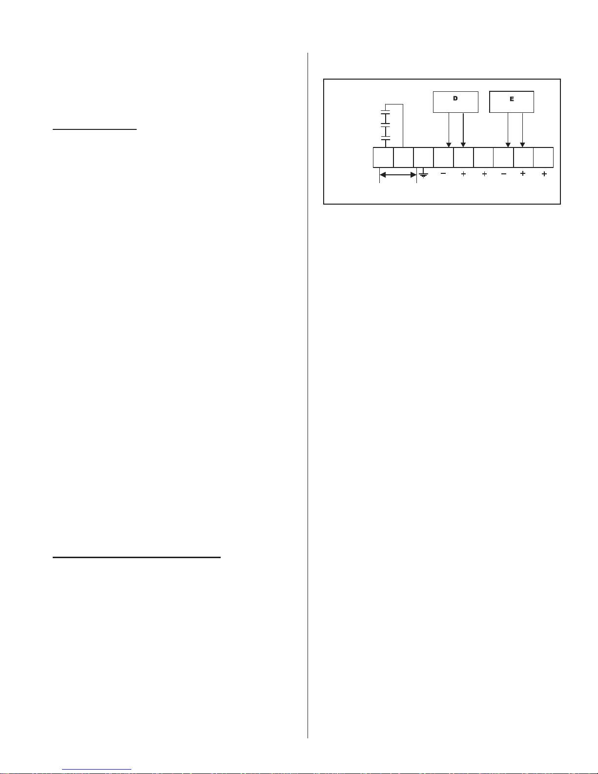
D&E – Wall or Duct Mounted Modulating
Humidistat: Provides a modulating signal to the unit
that represents the output (up to 100%) required from
the humidifier. Refer to the sections below that detail
the signal ranges that can be used with each model.
All GH models require at least one type of input
control signal for unit operation. Refer to the sections
below that detail the types of controls that can be used
with each model.
Low voltage control terminal strips are provided in
the electrical compartment. Internal sides are factory
wired. External sides are to be field wired. Refer to
the specific control-wiring diagram supplied with each
unit.
Field wiring from humidistat to humidifier and
between devices should be 18 AWG or heavier and
kept as short as possible.
NOTE FOR OUTDOOR ENCLOSURE: Control
wiring should be routed through the grill at the bottom
of the unit.
GHB MODELS
GHB models will accept on/off controls only (see
A, B & C on figure #8). In general, A is essential
whereas B and C are optional. On/Off controls are to
be wired in series (only one path for current) across
terminals 1 and 2 on the low voltage control terminal
strip. All on/off controls used must be of the type that
the contacts are closed when operation is required and
open to shut off the unit. A jumper wire may be placed
-9-

across these terminals to replace on/off controls and
provide for constant operation.
Caution: Terminal 1 is the “hot” wire from the
24Vac control transformer; it will trip the 3A breaker on
the transformer if any control field wiring touches
ground metal.
GHP MODELS
GHP models accept a single 0-10 VDC or 0-20
mA control signal (see D on Figure #8) across
terminals 4 and 5 on the low voltage terminal strip to
generate a modulating output from the humidifier.
Terminals 1 and 3 are 24 Vac and ground respectively
and may be used to power a remote mounted
modulating humidistat.
An on/off security loop exists across terminals 1
and 2 and should be wired as described for GHB
models.
3. Mount duct high limit humidistat downstream
of steam distributors far enough that, under
normal humidity and air flow conditions, steam
will have been fully absorbed (typically at least
10 feet). It must be located to sense high
humidity only when uniform and representative
air is over-humidified or approaching
saturation.
4. Mount duct air-proving switch so that it is able
to sense air flow or lack of it. Wire it to make
when air flow is sensed and break when air
flow fails.
5. Check operation of all on/off controls before
starting humidifier.
6. Calibration of controls (on/off or modulation) in
the field may be necessary due to shipping
and handling. Verify humidistat accuracy
before commissioning system.
GHMC MODELS
GHMC models may be configured for either single
or dual channel modulation. Control signals can be
0-10 VDC or 0-20 mA (0-5 VDC, 1-5 VDC, 4-20 mA
and 2-10 VDC are also available). The unit must be
ordered from the factory for the desired signal type
and number of channels. When configured for
2-channel modulation the humidifier will generate
steam only if both channels indicate a demand (see
D&E on figure #8). If both channels are demanding
steam the humidifier will satisfy the lower demand
signal.
An on/off security loop exists across terminals 1
and 2 and should be wired as described for GHB
models.
CONTROL INSTALLATION
1. Mount any wall humidistat (control or high
limit) over standard electrical box at height
similar to typical thermostat. Any wall
humidistat should be in location representative
of overall space being humidified and not in
path of blower pack or air supply grille. Do not
mount on an outside wall where temperature
fluctuations can affect control response.
2. Mount duct humidistat in location
representative of overall air humidity, usually
in return duct. Do not mount it directly in front
of steam distributor or in turbulent or mixing
zone. Mount humidistat where air's humidity
and temperature are uniform and
representative of spaces being humidified.
OUTDOOR ENCLOSURE HEATER
SETTING
Position #1 on the heater will maintain the air
around the heater at around 60ºF. Each increment
changes the set-point by an additional 16ºF. The off
position can be obtained by turning the knob counter
clockwise. The set-point position is at 3 O’clock.
BLOWER PACKS
1. Blower packs are an optional accessory used
to directly distribute steam to localized areas
(such as computer rooms) or in structures that
do not have a built-in air distribution system.
2. Blower packs are remote mounted only. See
Blower Pack Manual XX-277 for requirements
and installation instructions.
STEAM DISTRIBUTORS FOR DUCTED
APPLICATIONS
1. Any humidifier's steam line may be divided
into multiple branches to feed more than one
distributor. Steam supply line “tees” are
common copper fittings that are available for
this purpose. Do not install zone valves on any
of the steam supply lines.
2. Steam distributor locations are typically as
follows: supply air duct, return air duct, air
handling unit. Proper location should
consider: air temperature, relative humidity
before the distributor, air velocity, dimensions
-10-
 Loading...