

Nortec GH, GH100, GH200, GH400 Maintenance Manual
GH Series
lIortec
WHEN
FOR YOUR SAFETY:
Do not store or use gasoline or other flammable vapors and liquids
or any other appliance.
YOU
NEED
HUMIDITY
Gas Fired Humidifier
Inst lIation, User &
Maintenance Guide
in
the vicinity of this
WHAT
Do not try to light any appliance.
Do not touch any electrical switch; do not use any telephone
Immediately call your gas supplier from a neighbor's telephone.
Follow the gas supplier's instructions. If you can not reach your gas supplier, call the fire
department.
WARNING:
Improper installation,
property damage. Refer to this manual. For assistance or additional information consult
a qualified installer, service agency, or the gas supplier.
WARNING:
causin
TO DO IF YOU
adjustment, alteration, service or maintenance can cause injury or
SMELL
GAS:
in
your building.
IMPORTANT: Read and save this guide for future
reference. This guide to
Form 98-272
be
left with equipment owner.
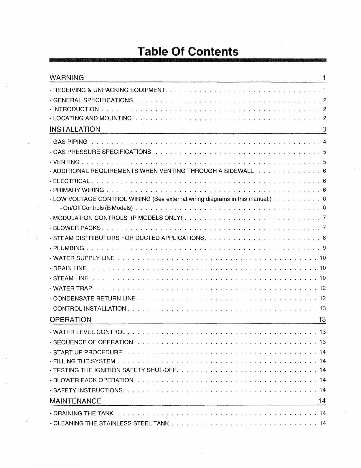
Table
Of
Contents
WARNING
- RECEIVING & UNPACKING EQUIPMENT. . . . . . . . . . . . . . . . . . . . .
- GENERAL SPECIFICATIONS
- INTRODUCTiON . . . . . . . . . . . . . . . . . . . . . . . . . . . . . . . . . . .
- LOCATING AND MOUNTING
.............................
...............................
..
..
.
.
.
· . . . 1
·
...
·
...
. . 2
3
- GAS PIPING . . . . . . . . . . . . . . . . . . . . . . . . . . . . . . . . . . . . . . .
- GAS PRESSURE SPECIFICATIONS . . . . . . . . . . . . . . . . . . . . . . . . . .
~
VENTING.
ADDITIONAL REQUIREMENTS WHEN VENTING THROUGH A SIDEWALL . .
-
- ELECTR
PRIMARY
-
- LOW VOLTAGE CONTROL WIRING (See external wiring diagrams
-On/Off Controls
MODULATION CONTROLS
-
- BLOWER PACKS. . . . . . . . . . . . . . . . . . . . . . . . . . . . . . . . . . . . . . . . . . . 7
STEAM DISTRIBUTORS FOR DUCTED APPLICATIONS. . . . . . . . . . . . . . . .
PLUMBING.
-
- WATER
- DRAIN
. . . . . . . . . . . . . . . . . . . . . . . . . . . . . . . . . . . . . . . . .
ICAL.
SUPPLY
LINE.
. . . . . . . . . . . . . . . . . . . . . . . . . . . . . . . . . . . . . .
WIRING.
. . . . . . . . . . . . . . . . . . . . . . . . . . . . . . . . . . . . . . . . . .
. . . . . . . . . . . . . . . . . . . . .
. . . . . . . . . . . . . . . . . . . . . . . . . . . . . . . . . . . .
in
this manuaL). .
(B
Models) . . . . . . . . . . . . . . . . . . . . . . . . . . . . . .
(P
MODELS ONLY) . . . . . . . . . . . . . . . . . . . .
LINE.
. . . . . . . . . . . . . . . . . . . . . . . . . . . . . . . . .
..
. . . . . . . . . . . . . . . . . . . . . . . . 10
..
..
..
..
..
..
..
..
.
....
.
....
...
...
. . . . 6
...
.
...
.
...
.
...
.
...
...
.
...
8
9
10
1
2
2
4
5
5
6
6
6
6
7
- STEAM LINE . . . . . . . . . . . . . . . . . . . . . . . . . . . . . . . . . . . . . . . . . 10
...
12
12
13
13
13
13
14
14
14
14
14
14
14
WATER TRAP
-
-
CONDENSATE RETURN LINE
- CONTROL INSTALLATION
..................................
.........................
...........................
.
.
.
OPERATION
- WATER LEVEL CONTROL
SEQUENCE OF OPERATION . . . . . . . . . . . . . . . . . . . . . . . .
-
- START
-
FILLING THE SYSTEM . . . . . . . . . . . . . . . . . . . . . . . . . . . . . . . .
TESTING THE IGNITION SAFETY SHUT-OFF
BLOWER PACK OPERATION
-
- SAFETY INSTRUCTIONS
UP
PROCEDURE. . . . . . . . . . . . . . . . . . . . . . . . . . . . . . . . . 14
.........
.............................
............
.
....
.............................
.
MAINTENANCE
- DRAINING THE TANK . . . . . . . . . . . . . . . . . . . . . . . . . . . . .
CLEANING THE STAINLESS STEEL TANK
-
....................
..
..
.
.
.
....
.
.. ' ..
.

- COMBUSTION
- BURNER
- BURNER REMOVAUINSPECTION
- ADJUSTMENTS/REPLACEMENTS OF COMPONENTS.
-Gas Valve Replacement
-Hot Surface Igniter Replacement.
Ignition Module Replacement
-
-Transformer Replacement. . . .
-Air Switch Replacement . . . . .
-Combustion Air Blower Replacement .
-Tank Replacement.
- BLOWDOWN CALIBRATION
BLOWER.
..............
. . . . . .
.....
.........
......
.
..
.
.
15
15
15
15
15
15
16
16
16
16
16
16
- MANUAL STEAM OUTPUT ADJUSTMENT
- SERVICING THE UNIT
- FAULT
SERVICE
TROUBLESHOOTING GUIDE 18
-
- GH REPLACEMENT PARTS . . . . . . . . . . . . . . . . . . . . . . . . . . . . . . . . . . . . 19-22
- GH B/P EXTERNAL
- GHB 100 INTERNAL WIRING DIAGRAM.
- GHP 100 INTERNAL WIRING DIAGRAM.
- GHB 200 INTERNAL WIRING DIAGRAM.
- GHP 200 INTERNAL WIRING DIAGRAM.
- GHB
- GHP
CONDITIONS.
CHECKS.
400 INTERNAL WIRING DIAGRAM.
400 INTERNAL WIRING DIAGRAM.
..
. . . . 17
. . . . . 17
WIRING DIAGRAMS . 23
(B
MODELS)
..
16
17
24
·
· 25
· 26
27
·
28
·
29
·
WARNING
..
Improper installation, adjustment, alteration,
service, maintenance, or use can cause carbon
monoxide poisoning, an explosion, fire,
shock, or other conditions which may cause
personal injury or property damage. Consult a
qualified installer, service agency, local gas
supplier, or your distributor or branch for
information or assistance. The qualified
or agency must use only factory authorized and
listed kits
product. A failure to
cause
or
accessories when modifying this
follow this warning can
electrical shock, fire, personal injury, or
death.
..
Should overheating occur, or the gas fail to shut
off, shut off the manual gas valve to the appliance
before shutting off the electrical
..
Do not use this appliance if any part has been
under water.
Immediately call a qualified service
supply.
technician to inspect the appliance and to replace
any part of the control system and any gas
control which has been under water.
electrical
installer
4.
After unpacking, inspect equipment for
damage and
shipper
5.
All
NORTEC products are shipped
if
damage is found, notify the
promptly.
F.O.B. factory basis. Any and all damage,
breakage or
loss claims are to
directly to the shipping company.
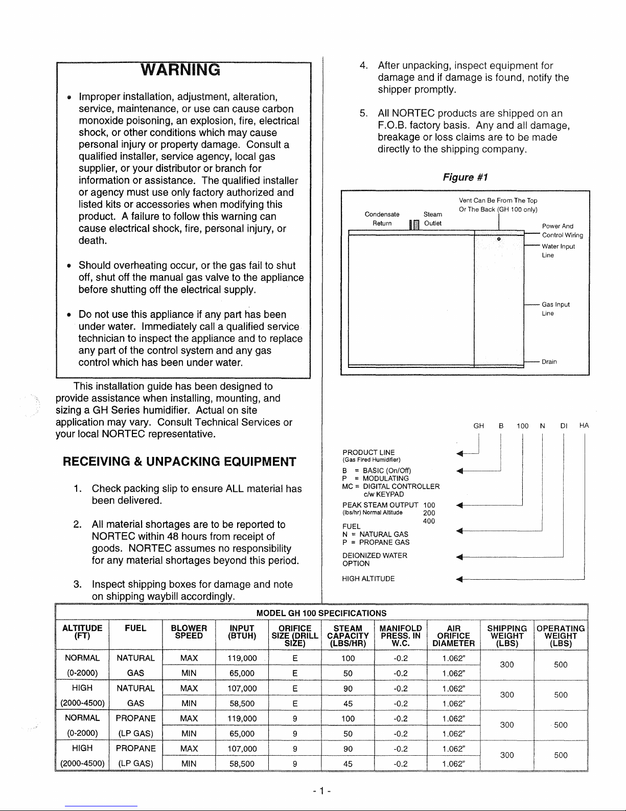
Condensate Steam
Return
II
Outlet
Figure
#1
Vent Can Be From The
Or The Back (GH 100 only)
1 Power And
1:::::::=========:::±:::====l1---
be
Top
i--
i---
I---
on
an
made
Control Wiring
Water Input
Line
Gas Input
Line
Drain
installation guide has been designed to
This
provide assistance when
sizing a GH
Series humidifier. Actual on site
installing, mounting, and
application may vary. Consult Technical Services or
local NORTEC representative.
your
RECEIVING & UNPACKING EQUIPMENT
1.
Check packing slip to ensure ALL material has
been delivered.
2.
All material shortages are
NORTEC within 48 hours from receipt of
goods.
for any
3.
Inspect shipping boxes for damage and note
on shipping waybill accordingly.
ALTITUDE
(FT)
NORMAL
(0-2000)
HIGH
(2000-4500)
NORMAL
(0-2000)
HIGH
(2000-4500)
NORTEC assumes no responsibility
material shortages beyond this period.
FUEL BLOWER
NATURAL
GAS MIN 65,000
NATURAL MAX
GAS
PROPANE
(LP GAS)
PROPANE
(LP GAS)
SPEED
MAX
MAX
MAX 107,000
to
be
reported to
INPUT ORIFICE
(BTUH)
119,000
107,000
MIN 58,500
119,000
MIN 65,000
MIN
58,500
MODEL
SIZE
SI
PRODUCT LINE
(Gas Fired Humidifier)
B = BASIC (On/Off)
P
= MODULATING
= DIGITAL CONTROLLER
MC
c/w KEYPAD
PEAK STEAM OUTPUT 100
(lbs/hr) Normal Altitude 200
FUEL
N
= NATURAL GAS
P
= PROPANE GAS
DEIONIZED
OPTION
HIGH ALTITUDE
GH
100 SPECIFICATIONS
STEAM
pRILL
E 100 -0.2 1.062"
E 50
E
E 45
9
9 50
9
9 45
CAPACITY
E) (LBS/HR)
90
100
90 -0.2 1.062"
WATER
MANIFOLD
PRESS.
W.C.
400
IN
-0.2
-0.2
-0.2
-0.2
-0.2 1.062"
-0.2 1.062"
AIR
ORIFICE WEIGHT WEIGHT
DIAMETER
1.062"
1.062"
1.062"
1.062"
GH
B 100 N
01
....
~-------------------
SHIPPING
(LBS)
300 500
300 500
300
300 500
OPERATING
(LBS)
500
HA
- 1 -
ALTITUDE
(FT) SPEED
NORMAL
(0-2000)
HIGH
(2000-4500)
NORMAL
(0-2000)
HIGH
(2000-4500)
FUEL
NATURAL
GAS
NATURAL
GAS
PROPANE
(LP GAS)
PROPANE
(LP GAS)
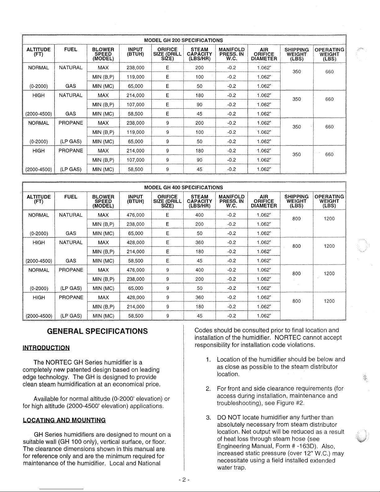
MODEL GH 200 SPECIFICATIONS
BLOWER INPUT ORIFICE STEAM MANIFOLD
(MODEL)
MAX
MIN (S,P)
(MC)
MIN
MAX
MIN (S,P)
(MC)
MIN
MAX
MIN (S,P)
(MC)
MIN
MAX
MIN (S,P)
MIN
(MC)
H)
(BTU
238,000 E 200 -0.2
119,000
65,000 E
214,000 E
107,000
58,500 E 45 -0.2 1.062"
238,000
119,000
65,000 9 50
214,000
107,000
58,500 9 45
SIZE
pRILL
SI
E 100
E 90
9 200
9 100
9
9 90
CAPACITY PRESS. IN
E) (LBS/HR) W.C.
-0.2 1.062"
50
180 -0.2 1.062"
180
-0.2 1.062"
-0.2 1.062"
-0.2 1.062"
-0.2 1.062"
-0.2
-0.2
-0.2 1.062"
-0.2 1.062"
AIR
ORIFICE WEIGHT WEIGHT
DIAMETER
I
1.062"
1.062"
1.062"
SHIPPING
(LBS)
350
350 660
350 660
350 660
OPERATING
(LBS).
660
MODEL
ALTITUDE
(FT) SPEED
NORMAL
(0-2000) GAS MIN
HIGH
(2000-4500)
NORMAL
(0-2000)
HIGH
(2000-4500)
FUEL BLOWER
NATURAL
NATURAL MAX
GAS MIN
PROPANE MAX
(LP GAS)
PROPANE
(LP GAS) MIN (MC)
(MODEL)
MAX
MIN (S,P)
(MC)
MIN (S,P)
(MC)
MIN (S,P)
MIN
(MC)
MAX
MIN (S,P)
INPUT ORIFICE
(BTUH)
476,000
238,000
65,000
428,000
214,000
58,500
476,000
238,000
65,000
428,000
214,000
58,500
GENERAL SPECIFICATIONS
INTRODUCTION
The NORTEC GH Series humidifier
completely new patented design based
is
edge technology. The GH
clean steam humidification at
designed to provide
an
economical price.
Available for normal altitude (0-2000' elevation) or
for high altitude
(2000-4500' elevation) applications.
is
on
a
leading
GH 400 SPECIFICATIONS
STEAM MANIFOLD AIR
SIZE
SI
~DRILL
E
E
E
E
E
E
9
9
9
9
9
9
CAPACITY PRESS.
E)
(LBS/HR) W.C. DIAMETER
400
200
50
360 -0.2 1.062"
180
45
400 -0.2 1.062"
200
50
360 -0.2 1.062"
180
45
Codes should
installation of the humidifier. NORTEC cannot accept
responsibility for installation code violations.
SHIPPING OPERATING
IN
ORIFICE
-0.2 1.062"
-0.2
-0.2
-0.2
-0.2 1.062"
-0.2
-0.2 1.062"
-0.2
-0.2
be
1.
Location of the humidifier should be below and
as
close
1.062"
1.062"
1.062"
1.062"
1.062"
1.062"
consulted prior to final location and
as
possible to the steam distributor
WEIGHT WEIGHT
(LBS) (LBS)
800 1200
800
800 1200
800 1200
location.
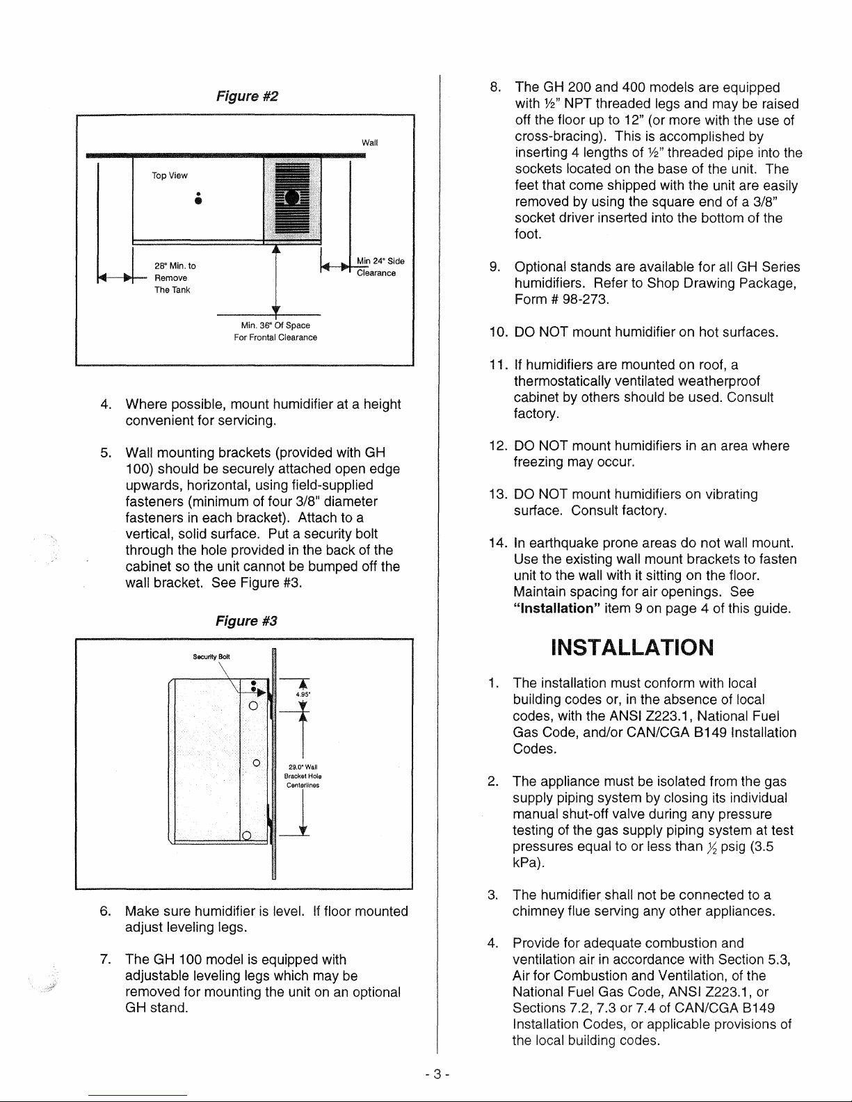
2.
For front and side clearance requirements (for
access during installation, maintenance and
troubleshooting), see Figure #2.
1200
LOCATING AND MOUNTING
GH
Series humidifiers are designed to mount
suitable
The clearance dimensions shown
wall (GH 100 only), vertical surface, or floor.
in
this manual are
for reference only and are the minimum required for
maintenance of the humidifier. Local and National
on
a
2 -
3.
DO
NOT locate humidifier any further than
absolutely necessary from steam distributor
will
be
location. Net output
reduced
of heat loss through steam hose (see
Engineering Manual, Form
increased static pressure (over
nec'essitate using a
field installed extended
# -163D). Also,
12"
water trap.
as
a result
w.e.)
may
Top View
Figure #2
..
•
Wall
8.
The GH 200 and 400 models are equipped
with
%"
NPT threaded legs and may be raised
off the floor up to
cross-bracing). This
inserting 4 lengths of
sockets located
feet that come shipped with the unit are easily
removed by using the square end
socket driver inserted into the bottom of the
foot.
12" (or more with the use
is
accomplished by
%"
threaded pipe into the
on
the base of the unit. The
of
of
a 3/8"
28"
14---8+-
4.
Where possible, mount humidifier at a height
convenient for servicing.
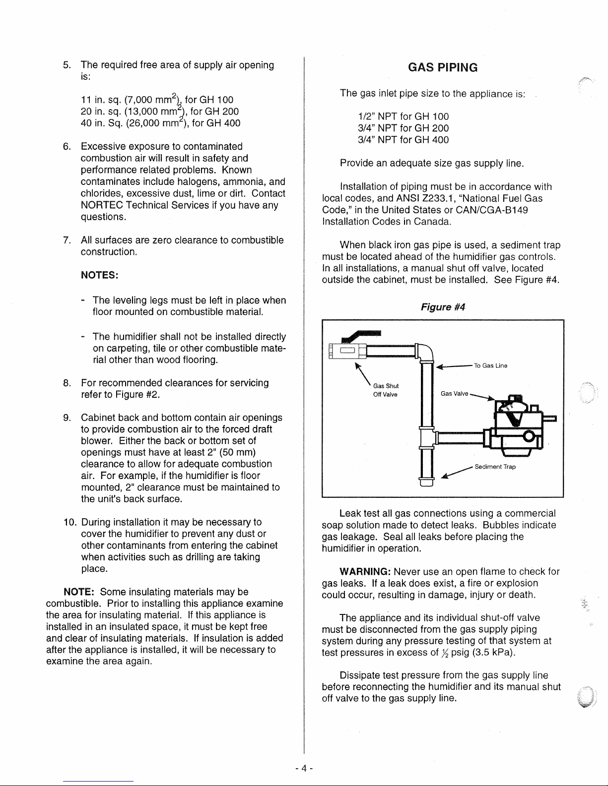
5.
Wall mounting brackets (provided with
100) should be securely attached open edge
upwards, horizontal, using field-supplied
fasteners (minimum of four
fasteners
vertical, solid surface.
through the hole provided
cabinet
wall bracket.
Min. to
Remove
The Tank
in
so
the unit cannot
Security
Min. 36" Of Space
For Frontal Clearance
each bracket). Attach
Put a security bolt
See Figure
Figure #3
Bolt
I4I--IM-C-learance
3/8" diameter
in
the back of the
be
bumped off the
#3.
\
---.
•
\
~
0
0
10
4.95'
1
29.0' Wall
Bracket Hole
Min 24" Side
to
a
GH
9.
Optional stands are available for
humidifiers. Refer
Form # 98-273.
10. DO NOT mount humidifier on hot surfaces.
11.
If humidifiers are mounted on roof, a
thermostatically ventilated weatherproof
cabinet by others should be used. Consult
factory.
12.
DO
NOT mount humidifiers
freezing may occur.
13.
DO
NOT mount humidifiers on vibrating
surface. Consult factory.
14.
In
earthquake prone areas do not wall mount.
Use the existing wall mount brackets to fasten
unit to the wall with it sitting on the floor.
Maintain spacing for air openings.
"Installation"
to
Shop Drawing Package,
item 9 on page 4 of this guide.
all
GH
in
an area where
See
Series
INST ALLATION
1.
The installation must conform with local
building codes
codes, with the
Gas Code, and/or CAN/CGA
Codes.
2.
The appliance must be isolated from the gas
supply piping system by closing
manual shut-off valve during any pressure
testing of the gas supply piping system
pressures equal to or less than
kPa).
or,
in
the absence of local
ANSI Z223.1, National Fuel
8149
Installation
its
individual
at
h psig (3.5
test
6.
Make sure humidifier
adjust leveling legs.
7.
The GH 100 model
adjustable leveling legs which may
removed for mounting the unit
GH stand.
is
level.
is
equipped with
If
floor mounted
be
on
an
optional
- 3 -
3.
The humidifier shall not
chimney
4.
Provide for adequate combustion
ventilation air
Air for Combustion and Ventilation,
National Fuel Gas Code,
Sections
Installation Codes, or applicable provisions of
the local building codes.
flue serving any other appliances.
in
accordance with Section 5.3,
7.2, 7.3 or 7.4
be
connected to a
and
ANSI Z223.1 , or
of
CAN/CGA 8149
of
the
5.
The required free area of supply air opening
is:
GAS PIPING
11
in. sq. (7,000 mm
in. sq. (13,000
20
in. Sq. (26,000 mm
40
6.
Excessive exposure to contaminated
combustion air
2
)
mm?,
),
will result
for GH 100
for GH 200
for GH 400
in
safety and
performance related problems. Known
contaminates include halogens, ammonia, and
chlorides, excessive dust, lime or dirt. Contact
NORTEC Technical Services if you have any
questions.
7.
All surfaces are zero clearance to combustible
construction.
NOTES:
-
The leveling legs must
be
left
in
place when
floor mounted on combustible material.
- The humidifier shall not
be
installed directly
on carpeting, tile or other combustible material other than wood flooring.
The gas inlet pipe size to the appliance
is:
1/2" NPT for GH 100
NPT for
3/4"
3/4"
NPT for
Provide
an
Installation of piping must
local codes, and
Code,"
in
the United States or CAN/CGA-B149
Installation Codes
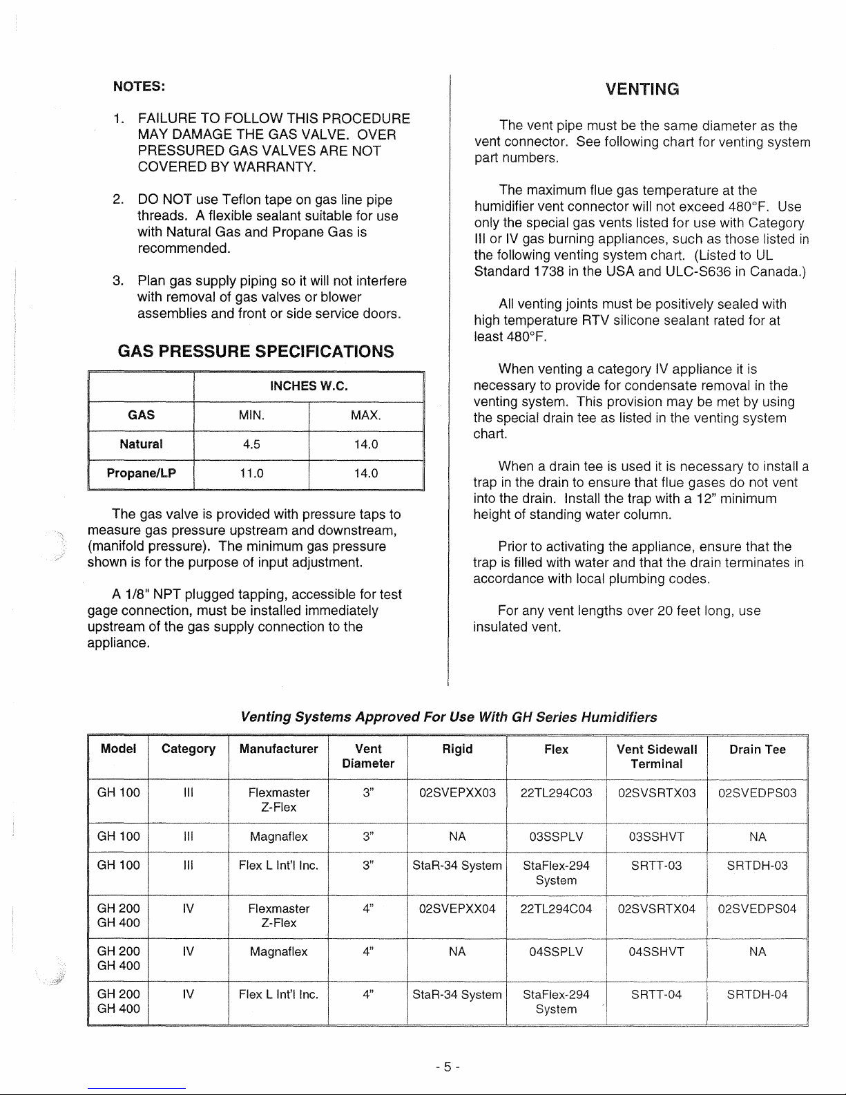
When black iron gas pipe
GH
200
GH
400
adequate size gas supply line.
be
in
accordance with
ANSI Z233.1 , "National Fuel Gas
in
Canada.
is
used, a sediment trap
must be located ahead of the humidifier gas controls.
In
all installations, a manual shut off valve, located
outside the cabinet, must be installed. See Figure #4.
Figure #4
.....
..
_-To
Gas Line
8.
For recommended clearances for servicing
refer to Figure #2.
9.
Cabinet back and bottom contain air openings
to provide combustion air to the forced draft
blower. Either the back or bottom set of
openings must have at least
clearance to
allow for adequate combustion
air. For example, if the humidifier
mounted,
the
2" clearance must
unit's back surface.
10. During installation it may
2" (50 mm)
be
maintained to
be
necessary to
is
floor
cover the humidifier to prevent any dust or
other contaminants from entering the cabinet
when activities such as
drilling are taking
place.
NOTE: Some insulating materials may
be
combustible. Prior to installing this appliance examine
the area for insulating
installed
in
an insulated space, it must be kept free
material.
and clear of insulating materials.
is
after the appliance
installed, it will be necessary to
If
this appliance
If
insulation
is
added
is
examine the area again.
Off
Valve
Leak test all gas connections using a commercial
soap solution made to detect leaks. Bubbles indicate
gas leakage. Seal all leaks before placing the
humidifier
in
operation.
WARNING: Never use an open flame to check for
If
gas leaks.
could occur, resulting
a leak does exist, a fire or explosion
in
damage, injury or death.
The appliance and its individual shut-off valve
be
must
disconnected from the gas supply piping
system during any pressure testing of that system at
test pressures
in
excess of ~ psig (3.5 kPa).
Dissipate test pressure from the gas supply line
before reconnecting the humidifier and its manual shut
off valve to the gas supply line.
4-
NOTES:
1.
FAILURE TO FOLLOW THIS PROCEDURE
MAY DAMAGE THE GAS VALVE. OVER
PRESSURED
COVERED BY
2.
DO NOT use Teflon tape
GAS VALVES ARE NOT
WARRANTY.
on
gas line pipe
threads. A flexible sealant suitable for use
with Natural Gas and
Propane Gas
is
recommended.
3.
Plan gas supply piping so
it
will not interfere
with removal of gas valves or blower
assemblies and front or side service doors.
GAS PRESSURE SPECIFICATIONS
INCHESW.C.
GAS
Natural
Propane/lP
The gas valve
measure gas pressure upstream and downstream,
(manifold pressure). The minimum gas pressure
shown
is
for the purpose of input adjustment.
11
1/8
A
NPT plugged tapping, accessible for test
gage connection, must be
upstream of the gas supply connection to the
appliance.
MIN.
4.5 14.0
11.0 14.0
is
provided with pressure taps
installed immediately
MAX.
to
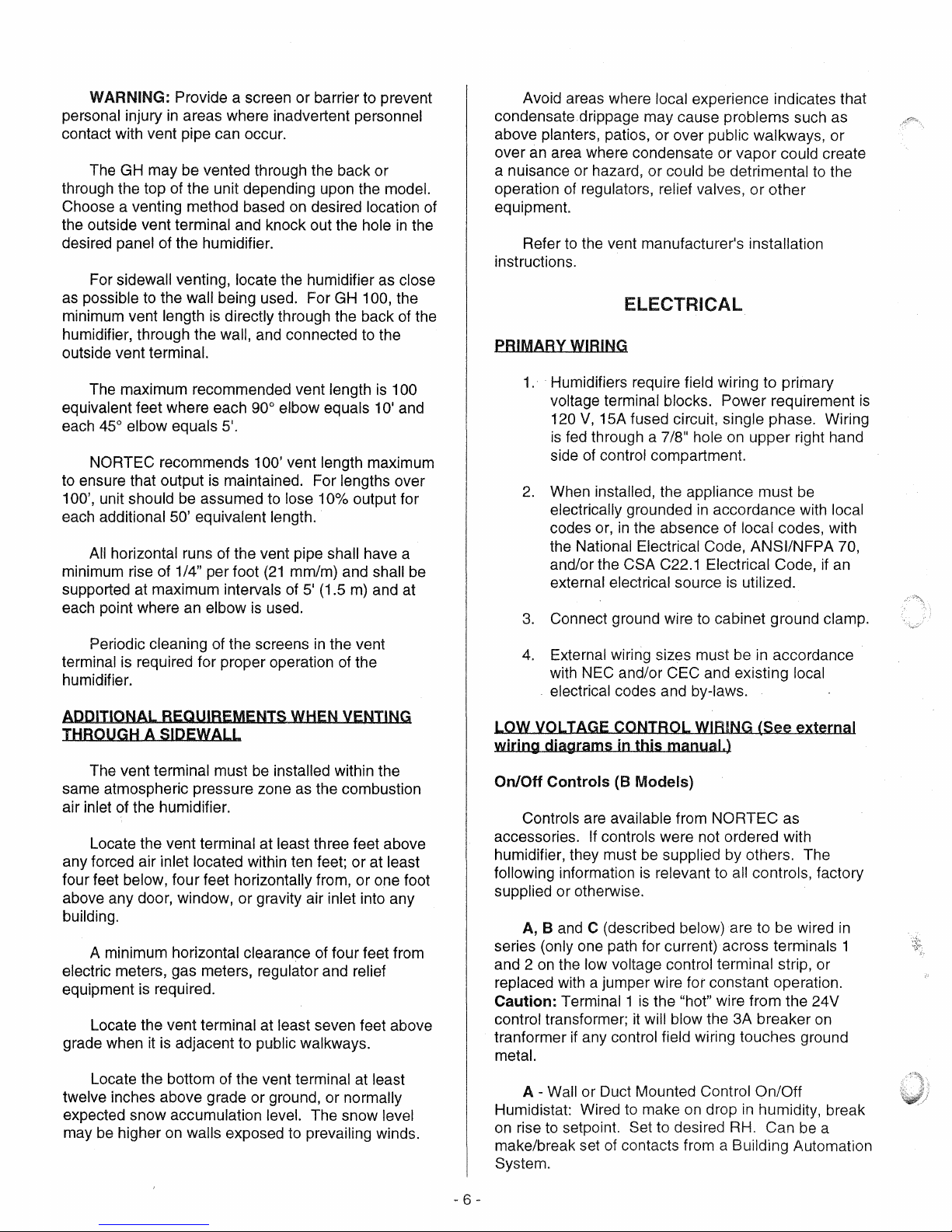
VENTING
The vent pipe must
vent connector. See following chart for venting system
part numbers.
The maximum
humidifier vent connector
only the special gas vents listed for use with Category
III
or
IV
gas burning appliances, such
the following venting system chart. (Listed
Standard 1738
All
venting joints must be positively sealed with
in
high temperature RTV
least 480°F.
When venting a category IV appliance
necessary
to
provide for condensate removal
venting system. This provision may be met by using
the special drain tee as listed
chart.
When a drain tee
in
trap
the drain
into the drain.
of
height
trap
standing water column.
Prior
to
is
filled with water and that the drain terminates
to
Install the trap with a 12" minimum
activating the appliance, ensure that
accordance with local plumbing codes.
For any vent lengths over
insulated vent.
be
the same diameter
as
the
flue gas temperature at the
will not exceed 480°F.
as
the USA and ULC-S636
silicone sealant rated for
in
the venting system
is
used
it
is
necessary to install a
those listed
in
to
UL
Canada.)
at
it
is
in
the
Use
ensure that flue gases do not vent
the
20 feet long, use
in
in
Venting Systems
Model
GH
100
GH
100
GH
100
GH
200
GH400
GH
200
GH
400
GH200
GH400
Category
III
III
III Flex L Int'llnc.
IV
IV
IV Flex L Int'llnc.
Manufacturer
Flexmaster
Z-Flex
Magnaflex
Flexmaster
Z-Flex
Magnaflex
Approved
Vent Rigid
Diameter
3"
3"
3"
4"
4"
4"
For
02SVEPXX03
StaR-34 System
02SVEPXX04
StaR-34 System StaFlex-294 SRTT-04 SRTDH-04
- 5 -
Use With GH Series Humidifiers
Flex
22TL294C03
NA
NA 04SSPLV 04SSHVT NA
03SSPLV 03SSHVT NA
StaFlex-294
System
22TL294C04 02SVSRTX04
System
Vent Sidewall
Terminal
02SVSRTX03 02SVEDPS03
SRTT-03 SRTDH-03
Drain Tee
02SVEDPS04
WARNING: Provide a screen or barrier to prevent
personal injury
contact with vent pipe can occur.
The GH may be vented through the back or
through the top of the unit depending upon the
Choose a venting method based
the outside vent
desired panel of the humidifier.
For
sidewall venting, locate the humidifier as close
as
possible to the wall being used. For
minimum vent length
humidifier, through the
outside vent
The maximum recommended vent length
equivalent feet where each 90° elbow equals 10' and
45° elbow equals 5'.
each
NORTEC
to ensure that output
100', unit should be assumed to lose 10% output for
each additional
All
horizontal runs of the vent pipe shall have a
minimum rise of
supported at maximum intervals of
each point where an elbow
Periodic cleaning of the screens
terminal is required for proper operation of the
humidifier.
ADDITIONAL REQUIREMENTS WHEN VENTING
THROUGH
The vent terminal must
same atmospheric pressure zone as the combustion
air inlet of the humidifier.
Locate the vent terminal at least three feet above
any forced air inlet located within ten feet; or at least
four feet below, four feet horizontally from, or one foot
above any door, window, or gravity air inlet into any
building.
A minimum horizontal clearance of four feet from
electric meters, gas meters, regulator and relief
equipment is required.
Locate the vent terminal at least seven feet above
grade when
Locate the bottom of the vent terminal at least
twelve inches above grade or ground, or
expected snow accumUlation level. The snow level
be
may
higher
in
areas where inadvertent personnel
model.
on
desired location of
terminal and knock out the hole
GH
is
directly through the back of the
wall, and connected to the
terminal.
recommends 100' vent length maximum
is
maintained. For lengths over
50' equivalent length.
1/4" per foot
A SIDEWALL
it
is adjacent to public walkways.
on
walls exposed to prevailing winds.
(21
mm/m) and shall be
5' (1.5
is
used.
in
the vent
be
installed within the
normally
100, the
is
m)
and at
in
100
the
Avoid areas where local experience indicates that
condensatedrippage may cause problems such as
above planters, patios, or over public walkways, or
over an area where condensate or vapor could create
could
be
a nuisance or hazard, or
operation of regulators,
equipment.
Refer
to
the vent manufacturer's installation
instructions.
detrimental
relief valves, or other
to
the
ELECTRICAL
PRIMARY WIRING
1
..
Humidifiers require field wiring to primary
voltage terminal blocks. Power requirement
120
V,
15A fused circuit, single phase. Wiring
is
fed through a 7/8" hole on upper right hand
side of control compartment.
2.
When installed, the appliance must be
in
electrically grounded
codes or,
the National Electrical Code,
and/or the CSA C22.1 Electrical Code, if an
external electrical source
3.
Connect ground wire to cabinet ground clamp.
4.
External wiring sizes must be
with NEC and/or CEC and existing local
. electrical codes and by-laws.
LOW VOLTAGE CONTROL WIRING (See
wiring
On/Off
accessories.
humidifier, they must be supplied by others. The
following information
supplied or otherwise.
series (only one path for current) across terminals 1
and 2
replaced with a jumper wire
Caution:
control transformer;
tranformer
metal.
Humidistat: Wired to make
on
make/break set of contacts from a Building Automation
System.
diagrams
Controls
Controls are available from NORTEC as
8 and C (described below) are to be wired
A,
on
the low voltage control terminal strip, or
Terminal 1
if
A - Wall or Duct Mounted Control
rise
to
setpoint. Set to desired RH. Can
in
the absence of local codes, with
in
this
(8
Models)
If
controls were not ordered with
is
relevant to all controls, factory
is
the "hot" wire from the 24V
it
will blow the 3A breaker
any control field wiring touches ground
accordance with local
ANSI/NFPA 70,
is
utilized.
in
accordance
manual.)
for constant operation.
On/Off
on
drop
in
humidity, break
external
be
is
in
on
a
- 6 -
B - Duct Mounted Safety High Limit On/Off
Humidistat (if used): Wired to make
humidity, break
approximately 85%
saturation and wetting
C - Duct Mounted
Switch
(if used): Wired to make when sensing air flow;
on
rise to safety setpoint. Set to
RH
as
a safety to help prevent
in
the duct.
Safety Air-Proving On/Off
break when no air flow. Used
as
a safety
on
drop
to
in
prevent
saturation when no air flow.
1.
NORTEC offers various versions
C
to
suit each application.
essential, whereas
recommended
2.
Field wiring from humidistat to humidifier and
Band
C are highly
in
ducted applications.
between devices should be 18
heavier and kept as short
3.
Low voltage control terminal strips are
provided
in
the electrical compartment.
as
of
In
general, A
AWG
possible.
A,
or
Band
is
Internal sides are factory wired. External
sides are to be field wired.
4.
Each humidifier
is
supplied with a wiring
diagram.
MODULATION CONTROLS
(P Models Only)
For P Models a single 0-10 VDC or 0-20 mA
is
control signal
low voltage terminal strip
received at terminals 4
to
generate a modulating
output from the humidifier. Terminals 1
Vac output and ground respectively and may
to
power a remote mounted modulating humidistat.
and 5 on
and
3 are 24
be
the
used
NORTEC recommends that the safety loop across
terminal 1 and 2 be utilized for safe operation of the
humidifier (see
control wiring connections of GHMC models see
B & C under on/off controls). For
MC
Manual, Form # 98-274.
BLOWER PACKS
1.
Blower packs are
to
directly distribute steam
(such as computer rooms) or
do not have a built-in air distribution system.
2.
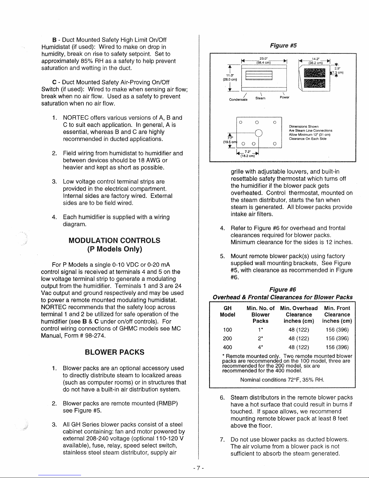
Blower packs are remote mounted (RMBP)
see Figure
3.
All GH Series blower packs consist of a steel
cabinet containing: fan and motor powered by
external 208-240 voltage (optional
available), fuse,
stainless steel steam distributor, supply air
an
optional accessory used
to
localized areas
in
#5.
relay, speed select switch,
structures that
11
0-120 V
Figure #5
230"
(~tJI
Condensate Steam
19
(
:t:'
~72"_~
(~4=)1
/ \
o
o
0 0 0
(18.2cm)
~I
p~er
o
Dimensions Shown
Are
Steam Une Connections
Allow Minimum
Clearance
On
12"
Each
(31
Side
cm)
grille with adjustable louvers, and built-in
resettable safety thermostat which turns off
the humidifier if the blower pack gets
overheated. Control thermostat, mounted
the steam distributor, starts the fan when
is
steam
generated. All blower packs provide
intake air filters.
4.
Refer to Figure
#6
for overhead and frontal
clearances required for blower packs.
is
Minimum clearance for the sides
5.
Mount remote blower pack(s) using factory
supplied
#5, with clearance
wall mounting brackets, See Figure
as
recommended
12
#6.
Figure #6
Overhead &
GH
Model
100
200
400
* Remote mounted only. Two remote mounted blower
packs are recommended
recommended for the
recommended for the
6.
7.
Frontal
Min. No.
Blower Clearance
Nominal
Steam distributors
have a hot surface that
touched.
mounting remote
above the
Do
not use blower packs
Clearances
of
Min. Overhead
Packs inches (cm) inches (cm)
1* 48 (122)
2*
4*
on
200 model, six are
400 model.
conditions 72°F, 35%
in
for
Blower
48 (122) 156 (396)
48 (122) 156 (396)
the 100 model, three are
RH.
the remote blower packs
could result
If
space allows, we recommend
blower pack
at
least 8 feet
floor.
as
ducted blowers.
The air volume from a blower pack
sufficient
to
absorb the steam generated.
Min. Front
Clearance
156 (396)
in
is
inches.
in
Figure
Packs
burns
not
on
if
- 7 -
STEAM DISTRIBUTORS FOR DUCTED
APPLICATIONS
1.
Any humidifier's steam line may
into multiple branches
distributor.
Steam supply line "tees" are
to
feed more than one
common copper fittings that are available for
this purpose.
2.
Steam distributor locations are typically
follows: supply air duct, return air duct, air
handling unit. Proper location should
consider: air temperature, relative humidity
before the distributor, air velocity, dimensions
of the location, amount of steam being
introduced into the duct, downstream
obstructions, and surfaces vulnerable
wetting.
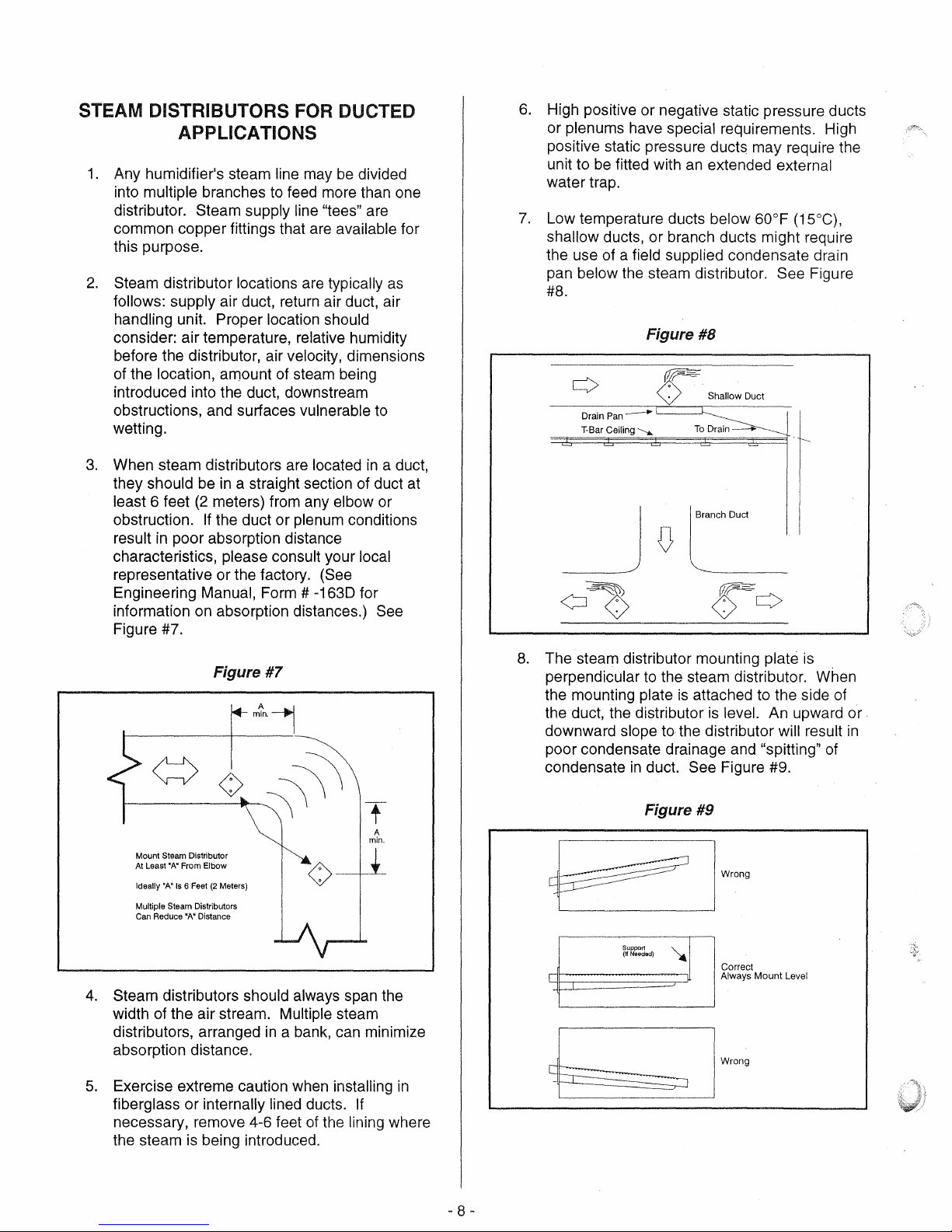
3.
When steam distributors are located
they should be
least 6 feet
obstruction.
in
result
poor absorption distance
in
a straight section of duct at
(2
meters) from any elbow or
If
the duct or plenum conditions
characteristics, please consult your
representative or the factory. (See
Engineering Manual, Form # -1630 for
on
information
absorption distances.) See
Figure #7.
be
divided
as
to
in
a duct,
local
6.
High positive or negative static pressure ducts
or plenums have special requirements. High
positive static pressure duct$ may require the
unit to
fitted with
an
extended external
be
water trap.
7.
Low temperature ducts below 60°F (15°C),
shallow
ducts, or branch ducts might require
the use of a field supplied condensate drain
pan below the steam distributor.
See Figure
#8.
Figure #8
Shallow Duct
Pan
--
Drain
T-Bar
Ceiling
-----...
L-_~
To
Drain---
Branch Duct
Figure #7
Mount Steam Distributor
'A'
At Least
4.
Steam distributors should always span the
From Elbow
'A'
Is 6 Feet
(2
'N
Meters)
Distance
Ideally
Multiple Steam Distributors
Can Reduce
(>-
width of the air stream. Multiple steam
in
distributors, arranged
a bank, can minimize
absorption distance.
5.
Exercise extreme caution when installing
fiberglass or internally lined ducts.
necessary, remove 4-6 feet
is
the steam
being introduced.
of
the lining where
8.
The steam distributor mounting plate
perpendicular
the mounting plate
the duct, the distributor
downward slope
to
the steam distributor. When
is
attached to the side of
is
level. An upward or
to
the distributor will result
poor condensate drainage and "spitting"
condensate
in
duct. See Figure #9.
is
in
of
Figure #9
~
I
WeD,'
Correct
Always Mount Level
Wrong
in
If
- 8 -
 Loading...