

Page 1

GH Series
Gas-fired Humidifier
§
s+j\if
Installation, User.&
Maintenance Guide
FOR YOUR SAFETY:
Do not store or use gasoline or other flammable vapors
or any other appliance.
and
liquids
in
the vicinity
of
this
WHAT TO
Do not try to light any appliance.
Do not touch any electrical switch; do not use any telephone in your building.
Immediately call your gas supplier from a neighbor's telephone.
Follow the gas supplier's instructions.
department.
WARNING:
Improper
property damage. Refer to this
a qualified installer, service agency, or the gas supplier.
WARNING:
If
the information in this manual is not followed exactly, a fire or explosion may result
causing property damage, personal injury or loss
IMPORTANT: Read
DO
IF
YOU SMELL GAS:
If you can not reach your gas supplier, call the fire
installation, adjustment, alteration, service or maintenance can cause injury or
manual. For assistance or additional information consuU
of
life.
and
save this guide for future
reference. This guide to be
Form #00-272 Rev. 2
left with equipment owner.
Page 2

Table
Of
Contents
GENERAL
-WARNING
- RECEIVING & UNPACKING EQUIPMENT
- GENERAL SPECIFICATIONS . . . . . . . . . . . . . . . . . . . . . . . . . . . . . . . . . . . . . . 1
- MODEL DESIGNATION
......
. . . 1
............................
.
. . 1
INSTALLATION
- LOCATING AND MOUNTING
- GAS PIPING . . . . . . . . . . . . . . . . . . . . . . . . . . . . . . . . . . . . . . . . .
- AIR MANIFOLD/CONNECTOR HOSE INSTALLATION FOR DIRECT
- PROCEDURE:
-INTAKE
- TERMINAL LOCATION
VENTING
-
- ELECTRICAL. . . . . . . . . . . . . . . . . . . . . . . . . . . . . . . . . . . . . . . . . . . . . . . 8
AIR DUCT
...............
- STANDARD UNIT
DIRECTVENT UNIT . . . . . . . . . . . . . . . . . . . . . . . . . . . . . . . .
-
ADDITIONAL REQUIREMENTS WHEN VENTING THROUGH A SIDEWALL
-
- PRIMARY WIRING
- LOW VOLTAGE CONTROL WIRING
......
......
.......
.
.
........................................
................................
.
.
...............................
VENT.
. . . . . . .
...........
.
..
..
..
·
..
.
..
.
..
.
....
·
..
.
...
. 7
.
..
.
...
9
1
1
3
4
5
6
6
6
8
8
8
8
- CONTROL INSTALLATION. . . . . . . . . . . . . . . . . . . . . . . . . . . . . . . . . . . 10
- BLOWER
- STEAM DISTRIBUTORS FOR DUCTED APPLICATIONS. . . . . . . . . . . . . . . . . .
- PLUMBING . . . . . . . . . . . . . . . . . . . . . . . . . . . . . . . . . . . . . . . . . . . . .
- WATER SUPPLY
-
- STEAM
- WATER
-
PACKS.
DRAIN LINE . . . . . . . . . . . . . . . . . . . . . . . . . . . . . . . . . . . . . . . . . . . . 13
LINE.
TRAP.
CONDENSATE RETURN LINES FOR STEAM DISTRIBUTORS
OPERATION
- WATER LEVEL CONTROL
BAND
-
MC MODEL . . . . . . . . . . . . . . . . . . . . . . . . . . . . . . . . . . . . 15
-
- SEQUENCE OF OPERATION . . . . . . . . . . . . . . . . . . . . . . . . . . . . . . . 16
-
BLOWDOWN CALIBRATION
- MANUAL STEAM
P MODELS. . . . . . . . . . . . . . . . . . . . . . . . . . . . . . . . 15
OUTDOOR ENCLOSURE HEATER SETTING. . . . . . . . . . . . . . . . . . . . . . . . . 17
-
. . . . . . . . . . . . . . . . . . . . . . . . . . . . . . . . . . . . . . . . . . . 10
..
..
10
..
12
LINE
..........
. . . . . . . . . . . . . . . . . . . . . . . . . . . . . . . . . . . . . . . . . . . 13
. . . . . . . . . . . . . . . . . . . . . . . . . . . . . . . . . . . . . . 14
-.
. . . . . . . . . . . . . . . . . . . . . . . . 12
...
·
. 14
15
· . 15
......................................
OUTPUT ADJUSTMENT . . . . . . . . . . . . . . . . . . . . . . . . . . . . . . 17
16
Page 3
- B MODELS
-
GHMC DISPLAY OPERATION
.............................................
.....................................
17
17
START
-
- SAFETY INSTRUCTIONS
UP PROCEDURE
- FILLING THE SYSTEM . . . . . . . . . . . . . . . . . . . . . . . . . . . . . . . . . . . .
-
TESTING THE IGNITION SAFETY
.......................................
SHUT-OFF.
..............
.
MAINTENANCE
- DRAINING THE TANK
-
CLEANING THE STAINLESS STEEL
- COMBUSTION
- BURNER
- BURNER
ADJUSTMENTS/REPLACEMENTS OF COMPONENTS
-
-
GAS
-
HOT
-
[GNITION MODULE
- TRANSFORMER REPLACEMENT
-
AIR
-
COMBUSTION AIR BLOWER REPLACEMENT. . . . . . . . . . . . . . . . . . . . . . . . 20
-
TANK
BLOWER.
....................................
REMOVAUINSPECTION . . . . . . . . . . . . . . . . . . . . . . . 18
VALVE REPLACEMENT
SURFACE IGNITER REPLACEMENT
SWITCH REPLACEMENT
REPLACEMENT
. . . . . . . . . . . . . . .
REPLACEMENT.
......................................
- HEAT EXCHANGER REPLACEMENT
TANK
& FLOAT CHAMBER
........................
...................................
............................
. . . . . . . . . . . . . . . . . . . . . 19
................................
...................................
..........................
..
.
17
..
17
· . 17
. 17
17
· . 18
· . 18
· . 18
· . 18
19
19
19
19
19
20
20
- SERVICING THE UNIT
- FAULT CONDITIONS
-
BAND P MODELS.
-
MC
MODELS
- SERVICE CHECKS
- FLAME SENSOR. . . . . . . . . . . .
- IGNITER CHECK. . . . . . . . . . . . .
-
GAS
VALVE SETTING
- PREVENTATIVE MAINTENANCE SCHEDULE .
START-UP AND INSPECTION
-
-
TROUBLESHOOTING GUIDE . . . . . . .
- REPLACEMENT
STAND
- GH
GH ENCLOSURE PHYSICAL DATA
ENCLOSURE HEATER INSTALLATION INSTRUCTIONS
- GH
- GH DIRECT VENT . . . . . . . . . . . . .
BIP WIRING DIAGRAM. . . . . . . . . . .
- GH
- EXTERNAL
- VENTING MANUFACTURER
PARTS . . . . . . . . . . . . . . . . . . . . . . . . . . . . . . . . . . . . . . 26-29
ASSEMBLY. . . . . . . . . . . . . . . . . . . . . . . . . . . . . . . . . . . 30
CONTROLS WIRING CONNECTIONS
...
..........................................
. . . . . . . . . . . . . . . . .
.................
.........
...........
...............................
.
.....
.
.........................
...
..
.
.....
...
..
· .
21
21
..
.......
.
.
...........
.
.
.
.
.
. .
· .
· .
· .
· .
· .
· . 23
· . 24
· . 25
...
· . 32
· . 33
· .
· . 36
21
21
21
21
21
21
31
34
.
35
Page 4
GENERAL
WARNING
•
Improper
service, maintenance,
monoxide
shock,
personal injury or property damage.
qualified installer, service agency, local gas
supplier,
information or assistance. The qualified
or
agency
listed kits
product. A failure to follow this warning can
cause
death.
•
Should
off,
before
• Do
under
technician to inspect the appliance and to replace
any
control which has been under water.
This installation guide has been designed to
provide assistance
sizing a
GH
application
your
local
installation, adjustment, alteration,
or
use can cause carbon
poisoning, an explosion, fire, electrical
or
other conditions which
may
Consult
or
your distributor
or
branch for
must use only factory authorized and
or
accessories when modifying this
electrical shock, fire, personal injury,
overheating occur,
shut
off
the manual gas valve to the appliance
not
shutting
use
off
this appliance
the electrical supply.
or
the gas fail to shut
if
any part has been
water. Immediately call a qualified service
part
of
the control system and any gas
when
installing, mounting, and
Series humidifier. Actual on site
may
vary. Consult Technical Services
NORTEC
representative.
cause
installer
or
a
or
GENERAL SPECIFICATIONS
The
NORTEC
completely new patented design
edge technology. The
clean steam humidification at an
All GH models are available for
(0-2000 ft elevation)
GH Series
GH
is
or
for
high altitude (2000-4500 ft
humidifier
based
designed
economical
normal
is a
on leading
to
provide
altitude
elevation) applications.
GHMC
for mounting outside when
unit will ship completely installed inside the
enclosure ready for field connection.
will protect the unit from wind, sun
models are also available
space
is
and
with
enclosure
not
available.
outdoor
The
enclosure
precipitation.
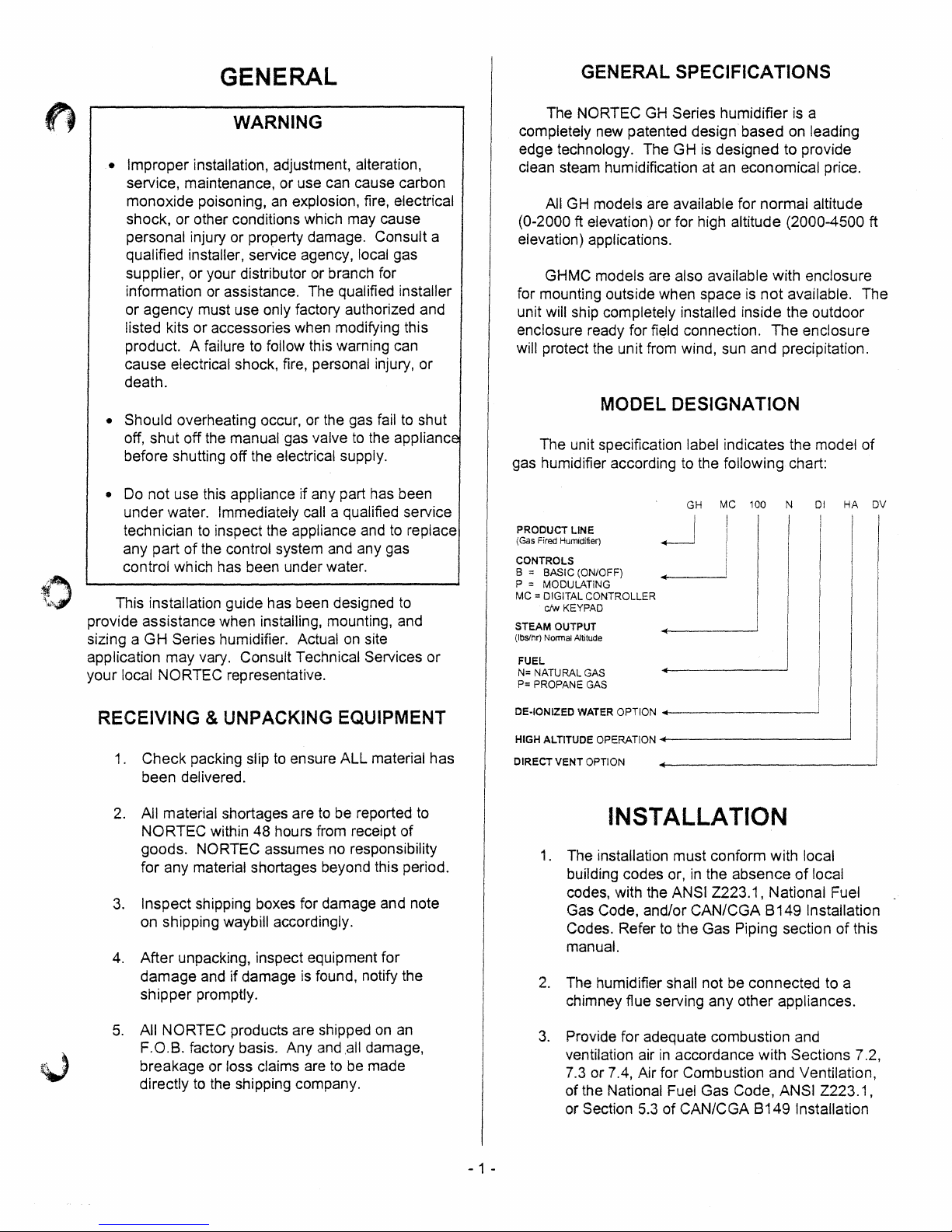
MODEL DESIGNATION
The
unit specification label indicates the model
gas humidifier according to the following chart:
PRODUCT LINE
(Gas Fired Humidifier)
CONTROLS
B = BASIC (ON/OFF)
P = MODULATING
MC = DIGITAL CONTROLLER
cJw
STEAM OUTPUT
(lbSlhr) Normal Altitude
KEYPAD
FUEL
N=
NATURAL
P=
PROPANE GAS
GAS
GH MC 100
~!
of
__
_
:
i
!
I
~
N
01
price.
The
of
HA DV
RECEIVING & UNPACKING EQUIPMENT
1 .
Check
been delivered.
2. All material shortages are to be reported to
NORTEC
goods. NORTEC assumes no responsibility
for
3.
Inspect
on shipping waybill accordingly.
After
4.
damage
shipper
5.
All
F.O.B. factory basis.
breakage
directly to the shipping company.
packing Slip to ensure
within
48
hours from receipt
ALL
material
of
has
any material shortages beyond this period.
shipping boxes for damage and note
unpacking, inspect equipment
and
if
damage is found, notify the
for
promptly.
NORTEC
products are shipped on an
Any
and
,all
or
loss claims are to be made
damage,
DE·IONIZED WATER OPTION
HIGH ALTITUDE OPERATION
DIRECT VENT OPTION
INSTALLATION
1. The installation
building codes or,
codes, with the ANSI
Gas Code, and/or
Codes. Refer to the
manual.
2.
The humidifier shall not be
chimney flue serving
3.
Provide
ventilation air
7.3
of
or Section 5.3
for
adequate
or
7.4, Air
the National Fuel Gas Code, ANSI
+-------~
+-------------'
must
conform with local
in
the
absence
2223.1,
CAN/CGA
Gas
Piping section
any
other
combustion
in
accordance with
for
Combustion
of
CAN/CGA
of
local
National Fuel
B 149 Installation
of
connected
to a
appliances.
and
Sections
and
Ventilation,
2223.1,
B149
Installation
this
7.2,
- 1 -
Page 5
:;~:::::~"7:::::=.';-,",~;::;:-":=~:;:::;::;;:=:~:;;:==::-":===:::::"~:':::'::;::;;::=:::::::;::::::::;."";:!"==:::=:;;:-----:===:::;;..-='"~-===::':=:;:::::::::::--====:.-:;::::~-=:::::=::!:::-..;:;:::=:.;::::::::;!':;;:
MODEL
...
FUEL···
··.·B~~~iRr·iNPUT(BTuH;:··-roR\~i:~iZE
I i I DIAMETER!
i!
I
STO
NATURAL
PROPANE
(LP
.,
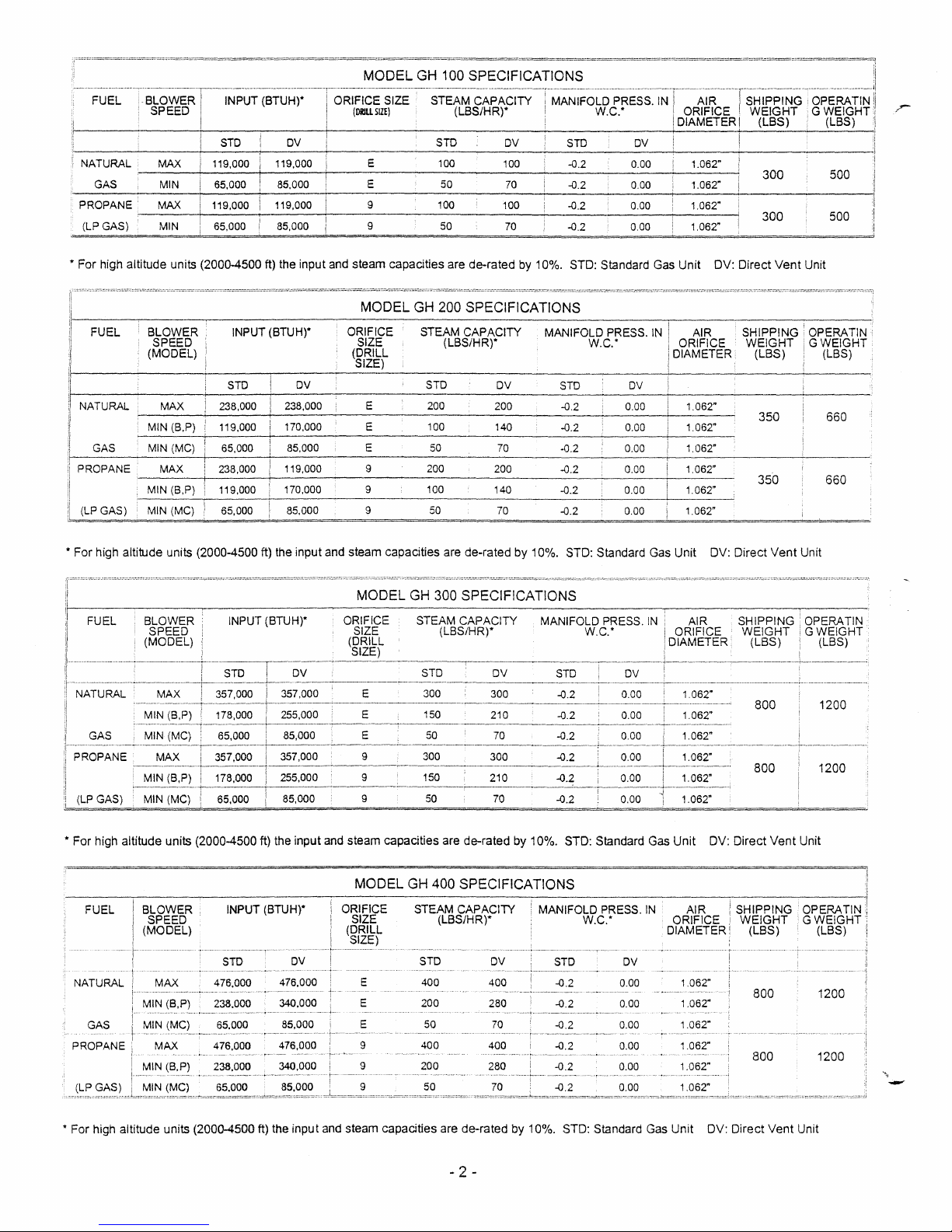
For high altitude units (2000-4500 ft) the input and steam capacities are
FUEL INPUT (BTUH)*
~_MAX
GAS
~-----+------~------~--------------------------~------------~------~
GAS)
i
____
+-_11_9_,0_0_O_!~1_1_9_,0_00
MIN
MAX
MIN
65,000 85,000 E
119,000 119,000 9 100 100
65,000 85,000 9 50 70
OV!
__ ~ ____
E
GH
--ST~£~~F;TYTMANiFOW.t.~ESS;NT~~iic-~Ts.tJT!:~0f~g~mu~i
STD
_________
100 SPECIFICATIONS
OV
100
__ ~ ____
50
10_0
70
de-rated
__ ~ ______________
by 10%.
...
-::::.:::::::::"..:::-::;;:::..""!;:=::-:::=::;::::;:::::~:':::;:::;:::-":!::;:''";:::;:::::::';-"::;::===-":;';;:':=::!;:::--,";=;:::;:::":=:':=:::":~":::::::::-'=;:="':::;1
ii
STO
. i
OV
~
______
(LBS)
~
(LBS) I
.,
For
high altitude units (2000-4500 ft) the input and steam capacities are
FUEL
NATURAL 357,000
GAS
1t
For
high altitude units (2000-4500 ft) the
BLOWER
SPEED ORIFICE
(MODEL)
INPUT (BTUH)"
STO
178,000
65,000
357,000
ov
357,000
255,000
85,000
357,000
input
and steam capacities
are
de-rated
300
210
70
de-rated
by
10%. STD: Standard Gas Unit DV:
DIAMETER
OV
-0,2
-0,2 0,00
-0.2
by
10%. STD: Standard Gas
0,00
0.00 1.062"
0.00
1.062"
1.062"
1.062"
Unit
AIR
DV:
350
Direct
Vent
SHIPPING
WEIGHT
(LBS)
800
800
Direct
Vent
660
660
Unit
OPERATIN
GWEIGHT
(LBS)
1200
1200
Unit
FUEL
NATURAL MAX
GAS
PROPANE
BLOWER
SPEED
(MODEL) DIAMETER (LBS)
MIN
(B,P)
MIN
MAX
MIN
(B,P)
* For high altitude units (2000-4500 ft) the
INPUT (BTUH)*
476,000
238.000
65.000
476.000
238.000
65,000
OV
476,000
340,000
85,000
476,000
340,000
85.000
input
MODEL
E 400
E 200
E 50
9
9 200
9
and steam capacities are
GH
400 SPECIFICATIONS
STEAM CAPACITY
(LBS/HR)*
STD
400
50 70
de-rated
- 2 -
MANIFOLD PRESS.
DV
400
280
70
400
280
STD
-0,2
-0.2
-0.2
-0.2 0.00
by
10%. STD: Standard Gas
W.C:
OV
0,00 1.062"
0.00
0,00
0,00
0.00
IN
AIR
ORIFICE
1.062~
1.062ft
1.062"
1.062ft
1.062"
Unit
DV:
800
800
Direct
Vent
OPERATIN
GWEIGHT
1200
1200
Unit
-
Page 6
Codes, or applicable provisions
of
the local
building codes.
4. The required free area
is:
11
in. sq. (7,000
20
in. sq. (13,000
in. Sq. (19,500
30
in. Sq. (26,000
40
NOTE FOR DIRECT
The combustion supply air opening
the
required to
room where the appliance is
of
supply air opening
2
mm
),
for GH 100
mm7"
for
mm
),
for GH 300
2
mm
),
for
VENT OPTION:
GH
GH
200
400
is
installed since the combustion air
be
requirements will
provided through the inlet
air duct (see installation section).Some
is
ventilation
required for cooling of the
electronic components
NOTE FOR OUTDOOR ENCLOSURE:
Required free area of supply air
is
provided
through the bottom of the unit. Front louvers
in
ensure good air circulation
These louvers should
be
the summer.
blocked for winter
operation.
5.
Cabinet back
to provide combustion air
and
bottom contain air openings
to
the forced draft
blower. Either the back or bottom set of
openings must have at least
to
clearance
allow for adequate combustion
air. For example, if the humidifier
2"
mounted,
clearance must be maintained to
2" (50 mm)
is
floor
the unit's back surface.
6. Excessive exposure
combustion air
to
contaminated
wiii result
in
safety and
performance related problems. Known
contaminates include halogens, ammonia, and
chlorides, excessive dust, lime or dirt. Contact
NORTEC Technical Services if you have any
questions.
not
9.
During installation cover the humidifier
to
prevent any dust or other contaminants from
entering the cabinet when activities such as
drilling are taking place'.
NOTE: Some
combustible. Prior
the area for insulating
installed
in
an
and clear of insulating materials.
after the appliance
insulating materials may
to
installing this appliance examine
be
material. If this appliance
insulated space, it must be kept free
is
installed, it will
If insulation
be
is
added
necessary to
examine the area again.
LOCATING AND MOUNTING
GH
Series humidifiers are designed
(GH
suitable wall
clearance dimensions shown
100 only), GH Stand,
in
this manual are for
reference only and are the minimum required for
maintenance of the humidifier. Local and National
be
Codes should
installation of the humidifier.
consulted prior to final location and
NORTEC cannot accept
responsibility for installation code violations.
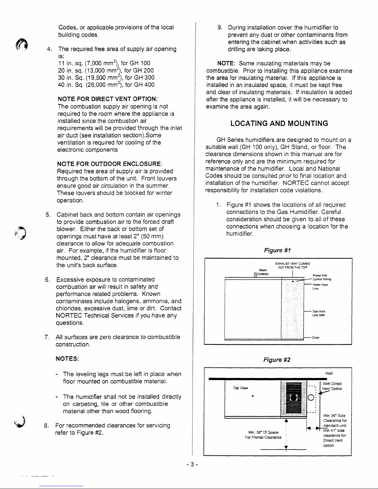
1.
Figure
#1
shows the locations
connections to the Gas Humidifier. Careful
consideration should be given to all
connections when choosing a location for the
humidifier.
Figure
Steam
1=========::::::::o=utJe=t{$=)
#1
EXHAUST VENT
OUT FROM THE
===+~:=:::;;;l--
to
mount
or
floor. The
of
all required
of
these
COMES
TOP
~~::t~ring
Water Input
Line
Gas Input
Line
Side
is
on
a
7.
All surfaces are zero clearance
construction.
NOTES:
- The leveling legs must be left
on
floor mounted
combustible material.
The humidifier shall not
on
carpeting, tile or other combustible
material other than wood flooring.
8.
For recommended clearances for servicing
refer to Figure
#2.
to
combustible
in
place when
be
installed directly
- 3 -
t::::::======::±:==:=f-
Figure #2
Top
View
•
Min, 36" Of Space
For Frontal Clearance i
I
I
T
Drain
Wall
With Direct
clearance
Direct Vent
option
for
Page 7
2. For front and side clearance requirements (for
access during installation, maintenance and
troubleshooting), see Figure #2.
3.
Location
minimum
4.
DO NOT locate humidifier any further than
absolutely necessary from steam distributor
location. Net output
of
Engineering Manual, Form
increased static pressure (over
result
Consult factory if this situation occurs.
5.
Where possible, mount humidifier at a height
convenient for servicing.
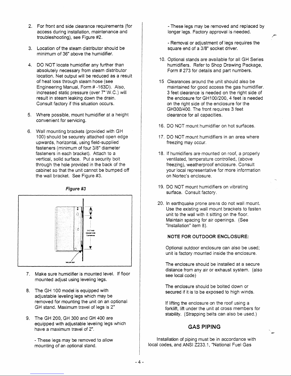
6.
Wall mounting brackets (provided with GH
100) should
upwards, horizontal, using field-supplied
fasteners (minimum of four
fasteners
vertical, solid surface. Put a security bolt
through the hole provided
cabinet so that the unit cannot
the
of
the steam distributor should be
of
36" above the humidifier.
will
be
reduced as a result
heat loss through steam hose (see
# -1630). Also,
7"
W.
in
steam leaking down the drain.
be
securely attached open edge
3/8"
diameter
in
each bracket). Attach
in
wall bracket. See Figure #3.
to
the back of the
be
bumped off
C.) will
a
- These legs may
longer legs. Factory approval is needed.
- Removal or adjustment
square end of a
be
removed and replaced
of
legs requires the
3/8"
socket driver.
10. Optional stands are available for all GH Series
humidifiers. Refer to Shop Drawing Package,
# 273 for details and part numbers.
Form
15
Clearances around the unit should also be
maintained for good access the gas humidifier.
is
3 feet clearance
the enclosure for
on
the right side of the enclosure for the
needed
GH100/200, 4 feet is needed
on
the right side of
GH300/400. The front requires 3 feet
clearance for
16.
DO
NOT mount humidifier on hot surfaces.
17.
DO
NOT mount humidifiers
freezing may occur.
If humidifiers
18.
ventilated, temperature controlled, (above
freezing), weatherproof enclosure. Consult
local representative for more information
your
on
Nortec's enclosure.
ail
capacities.
in
an
area where
are-
mounted on roof, a properly
by
Figure
7.
Make sure humidifier
mounted adjust using leveling legs.
8.
The GH 100 model
adjustable leveling
removed for mounting the unit
GH stand. Maximum travel of legs
9.
The GH 200,
equipped with adjustable leveling legs which
have a maximum travel of
GH
#3
c
is
mounted level. If floor
is
equipped with
legs which may be
on
300 and
GH
2".
400 are
an optional
is
2"
19.
DO
NOT mount humidifiers on vibrating
surface. Consult factory.
20.
In
earthquake prone
Use the existing wall mount brackets
to
the wall with it sitting
unit
Maintain spacing for air openings.
"Installation"
NOTE FOR OUTDOOR ENCLOSURE:
Optional
is
unit
The enclosure should be installed at a secure
distance from any air or exhaust system. (also
see local code)
The enclosure should be bolted down or
secured if it
If lifting
forklift, lift under the unit at cross members for
stability. (Strapping belts can also be used.)
item
outdoor enclosure can also be used;
factory mounted inside the enclosure.
is
the
enclosure
to
are.:Js
8).
be
exposed
do not wall mount.
on
the floor.
to
high winds.
on
the roof using a
to
(See
GAS PIPING
fasten
- These legs may
mounting
of
be
removed
an
optional stand.
to
allow
Installation of piping must
local codes, and ANSI Z233.1, "National Fuel Gas
be
in
accordance with
- 4 -
Page 8

Code,"
Installation Codes
minimum
in
the United States or CAN/CGA-B 149
in
Canada.
The
following table indicates the maximum and
allowable gas pressures for the Gas
Humidifier.
INCHESW.C.
GAS MIN.
Natural
Propane
•
The gas inlet pipe size
~"NPT
for GH 100
3/4" N PT for
1"
NPT for GH300/400
Provide
an
adequate size gas supply line.
When black iron
be
must
In
located ahead of the humidifier gas controls.
all installations, a manual shut off valve, located
outside the cabinet, must
GH
gas
4.5
,
9.0
to
the appliance is:
200
pipe
is
used, a sediment trap
be
installed. See Figure #4.
MAX.
14.0
14.0
Figure #4
NOTES:
1.
Failure
the gas valve.
not covered
2.
DO
threads. A flexible
with Natural Gas and Propane Gas
to
follow this procedure may damage
Over pressured gas valves are
by
warranty.
NOT use Teflon tape
on
gas line pipe
sealant suitable for use
is
recommended.
3.
Plan
gas
supply piping so it will not interfere
with removal of gas valves or blower
assemblies
The gas valve
and
front or side service doors.
is
provided with pressure taps to
measure gas pressure upstream and downstream,
(manifold pressure). The minimum gas pressure
is
shown
for the purpose
A
1/8" NPT plugged tapping, accessible for test
of
input adjustment.
gage connection, must be installed immediately
upstream of the gas supply connection to the
appliance. The humidifier
shall not be connected to a
chimney flue serving any other appliances.
NOTE FOR OUTDOOR ENCLOSURE: Gas lines
should
routed through the bottom
of
the enclosure
be
For direct vent units, the combustion supply air
is
opening
appliance
not required
is
installed since the combustion air
requirements will
(see installation notes below). Some ventilation
required for cooling
to
the room where the
be
provided through the inlet air duct
of
the electronic components
is
,J
Leak test all gas connections using a commercial
to
soap solution made
gas leakage.
humidifier
Seal
in
operation.
WARNING: Never use
gas leaks.
If a leak does exist, a fire or explosion
could occur, resulting
detect leaks. Bubbles indicate
all
leaks before placing the
an
open flame
in
damage, injury or death.
to
check for
The appliance must be isolated from the gas
by
supply piping system
closing its individual manual
shut-off valve during any pressure testing of the gas
supply piping system at test pressures equal to
greater than 14"
W.c.
(3.5 kPa).
or
Dissipate test pressure from the gas supply line
before re-opening the manual shut off
valve to the
appliance.
AIR MANIFOLD/CONNECTOR HOSE
INSTALLATION FOR DIRECT
All direct vent units are shipped with the air
manifold and connector hoses packaged separately.
The connector hoses and air manifold must be
installed by a qualified installer prior to commissioning
the unit.
Figure #5
- 5 -
VENT
Hose
u:uUlcclion
iApply
iiliccne)
Page 9
Procedure:
1. Apply a ring of silicone around the outside
each
of
the blower adapter connector.
2.
Mount a flexible connector hose
connection
secure using a gear clamp provided with the
unit. Care should be taken not to kink
damage
3.
Carefully bend the flexible hose(s) to give the
"S" shape
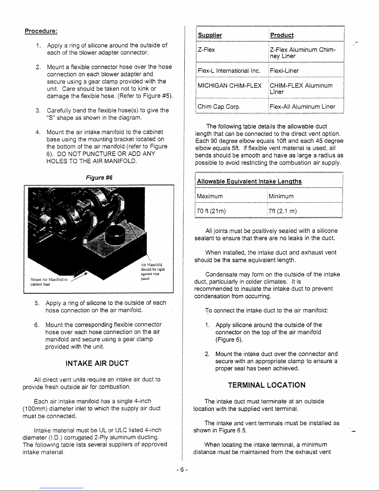
4.
Mount
base using the mounting bracket located on
the bottom
6).
DO
HOLES
on
each blower adapter and
the flexible hose. (Refer to Figure #5).
as
shown
the air intake manifold to the cabinet
of
NOT
PUNCTURE OR ADD
TO THE AIR MANIFOLD.
in
the diagram.
the air manifold (refer to Figure
over
the
or
ANY
of
hose
•.
1.·11-1
S_U_p_p_li_e_r
: Z-Flex I Z-Flex
II
Flex-L
'I
I MICHIGAN CHIM-FLEX
:
I
il-~~i~-~-~~-~:~~~-
:b~~~"'~==o~"==,~=~"~~:.c.="'''o,''~==o,,'o,'''~~o,,'''=,~o,,,c."~=~~~,=,c.,,~~=="""="""='"'~=~"',,Jj
length that can be connected to the
Each
elbow equals
bends should be smooth and have as
possible to avoid restricting the
______
International_l~ll~~iner
-·--·T~I:~_~I;~~~~=~·-~~~e~--'I
The following table details the
90 degree elbow equals 10ft
Sft.
If flexible vent material is used, all
i
t.-
P_r_o_d_u_c_t
Iney
i '
',,:
CHIM-FLEX
'Liner
______
Aluminum
Liner
~
Aluminum
allowable
direct
and
each
large
combustion
Chim-
___
duct
vent
option.
45
degree
a radius as
air supply.
:1
[I
i,i
III
i
Figure #6
cabinet base
5.
Apply
a ring of silicone to the outside
hose
connection on the air manifold.
6.
Mount
hose
manifold and secure using a gear clamp
provided with the unit.
the corresponding flexible
over
each hose connection on
INTAKE AIR DUCT
against rear
panel
of
each
connector
the
air
rl
Allowable Equivalent
I Maximum i
I '
I
:170
ft
(21
!
sealant to ensure that there are no leaks in
should be the same equivalent length.
duct, particularly
recommended to insulate the intake
condensation from occurring.
m) : 7ft (2.1
All jOints must be positively sealed
installed, the intake
When
Condensate may form on the outside
in
To connect the intake duct to
1.
Apply silicone around the outside
connector on the top
(Figure 6).
2.
Mount the intake duct
secure with an appropriate clamp to
proper seal has been achieved.
Int~ke
colder climates. It is
Lengths
Minimum
m)
duct
and
duct
the
air manifold:
of
the air manifold
over
the
with
exhaust
to prevent
connector
a silicone
the
duct.
of
the intake
of
the
ensure
~
vent
and
a
ii
All direct
provide fresh outside air for combustion.
Each air intake manifold has a Single 4-inch
(1
OOmm)
must
be connected.
Intake material must be UL or ULC listed 4-inch
diameter
The
following table lists several suppliers
intake
vent
units require
diameter
(1.0.) corrugated 2-Ply aluminum ducting.
material.
inlet to which the supply air
an
intake air
duct
duct
of
approved
to
TERMINAL LOCATION
The intake duct must terminate at an outside
location with the supplied vent terminal.
The intake and vent terminals
in
shown
distance must be maintained from the
- 6 -
Figure 6.5.
locating the intake terminal, a
When
must
exhaust
be
installed as
minimum
vent
Page 10
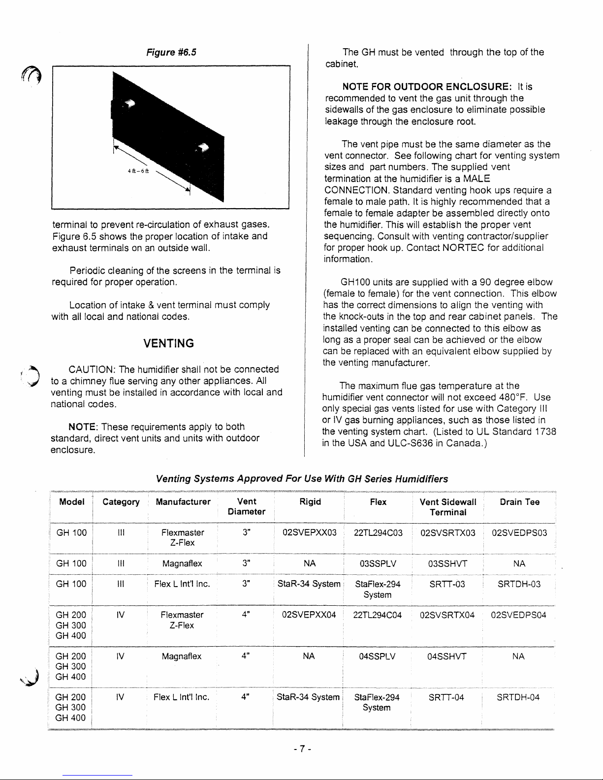
Figure #6.5
The
cabinet.
GH
must be vented through the top of the
terminal
Figure 6.5 shows
exhaust terminals
to
prevent re-circulation
the
proper location
on
an
outside wall.
of
Periodic cleaning of the screens
exhaust gases.
of
intake and
in
the terminal
required for proper operation.
Location
of
intake & vent terminal must comply
with all local and national codes.
VENTING
CAUTION: The humidifier shall not be connected
to
a chimney flue serving any other appliances. All
venting must be installed
national codes.
NOTE: These requirements apply to both
standard, direct vent units and units with outdoor
enclosure.
in
accordance with local and
is
NOTE FOR OUTDOOR
recommended
sidewalls
to
vent the gas unit through the
of
the gas enclosure to eliminate possible
ENCLOSURE:
It
is
leakage through the enclosure root.
The vent pipe must be the same diameter
vent connector.
and
sizes
part numbers. The supplied vent
See following chart
for
as
the
venting system
termination at the humidifier is a MALE
CONNECTION. Standard venting
to
female
female
male path. It is highly recommended that a
to
female adapter be assembled directly onto
hook
ups require a
the humidifier. This will establish the proper vent
sequencing. Consult with venting contractor/supplier
for proper hook up. Contact
NORTEC for additional
information.
GH100 units are supplied with a 90 degree elbow
to
(female
has the correct dimensions
the knock-outs
installed venting can be connected to this elbow
long
can
female) for the vent connection. This elbow
to
align the venting with
in
the top and rear cabinet panels. The
as
a proper seal can
be
replaced with
be
achieved
an
equivalent elbow supplied
or
as
the elbow
the venting manufacturer.
The maximum flue gas temperature at the
humidifier vent connector
only special gas vents listed for use with Category
or
IV
gas burning appliances, such as those listed
the venting system chart. (Listed to
in
the USA
and
ULC-S636
will not exceed 480°F. Use
III
in
UL
Standard 1738
in
Canada.)
by
,.J
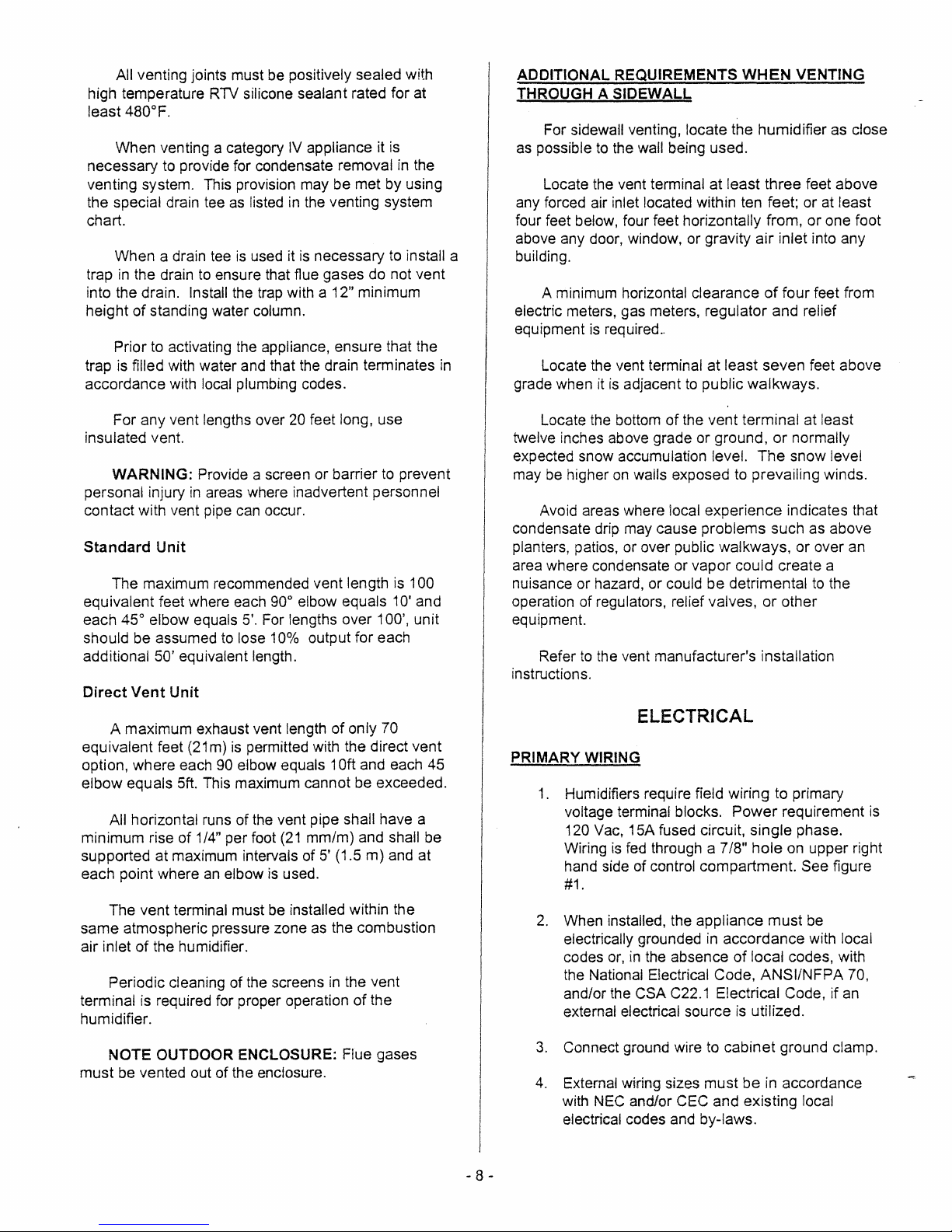
Venting
Model
GH 100
GH
100
GH 100
GH 200 IV Flexmaster
GH 300
GH
400
GH 200
GH 300
GH400
GH 200
GH 300 System
GH 400
Category
III
III
III
IV
IV
Manufacturer
Flexmaster
Magnaflex
Flex L Int'I Inc.
Magnaflex
Flex L Int'I Inc.
Z-Flex
Z-Flex
Systems
Diameter
:
Approved
Vent
:
3"
3"
3"
4"
4"
4"
StaR-34 System
For
Use With
Rigid
02SVEPXX03
NA
StaR-34 System:
02SVEPXX04
NA
GH
Series Humidifiers
Flex
i
22TL294C03 02SVSRTX03 02SVEDPS03
03SSPLV
:
StaFlex-294
System
22TL294C04 02SVSRTX04 02SVEDPS04
04SSPLV
StaFlex-294 SRTT-04
- 7 -
Vent
Terminal
03SSHVT
.
SRTT-03
04SSHVT
Sidewall
Drain
Tee
NA
SRTDH-03
NA
SRTDH-04
Page 11
All venting joints must
high temperature
480°F.
least
When venting a category
necessary
venting system. This provision may be met by using
the special drain tee
chart.
When a drain
trap
in
the drain
into the drain.
of
height
trap
accordance with local plumbing codes.
standing water column.
Prior
to
is
filled with water and that the drain terminates
RTV
to
provide for condensate removal
tee
to
ensure that flue gases do not vent
Install the trap with a 12" minimum
activating the appliance, ensure that the
be
positively sealed with
silicone sealant rated for at
IV
appliance it
as
listed
in
the venting system
is
used it
is
necessary
is
in
the
to
install a
in
ADDITIONAL REQUIREMENTS
THROUGH
For sidewall venting. locate the humidifier as close
as
possible
Locate the vent terminal at least three feet above
any forced air inlet located within ten feet; or
four feet below, four feet horizontally from, or one foot
above any door, window, or gravity air inlet into any
building.
A minimum horizontal clearance
electric meters, gas meters, regulator and relief
equipment
Locate the vent terminal at least seven feet above
grade when it
A SIDEWALL
to
the wall being used.
is
required
is
..
adjacent
to
WHEN
public walkways.
VENTING
of
four feet from
at
least
For any vent lengths over
insulated vent.
WARNING: Provide a screen or barrier
personal injury
contact with vent pipe
Standard Unit
The maximum recommended vent length
equivalent feet where each 90° elbow equals
45° elbow equals
each
should be assumed
additional
Direct Vent Unit
A maximum exhaust vent length
equivalent feet (21m)
option, where each
elbow equals 5ft. This maximum cannot be exceeded.
All horizontal runs of the vent pipe shall have a
minimum rise of
supported at maximum intervals of
each point where
The vent terminal must be installed within the
same atmospheric pressure zone
air inlet
terminal is required for proper operation
humidifier.
of
Periodic cleaning of the screens
in
areas where inadvertent personnel
can
5'.
to
lose 10% output for each
50' equivalent length.
is
90
elbow equals 10ft and each 45
1/4" per foot
an
elbow
the humidifier.
20
feet long, use
to
prevent
occur.
is
100
10'
and
For lengths over 100', unit
of
only 70
permitted with the direct vent
(21
mm/m) and shall be
5'
(1.5 m) and at
is
used.
as
the combustion
in
the vent
of
the
of
Locate the bottom
twelve inches above grade or ground,
expected snow accumulation level.
may
be
higher
on
walls exposed
Avoid areas where
condensate drip may cause problems such as above
planters, patios, or over public walkways, or over
area where condensate or vapor could create a
nuisance or hazard, or could be detrimental
operation of regulators, relief valves, or other
equipment.
Refer
to
the vent manufacturer's installation
instructions.
the vent terminal at least
or
normally
The
snow level
to
prevailing winds.
local experience indicates that
an
to
the
ELECTRICAL
PRIMARY WIRING
1.
Humidifiers require field wiring to primary
voltage
120 Vac, 15A fused circuit, single phase.
Wiring
hand side of control compartment.
#1.
2.
When installed, the appliance must
electrically grounded
codes
the National Electrical Code, ANSI/NFPA 70,
and/or the CSA
external electrical source
terminal blocks. Power requirement
is
fed
through a 7/8" hole
or,
in
the absence
C22.1
in
accordance with local
of
Electrical Code, if
is
on
upper right
See figure
be
local codes, with
utilized.
an
is
NOTE OUTDOOR ENCLOSURE: Flue gases
be
must
vented out of the enclosure.
- 8 -
3.
Connect ground wire to cabinet ground clamp.
4.
External wiring sizes must be
with
NEC
and/or CEC and existing local
electrical codes and by-laws.
in
accordance
Page 12
NOTE FOR OUTDOOR ENCLOSURE:
- Primary power should be routed through the grille at
the
the bottom of
If backup heater
-
unit.
is
used, separate 240 supply must be
provided with disconnect brought to the Enclosure for
20A-
the heater. (Heater uses
wiring size)
heater for instructions
See installation drawing provided with the
on
be plugged into 3-pronged,
If units operates during the summer, wire exhaust fan
-
consult local codes for
page 32. Note: Heater may
30
ampere, 240 V outlet.
provided with the enclosure (120Vwires supplied with
enclosure). Exhaust fan power can be the same sup-
to
ply then the power
LOW
VOL
rAGE
the unit.
CONTROL WIRING
B - Duct Mounted Safety High Limit On/Off
Humidistat: Wired
on
rise
to
safety setpoint. Set to approximately 85%
RH
as
a safety to prevent saturation and wetting
to
make on drop
in
humidity, break
in
duct. Highly recommended for ducted applications.
C - Duct Mounted Safety Air Proving On/Off
Switch:
Wired to make when sensing air flow, break
when no air flow. Used as a safety to prevent
is
saturation when there
no air flow. Highly
recommended for ducted applications.
D&E Humidistat: Provides a modulating signal
that represents the output
the
humidifier. Refer
the
signal ranges that can be used with each model.
Wall or Duct Mounted Modulating
to
(up
to 100%) required from
to
the sections below that detail
the unit
the
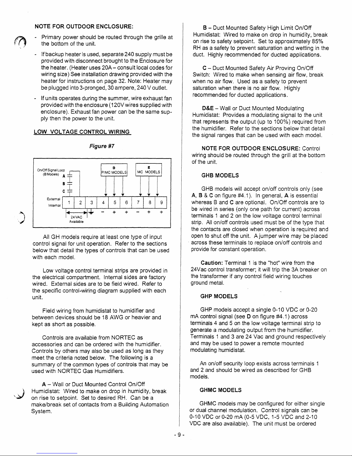
Figure #7
On/Off Signal Loop
(BModels)
A
sI
-r
C.l
External
Internal
~~
__
~~
__ ~ __
Available
All GH models require at least one type
control signal for unit operation. Refer
below that detail the types of controls that can be used
with each
model.
Low voltage control terminal strips are provided
the electrical compartment. Internal sides are factory
wired. External sides are to
the specific control-wiring diagram supplied with each
unit.
Field wiring from humidistat to humidifier and
between devices should be
kept as short
as
possible.
Controls are available from
can
be
accessories and
ordered with the humidifier.
Controls by others maya/so
meet the criteria noted below. The following
of
summary
used with
A -
Humidistat: Wired
on
rise
make/break set
the common types
NORTEC Gas Humidifiers.
Wall or Duct Mounted Control On/Off
to
make
on
to
setpoint. Set to desired
of
contacts from a Building Automation
System.
~~
__ ~ __
to
the sections
be
field wired. Refer
18
AWG or heavier and
NORTEC as
be
used as long as they
of
controls that may be
drop
in
humidity, break
RH.
Can be a
of
is
L-~
input
to
a
in
NOTE FOR OUTDOOR ENCLOSURE: Control
wiring should be routed through the grill at the bottom
of the unit.
MODELS
GHB
GHB models will accept on/off controls only (see
A,
B & C
on
figure #4.1).
Band
whereas
be
wired
terminals 1
C are optional. On/Off controls are
in
series (only one path for current) across
and 2 on
strip. All on/off controls used must be
the
contacts are closed when operation
to
open
across these terminals to replace on/off controls and
.
shut off the unit. A jumper wire may
In
general, A
is
essential
the low voltage control terminal
of
the type that
is
required and
be
placed
provide for constant operation.
Caution: Terminal 1 is the
24Vac control transformer; it
the transformer if any control
"hof'
wire from the
will trip the 3A breaker on
field wiring touches
ground metal.
MODELS
GHP
GHP models accept a single 0-10 VDC or 0-20
mA
control signal (see D
terminals 4
and 5 on
on
figure #4.1) across
the low voltage terminal strip to
generate a modulating output from the humidifier.
and
Terminals 1
and
may be used
3 are 24 Vac and ground respectively
to
power a remote mounted
modulating humidistat.
An
on/off security loop exists across terminals 1
and 2 and
should be wired as described for GHB
models.
GHMC
GHMC models may
or dual channel modulation. Control signals
0-10
VDC
MODELS
be
configured for either single
VDC
or 0-20 mA (0-5 VDC, 1-5 VDC and 2-10
are also available). The unit must
be
ordered
can
be
to
- 9 -
Page 13
from the factory for the desired signal type and number
of
channels. When configured for 2-channel
modulation the humidifier will generate steam only
if
both channels indicate a demand (see O&E on figure
#4.1).
humidifier will satisfy the lower demand
If both channels are demanding steam the
signal.
do not have a built-in air distribution system.
Blowers are remote mounted only.
2.
Blower packs are remote mounted only. See
Blower Pack Manual XX-277 for requirements
and installation instructions.
An on/off security loop exists across terminals 1
and 2 and should be wired as described for GHB
models.
CONTROL INSTALLATION
1.
Mount any wall humidistat (control or high
limit) over standard electrical box at height
similar to typical thermostat. Any wall
in
humidistat should be
of
overall space being humidified and not
path
of
blower pack or air supply grille. Do
mount
on
an
outside wall where temperature
fluctuations can affect control response.
2.
Mount duct humidistat
representative of overall air humidity, usually
in
return duct.
of
steam distributor or
Do
zone. Mount humidistat where air's humidity
and temperature are uniform and
representative of spaces being humidified.
3.
Mount duct high limit humidistat downstream
of
steam distributors far enough that, under
normal humidity and air flow conditions, steam
will have been fully absorbed (typically at
feet). It must be located to sense high
10
humidity only when uniform and representative
air is over-humidified or approaching
saturation.
location representative
in
location
not mount
in
turbulent
it
directly
or
in
mixing
in
not
front
least
STEAM DISTRIBUTORS FOR DUCTED
APPLICATIONS
1.
Any humidifier's steam line may be divided
into multiple branches to feed more than one
distributor.
common copper fittings that are available for
this purpose.
of the steam supply lines.
2.
Steam distributor locations are typically as
follows: supply air duct, return air duct, air
handling unit. Proper location should
consider: air temperature, relative humidity
before the distributor, air velocity, dimensions
of the location, amount
introduced into the duct, downstream
obstructions, and surfaces vulnerable to
wetting.
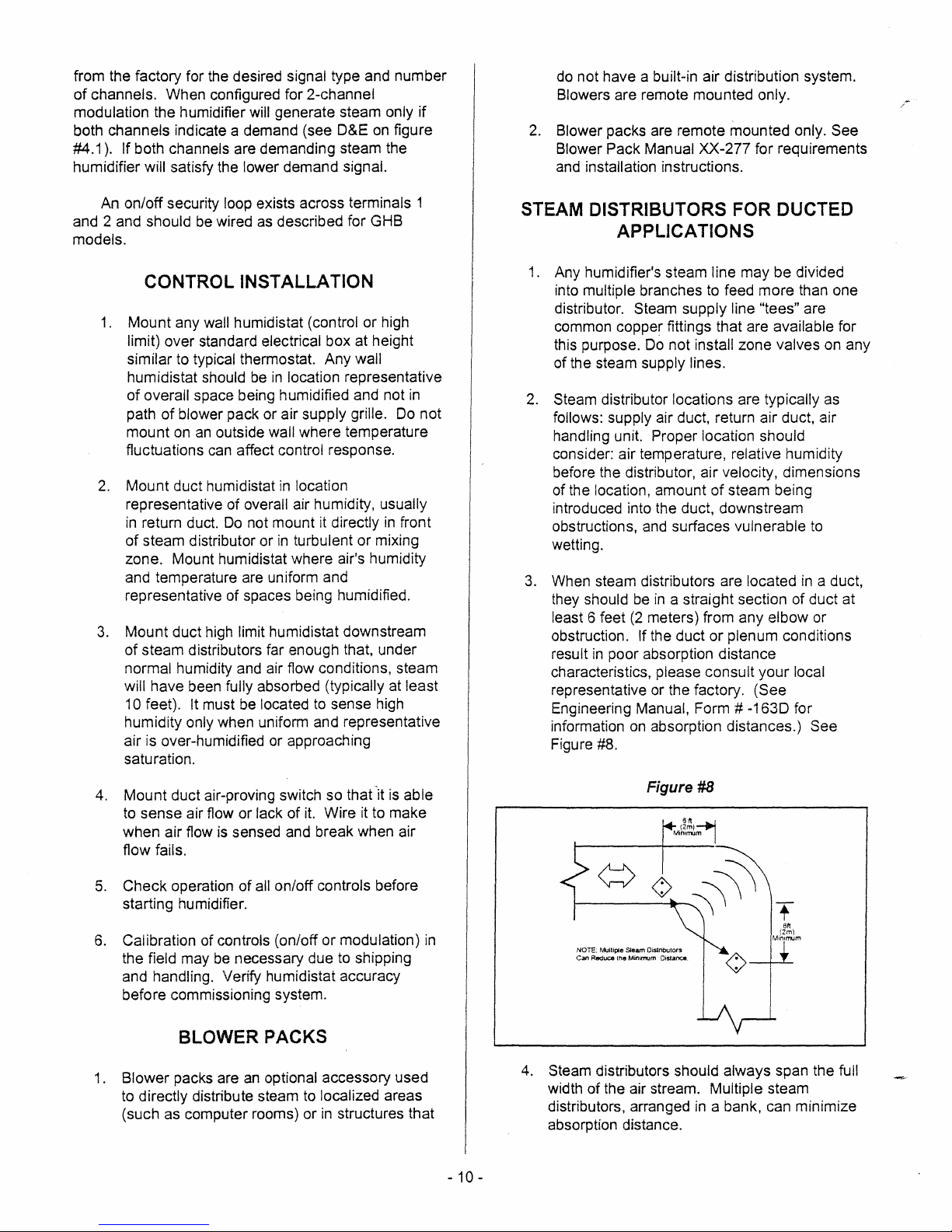
3.
When steam distributors are located
they should be
least 6 feet
obstruction.
result
characteristics, please consult
representative or the factory. (See
Engineering Manual, Form #
information
Figure #8.
Steam supply line "tees" are
Do
not install zone valves on any
of
steam being
in
a straight section of duct at
(2
meters) from any elbow or
If the duct
in
poor absorption distance
on
absorption distances.) See
or
plenum conditions
your
-1630
in
local
for
a duct,
4. Mount duct air-proving switch so that
to sense air flow or
when air flow
lack of
is
sensed and break when air
it.
flow fails.
5.
Check operation
of
all on/off controls before
starting humidifier.
6.
Calibration of controls (on/off
the field may be necessary due to shipping
and
handling. Verify humidistat accuracy
before commissioning system.
BLOWER PACKS
1 . Blower packs are
to directly distribute steam to localized areas
(such as computer rooms) or
an
optional accessory used
-it
is able
Wire it to make
or
modulation)
in
structures that
in
Figure
NOTE: MuUipie Steam Oislnbutors
Can Reduce
tile
Minll"l1Um
4.
Steam distributors should always span the full
width
of
the air stream. Multiple steam
distributors, arranged
MinlrnJm
Distance.
#8
(2m)
6n~
in
a bank, can minimize
absorption distance.
10-
-
Page 14

I~
. (
'J
5.
Exercise extreme caution when installing
fiberglass or internally lined ducts. If
necessary, remove 4-6 feet of the lining where
the steam
6. High positive or negative static pressure ducts
or plenums have special requirements. High
positive static pressure ducts may require the
unit
water trap.
7.
Low temperature ducts below 60°F (15°C),
shallow ducts, or branch ducts might require
the use of a field supplied condensate drain
pan below the steam distributor.
to
is
being introduced.
be
fitted with
an
extended external
See Figure
in
#9.
rod through top or bottom of duct. See Figure
#11.
Figure
#11
3/8' Ttveaded
(Field
SuWied)
lbd
~
Hex
Nut
Duct
Steam DiStlibutor
(Factory SuWlied)
,)
Drain Pan
T·SarCeiling
Figure
#9
~~L
¢J~
! .....:...
DrainPan
8.
The steam distributor mounting plate
perpendicular to the steam distributor. When
the mounting plate
the duct, the distributor
downward slope
poor condensate drainage and "spitting"
condensate
in
duct. See Figure #10.
~o
~
I
is
attached
is
to
the distributor will result
level.
to
the side
An
is
of
upward or
in
of
10. Using duct mounting template provided, cut a
hole
in
side of duct just large enough
steam manifold and condensate drain pipe
assembly. Use four sheet metal screws
attach mounting plate
Figure #12
1.
1.
Steam Distributor Mounting Plate
2.
Cut
3.
Mount
and
, Figure #12
Hole In Duct For Insertion Using Template
With Four Sheet Metal Screws
Figure #13
#13.
2.
to
side
of
to
admit
to
duct. See
3.
Figure #10
~
I
~
=-'-1
1,
,)
Any distributor longer than 3 feet
9.
be
should
supported at its end with a threaded
I-
Always
I~
:;:::J
1-
Mount
Level
(1
meter)
,
..
§J~,,
__
,]:t~!~,_
..
___
..
A_,
__ , ______
~.,.
__
: ASD
8"
14"
4.125" 3.875":
8.25" 5.15"
rBs'D-"--TO"-"---4:875;i--4~1'25":
CSD
,
~
~
._-------_
..............
_-_
..
_-_
..........
_
....
---_
...
_
..........
,
,S.D. H min. A B
ASO--6"--'"3-:-ZS';;----Z:7f?'''
BSD
8" 5.125" 2.875"
'CSU--12·----7~6·25"--4~375"'·
-
11
-
-
Page 15

11. It is recommended that single distributors are
mounted near the bottom of the duct
is
the steam
dispersed into the majority
to
ensure
of
the
air flow. See Figure #13.
WATER SUPPLY LINE
1.
The humidifier
potable tap water.
is
intended to operate
on
cold
12. With multiple steam distributors, the top steam
distributor should
duct to avoid possible condensation
surface
below
of
duct. The remainder
is
proportioned accordingly. See Figure
be
at least 8" below top
of
of
on
space
#14. For short steam absorption systems see
Figure #15.
Figure #14
MIN.
H-16"
MIn.W-12"
H2O"
W17"
2.
DO NOT use a hot water source to
humidifier. Minerals
surfaces and the fill valve's
will adhere more easily to
small flow
su
regulating orifice could become plugged.
3.
Consider using a water softener. Longer
operating times between tank cleaning
reached
4.
Reverse osmosis (RO) water can provide very
long times before cleaning
is
on
softened water.
is
required since it
cleaner than softened water. However,
also more corrosive. Consult factory before
using. Deionized
specific models. Consult
(01)
water may be used with
NORTEC
rep resentative.
Figure #16
Control Circuit
Water Connection
-rr==:::::~~'"
pply the
will be
it
is
Figure #15
/ Steam Header
PLUMBING
NOTE: All water supply and drain line
connections should
local plumbing codes.
NOTE FOR OUTDOOR ENCLOSURE: Water
supply should be routed through the bottom
the enclosure. If freezing conditions occur, water lines
must be heat traced
be
installed
up
to
in
the unit.
accordance with
grille
of
Gas Connection
Drain Connection
5.
Standard fill valves are sized for water
30 to
80
pressure ranging from
to
60
psig). For other pressures, consult
psig (ideally
factory. This pressure should be measured at
the humidifier if the water pressure is suspect.
6.
ALWAYS supply
the water supply line dedicated
humidifier
copper
to
within 4 feet of the humidifier.
Reduce copper
and
install a shut off valve
to
facilitate servicing. Use
to
3/8"
00
and connect
to
the
%"
factory-supplied 3/8" olive compression fitting
on
the side of the humidifier.
NOTE FOR OUTDOOR ENCLOSURE:
Manual shut off valve should be provided both
at the unit and inside the building for additional
safety if freezing condition may occur.
00
to
55
in
the
-
12-
Page 16

DRAIN LINE
1.
The humidifier is equipped with a 1" NPT drain
outlet connection
See Figure #16. A field-supplied funnel is
recommended.
prevent backup due
badly installed drain lines.
2.
The drain line should not
frequently by personnel, or where plumbing
codes prohibit
equivalent for safety reasons, since drain
water from humidifier
Sump/Condensate pumps are available (refer
to Engineering Manual Form #XX-261) if
appropriate drain
on
the side
See Figure #17. It will
to
partially blocked
end
it.
Route
to
a floor drain or
can
be very hot.
is
not available.
Figure #17
RECOMMENDED
of
the humidifier.
or
in
a sink used
an
Figure #18
To
Drain
Figure #19
Fiekt Supplied 1"""laled
Hard Copper Pipe
CI'
Flexble $learn Hose
Avaliable From F
Min.
10
Degree Slope
Min.
adory
3'
3.
Keep drain lines
drain lines sloped down, not
since low spots
sediment and cause backup. The drain line
should
not use
factory.
NOTE FOR OUTDOOR ENCLOSURE:
Humidifier must not
-
- If freezing condition occur, drain lines should
be heat traced.
STEAM LINE
Copper Reducer
As
Funnel Drain
To
SeNe
(By
Others )
NOTE: Drain Nipple
as
Should
short
Not
Reach
Bottom Of The Funnel.
as
possible. Keep
level and not up
in
drain lines will accumulate
be
1"
0.0.
copper pipe or larger. Do
plastic pipe for drain lines. Consult
be
drained
on
the roof.
3'min.
2.
Do
not install zone valves on steam lines.
Improper'adjustment
will over-pressurize the
gas humidifier
3.
NORTEC steam supply hose
be
piping should
steam distributors
should
to
be
promote_condensate runback. See Figure
#18. If this slope
sloped downwards from the
to
the humidifier. Slope
at
least 2"
in
is
not possible, condensate
or
12"( 10 degree slope)
must be removed before the distributor.
Figure #20
Figure #20
-
I
y
..
field-supplied
See
1.
Field-supplied hard copper with %" thick (min.)
insulation
with
is
recommended for'steam supply,
NORTEC supplied steam hose coupling
used to make connection
Figure #18.
to
humidifier. See
-
13-
"-
rt
Condensate
To
Drain
Page 17

4. Minimize the length of steam line and keep it
as straight as possible, minimizing bends.
Avoid using
use
long radius turns (using tube
oversized copper or pairs of
will reduce the condensate generated by
90° elbows. Wherever possible,
bender
on
45° elbows). This
heat
loss. This will also reduce the back pressure
and avoid the need
water
trap.
5.
Ensure that the steam hose does not kink
sag.
The
steam hose becomes more flexible
when
hot. The hose should be supported to
prevent
water traps. Only use steam hose
connections or steam line runs
less. See Figure
to install an extended
of
5 feet
#21
.
or
for
or
Figure #22
er
...
AF
....
Lew Poinl10
n.
Steam Un
.......
Al'f)roac:ft
R_~
The
o..,buDf
Wh
From Abo
__
...
,
Figure
#21
6. To ensure odor-free steam, always use
NORTEC
steam hose. Check steam hose
and hose couplings periodically for cracks,
breaks, kinks. Replace as required.
substitute hose. NORTEC
is
not responsible
DO
for health effects or damage from substitute
hose.
Steam
7.
1-1/2") copper pipe.
than
to
8. Do not use steel or
distribution or hose other than
lines require 1-5/8"
F-or
40
feet use insulated nominal 2"
ensure
the draining
of
plastic pipe for steam
0.0.
(nominal
steam runs longer
copper
condensate.
NORTEC
supplied. Substitution will void warranty.
If
steam
9.
or
humidifier, a condensate trap
line
is
routed below steam distributor
if
the
steam distributor is lower than the
"tee" will
required to remove water at this low point.
Run condensate from trap to nearest drain
lower
than the distributor. See Figure #22.
10. Do
not
run steam line more than
'1
foot per
Ib/hr output. Example, 10 Ibs/hr should
have
a steam run longer than 10 feet. If long
runs are unavoidable. the humidifier should be
sized larger to compensate for condensate
be
not
NOT
losses and insulated copper should definitely
be used.
NOTE
FOR
recommended
the enclosure and the building
specifically if freezing conditions may
unit
occur.
WATER
1.
TRAP
The
GH
atmospheric pressure. Pressure head must
develop
into air duct.
2.
Combined resistance
pressure and steam
small pressure head in
amount of positive static
reflected directly by water column differential
that develops
3.
The built in water trap allows a
12" W.C. pressure before
through drain. This pressure should not be
exceeded
4. Static pressure
distributor's steam outlets are
downflow duct
CONDENSATE
DISTRIBUTORS
1.
Nortec steam distributors and
have built-in connections for draining
condensate. These condensate lines
connected to the nearest floor drain
condensate pump (available from
A flexible condensate hose, (available from
OUTDOOR
to
insulate
Series humidifier
to
push steam through
of
line resistance creates a
water
in
the built in
..
is
usually
applications.
RETURN LINES
ENCLOSURE:
steam
produces
lines between
or
air
handling
steam
supply
duct
positive static
tank. Total
pressure
water
head
trap.
maximum
steam
higher
FOR
escapes
when
faced
STEAM
into
blower
or
NORTEC).
It is
line and
is
of
packs
off
must
to a
at
be
- 14 -
Page 18

NORTEC), may be used for short condensate
runs.
2. Always incorporate a trap
routing
of
in
condensate return line. Condensate that
in
accumulates
steam escaping. Depth
duct static pressure
trap will prevent possibility
of
trap must exceed
in
inches
of
water column.
See Figure #23.
Figure #23
Depth
Of
Trap
My"
2" More Than
Condensate Trap
Must
Be
Static Pressure
Duct
of
On
initial startup, the solenoid operated water fill
valve opens
level reaches float
and
fills the water tank. When the water
"8", see Figure #24, a call for
humidity will initiate the firing sequence. The water fill
continues
until float "A"
is
reached. Float "A" will
initiate a variable time delay relay which maintains
of
water flow for a preset amount
portion of this time the water
exceed the level
of
the blowdown and water will flow
time. During a
level
in
the tank will
down the drain until the timed cycle is complete.
in
During operation, the water level
by
lower
evaporation until float "A" initiates the fill and
the tank will
overflow cycle again.
If the water level'ever falls below float "8" the
burners
will shut down to prevent any damage
to
the
unit.
Figure #24
PULSED
FILL
TO
A
CONSTANT
-f,~-+-~--II:;.f+f
FILL
TO
a
-;~It-+-~:::-~~r-t"~~,,
c~~~~~~~~~~~y
SLOWDOWN
VALVE
1'\
3. Ensure
the
trap
is
3' minimum under the
V steam distributor and has the trap as close to
as
the floor drain
4.
Provide a
when distributor
plenum.
"u"
It
possible.
trap
in
condensate line even
is
located
in
return air
stops a suction action from
impeding condensate flow with duct pressures
below atmosphere.
5.
All condensate return runs must be well
sloped towards the humidifier to ensure
adequate flow.
OPERATION
WATER LEVEL CONTROL
Band
chamber maintains water
cycles through a solenoid operated valve.
water
channel and
second channel. The tank fill incorporates a
(25mm) minimum air gap, to meet plumbing codes.
This fill
humidifier operation.
P Models
A two float switch probe located
level
is
routed into the water tank through one
is
routed
is
isolated from the main tank to enhance
to
the float chamber through a
in
and
controls the fill
a separate float
Cold fill
1"
TANK
Me
Model
A three-float switch probe located
in
a separate
float chamber maintains water level and controls the
cycles through a solenoid operated valve. Cold fill
water
is
routed into the water tank through one
is
channel and
routed
second channel. The tank fill incorporates a
(25mm) minimum air gap,
fill
is
This
isolated from the main tank to enhance
to
the float chamber through a
1"
to
meet plumbing codes.
humidifier operation.
On
initial startup, the solenoid operated water fill
valve opens
level reaches float
and
fills the water tank. When the water
"C", see Figure #25, a call for
humidity will initiate the firing sequence. The water fill
"8"
is
continues until float
is
level
between Float "A" and "8" the fill valve will be
reached. While the water
pulsed for intervals proportional to the demand for
humidity. When the water
valve will
fill
be
disabled.
level reaches Float "A" the
60
seconds after the fill
valve is disabled the drain valve will be activated (for a
fill
- 15 -
Page 19

period
of
0-240 seconds set by programmable
parameter
refer to the
DRN 1). For setting
of
this blow down time,
GHMC Display Manual, form #274.
Figure #25
SEQUENCE OF OPERATION
Provided the necessary power, water, gas and
vent connections are completed, the' unit is started by
the activation
panel.
of
the on/off switch located
on
the front
HIGH WATER LEVEL
OVERFLOW PROTECTION
During this time water will be drained from the top
of
portion
timed
sequence
the tank and blow down the drain until the
cycle
is
complete.
is
The fill valve
until
disabled following the above
water
level
in
the tank drops below float
"B" (due to evaporation). At that time the above
sequence
below
any
is repeated. If the water level ever falls
float "G" the burner(s) will shut down to prevent
damage
to the unit.
AND
When the operating humidistat and
are closed, the ignition module
will energize the igniter.
safety
controls
The hot surface igniter then heats up, and after about
seven seconds, the gas valve
is
energized. The
burner will then be lit and the igniter will stop glowing.
If the burner flame
within 4 seconds, the gas valve
cycle will be repeated a maximum
When the humidity in the
the operating controller, the burners will
the unit
will remain idle until the next call
is
not sensed by the
will shut
of
three times.
space matches the setting
flame
off
and this
shut
for
humidity.
sensor
down and
SLOWDOWN CALIBRATION
The gas humidifier will periodically "blowdown" or
skim water from the tan k to reduce the concentration
of total dissolved solids that accumUlate during long
term operation. Gas Humidifiers are shipped factory
set at maximum blowdown (approximately
output). This setting ensures that scale build-up will
be minimized for
blowdown
all
water conditions.
is
field adjustable. Two parameters will help
determine the proper blowdown setting
Gas-Fired Humidifier
• Water hardness
• Silica content
The
of
20%
amount
the
of
of
of
0..
:I:
(!)
"C
c
<U
CD
:I:
(!)
U
:i
:I:
(!)
*Refer
.
Water Hardness
,
<4 grains
f
.
.
4-10 grains
>10 grains
Water Inspection
Hardness
<4 grains
4-10 grains
!
.............
Semi-Ann ua/
Bi-monthly
to
GHMC
instruction manual for programming instructions.
Interval
Inspection
Semi-Annual
GHMC 100
5
to
10
10 to 14
14+
Interval
Annual
Bi-monthly
GHMC 200
•
·
•
- 16 -
Blowdown
15
to
19
19 to 23
23+
Blowdown
(located on the electrical panel
Potentiometer
All GHB and GHP
Between low & midpoint
Between midpoint and
Maximum
DRN1
Setting
GHMC 300
23 to 28
28 to 32
Setting
behind
the
locked door)
Models
maximum
GHMC 400
33 to 38
38 to 42
Page 20

Due to the wide range
throughout North America it is important that the
A blowdown
f,
conditions. By water conditions we are referring to the
hardness
hardness is measured
important
foaming and contribute to scale buildup
humidifier tank and float chamber. When excessive
foaming occurs,
available from NORTEC.
content
yourself' kits which can
several companies that will perform the tests for a
reasonable price.
municipality for your water condition.
It is possible
observation and guidelines in the tables above. Also,
when high silica content has been identified, the
humidifier tank and float chamber will require
increased maintenance and the blowdown setting
should be increased to maximum setting.
silica content may determine the appropriate
blowdown setting.
is
set according to the local water
of
the water supplied
to
test for silica content. Silicates may cause
an
optional foam separator
If
you are unaware of the hardness or silica
of
your water supply, there are many "do it
You can even contact your
to
reduce this setting according
of
water conditions found
to
the humidifier. The
in
grains per gallon. It
in
be
purchased, or there are
is
the
is
In
this case
also
<\ OUTDOOR ENCLOSURE HEATER
.)
Position
around the heater at around
changes the set-point by
position can be obtained by turning the knob counter
clockwise. The set-point position
#1
SETTING
on
the heater will maintain the air
60 deg.F. Each increment
an
additional 16°F. The off
is
at the 3 O'clock.
to
Prior to filling the unit, it
that no dirt or dust has accumulated
compartment.
contaminants from being drawn into the combustion
blower. All water, gas, electrical and venting
connections must be properly completed and tested
before commissioning the unit.
FILLING THE SYSTEM
Before the GH unit will initiate combustion it must
be
filled with water to the low level setting
controller. (Refer
level
with water, turn the gas supply off and switch the unit
on
at the power switch. The unit will fill automatically
until the
ignition
module(s)
until the fill sequence
power and proceed with the ignition safety shut-off
test.
TESTING THE IGNITION SAFETY SHUT-OFF
by conducting the
will begin. After three tries the ignition
The ignition system safety shut-off must
1.
With the gas supply off, turn power
2.
Blower pre-purges for
NOTE: On mUlti-blower models, it
necessary
If necessary, clean this area
low water level
will lock-out. Leave the unit switched
is
following method
to
wait for all blowers to cycle.
3. After seven seconds the gas valve
energized for four seconds, then de-energized.
After three
pre-purge) the unit goes into a safety lockout.
trials for ignition (complete with
is
necessary to ensure
in
the control
to
prevent
of
the water
to
water level control). To fill
is
reached and then trial for
on
complete. Then switch off the
be
tested
of
test:
on.
30
seconds .
is
is
MANUAL
B
Models
Manual rate adjustment for GHB units
accomplished by rotating the output adjustment
selector that
locked door
clockwise to increase output and counter clockwise to
decrease output.
STEAM OUTPUT ADJUSTMENT
is
is
located on the switch panel behind the
panel. Rotate the knob labeled "Outpuf'
See specifications for output values.
GHMC DISPLAY OPERATION
Refer to the GHMC Display Unit Operating
Instructions, Form XX-274, for information
programming and operating the display unit.
on
START UP PROCEDURE
Also see Startup Sheet
on
page 21.
- 17 -
4. Manually re-open the gas supply.
to
should flow
5.
To reset the system, momentarily shut off
power switch, then turn it back on again. After
a pre-purge the igniter
normal operating
in
the IGNITION SEQUENCE.
the main burner. End of test.
will start to heat up and
cycle will occur
SAFETY INSTRUCTIONS
Refer to front cover and page 1 of this guide.
MAINTENANCE
Please also refer to Maintenance schedule on
page 23.
No
gas
as
described
Page 21

DRAINING THE TANK
During extended periods of inactivity such
season or periods of very low demand, it
to
drain the water from the tank.
models this
and opening the
the tank
shipped with electric drain valves, simply switch the
to
unit
MC models can also
automatically after being inactive for a specified time.
Refer
Instructions, Form #274. Ensure that valve
and power
demand.
is
accomplished by switching the power off
1" manual drain valve at the bottom
in
the control cabinet area. On MC models,
"Drain".
be
to
the GHMC Display Unit Operating
is
switched
on
again during periods
On
GHS and GHP
programmed
as
is
advisable
to
drain
is
closed
of
off
CLEANING THE STAINLESS STEEL TANK
& FLOAT CHAMBER
CAUTION: Water and scale may be hot enough
to cause burns. Turn
before cleaning.
The combustion chamber
cleaning. The mineral buildup flakes off, due
expansion and contraction and violent boiling action
during on/off cycles, and settles
tank. A scale accumulation
bottom of the tank will not affect operation
unit.
off
humidifier and allow it
walls are usually self
to
the bottom of the
of
up
to
2" thick
of
on
the
to
to
the
the
GH
cool
of
Due
to
the presence
the heat exchangers, do not use any harsh cleaning
chemicals. Please consult
chemicals.
with water and examine for leaks.
Inspect the drain and blowdown assembly for
scale build-up and if necessary remove them from the
humidifier for cleaning.
becomes blocked, scale build-up
accelerated and damage
The drain
may
bottom. Consult
Reassemble the
removed. Re-install tank and cabinet lid making sure
tank cover gasket
down knobs. If using a torque wrench do not exceed
10ft-lb. Re-connect
Cleaning
removing the
and using a
the floats, stem and chamber. Ensure that float
operation
before tightening screws
Once the lid has been replaced, fill the unit
and
blowdown valves
be
cleaned through their access ports
NORTEC for proper procedure.
is
the float chamber
hold down screws
small brush
is
smooth and gasket
of
polymer gaskets around
NORTEC prior to using any
If the blowdown assembly
in
the tank will be
to
the humidifier could result.
on
the MC models
on
their
drain and blowdown if they were
intact.
all
Do
not over tighten hold
steam and condensate lines.
is
accomplished by
to
access the floats
to
gently clean the scale from
is
properly seated
on
float chamber.
COMBUSTION BLOWER
The combustion air blower motors are
permanently
maintenance.
lubricated and require no other
It
is recommended that the tank and float chamber
at
be cleaned
optimum operation.
the frequency
setting
usage (see the
manual).
cabinet lid.
Remove tank
being careful
Do not remove the heat exchangers without consulting
NORTEC.
those used for gardening. Once loose scale
removed, use a scraper such as a plastic windshield
scraper
combustion chamber walls.
scraper that
the tank. Once all large pieces of scale have been
removed, vacuum the tank out with a shop vacuum, fill
part way with water, and flush remaining sediment
from the tank through the drain.
in
To clean tank, remove steam lines and remove
Scoop out loose scale with a small shovel such
least once every season to maintain
It may be necessary
of
cleaning or increase the blowdown
areas
of
hard water or prolonged annual
"Slowdown Setting section
Lid
is
held down by keyed lock at rear lip.
lid by removing hold down knobs or nuts
to
not damage the insulation or gasket.
to
remove scale adhering
will scratch the stainless steel surfaces
to
the tank or
DO
NOT use a metal
to
increase
of
this
is
as
of
BURNER
The burners
and operate
environment, the burner(s} may require removal of
or grease-laden dust periodically. This may
achieved by removing the burner and applying
pressurized air to the external surface
Refer
to
the Servicing Section related to burner
removal.
BURNER REMOVAUINSPECTION
1.
Shut off electrical power and gas supply
appliance.
2.
Disconnect wiring
flame sensor and remove.
removal of these components.
3.
Remove blower. See Blower Removal
Section.
4.
Remove (5) burner flange mounting bolts.
are
made
of
ceramic fabric material
in
the infrared mode. Depending
of
to
hot surface igniter and
See section
on
be
the material.
to
on
the
lint
the
- 18 -
Page 22

n
5.
Gently remove the burner assembly from the
to
appliance being careful not
burner material.
6.
To
reinstall, reverse above procedure and
ensure that flange gasket
a good seal
replace the gaskets.
7.
Always test for leaks after any service has
been performed
explosive gas mixture present downstream
the combustion blower.
is
maintained. If necessary
on
the gas train
damage the
is
not damaged and
as
there
is
ADJUSTMENTS/REPLACEMENTS OF
COMPONENTS
an
of
Hot
Surface
NOTE: Replacement igniters must be supplied by
NORTEC or damage
1.
2.
3.
4.
5.
Igniter
Shut off electrical power and
appliance.
Disconnect wiring leads
Remove nut holding igniter cylinder
flange and carefully remove igniter.
Inspect igniter gasket and replace if
necessary.
Reverse above procedure
Replacement
to
the unit may occur.
to
gas
supply to the
the igniter.
to
re-install.
to
burner
CONSULT FACTORY PRIOR TO THE
REPLACEMENT OF ANY COMPONENT.
DANGER - SHOCK HAZARD - Make sure
electrical power to the appliance
avoid potential serious injury or damage
components.
Valve Replacement
Gas
1.
j'"
,/
\
Shut off electrical power and gas supply
appliance.
Remove front door and right side panel.
2.
On units with multiple burners disconnect gas
3.
supply line from the Gas
units with a single burner disconnect gas
supply line from the gas valve.
Disconnect wiring connections
4.
Use (2) pipe wrenches
5.
connections between each gas valve and the
inlet manifold mounted
blower inlet.
6. On units with multiple burners remove gas
supply manifold with valves attached.
to
Disconnect valve
supply manifold.
be
is
disconnected
to
Intake Manifold.
to
gas valve.
to
release the union
on
the combustion
replaced from the gas
to
to
the
On
CAUTION:
brittle. Exercise extreme care
assembly
Ignition
Transformer
Air
Module Replacement
1.
Shut off electrical power
2.
Remove access door.
3.
Disconnect wiring connections
labeling
4. Remove screws (2) holding module.
5.
Reverse above procedure
1.
Shut off electrical power
2.
Remove access door.
3.
Disconnect wiring connections from
transformer leads labeling as required.
4.
Remove screws (2) holding transformer.
5.
Reverse above procedure
Switch
Silicon carbide igniter
to
avoid damage.
as
required.
Replacement
Replacement
in
handling the
to
to
is
fragile and
the appliance.
to
the module
to
re-install.
the appliance.
to
re-install.
7.
Remove union and nipple assembly from
valve that is being replaced and
valve.
Reverse above procedure
8.
:J
Leak test the gas train before
9.
re-commissioning unit.
to
install
reinstall.
on
new
- 19 -
1.
Shut off electrical power
2.
Remove front panel.
3.
Remove wiring connections to switch.
4.
Remove screws (2) holding the switch.
5.
Remove pressure hose(
proper location.
to
the appliance.
s)
from switch noting
Page 23

6.
Reverse above procedure
Combustion
1.
Shut off electrical power
appliance.
2.
Remove front door and right side panel.
3.
Disconnect electrical plug connection
blower motor.
4.
Disconnect the pressure hoses from the
blower inlet.
5.
Use (2) pipe wrenches
connection between the gas
inlet manifold mounted
blower inlet.
6.
Remove nuts
blower.
7.
Remove blower assembly.
Air
Blower
(4)
to
re-install.
Replacement
and
gas supply
to
release
valve and the
on
the combustion
on
discharge outlet of
the
to
to
union
the
9.
Remove gas manifold by disconnecting the
coupling bellow the gas valve.
10.
Remove exhaust manifold from GH200,
300, or GH400 only.
11.
Remove nuts holding the heat exchanger. And
pull heat exchanger out. Do not remove the
burners.
12.
Disconnect the wire harnesses from each
burner, ignition module, air proving switch.
13.
Remove nuts which hold tank mount brackets
14.
Disconnect the left
end
tank brackets from the
frame.
15.
Carefully slide tank out the left end
of
casing.
16.
Reverse procedure
to
replace tank. Inspect
heat exchanger gasket to ensure it is not
damaged.
GH
the
8.
Remove (3) bolts
9.
Attach air intake assembly onto new
on
combustion air blower ensuring that the O-ring
is properly seated.
10.
Reverse the above procedures
new blower assembly.
11. Leak test the gas train before
re-commissioning unit.
Tank
Replacement
1.
Drain water from unit. See section "Draining
The Tank".
2.
Switch off power
to
front door and removable right
3.
Disconnect steam and condensate lines.
4.
Remove top cabinet panel with lock key and
lift the door out of the overlapped edge.
5.
Remove tank
lid
by
air intake assembly.
to
install the
the unit and open right
panel.
unscrewing the knobs.
Heat Exchanger Replacement
1.
Drain water from unit. See section "Draining
the Tank".
2.
Switch off power
to
the unit and open right
front door and removable right panel.
3.
Shut off gas supply
4.
Remove gas train
to
the unit.
by
breaking gas valve
union.
5.
Disconnect wire harness at blower, ignition
module, air proving.
6.
Disconnect vent connection
7.
Remove exhaust manifold
8.
Remove heat exchanger nuts.
9.
Slide heat exchanger out.
10. Re-assemble
in
reverse order. Inspect gasket
to ensure that it is not damaged.
to
the unit.
on
GH2 or GH4.
6.
Remove left door/panel.
7.
Disconnect float chamber
union and
8.
Disconnect the blowdown/skimmer line (3/4"
releasing the hose clamp.
by
uncoupling the
copper) utilizing the union.
-
20-
Page 24

SERVICING THE UNIT
~
. )
Caution:
appliance.
Caution:
when servicing controls. Wiring errors
improper and dangerous operation.
The combustion chamber, heat exchanger and
flue baffles are all fabricated from stainless steel and
do not require cleaning.
Disconnect power before servicing this
Label
all
wires prior
to
disconnection
can
cause
!II.
I!
!i~i
Ii
Internal Control Failure
11··_·····_··_···_······_-_····
i Air Flow Fault
!I
Flame With
Error
__________________
__
·····················
No
Mode
..............................................
Call For Heat I 2 Flashes
SERVICE
LEO
~------------------
Indication
Steady on
.
1 Flash
CHECKS
..
.i
Should the main burner
fail
to
light, or flame
is
not
detected during the first trial for ignition period, the gas
is
valve
de-energized and the control goes through
an
interpurge delay before another ignition attempt. The
control will attempt two additional ignition trials before
going into lockout. The valve relay will be
and
de-energized immediately,
the combustion blower
will be turned off.
FAULT CONDITIONS
This appliance
ignition module which identifies a
occurs.
Band P Models
Faults are indicated with a flashing LED
P units. The LED's are located
and correspond to their respective
from left
to
right looking from the bumer entry side.
Counting the number of flashes of the LED's and
referring to the Fault Conditions given below can
identify most ignition problems. Recovery from lockout
requires resetting of the humidifier. Momentarily shut
off the power switch, then turn
Me
MODELS
Faults are indicated with a fault message
of
display
Operating
explanation
MC models. Refer
Instructions" (Form XX-274) for
of
requires resetting of the humidifier. This
ach ieved by momentarily shutting off the power switch
then turning it back
on
the main MC control board mounted
Electrical
Swing Panel inside the electrical cabinet.
is
equipped with a self diagnostic
fault code when it
on
Band
on
the switch panel
ign
ition modules
it
bact<
on
again.
on
the
to
"GHMC Display Unit
an
fault messages. Recovery from lockout
can
be
on,
or
by
pressing the reset button
on
the
Flame Sensor
current
Flame
the flame from the sensor
module must detect a minimum flame current
is
the current which passes through
to
ground. The ignition
of
0.7
microamps or a flame proving lockout will occur. To
measure flame current, connect
FC+
the FC-
0.7 uA
read
terminals
or
higher. If meter reads below "0"
scale, meter leads
on
are
reversed. Disconnect power
an
DC micrometer to
the module. Meter should
on
and reconnect meter leads for proper polarity.
to
NOTE: Proper polarity of supply voltage
the unit
necessary for flame sensing to occur.
Igniter
the
Check
If the igniter
following test may
1.
Ensure that the power and gas is switched
is
suspected
be
of
being defective then
carried out;
before servicing.
2.
To
test the igniter, disconnect the igniter leads
from their terminal connections, one on the
ignition module the other
harness. Keep note
3.
Using a multimeter set the Ohm's scale and
place one of the meter leads on one
igniter wire ends and the other meter lead
the
end
of the other igniter wire.
4.
You should obtain a reading between
300
Ohm's. This indicates the igniter is okay,
is
part
of
of
where they attach.
the wire
of
the
50
and
on
otherwise it should be replaced.
Valve setting
Gas
The
gas
valves used
in
the GH series humidifier
are negative-pressure-regulated valves. The valve
setting listed
relative
constant.
on
the product rating plate
to
atmosphere - this setting will always remain
In
the direct vent application, the actual
is
shown
manifold (outlet) pressure of each gas valve will vary
depending
on
the vent length and
on
the firing rate.
is
off
-
21
-
Page 25

The table below lists the outlet pressure
of
the gas
valve under different conditions. This table should be
used
as
a guide when servicing/troubleshooting the
unit. The actual measured manifold pressure should
fall within the range shown.
Maximum firing
rate
Minimum firing
rate
Maximum Vent
Length
(70
ft.
21m)
-0.62"
W.c.
-0.25"
W.c.
Minimum
length
-0.40"
W.c.
-0.15" w.c.
Vent
..
-
22-
-~
...
/
Page 26

PREVENTATIVE MAINTENANCE SCHEDULE
f
> /
• PARTS
"
..
.'
Ignitor
Flame Sensor X
'.
,
Tank X
:
i Float Chamber
:
..
Fill Lines X
Drain Lines
••
Gas Venting X
')
:
DAYS
MID
~S=.6.~nN
,
END OF PROCEDURE
~S=.6.~nN
~
X Check for continuity 50-300 ohms
Check that flame sensor
,
X
X
Clean sensor with fine steel wool.
Adjust blow down time when required.
Check that scale has not accumulated
2".
above
Clean tank when required.
Drill out tank nipples when required.
X
X
X
•
X
X
X
..
X
Ensure floats move freely.
Clean scale from chamber when required.
X
Inspect for leaks.
X Inspect for leaks at the drain pump, fillcup
and
the float chamber .
X
Inspect for leaks.
Inspect
terminal cap
350-400 .
is
straight.
is
clear flue temp
Direct Vent
..
X
X
Inspect for leaks.
Inspect intake terminal clear .
Gas Burner X Clean with compressed air from outside
matting.
Remove from blower and expel dust.
...
>.
H/L Stack Sensor
: Drain Complete Unit
•
i
X
..
i
X
~
X
X
Replace bumer gasket.
Visual check that sensor
Switch
to
drain
on
all units.
is
intact.
-
23-
Page 27

Date:
______________
Reference
Order
#:
Job
Name:
____________
_________
Vent Can Be From The Top
Or
_
r:=======~=======r:==::;::::::j-
_
The 8ack (GH 100 only)
;;:1:'
~~ng
Water Input
Line
_
Model:
____________
System
ID
#:
___________
MECHANICAL
Steam Lines instal/ed and sloped properly
Venting installed
Gas supply
Gas Pressure at Gas
Fill valve installed and has its own shut off valve 0
Drain
pi~ing
properly
No dirt or Dust is accumulated
compartment (Clean if necessary)
properll
line connected and purged
installed with AIR GAP and sloped 0
<100ft equivalent length
Valve
in
the control 0
of
1
air
_
_
ELECTRICAL & CONTROLS
o
o
o
o
Primary Voltage (120 VAC) connected, unit grounded 0
Control ON/OFF Security loop installed a
Modulating controls connected a
Blower Packs powered
Startup procedure:
1 Filling system
Manually turn all Gas Valves
Tum
unit ON at the main power switch
... Unit will
... After 3 tries the ignition
Wait until fill sequence is completed
Tum unit
Manually tum all gas valve
2 T estjng the ignition safety
Manually close Gas Supply
Tum unit
... Blower will pre-purge for
...
On
... After 7 seconds the gas valve will energize for 4 seconds, then de-energize ....
. .. After 3 tries, the ignition module
Manually re-open Gas
.... No gas should flow to the main burner ....
.... End
3 Normal operatjon
Reset system by momentarily shutting
back
... Igniter will start
fill automatically until low water float is reached and trial for ignition will begin ...
OFF at the main power switch
ON at the main power switch
multiple blower units, wait until all blowers have cycle ....
oftest..
..
ON
to
heat up and normal operation cycle will occur ...
to
the OFF position (red switch on Gas Valve)
module will lockout since gas valve is turned OFF ...
to
the ON position (red switch)
Shut-OFF
to
the unit.
30 seconds ....
will go into a safety lockout. ...
Supply
to
the unit.
OFF main power switch and switching
I========:::l:::==::=:l'-
by
independent supply
Gas Input
Line
Drain
, Steam line use 3ft above unit before sloping min 10° to
".-Ai5!z
~f
lIortec
WHEN
YOU
NEED
~iStribution
system.
HUMIDITY
-
START-UP AND INSPECTION
24-
Page 28

TROUBLESHOOTING GUIDE
Symptom Causes / Service Checks
On-off Switch Energized, Humidistat calling for _ No power to appliance. Check circuit breaker. Check disconnect switch.
operation. Unit does not operate.
- Defective Transformer. Check secondary voltage.
transformer if breaker is not blown.
- Check re-setable stack high
limit switch and reset if necessary.
If no 24 volts, replace
Unit energized/lgnition module okay. Blower
NOT running.
to
Power
on except humidity demand.
Pressure switch input okay but
ignition after purge delay.
unit on, humidistat on, indicator lights
no
trial for
- Low voltage breaker blown. Check breaker (located on bottom of interface
panel).
- Fault LED not operating. Loose connection at ignition module. Defective
LED. Check wiring connections.
FC2
Ignition module locked out. Check LED diagnostic light MC display for
failure identification.
- Loose wire(s). Check wiring connection(s).
No
-
- Defective
LED. Check if properly seated. Replace if properly seated but
- Defective blower. Replace blower.
- 24VDC power supply defective
- Control signal miswired. Check signal.
- Low water level. Check water supply.
Bad control. Check LED for steady on or check
- Miswired. Check
- Check for change of state when unit is turned down.
If breaker blown, reset breaker.
on
ignition control module using multimeter.
See Fault Conditions for identification
call for humidity.
or
loose blower driver board. Check blower driver board for green
PSW terminal voltage.
Check for continuity between
or
fuse blown. Check fuse on power supply.
MC display
FC1
of
fault codes.
no
LED.
And
Valve activates.
flashes.
Igniter on. No valve operation. LED displays 3
flashes
Valve activates. Ignition occurs, LED displays 3 - Defective flame sensor. Check flame current (see service checks).
flashes.
Flame with no call for heat.
No
ignition. LED displays 3
- Defective hot surface ignitor. Check resistance (see service checks).
no
- Gas valve off or
- Miswired ignitor. Check wiring.
- Bad control.
Valve wiring not connected. Connect.
Damaged valve coil. Replace valve
Bad control. Check voltage between
-
S2 wire not connected or loose. Connect
- L 1 and neutral wires to unit reversed. Correct polarity.
Stuck valve. Shut off gas supply. Check LED for 2 flashes. Replace valve.
-
-
25-
gas supply. Turn on gas.
KeOla.ce.
MV1
& ground. Replace control.
Page 29

N
Q')
(~
c::::;)
Q-----------
27
J
t
??
Nortec®
WHEN
YOU
NEED
HUMIDITY
24
REPLACEMENT
PARtS
GH Series
10
Page 30

GH
SERIES REPLACEMENT PARTS
()
Item # Description
1
Knob, Tank
Tank
2
Gasket, Tank Lid
3
4 Gasket, Exhaust manifold
Exhaust Assembly
5
Thermocouple Assembly
6a
Sensor, Stack Hi-Limit Manual Reset
6b
Float Replacement Assembly GHB, GHP
7
Gasket, Float Chamber
8
i
I
9a Blowdown Assembly
I
I
I
I
I
I
I
I
I
I
Valve, Mechancial Seal,
Blowdown Assembly
9b
Valve Solenoid 2-way 24Vac SST
Plumbing Drain Assembly
10a
Lid
lid -Hold down
3/4"
01
(De-Ionized water) GHB, GHP
NPT, Brass GHMC
I
I Valve, Mechancial Seal, 1" NPT, Brass
I
I
I
I
I
I
I
I
I
I
i
I
I
I
I
I
I
I
I
i
i
I
I
I
I
I
I
I
I
I
:
!
I
25a
Plumbing Drain Assembly
10b
Valve Solenoid 2-way 24Vac SST GHMC 170-4207 170-4207
Float Chamber Body
11
Ignition Module, Main
12
Ignition Module, Auxiliary
Switch, Air Proving sinqle can all models 170-3702 170-3702
13
Bracket, Ignition Control
14
Manifold, Gas Intake
15
Valve, Gas Negative-Regulated (-0.2"w.c.) all models
16
Blower 24V
17
Gasket, Burner/Blower
18
Sight Glass Replacement Kit
19
Sensor,
20
Igniter, Hot Surface Shielded
21
Gasket, Igniter
22
Burner Assembly
23
Gasket, Burner plate
24
Removeable Heat Exchanger
25
Seal Plate for GH 300 only (not shown)
Gasket, Heat Exchanger
26
ITank Weld Assembl
27
dc
Flame Proving
(Shielded)
01
(Burner A
(all Burners)
(Burners
z
B,
C,
only)
D)
Type
Model
all models 170-8828
all models 170-5010
all models 170-8201 170-8210
models 170-8215 150-1653
all
all models 170-5038 170-5044 170-5048
GHMC 170-3002 170-3002 170-3002
all models
GHMC 170-9609
all models 170-8207 170-8207 170-8207 170-8207
GHB, GHP
GHMC
GHMC
GHMC
GHB, GHP
GHMC
GHMC
GHB, GHP
GHMC
all models 170-5074 170-5074 170-5074 170-5074
GHB, GHP
GHMC
GHB, GHP
all models
all models
all models 170-2104 170-2104 170-2104
all models
all models
all models
models 170-9601 170-9601
all
all models 170-8219 170-8219
all models
all models
all models
all
models
all models
all models 170-5051 170-5053
I
GH
100 GH 200
170-8828
170-5012 170-5014 170-5014
170-3202
170-9608
170-1820
170-1840
170-4214
170-1821
170-1827 170-1827
170-4207 170-4207
170-1801 170-1801
170-1808
170-4213 170-4213
170-1802 170-1802
170-'1804
170-2501 170-2501
170-2502 170-2502
170-3202
170-9608
170-9609 170-9609 170-9609
170-1822 170-1822
170-1840 170-1840 170-1840
170-4214 170-4214 170-4214
170-1823
170-1808 170-1808 170-1808
170-1804 170-1804 170-1804
nla 170-2502
170-5861 170-5861
nfa
170-2201 170-2201
170-8208 170-8208 170-8208
170-9607 170-9607
170-2450
170-5083
170-8206 170-8206 170-8206 170-8206
170-5015 170-5015 170-5015 170-5015
n/a
170-8220 170-8220
I
170-1292 150-2017 170-1293
170-2450
170-5083
nJa
I I I
GH 300 GH 400
170-8828 170-8828
170-8214 170-8214
150-1654 150-1654
170-3202
170-9608
170-1823 170-1823
170-1827
170-4207 170-4207
170-1801 170-1801
1704-2163 1704-2163
170-1802 170-1802
170-4207 170-4207
170-2501 170-2501
170-2502 170-2502
170-2502 170-2502
170-3702,
170-5861 170-5861
170-2201 170-2201
170-9607 170-9607
170-2450 170-2450
170-9601 170-9601
170-8219 170-8219
170-5083 170-5083
150-2002
170-8220 170-8220
170-5055
170-5048
170-3002
170-3202
170-9608
170-1822
170-1827
170-3702
170-2104
170-8208
nfa
170-5055
I
- 27 -
Page 31

N
co
\~
~
~
-
...
~.~-,
....
:
,,~
20
~.21·.d
Nrftrte"®
J4(eP
VI
"
WHEN
YOU
NEED
HUMIDITY
'9\:
REPLACEMENT PARTS
GH Series
16
Page 32

l)-
'-.
Item
#
1 Cabinet top door
Lock, c/w Keys
2
Cabinet top panel
3
Cabinet front
4
Cabinet front door
5
Cabinet door bracket front
6
Cabinet left
7
Frame
8
Frame left rear
9
10
11
12
13 Cabinet right door
14
15a
15b
16
17
18
19
20
21
22
23a
23b
24
25
26a
26b
27
Frame right front
Cabinet left rear panel
Frame right rear
Valve, Dual Fill
Bracket, Stiffening/Mounting
Bracket,
Cabinet right rear panel
Cabinet right base
Cabinet left base
Leg-Foot Assemblv
Electrical Component panel
Controller Base
Controller
Blower Driver
Interface Panel Assemblv Complete
Electrical
Potentiometer
Potentiometer
Lamp green
Lamp amber
Switch, On/Off
LED (Burner) Replacement Assembly
LEO (Stack)
Interface Panel Assemblv Complete
Electrical I nterface Panel
PCB
Switch On/Off/Drain
Switch,
Lamp - Green
Lamp Transformer 120/24
Transformer 120/24 75VA
Timer
Relay DPDT 24V
Relay 4PDT 24V latch
Power
door
left front
WaH
Base
Interface panel
Replacement Assembly
Keypad/Display
Lockout/Run
Red
0.5-10 min D.on break 170-3102 170-3102
Supply 24VDC
GH
SERIES REPLACEMENT PARTS
Description
panel
(not shown)
10.0 K ohm (for Output) GHB
1.0 M ohm (for Blowdown)
40VA
Model
all models
all
models 185-3104
all models 170-7104 170-7204
models 170-7101 170-7101
all
all models
all models 170-7131
all
models
all models 170-7141
all models 170-7143 170-7143
all models
all models
all models 170-7144
all models
all
models 170-4231 170-4232
models
all
all models
all models
all models
models 170-7103 170-7203
all
all models
models
all
GHB, GHP
GHMC
models
all
GHB, GHP
GHB, GHP
GHB, GHP
GHB. GHP
GHB, GHP
GHB, GHP
GHB, GHP
GHB,GHP
GHMC
GHMC
GHMC
GHMC
GHMC
GHMC
GHMC
GHB, GHP
GHMC
GHB, GHP
GHB. GHP
all models
Type
GH
100
170-7122 170-7222
170-7124 170-7124
170-7121'
170-7142
170-7102
170-7123
170-7133 170-7233
170-7134
170-7105
170-7106 170-7206
170-8890
170-7996 170-7996
170-3041 170-3056
170-3600
170-3604 170-3604
170-1313 170-1322
170-7990
170-3952
170-3950 170-3950
132-3096
132-3098 132-3098
132-3097
170-9604
170-9605
170-1354 170-1354
170-7993 170-7993
170-3606
145-3001 145-3001
147-3010 147-3010
132-3096
145-3095
170-3120 170-3120
170-3121 170-3121
145-3020
n/a
170-3602 170-3650
GH 200
185-3104
170-7131
170-7221
170-7141
170-7242
170-7102
170-7144
170-7223
nla
170-7205
150-1703
170-3600
170-7991 170-7992
170-3952 170-3952 170-3952
132-3096
132-3097
170-9604
170-9605
170-3606
132-3096
145-3095
145-3020
n/a
GH 300
170-7422
185-3104
170-7404 170-7404
170-7101 170-7101
170-7124
170-7131 170-7131
170-7421
170-7141 170-7141
170-7143 170-7143
170-7442 170-7442
170-7102 170-7102
170-7144
170-7423 170-7423
170-4234 170-4234
170-7233 170-7233
n/a
170-7205
170-7406 170-7406
170-7403 170-7403
150-1703
170-7996
170-3081
170-3600
170-3604 170-3604
170-1342 170-1342
170-3950 170-3950
132-3096 132-3096
132-3098 132-3098
132-3097 132-3097
170-9604 170-9604
170-9605 170-9605
170-1354 170-1354
170-7993
170-3606 170-3606
145-3001
147-3010
132-3096 132-3096
145-3095
170-3120
170-3121 170-3121
170-3102
145-3020 145-3020
149-3005
170-3655
GH 400
170-7422
185-3104
170-7124
170-7421
170-7144
nia
170-7205
150-1703
170-7996
170-3081
170-3600
170-7992
170-7993
145-3001
147-3010
145-3095
170-3120
170-3102
149-3005
170-3655
-
29-
Page 33

w
o
(,
GH STANDS
SHOP DRAWING
LOCK WASHER 3/8"
ALL ABOVE TYPICAL
(X
24)
j"7",1I1ortec
WHEN
YOU
NEED
HUMIDITY
T"
GH
100
GH
200
GH
3001400
H
~L~
MODEL
DIMENSION
L W H
in
(em)
In
(em)
in
(em)
12.6
(32)
26.4
(67)
30.0
(77)
20.3
(52)
23.6
(61)
30.0
(77)
36.7
(94)
23.6
(61)
30.0(77)
GH STANDS
Assembly
November 6,
2000
/
Page 34

w
~
~
5~
) )
) )
,.-'"
~.
A
..
1
Suggested vent
I.
II 7 installations
(by others)
6 I
••
1
I-
...
1 12
.
----
58 1/2
-r
-3/4
-r
~
U]
"
,lJyro~t~;S~~d
Frontal Clearance
(min
36"(92cm»
Front
View
drain, fill, and
gas
I connections
(by others)
72
~~
Nft,""e
ll
®
jJ
51'
UJ
Ij
-..
WHEN
YOU
NEED
HUMIDITY
o
Side Clearance
(min
42"(107cm))
~J
NOTES:
1.
See
suggested
mounting
location
of
vent, fill,
drain,
and
gas
lines on drawing. Connections and
materials for
connections
to be
made
by others at
site (refer to the
GH
installation manual).
2.
120V
connection
for
exhaust
fan to be
made
at
site
by others.
3.
See
GH
Shop
Drawings
for
dimensions
locating
vent,
fill, drain, steam,
and
gas
connections.
4.
As
a standard the
GH
unit is factory
mounted
inside the enclosure.
5. Steam lines should be routed through the
back
or
sides
of
the enclosure.
6. Insulate
and
minimze
steam run length to
reduce
steam
losses.
7.
If
freezing conditions occur, enclosure should
be
used in conjunction with freeze proction feature
and
back
up
heater. All lines should also
be
heat
traced
up
to the unit.
82
Suggested
vent
installations
(by others)
PART NO. DESCRIPTION
1502024
Enclosure -
GH
300/400
1502025 Enclosure - GH200
1502026
Enclosure -
GH 1 00
DIMA
WEIGHT
46.25 320 LB
27.25
280
LB
27.25 280 LB
GH
ENCLOSURE
Physical Data
November 13th,
2000
Page 35

VJ
N
(
OPTIONAL
HEATER INSTALLATION
MOUNTING STUD IS LOCATED ON THE
ENCLOSURE'S MAIN BEAM
,.o.!'
:~
Nortec®
4
¢?
r
WHEN
YOU
NEED
HUMIDITY
RUBBER GASKET
DETAIL A
INSERT
RUBBER
GASKET
PROVIDED
ONTO
MOUNTING
STUD
THEN
INSTALL
THE
HEATER
THROUGH
THE
HOLE
IN
THE
HANDLE,
PLACE
THE
WASHER
AND
SECURE
INSTALLATION
WITH
THE
NUT.
GH
ECLOSURE
Heater Installation instructions DWG. # 1502303.
",
Page 36

n
. I
DIRECT VENT
1
5
3
4
,J
Item
1
4
5
#
Description
Adapter,
Gasket,
Hose,
Air
Clamp,
Blower
adapter
Flexible
Manifold
Gear
2
intake
Connector
GH100
150-1635
150-2164
150-2148
150-2030 150-2029
132-5009
GH200
150-1635
150-2164
150-2148
132-5009
Nortec
PIN
GH300
i 150-1635
150-2164
150-2148
150-2320
: 132-5009
GH400
150-1635
150-2164
150-2148
150-1634
132·5009
-
33 -
Page 37

Field wiring for GHB ON/OFF
By
others
ON/OFF
i
.-::~J-'-"-"-""'.-L!--'/~'-"""---'-""
ON/OFF
i
~//!
I------t-e'
:._
........................
.+
in
in
_l
series
.
Controls
series
Controls
...
..
../
_____
0-10
V
de
Modulating
_/
e·
._
........ .
Wall
Humidistat
Or
Duct
By
Others
'
1-,6
,r
.2;;1
"1I,.el'l1}
IWul
WHEN
YOU
II
NEED
-."
HUMIDITY
-
34-
GH
SIP Wiring Diagram
Page 38

GH
SERIES
EXTERNAL CONTROLS WIRING CONNECTIONS
LOW VOLTAGE
TERMINAL STRIP
NOTE: This is a generic wiring diagram only. For specific wiring instructions, it
to the wiring diagram which is
Security Loop
24Vac
Other On / Off
Device
Blower
Pack
High Limit
Humidistat
WARNING:
in
accordance
supplied
damage
void
supplied with each unit.
Failure
wi
th
with
the
unit
the
electron
the
unit
warranty.
Modulation
Signal
Input
to
the
could
ics.
wire
the
wiring
permanently
Such
Modulation
Signal
Input
controller
diagram
errors
wi
11
Peripheral Humidifier
Unit Operation
(BMS Interface)
0-
10Vdc
+5 Vdc
Supply
0-
Signal
is
necessary to refer
Interface
10 Vdc
Air Proving
Switch
On/Off Control
Humidistat
EXTE
RNAL
.---I---r--.l..-.y--.,...--a---r-~.,-I---,.....
"An
(GHP/MC)
INTERNAL /
NOTE: If no On/Off Control
is used then a field jumper
must be connected across
terminals 1 and 2
for the humidifier to operate.
in
order
j ;flloltec
WHEN
YOU
NEED
HUMIDITY
"8"
(MC Only)
.
.........................................
718[9
.... · ........ · ..
·3.···
....
••·
....
····;··
INPUTS
----
I I
MC
_.
__
..........
_.....
1
10111'12,-1
....
··..,.·
..
·i.
..
.... · .. · ..
·i
................
r
I I
l.
OUTPUTS
I
Models Only
GH SERIES
EXTERNAL CONTROLS WIRING CONNECTIONS
LOW VOLTAGE
Diagram No. GHX3001 Rev.A Nov.
TERMINAL STRIP
........•......
........
EXTE R NAL
---
;.
................ ; INTERNAL
....
6,1998
-
35-
Page 39

VENTING MANUFACTURER
Z-FLEX
Bedford,
20 Commerce Park North
03110-6911
Telephone:(603)669-5136
Telephone:(800)654-5600(US ONLY)
Fax:(603)669-0309
NH
UNI-CHEM HOSE
Charlotte, NC
222 Meecham Street
28203
Telephone : (704 )335-0099
Tetephone:(800)778-3818(US ONLY)
Fax:(704
)335-7268
U-NOVA INDUSTRIES INC.
W.
Berlin, NJ
1024 Industrial Drive.
08091
Telephone:( 609 )768-227 5
Telephone:(800)225-0215(US)
Fax:(609)768-2385
FLEXMASTER CANADA LIMITED
Calgary, ALTA
208-39TH Avenue NE
T2E 2M5
Telephone:(403)277-3115
Fax:(403)276-1309
FLEXMASTER CANADA LIMITED
Etobicoke,
452 Attwell Drive
M9W
Telephone:(416)679-0045
Fax:(416)679-0051
ON
5C3
FLEXMASTER CANADA LIMITED HEAD
Richmond
20 West Pearce Street
L4B 1E3
Telephone:(905)731-9411
Fax:(905)731-7086
OFFICE
Hill,
ON
FLEXMASTER CANADA LIMITED
Delta, BC
7350 - 72ND Street #124
V4G 1H9
Telephone:
Fax:(604 )940-6402
NOTE: Venting to be used with Direct Vent units.
(604 )940-6401
FLEXMASTER CANADA LIMITED
Point
Claire,
158 Brunswick Blvd.
H9R 5P9
Telephone:(514 )697
Fax:(514 )697 -3767
-
36-
PQ
-3701
Page 40

LIMITED WARRANTY
NORTEC INDUSTRIES INCORPORATED and/or NORTEC AIR CONDITIONING INDUSTRIES
LIMITED
date
warranted, are free from defects
deterioration, or suitability
regulations.
parts
prepaid by the customer. Parts used for repairs are warranted for the balance of the term
on the original humidifier or
(hereinafter collectively referred
of
shipment, that THE COMPANY's manufactured and assembled products, not otherwise expressly
in
of
substituted materials used
COMPANY's obligations and liabilities under this warranty are limited to furnishing replacement
THE
to
the customer, F.O.B. THE COMPANY's factory, providing the defective part(s)
90
days, whichever
to
as THE COMPANY), warrant for a period
material and workmanship. No warranty
as
a result of compliance with government
is
longer.
of
two years from
is
made against corrosion,
is
returned freight
of
the warranty
The warranties set forth herein are
liability whatsoever shall be attached to THE
then said liability
in
writing, signed by
be
THE COMPANY's limited warranty
humidistats, pumps, etc.
original shipment of humidifier.
COMPANY makes no warranty and assumes no liability unless the equipment
THE
strict accordance with a copy
by a contractor approved by THE COMPANY
THE
COMPANY makes no warranty and assumes no liability whatsoever for consequential damage
or damage resulting directly from misapplication, incorrect sizing or lack of proper maintenance
equipment.
COMPANY retains the right to change the design, specification and performance criteria
THE
products without notice or obligation.
shall be limited to the original purchase price for the product. Any further warranty must
an
officer of THE COMPANY.
is
limited
of
the catalog and installation manual
in
lieu
on
accessories, not of NORTEC's manufacture, such as controls,
to
the warranty
of
all
other warranties expressed or implied by law. No
COMPANY until said products have been paid for
of
the original equipment manufacturer from date of
is
installed
in
to
install such equipment.
effect at the date
of
purchase
in
full and
of
the
of
in
and
its
Page 41

ortec®
• SERIES I
NORTEC INDUSTRIES INC.
Box 698
P.O.
826 Proctor Avenue
Ogdensburg,
Website: www.humidity.com
NY 13669
NORTEC AIR CONDITIONING
INDUSTRIES
2740 Fenton Road
Ottawa,
E-mail: sales@humidity.com
A WMH COMPANY
ON
LTD.
K1T 3T7
 Loading...