

Page 1
INSTALLATION MANUAL
Electrode Steam Humidifier
Nortec EL Series
2582302_C_EN_1611
Humidication and Evaporative Cooling
IMPORTANT! Read and save these instructions. This manual to be left with the equipment.
Page 2

Thank you for choosing Nortec
Installation date (DD/MM/YYYY):
Commissioning date (DD/MM/YYYY):
Site:
Model:
Serial number:
Manufacturer
Nortec Humidity Ltd.
2740 Fenton Road, Ottawa, ON, Canada K1T 3T7
Tel. 1.866.NORTEC1, Fax 613.822.7964
nortec@humidity.com, www.humidity.com
Proprietary Notice
This document and the information disclosed herein are proprietary data of Nortec Humidity Ltd. Neither this document, nor the information contained herein shall be reproduced, used, or disclosed to others without the written
authorization of Nortec Humidity Ltd., except to the extent required for installation, operation or maintenance of
the customer's equipment.
Liability Notice
Nortec Humidity Ltd. does not accept any liability due to incorrect installation, maintenance or operation of the
equipment, or due to the use of parts/components/equipment that are not authorized by Nortec Humidity Ltd.
Copyright Notice
Copyright 2016, Nortec Humidity Ltd, All rights reserved.
Technical modication rights reserved.
Page 3

iiiContents
Nortec EL
2582302_C_EN_1611
Contents
1 Introduction 1
1.1 Before You Start! 1
1.2 General 1
2 For Your Safety 3
3 Receiving and Storage 5
3.1 Inspection 5
3.2 Storage and Transportation 5
4 Product Overview 7
4.1 General Description 7
4.2 Models Overview 8
4.3 Model Designation 8
4.4 Options 9
4.5 Accessories 10
5 Installation 11
5.1 General 11
5.2 Installation Overview 12
5.2.1 Typical Installation for Duct Humidication 12
5.2.2 Typical Installation for Direct Room Humidication 14
5.3 Site Requirements 15
5.4 Mounting the Humidier 16
5.4.1 Location and Clearances 16
5.4.2 Standard Mounting 18
5.4.3 Mounting Using Optional Mounting Bar 20
5.4.4 Mounting to OSHPD Seismic Requirements 22
5.4.5 Mounting Checklist 24
5.5 Steam Line Connections 24
5.5.1 Steam Distribution Using the Air Handling Unit 24
5.5.2 Steam Distribution Using the Blower Pack 24
5.5.2.1 Placement of Humidier 24
5.5.2.2 Remote-Mounted Blower Pack 25
5.5.3 Best Practices for Installing Steam and Condensate Lines 26
5.5.3.1 Common Steam and Condensate Line Installation Mistakes 34
5.5.4 Steam Connections Checklist 35
5.6 Water Connections 36
5.6.1 Water Connections Overview 36
5.6.2 Water Connection Requirements 38
5.6.3 Water Connections Checklist 38
5.7 Humidity Control Systems 39
5.7.1 Control Device Locations 39
5.7.2 Permissible Control Signal Inputs 39
Page 4

iv Contents
2582302_C_EN_1611 Nortec EL
5.8 Electrical Connections 40
5.8.1 General 40
5.8.2 Wiring Diagrams 41
5.8.2.1 Nortec EL Steam Humidier, Steam Cylinder A 41
5.8.2.2 Nortec EL Steam Humidier, Steam Cylinder B (Large Units Only) 43
5.8.3 External Connections 44
5.8.3.1 3-Phase Power Supply Connection 44
5.8.3.2 Single-Phase Power Supply Connection 45
5.8.3.3 External Safety Chain 46
5.8.3.4 Modulating Demand or Humidity Signal 47
5.8.3.5 Ohmic Humidity Controller (Passive) 48
5.8.3.6 24V On/Off Humidistat 49
5.8.3.7 External On/Off Input 49
5.8.3.8 Dual Steam Cylinders Control Wiring 50
5.8.3.9 Remote Relay PCB Connections 51
5.8.3.10 Accessory Relay PCB Connections 52
5.8.3.11 Modbus Connection 53
5.8.4 Connecting Multiple Units Using Linkup 54
5.8.5 Maximum External Fuse 55
5.8.6 Electrical Connections Checklist 57
6 ProductSpecications 59
6.1 Weights 59
6.2 Dimensions 60
A Appendix i
A.1 Installation Checklist i
B Appendix iii
B.1 Commissioning Checklist iii
B.1.1 Pre-Start-Up Checklist iii
B.1.2 Performance Checklist vi
Page 5
1Introduction
Nortec EL
2582302_C_EN_1611
1 Introduction
1.1 Before You Start!
Thank you for purchasing the Nortec EL steam humidier.
The Nortec EL steam humidier incorporates the latest technical advances and meets all recognized
safety standards. Never-the-less, improper use of the Nortec EL steam humidier may result in danger
to the user or third parties, and/or damage to property.
To ensure safe, proper and economical operation of the Nortec EL steam humidier, observe and comply
with all information and safety instructions contained in this manual, as well as all relevant documentation of components of the installed humidication system.
If you have additional questions, contact your local Nortec representative. They will be glad to assist you.
1.2 General
Limitations
The subject of this manual is the Nortec EL steam humidier. The various options and accessories
may only be described in-so-far as is necessary for proper installation and operation of the equipment.
Additional information on available options and accessories can be obtained in the instructions that are
supplied with them.
This manual is restricted to the installation of the Nortec EL steam humidier, and is intended for well
trained personnel who are suitably qualied for their respective tasks.
Symbols Used in This Manual
CAUTION!
The word "CAUTION" in conjunction with the general caution symbol is used to provide safety
instructions that, if neglected, may cause damage and/or malfunction of the unit or damage to
property.
WARNING!
The word "WARNING" in conjunction with the general warning symbol is used to provide safety
instructions that, if neglected, may cause injury to personnel. Other specic warning symbols may
also be used in place of the general symbol.
DANGER!
The word "DANGER" in conjunction with the general danger symbol is used to provide safety
instructions that, if neglected, may cause severe injury to personnel or even death. Other specic
danger symbols may also be used in place of the general symbol.
Page 6

2 Introduction
2582302_C_EN_1611 Nortec EL
Other Related Publications
This installation manual is supplemented by other publications such as the operation and maintenance
manual, spare parts list, etc., which are included in the delivery of the equipment. Where necessary,
appropriate cross-references to these publications have been added in this manual.
Storage of Manual
Keep this manual in a place where it is safe and readily accessible. If the equipment is moved to another
location, make sure that the manual is passed on to the new user.
If the manual is lost or misplaced, contact your local Nortec representative for a replacement copy.
.
Page 7
3For Your Safety
Nortec EL
2582302_C_EN_1611
2 For Your Safety
General
Every person who is tasked with the installation of the Nortec EL steam humidier must read and understand this manual before performing any work. Knowing and understanding the contents of the installation manual and the operation and maintenance manual is a basic requirement for protecting personnel
against any kind of danger, preventing faulty operation, and operating the unit safely and correctly.
All labels, signs and marking applied to the Nortec EL steam humidier must be observed and kept in
a readable state.
PersonnelQualications
All procedures described in this manual must only be performed by personnel who are adequately qualied, well trained and are authorized by the customer.
For safety and warranty reasons, any activity beyond the scope of this manual must only be performed
by qualied personnel authorized by Nortec.
All personnel working with the Nortec EL steam humidier must be familiar with, and comply with the
appropriate regulations on workplace safety and prevention of accidents.
Intended Use
The Nortec EL steam humidier is intended exclusively for air humidication using a Nortec-approved
steam distributor or blower pack within specied operating conditions (refer to the Operation and
Maintenance Manual for details). Any other type of application, without the express written consent of
Nortec, is considered to be not conforming to its intended purpose, and may lead to dangerous operation and will void the warranty.
In order to operate the equipment in the intended manner all information contained in this manual, in
particular the safety instructions, must be observed closely.
DangersthatmayarisefromtheNortecELsteamhumidier:
DANGER!
Risk of electric shock!
The NortecELsteamhumidierismainspowered.Livepartsmaybeexposedwhenthedoor
panels are removed. Touching live parts may cause severe injury or even death.
Prevention: The Nortec EL steam humidier must be connected to the mains only after all installa-
tion work has been completed, checked for correct workmanship, and the door panels are installed
and fastened securely.
WARNING!
Risk of severe burns from exposure to hot steam vapors!
The Nortec EL steam humidier uses hot steam vapors for humidication. Bare skin exposed to hot
steam vapors can result in severe burns.
Prevention: Avoid contact with hot steam. Or, wear appropriate personal protective equipment
when working near steam vapors.
Page 8

4 For Your Safety
2582302_C_EN_1611 Nortec EL
Preventing Unsafe Operation
All personnel working with the Nortec EL steam humidier must immediately report to the customer any
alterations to the unit that may affect safety, and securethehumidieragainstaccidentalpower-up.
ModicationstotheUnitProhibited
Modicationsarenotpermitted on the Nortec EL steam humidier without the express written consent
of Nortec.
Page 9

5Receiving and Storage
Nortec EL
2582302_C_EN_1611
3 Receiving and Storage
3.1 Inspection
After receiving the shipment, inspect the goods as follows:
– Inspect the shipping boxes for damage.
Report any shipping box damages to the shipping company without delay.
– Check the goods against the packing slip to ensure that all items have been delivered.
Report any shortages to your Nortec representative within 48 hours of receipt of the goods. Nortec
does not assume responsibilities for any shortages beyond this period.
– Unpack the parts/components and check for any damage.
If parts/components are damaged, notify the shipping company immediately.
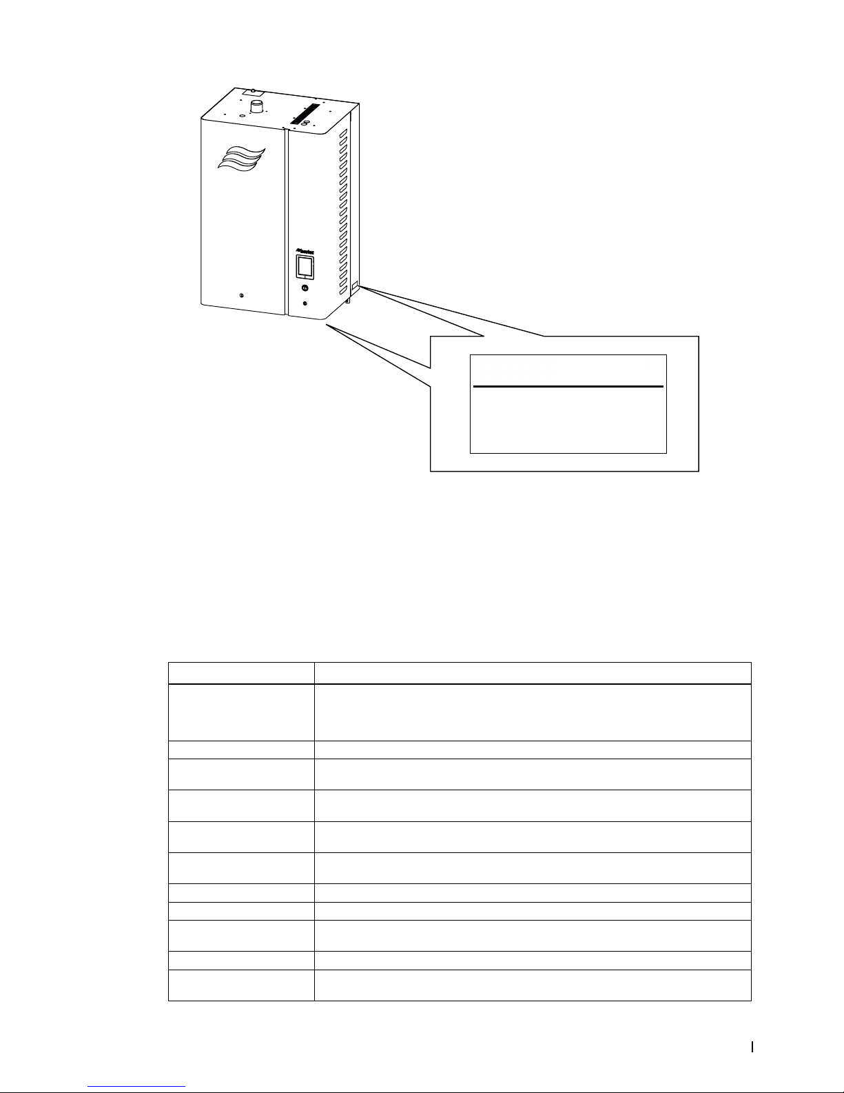
– Verify the model type on the rating label to ensure that it is suitable for your installation. Refer to
Figure 3 on page 9.
3.2 Storage and Transportation
Storage
Store the Nortec EL steam humidier in its original packaging inside a protected area that meets the
following requirements until it is installed, or if it needs to be stored for an extended period of time:
– Room temperature: 41 to 104 °F (5 to 40 °C)
– Room humidity: 10 to 75% RH
Transportation
For optimum protection always transport the unit and components in their original packaging, and use
appropriate lifting/transporting devices.
Packaging
Keep the original packaging of the unit/components for later use.
If the packaging needs to be disposed off, observe local regulations on waste disposal. Recycle packaging where possible.
Page 10

6 Receiving and Storage
2582302_C_EN_1611 Nortec EL
This page intentionally left blank
Page 11
7Product Overview
Nortec EL
2582302_C_EN_1611
4 Product Overview
4.1 General Description
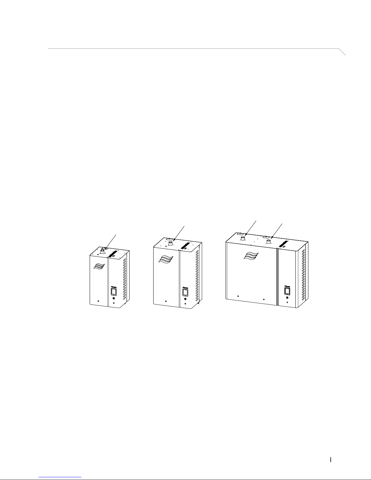
The Nortec EL steam humidier is an advanced electrode steam humidier with state-of-the-art features.
It has an integrated controller which not only controls the humidier, but also allows the humidier to be
connected to a building automation system, or an off-line computer, so it can be controlled and monitored remotely.
The Nortec EL steam humidier comes in three different housing sizes depending on the steam capacity. Refer to Figure 1. These units can range from 5 lb/h (2.2 kg/h) to 200 lb/h (91 kg/h) – refer to "Models
Overview" on page 8. Models with steam capacity up to 100 lb/h (45 kg/h) can also be ordered with a
built-on blower pack. The large models, with steam capacity from 150 lb/h (68 kg/h) to 200 lb/h (91 kg/h),
are equipped with dual steam cylinders – each with its own dedicated driver board.
The dedicated driver boards in the large models allow the steam cylinders to be congured to operate in
series, in parallel or independent mode. Two separate sets of control signals are needed for independent mode of operation. In series mode, the output capacity of steam cylinder "A" is congured to 0-50%
of humidier demand, and steam cylinder "B" to 50-100% of humidier demand. In parallel mode, the
output capacity of each steam cylinder is congured to 0-100% of humidier demand.
In addition, up to six integrated controllers (for a maximum of 12 steam cylinders) can be set up in a
"main-extension" conguration using Nortec's Linkup system to satisfy large humidication needs.
Figure 1:
1
2
3
4
Nortec EL Steam Humidier Model Sizes
1 Small model, steam cylinder "A" only
2 Medium model, steam cylinder "A" only
3 Large model, steam cylinder "B"
4 Large model, steam cylinder "A"
Page 12

8 Product Overview
2582302_C_EN_1611 Nortec EL
4.2 Models Overview
The Nortec EL steam humidier is available in different sizes (S, M and L) with different heating voltages
and steam capacities as shown in Table 1 below.
Table 1: Nortec EL Steam Humidier Models
Housing
Size
Nortec EL
Model
110-
120V/1~
208V/1~
220-
240V/1~
277V/1~
380-
415V/1~
440-
480V/1~
550-
600V/1~
208V/3~
220-
240V/3~
380V/3~
440-
480V/3~
550-
600V/3~
lb/h
(kg/h)
lb/h
(kg/h)
lb/h
(kg/h)
lb/h
(kg/h)
lb/h
(kg/h)
lb/h
(kg/h)
lb/h
(kg/h)
lb/h
(kg/h)
lb/h
(kg/h)
lb/h
(kg/h)
lb/h
(kg/h)
lb/h
(kg/h)
S 005 5
(2.2)
– – – – – – – – – – –
010 – 10
(4.5)10(4.5)10(4.5)10(4.5)10(4.5)10(4.5)
– – – – –
020 – 20
(9)
20
(9)
20
(9)
20
(9)
20
(9)
20
(9)
20
(9)
20
(9)
20
(9)
20
(9)
20
(9)
030 – – – – – – 30
(13.6)30(13.6)30(13.6)30(13.6)30(13.6)
M 050 – – – – – – 50
(22.7)50(22.7)50(22.7)50(22.7)50(22.7)
075 – – – – – – 75
(34)75(34)75(34)75(34)75(34)
100 – – – – – – 90
(41)
100
(45)
100
(45)
100
(45)
100
(45)
L 150* – – – – – – 150
(68)
150
(68)
150
(68)
150
(68)
150
(68)
200* – – – – – – 180
(82)
200
(91)
200
(91)
200
(91)
200
(91)
* These models have two steam cylinders.
4.3 Model Designation
The specication label on the side (and the underside) of the Nortec EL steam humidier shows its model
number, serial number and ratings – refer to Figure 3 on page 9. The breakdown of the model number
is shown in Figure 2. For other details of the specication label refer to the Operation and Maintenance
Manual.
Figure 2:
Nortec EL 100 400V/3~Space
Product series:
Steam capacity (lb/h):
Model:
Blank = Duct
Space = with Blower Pack
RMBP = with power for remote-mounted Blower Pack
Heating voltage and phase:
Model Breakdown
Page 13
9Product Overview
Nortec EL
2582302_C_EN_1611
Figure 3:
Circuit Protection
MADE IN CANADA
HUMIDIFIER
LISTED
205X
MODEL:
VOLTS:
AMPS:
KW:
MAX:
XXXXXXXXXXXXXXXXXXXXXXXX
S/N:
XXXXXXX
XXXXXXXXXXXX
PHASE:
XXXX
HZ:
XXXXXX
XXXXX
XXXXXXXXX
XXX
DATE:
XXXXXXXXX
XXXXXXXX B
AMPS
Nortec EL Steam Humidier Specication Label
4.4 Options
Table 2 shows the list of options for the Nortec EL steam humidier. Contact your Nortec representative
for details.
Table 2: Nortec EL Options
Option Application
Mounting bar Provides two mounting bars which t into each other for wall mounting. One bar is fastened
to the humidier, the other bar is fastened to the wall. The unit can be hung onto the wall by
engaging the two mounting bars. Note: The unit can also be wall mounted (without this option) using the keyhole cutouts on the back of the humidier housing.
Mounting rack Stand-alone rack for mounting the Nortec EL steam humidier.
Remote fault indication PCB
(printed circuit board)
Printed circuit board with relay contacts for connecting remote status displays for “Unit On”,
“Steam”, “Error” and “Service”.
Accessory relay PCB
(printed circuit board)
Printed circuit board with relay contacts for connecting other accessories such as fans and
supply water ushing valves.
Internal primary fusing Optional internal fuse for heating voltage power supply. Only available as a factory-installed
option. Note: This is not a substitute for a dedicated external disconnect switch.
Fill cup extension Kit for extending the ll cup so the humidier can accommodate backpressure of up to
10 in H20 (2.49 kPa).
Extreme drain water cooling Kit for cooling drain water to less than 120°F (49°C) before it is discharged into the drain.
Foam detection kit Kit for extending the ability of the humidier to handle a wider range of water supply quality.
BACnet MSTP BTL PCB to provide BTL certied BACnet MSTP. This option also enables full Master functionality
when using BACnet MSTP.
BACnet IP BTL PCB to provide BTL certied BACnet IP.
LonWorks board Supplementary board to connect the Nortec EL to a building management system using
LonWorks.
Page 14
10 Product Overview
2582302_C_EN_1611 Nortec EL
Option Application
Remote blower pack power
kit
When a remote blower pack is being installed with the humidier, this option provides a
transformer, fusing, and a terminal block inside the humidier to provide power to the remote
blower pack. Without this option, a separate 110-120V supply must be provided for the
remote blower pack.
4.5 Accessories
Table 3 shows the list of accessories for the Nortec EL steam humidier. Contact your Nortec representative
for details. To install and operate the accessories, refer to the instructions supplied with the accessories.
Table 3: Nortec EL Accessories
Accessory Application
Steam distributor Steam distribution system for use in an air duct.
SAM-e steam distribution
manifold
Steam distribution system for use in an air duct where reduced absorption distance is required.
Blower pack, built-on or
remote
For direct room humidication or use in conditioned spaces without a built-in air distribution
system. The EL Space model has a blower pack mounted directly, the EL RMBP model has
power for a remote-mounted blower pack (blower pack ordered as an accessory).
Digital or analog control
humidistat with either On/Off
or modulating operation
Input device used to meter the output of the humidier based on the sensed relative humidity.
The humidistat can be installed in the conditioned space that is being humidied, or within
the duct.
Digital RH transducer Input device used to communicate the relative humidity in a conditioned space or a duct to
the humidier.
Digital or analog high limit
humidistat with either On/Off
or modulating operation
Input device used to limit the output of the humidier by either shutting it down or throttling it
down when the humidity in the duct approaches the high limit.
Air proving switch Input device to ensure that humidication only occurs when air is moving through the duct.
Outdoor temperature sensor Input device used to communicate the outdoor temperature to the humidistat so that it can
lower the setpoint value during cold weather to prevent condensation on exterior windows/
surfaces.
Page 15
11Installation
Nortec EL
2582302_C_EN_1611
5 Installation
5.1 General
Strictly observe and perform all installation tasks including the mounting of the unit and connection of
the water, steam and power supplies as described in this manual.
Observe and comply with all local and national codes dealing with water, steam and electrical installations.
Nortec does not accept any liability for installation of humidication equipment by unqualied personnel,
or the use of equipment/parts that are not authorized by Nortec.
PersonnelQualications
All installation work must be performed only by licensed personnel authorized by the customer. It is the
customer’s responsibility to verify qualications of the personnel.
Safety
Observe the following safety precautions:
DANGER!
Risk of electric shock!
The Nortechumidierismainspowered.Livepartsmaybeexposedwhenthedoorpanels
are open. Touching live parts may cause severe injury or even death.
Prevention: The Nortec humidier must be connected to the mains only after all installation work
has been completed, checked for correct workmanship, and the door panels are closed and fastened securely.
CAUTION!
Risk of damage to internal components from electrostatic discharge (ESD)!
Theelectroniccomponentsinsidethehumidieraresensitivetoelectrostaticdischarge
(ESD).
Prevention: Take appropriate measures to protect the electronic components inside the unit against
damage caused by electrostatic discharge (ESD). Refer to ANSI/ESD-S20.20.
Page 16
12 Installation
2582302_C_EN_1611 Nortec EL
5.2 Installation Overview
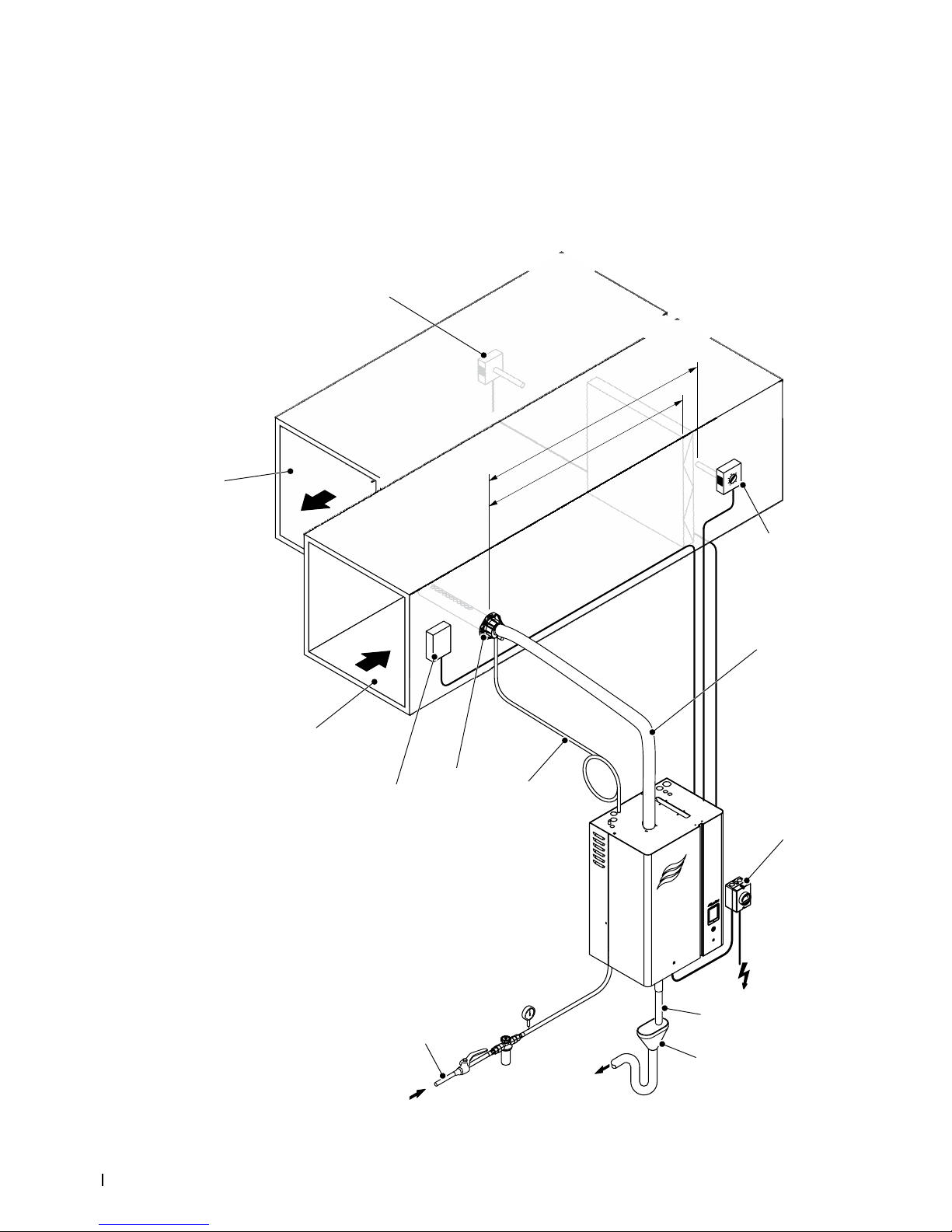
The Nortec EL humidier can use a steam distributor to distribute steam through air ducts – refer to
Figure 4. The humidier can also use a blower pack to distribute steam directly into a conditioned space
– refer to Figure 5 on page 14.
5.2.1 TypicalInstallationforDuctHumidication
Figure 4:
min. 10 ft (3m)
B or min. 8-10 ft (2.4-3m)
n
1, 2
4
5
6
7
8
9
10
12
13
2, 3
11
Typical Installation for Duct Humidication
Page 17

13Installation
Nortec EL
2582302_C_EN_1611
Legend:
1 High limit On/Off humidistat (external safety chain)
2 Humidity sensor or modulating humidistat (used for control of space in return duct, or high limit in supply duct)
3 On/Off humidistat (used for humidity control)
4 Steam line (see Note 1 below)
5 Electrical disconnect, high voltage supply
6 Drain line (see Note 2 below)
7 Air gap with optional trap (see Note 3 below)
8 Water supply (see Note 4 below)
9 Condensate line (see Note 5 below)
10 Steam distributor (see Note 6 below)
11 Air proving switch (external safety chain)
12 Supply air duct
13 Return air duct
Note1: The steam line should be as short as possible – the maximum length varies depending on unit
capacity and material used (refer to Table 6 on page 28). The steam line should have adequate upslope
(minimum 10°) /downslope (minimum 2°), without restrictions and with a condensate trap at the lowest
point. Steam traps are required every 15 ft (5 m) for long runs. The steam line must rise a minimum of
12 in (30 cm) straight up before running to the steam distributor. The minimum bend radius for steam
hose is 12 in (30 cm), or 5× the internal diameter for rigid pipes. Refer to Table 6 on page 28 for steam
line recommendations.
Note2: The drain line should have a minimum internal diameter of 7/8 in (22 mm), with a constant
minimum downslope of 1 in/48 in (1.2°) to the funnel, and must not touch the sides or bottom of funnel.
Note3: The air gap and trap should be located to the left of the humidier, as shown. A 2-1/2 in to 7/8 in
(63.5 mm to 22 mm) reducer is ideal (Nortec option P/N 2522172). The hose must not touch the bottom
of the funnel.
Note4: Water supply should be potable drinking water, with conductivity of 150-1200 micro-siemens/
cm (0-12 gpg). The water supply line should have a minimum diameter of 1/2 in (13 mm) with a shutoff
valve. An optional 5 μm lter is also recommended. Water temperature should be 34-104°F (1-40°C).
Pressure should be surge-free and regulated to 30-80 psig (207-550 kPa).
Note5: Condensate drain line from the steam distributor should have a constant minimum downslope
of 1 in/48 in (1.2°), with no restrictions and a minimum trap height of 8 in (200 mm). The trap should be
located a minimum of 12 in (30 cm) below the steam distributor.
Note6: The distance from the steam distributor to any obstruction or transition in the duct should be
equal to the calculated absorption distance B
n
or a minimum of 8-10 ft (2.4-3 m) if Bn is not known. For
details refer to the installation manual for the relevant steam distribution system. The absorption distance
can be obtained using Nortec HELP. The steam distributor capacity must equal or exceed the maximum
capacity of the humidier.
Page 18
14 Installation
2582302_C_EN_1611 Nortec EL
5.2.2 TypicalInstallationforDirectRoomHumidication
Figure 5:
1
2
3
4
5, 6
7
8
9
10
11
12
Typical Installation for Direct Room Humidication
1 Blower pack, remote-mounted
2 Steam line (see Note 1 below)
3 Blower pack, built-on
4 High level On/Off humidistat (external safety chain)
5 Humidity sensor or humidistat (used for control of space humidity or high limit)
6 On/Off humidity control
7 Electrical disconnect, high voltage supply
8 Drain line (see Note 2 below)
9 Air gap with optional trap (see Note 3 below)
10 Water supply (see Note 4 below)
11 Condensate drain line (routed to oor drain, see Note 5 below)
12 Condensate drain connection through ll cup to steam cylinder (for remote blower pack)
Note1: The steam line should be as short as possible – the maximum length varies depending on unit
capacity and material used (refer to Table 6 on page 28). The steam line should have adequate upslope
(minimum 10°) /downslope (minimum 2°), without restrictions and with a condensate trap at the lowest
point. Steam traps are required every 15 ft (5 m) for long runs. The steam line must rise a minimum of
12 in (30 cm) straight up before running to the steam distributor. The minimum bend radius for steam
hose is 12 in (30 cm), or 5× the internal diameter for rigid pipes. Refer to Table 6 on page 28 for steam
line recommendations.
Page 19

15Installation
Nortec EL
2582302_C_EN_1611
Note2: The drain line should have a minimum internal diameter of 7/8 in (22 mm), with a constant minimum downslope of 1 in/48 in (1.2°) to the funnel, and must not touch the side or bottom of the funnel.
Note3: The air gap and trap should be located to the left of the humidier, as shown. A 2-1/2 in to 7/8 in
(63.5 mm to 22 mm) reducer is ideal (Nortec option P/N 2522172). The hose must not touch the bottom
of the funnel.
Note4: Water supply should be potable drinking water, with conductivity of 150-1200 micro-siemens/
cm (0-12 gpg). The water supply line should have a minimum diameter of 1/2 in (13 mm) with a shutoff
valve. An optional 5 μm lter is also recommended. Water temperature should be 34-104°F (1-40°C).
Pressure should be surge-free and regulated to 30-80 psig (207-550 kPa).
Note5: For remote-mounted blower pack, the condensate line can be routed to either an external drain
or to the ll cup of the humidier. The condensate drain line from the blower pack should have a constant
minimum downslope of 1 in/48 in (1.2°), with no restrictions and a minimum trap height of 8 in (200 mm).
The trap should be located a minimum of 12 in (30 cm) below the condensate port on the blower pack.
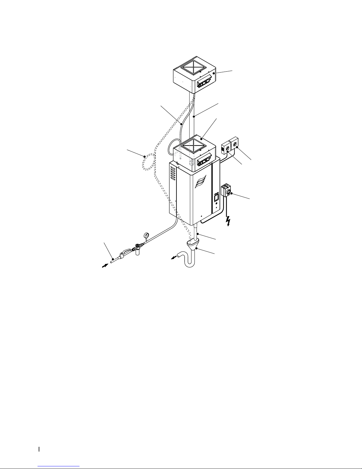
5.3 Site Requirements
In preparation for installation of the Nortec EL steam humidier, make sure that the following site requirements are satised. Report any discrepancies to the site engineer.
SteamandCondensateLines:
When choosing the location of the humidier, install it as close as possible to the steam distributor
to minimize heat loss through the steam line.
When possible, install the humidier below the steam distributor. Make sure that the selected loca-
tion permits proper routing of steam and condensate lines as described in "Best Practices for Installing
Steam and Condensate Lines" on page 26.
Mounting
Allow adequate clearances around the humidier for ease of maintenance. Although the
Nortec EL steam humidier requires no side clearance, Nortec recommends minimum clearances
of 6 in (150 mm) on the side. A 24 in (610 mm) clearance between the humidier and the ground is
required. Observe all local and national installation codes. Nortec is not responsible for any installation code violations.
Do not mount the humidier on hot surfaces, or surfaces that can freeze, or near vibrating compo-
nents, or on the oor. In addition, the mounting surface must be able to withstand temperatures of
140-158°F (60-70°C) that can be generated during operation of the humidier.
The humidier should be mounted on a wall or other suitable surface that offers a sufciently high
load-bearing capacity. Refer to Table 15 on page 59 for operating weights.
The Nortec EL steam humidier should be installed in a drip-proof location within buildings, where
the ambient temperature is 41-104°F (5-40°C) and the relative humidity is 5-95% (non-condensing).
Water Supply
The water supply to the humidier must be cold potable drinking water, and not reverse osmosis
(RO) or deionized (DI) water. The water quality requirements are listed in Table 4 below.
Table 4: Water Quality Requirements
Conductivity
(μS/cm)
Hardness
(gpg)
Silica
(ppm)
Alkalinity
(pH)
150-1200* 0-12 0-4 7-7.5
0-3 4-14
* Default humidier conguration supports approximately 330-670 μS/cm.
The water supply should have a minimum ow rate of 0.9 gpm (3.3 L/min), and should be pressure
regulated to 30-80 psig (207-550 kPa), with spike pressure limited to 120 psig (827 kPa).
The water supply should be ltered to 5 μm (optional, but recommended).
Page 20

16 Installation
2582302_C_EN_1611 Nortec EL
Water temperature should be 34-104°F (1-40°C).
The diameter of the water supply piping should be minimum 1/2 in (13 mm), and must have a 1/2 in
NPT female end.
The water supply line should be made of copper, stainless steel or plastic certied for drinking water
systems.
A shutoff valve and a union tting must be supplied in the water supply line for ease of maintenance.
The water supply should be free of additives such as corrosion inhibitors, disinfectants, etc., which
may affect the performance of the humidier. If using softened or partially softened water, contact
your Nortec representative for assistance.
Drainage
The humidier should be connected to a dedicated building drain (recommended) with a minimum
drainage rate of 2.3 gal/min (8.7 L/min) per steam cylinder. For safety reasons, drain water from the
humidier should not empty into a sink used by personnel. The drain line must allow free and easy
draining. A restricted drain can cause water in the humidier to over-concentrate and result in poor
operation, or cause water to back up at the air gap funnel.
The building drain pipe should be made of either copper or stainless steel (minimum DIN 1.4301)
so it can handle drain water temperatures up to 212 °F (100 °C).
The space in which the humidier is to be installed should have a oor drain. However, if a oor drain
is not available, a leakage monitoring device must be installed (by others) to permit interruption of
the water supply in case of a leakage.
Power Supply
The power supply to the humidier should be adequate to match the full voltage and current draw
shown on the specication label of the humidier.
The power supply must have an external dedicated fused disconnect switch. The fusing must not
exceed the maximum circuit protection indicated on the specication label. Refer to Figure 3 on page 9.
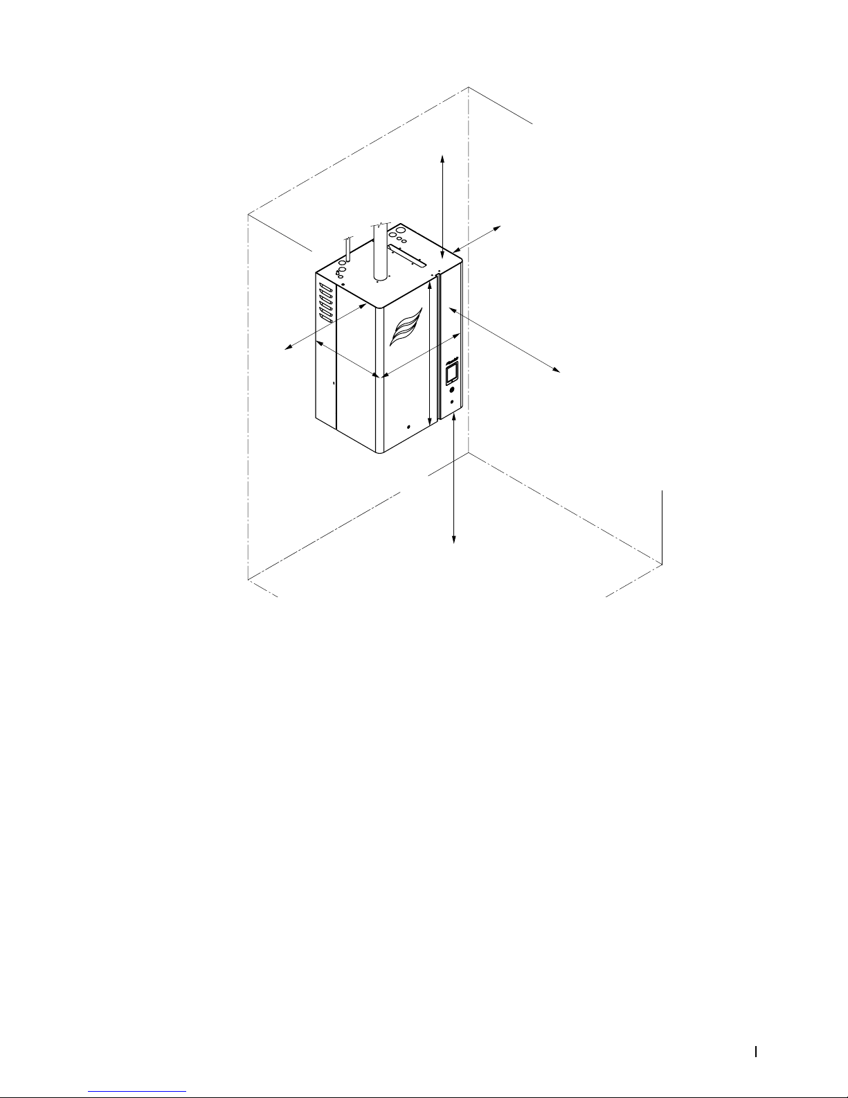
5.4 MountingtheHumidier
Refer to "Site Requirements" on page 15 for the location and mounting requirements for the
Nortec EL steam humidier.
5.4.1 Location and Clearances
The location of the humidier depends largely on the steam distribution system. For the required minimum
clearances for a Nortec EL steam humidier with a built-on blower pack refer to "Placement of Humidier" on
page 24; or refer to the blower pack manual for a remote-mounted blower pack.
For all other steam distribution systems refer to Figure 6. The clearance dimensions shown are for reference only, and are suggested clearances for ease of maintenance. Consult local and national installation
codes. Nortec does not accept responsibility for violations of the installation codes.
Page 21
17Installation
Nortec EL
2582302_C_EN_1611
Figure 6:
W
D
H
0 in
(0 mm)
min. 24 in
(610 mm)
min. 12 in
(300 mm)
min. 36 in
(915 mm)
0 in
(0 mm)
Nortec EL Humidier Suggested Clearances
Page 22

18 Installation
2582302_C_EN_1611 Nortec EL
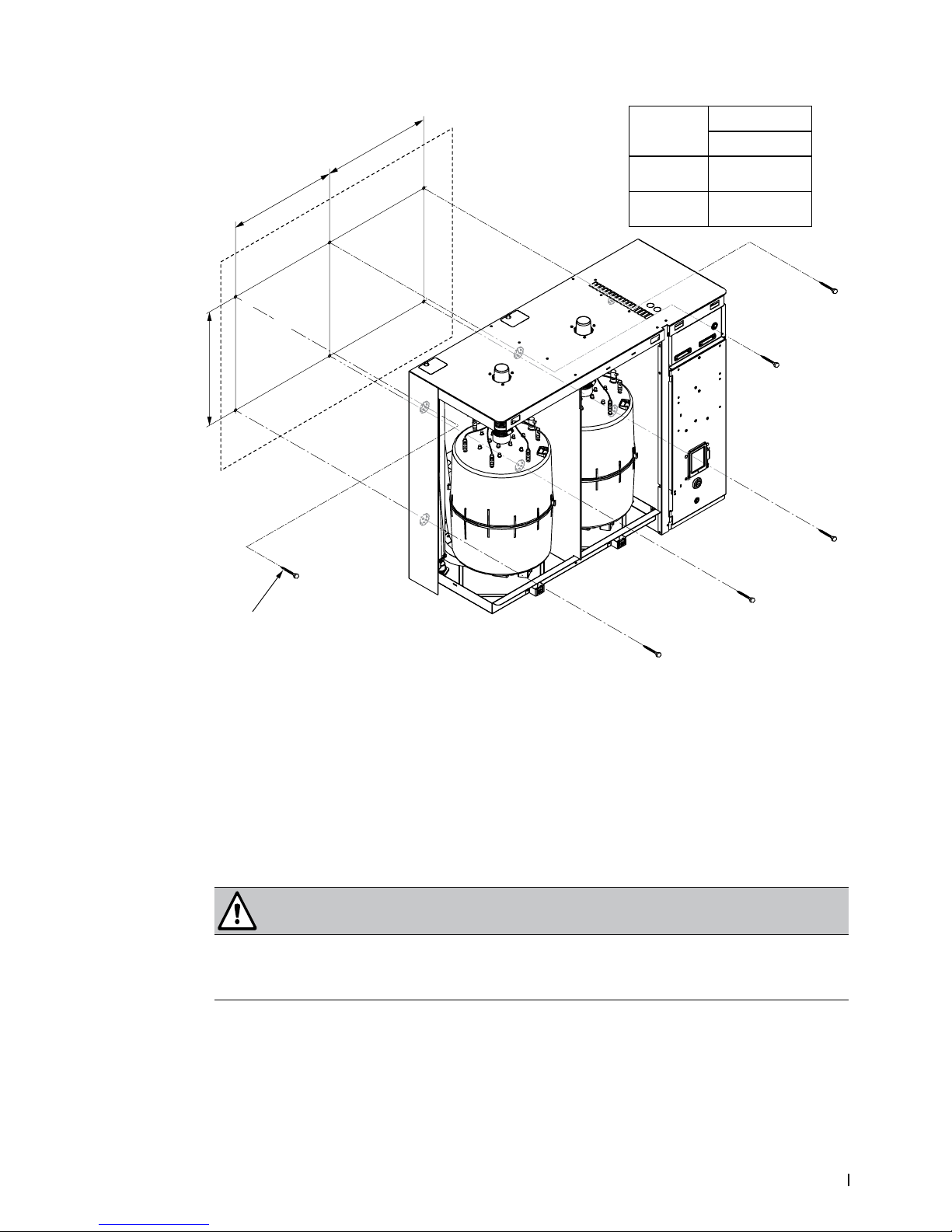
5.4.2 Standard Mounting
Locate the Nortec EL humidier according to "Location and Clearances" on page 16, and install it on the
mounting surface as follows:
1. Locate 2×4 wooden studs or equivalent support in the mounting surface, and mark the attachment
points “A” and “B” at the desired position with the help of a level. For small or medium housing refer
to Figure 7. For large housing refer to Figure 8 on page 19.
Figure 7:
A
A
B
B
X
Y
1
Standard Mounting, Small or Medium Housing
1 Lag bolt, 1/4×2 in (×4)
Dimension
Housing Size
Small Medium
X 12.0 in
(305 mm)
16.0 in
(406 mm)
Y 17.56 in
(446 mm)
20.71 in
(526 mm)
Page 23
19Installation
Nortec EL
2582302_C_EN_1611
Figure 8:
X
A
A
A
B
B
B
X
Y
1
Standard Mounting, Large Housing
1 Lag bolt, 1/4×2 in (×6)
2. Install 1/4×2 in lag bolts (supplied by others) at attachment points "A". Use longer screws if going
through drywall or other structural material into the mounting surface. Allow the heads of the screws to
extend 0.25 in (5 mm) from the mounting surface so that the humidier can be installed on the bolts.
3. Remove the door panels from the humidier.
WARNING!
Heavy object – risk of injury!
Thesmallhumidierweighs45lb(20kg),andthelargehumidierweights120lb(54kg).
Prevention: Use an appropriate lifting device, or request assistance to raise the humidier into
position.
4. Carefully raise and install the humidier onto the installed lag bolts.
5. Align the humidier with the help of a level, then tighten the lag bolts.
6. Install additional lag bolts (supplied by others) into the mounting surface at attachment points “B”,
and fasten securely.
7. Reinstall the door panels, and fasten them securely.
Dimension
Housing Size
Large
X 16.0 in
(406 mm)
Y 16.75 in
(426 mm)
Page 24
20 Installation
2582302_C_EN_1611 Nortec EL
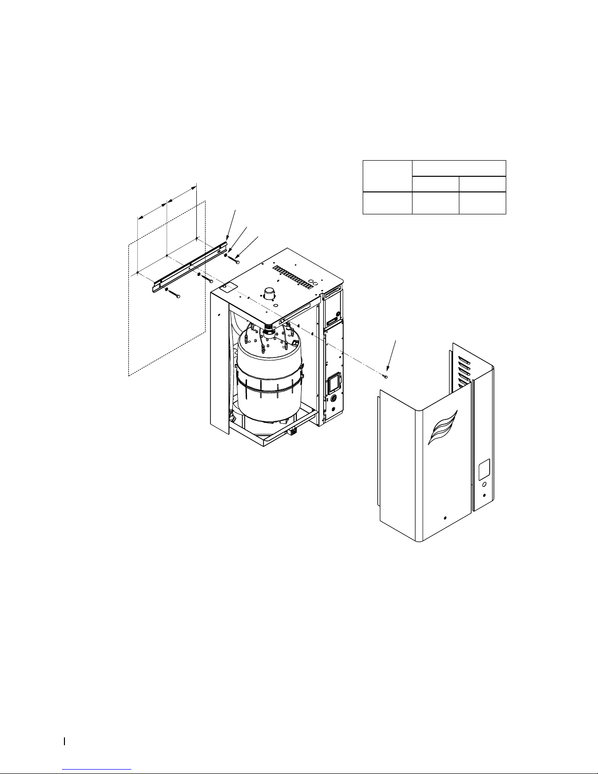
5.4.3 Mounting Using Optional Mounting Bar
Locate the Nortec EL humidier according to "Location and Clearances" on page 16, and install it on the
mounting surface as follows using the optional mounting bar. Mounting bars are a factory-installed option.
If ordered, the corresponding bars and bumpers will be riveted/installed to the housing at the factory.
1. Locate 2×4 wooden studs or equivalent support in the mounting surface, and mark the attachment
points “A” at the desired position with the help of a level. For small or medium housing refer to Figure 9.
For large housing refer to Figure 10 on page 21.
Figure 9:
X
A
A
A
X
1
2
3
4
Optional Mounting, Small or Medium Housing
1 Mounting bar
2 Flat washer (×3)
3 Lag bolt, 1/4×2 in (×3)
4 Screw, M6×10 (×1), supplied
Dimension
Housing Size
Small Medium
X 6.0 in
(152 mm)
8.0 in
(203 mm)
Page 25

21Installation
Nortec EL
2582302_C_EN_1611
Figure 10:
X
A
X
A
A
1
2
3
4
Optional Mounting, Large Housing
1 Mounting bar
2 Flat washer (×3)
3 Lag bolt, 1/4×2 in (×3)
4 Screw, M6×10 (×1), supplied
2. Align the holes in the mounting bar with the marks for the attachment points "A", and install the
mounting bar on the mounting surface with 1/4×2 in lag bolts and at washers (supplied by others).
Use longer bolts if going through drywall or other structural material into the mounting surface. Level
the mounting bar before tightening the lag bolts.
3. Remove the door panels from the humidier.
WARNING!
Heavy object – risk of injury!
Thesmallhumidierweighs45lb(20kg),andthelargehumidierweights120lb(54kg).
Prevention: Use an appropriate lifting device, or request assistance to raise the humidier into
position.
4. Carefully raise the humidier into position, and hang it on the mounting bar.
5. Secure the humidier to the mounting bar with the M6×10 screw (supplied), and fasten securely.
6. Reinstall the door panels, and fasten them securely.
Dimension
Housing Size
Large
X 16.0 in
(406 mm)
Page 26

22 Installation
2582302_C_EN_1611 Nortec EL
5.4.4 Mounting to OSHPD Seismic Requirements
The Nortec EL is certied to OSHPD seismic requirements in its standard conguration (reference OSP0225-10); no additional kits are required. The humidier must be mounted as per the instructions in this
section in order to fulll the seismic requirements.
Locate the Nortec EL humidier according to "Location and Clearances" on page 16, and secure it to doublelayered 3/4 in (20 mm) thick plywood (or equivalent) as follows:
1. Secure the double-layered 3/4 in (20 mm) plywood sheets to the selected mounting surface.
2. Mark the attachment points “A” and "B" at the desired position on the plywood sheets (or equivalent)
with the help of a level. For small or medium housing refer to Figure 11. For large housing refer to
Figure 12 on page 23.
3. Install 3/8×2 in grade B5 (or equivalent) lag bolts and at washers (supplied by others) at attachment
points "A". Allow the heads of the screws to extend 0.25 in (5 mm) from the mounting surface so that
the humidier can be installed on the bolts.
Figure 11:
A
A
B
B
X
Y
2
3
1
Optional Seismic Mounting, Small or Medium Housing
1 Lag bolt, 3/8×2 in, grade B5 (×4)
2 Flat washer (×4)
3 3/4 in (20 mm) double-layer plywood sheet (or equivalent)
Dimension
Housing Size
Small Medium
X 12.0 in
(305 mm)
16.0 in
(406 mm)
Y 17.56 in
(446 mm)
20.71 in
(526 mm)
Page 27

23Installation
Nortec EL
2582302_C_EN_1611
Figure 12:
X
A
A
A
B
B
B
X
Y
1
2
3
Optional Seismic Mounting, Large Housing
1 Lag bolt, 3/8×2 in, grade B5 (×6)
2 Flat washer (×6)
3 3/4 in (20 mm) double-layer plywood sheet (or equivalent)
4. Remove the door panels from the humidier.
5. Enlarge the mounting holes in the rear of the cabinet to accommodate the 3/8×2 in lag bolts.
WARNING!
Heavy object – risk of injury!
Thesmallhumidierweighs45lb(20kg),andthelargehumidierweights120lb(54kg).
Prevention: Use an appropriate lifting device, or request assistance to raise the humidier into
position.
6. Carefully raise and install the humidier onto the installed lag bolts.
7. Align the humidier with the help of a level, then tighten the lag bolts.
8. Install additional grade B5 (or equivalent) lag bolts and at washers (supplied by others) into the
plywood sheet (or equivalent) at attachment points “B”, and fasten securely.
9. Reinstall the door panels, and fasten them securely.
Dimension
Housing Size
Large
X 16.0 in
(406 mm)
Y 16.75 in
(426 mm)
Page 28

24 Installation
2582302_C_EN_1611 Nortec EL
5.4.5 Mounting Checklist
Check the following to ensure that the humidier has been mounted correctly:
Unit installed in the correct location (according to "Location and Clearances" on page 16)?
Mounting surface stable, and capable of supporting the full operating weight of the humidier?
Unit level?
Unit fastened securely?
5.5 Steam Line Connections
Steam generated by the Nortec EL humidier is not pressurized, but is delivered at atmospheric pressure.
It can be distributed directly into a conditioned space with a built-on or remote-mounted blower pack, or into
an AHU (air handling unit) using Nortec steam distributors or Nortec SAM-e steam distribution manifold.
Read "Best Practices for Installing Steam and Condensate Lines" on page 26 before installing steam lines.
5.5.1 Steam Distribution Using the Air Handling Unit
For placement of the steam distributor or SAM-e steam distribution manifold in the air handling unit, as
well as best practices and installation procedures, refer to their installation manuals.
5.5.2 Steam Distribution Using the Blower Pack
5.5.2.1 PlacementofHumidier
Figure 13 on page 25 and Table 5 show the minimum clearances required for installation of a
Nortec EL steam humidier with a built-on Nortec blower pack.
Table 5: Minimum Clearances
Blower Pack
Capacity
5 lb/h
(2.3 kg/h)
10 lb/h
(4.5 kg/h)
20 lb/h
(9kg/h)
30 lb/h
(13.6 kg/h)
50 lb/h
(22.7 kg/h)
75 lb/h
(34.0 kg/h)
100 lb/h
(45.4 kg/h)
Low Speed
Dimension "A" (minimum), Low speed 9 in
(0.23 m)
18 in
(0.46 m)
75 in
(1.91 m)
86 in
(2.19 m)
174 in
(4.42 m)
189 in
(4.81 m)
248 in
(6.3 m)
Dimension "B" (minimum), Low speed 12 in
(0.31 m)
48 in
(1.22 m)
84 in
(2.14 m)
High Speed
Dimension "A" (minimum), High speed 6 in
(0.16 m)
60 in
(1.53 m)
71 in
(1.81 m)
132 in
(3.36 in)
153 in
(3.89 m)
218 in
(5.54 m)
Dimension "B" (minimum), High speed 12 in
(0.31 m)
Dimension "C" (minimum) 90 in
(2.3 m)
Dimension "D" (suggested) 12 in
(0.31 m)
30 in
(0.77 m)
Note:
The values in Table 5 are based on the following nominal conditions: 72°F (22˚C), 40% RH.
Blower pack should not be installed near cold surfaces or where dew point may be reached.
Higher humidity or lower room temperature (compared to nominal conditions stated above) will require increased clearances.
Page 29

25Installation
Nortec EL
2582302_C_EN_1611
Figure 13: Clearance Requirements for
B
C
D
D
A
Nortec EL Humidier with Built-on Blower Pack
5.5.2.2 Remote-MountedBlowerPack
For the installation requirements and installation procedure for the remote-mounted blower pack, refer
to the blower pack manual.
Page 30

26 Installation
2582302_C_EN_1611 Nortec EL
5.5.3 Best Practices for Installing Steam and Condensate Lines
Nortec recommends that you observe the following best practices for installing atmospheric steam lines
and condensate lines. Refer to Figure 16, Figure 17, Figure 18 and Figure 19 for installation examples.
Steam Lines
– Use rigid steam pipes made of copper (MED Type-L) or stainless steel (minimum DIN 1.4301) ex-
clusively, and use steam hoses for short distances only. Use original steam and condensate hoses
from your local Nortec representative. Steam and condensate lines made of any other materials
may adversely affect the operation of the unit, and will void the warranty. Refer to Table 6 on page 28
for details.
WARNING!
Excessive backpressure can result in serious injury or damage to equipment!
Excessive backpressure in the steam line may affect the proper functioning of the humidier,
and may also cause unexpected release of hot steam vapors. Bare skin exposed to the hot
steam vapours can result in severe burns.
Prevention: Minimize the length of the steam line and the number of bends, as the backpressure
can rise approximately 0.12 in H2O for every foot (100 Pa for every meter) of steam line, and
every 90° elbow.
– The length of the steam line should be kept as short as possible – refer to Table 6 on page 28 for
details. Avoid 90° bends, or use long radius elbows. Minimum bend radius is 12 in (300 mm) for
steam hoses, and 5× the internal diameter for rigid steam pipes. Exceeding the maximum length
can affect performance of the unit and may void the warranty. Backpressure in the line combined
with duct static pressure must not exceed 5.5 in H2O (1.37 kPa) and 10 in H2O (2.49 kPa) with the
optional ll cup extension.
Note: With oversized steam lines the maximum length can be extended. Use Nortec steam hose
for short distances only. When calculating the total equivalent length, refer also to Table 7 on page 28
for equivalent length of common ttings.
IMPORTANT! When determining the length and routing of steam lines, allowances must be
made for thermal expansion. If a steam hose is used, allowances must be made for shrinkage
in the length of the hose due to aging.
– Do not decrease the diameter of the steam line, as it increases the backpressure in the line and
also allows condensation of the steam. If that is unavoidable, install a Nortec steam line reducer at
the connection to the steam distributor only, and install a condensate line just before the restriction.
Contact your local Nortec representative for details of the reducer.
– If necessary, increase the diameter of the steam line on the downslope and install a condensate
trap at the lowest point.
– Do not combine steam lines except at the steam distributor. Use a Nortec adaptor specically de-
signed for that purpose, and only if the humidier steam cylinders operate in parallel.
– If using blower packs with large Nortec EL humidiers, do not connect the output from both steam
cylinder to a single blower pack. Each blower pack has a maximum capacity of 100 lb/h (45 kg/h).
– The steam line from the humidier must lead straight upwards for a minimum of 12 in (300 mm)
before continuing on to the steam distribution system.
– The steam line must have a constant minimum upslope of 2 in/12 in (10°), or a constant minimum
downslope of 1/2 in/12 in (2°), as shown in Figure 14 on page 27.
– Use short lengths of steam hose to connect the steam line to the humidier or steam distributor.
Secure the steam hoses with clamps.
Page 31

27Installation
Nortec EL
2582302_C_EN_1611
CAUTION!
Do not over-tighten the hose clamp on the steam hose. Maximum torque for 7/8 in (22 mm)
clamps is 12 in·lbs (135 N·cm), and 16 in·lbs (180 N·cm) for 1-3/4 in (45 mm) clamps.
Figure 14:
10
o
2
o
12 in
(300 mm)
2 in
(50 mm)
12 in
(300 mm)
½ in
(12 mm)
Minimum Upslope Minimum Downslope
Steam Line Slope
– To minimize formation of condensation and maximize efciency, the steam lines made of rigid pipes
(copper or stainless steel) must be insulated with a minimum of 1 in (25 mm) of pipe insulation over
its entire length.
– The weight of the steam line must be supported so there is no load on the humidier.
WARNING!
Risk of severe burns from exposure to hot steam vapours!
Restrictions in the cross-section of the steam line will cause excessive backpressure in the
steam cylinder when the unit is operating, which may cause unexpected release of hot steam
vapors. Bare skin exposed to the hot steam vapours can result in severe burns.
Prevention: Observe the following:
• Upon completion of the installation, purge the steam line to remove any contaminants and
installation materials.
• If using a steam hose make sure there are no kinks in the hose. A heated hose is more likely
to kink.
• To prevent condensate pockets, the steam line must not sag. If necessary, support the steam
line with pipe clamps, trough, or wall brackets, and install a condensate drain at the lowest
point in the steam line.
• Do not install a shutoff valve (e.g. a manually operated shutoff valve, solenoid valve, etc.) in
the steam line.
Page 32

28 Installation
2582302_C_EN_1611 Nortec EL
Table 6: Steam Line Recommendations
Model
Steam Line Over-sizedSteamLine**
Steam
Losses***
Maximum
Equivalent
Length
MED-L
Copper
Pipe
Diameter
Stainless Steel
(min. DIN 1.4301)
Pipe Diameter
Maximum
Equivalent
Length
MED-L
Copper
Pipe
Diameter
Stainless Steel
(min DIN 1.4301)
Pipe Diameter
EL005 7 ft
(2 m)
3/4 in
(20 mm)
7/8 in
× 0.049 wall
(22 mm
× 1.25 mm wall)
14 ft
(4 m)
1 in
(25 mm)
1-1/8 in
× 0.049 wall
(29 mm
× 1.25 mm wall)
0.06 lb/h/ft
(0.09 kg/h/m)
EL010 12 ft
(3.5 m)
24 ft
(7 m)
EL020 17 ft
(5 m)
34 ft
(10 m)
EL030 22 ft
(6.5 m)
44 ft
(13 m)
EL050 43 ft
(13 m)
1-1/2 in
(40 mm)
1-3/4 in
× 0.065 wall
(45 mm
× 1.65 mm
wall)
86 ft
(26 m)
2 in
(50 mm)
2 in
× 0.065 wall
(50 mm
× 1.65 mm
wall)
0.11 lb/h/ft
(0.18 kg/h/m)
EL075
EL100
47 ft
(14 m)
94 ft
(28 m)
EL150*
EL200*
50 ft
(15 m)
1-1/2 in
(40 mm)
1-3/4 in
× 0.065 wall
(45 mm
× 1.65 mm wall)
100 ft
(30 m)
2 in
(50 mm)
2 in
× 0.065 wall
(50 mm
× 1.65 mm
wall)
Nortec Steam Hose
EL005-
EL030
10 ft
(3 m)
P/N 1328810 – 7/8 in (22 mm) 0.1 lb/h/ft
(0.15 kg/h/m)
EL050-
EL200
10 ft
(3 m)
P/N 1328820 – 1-3/4 in (45 mm) 0.15 lb/h/ft
(0.22 kg/h/m)
Notes:
* Use a single steam line for each steam cylinder. Do not combine lines except at a distributor, and only if using the humidiers in parallel.
** The over-sized lines may require a reducer at the humidier and the steam distributor.
*** Based on 1 in (25 mm) insulated copper pipe.
Table 7: Approximate Equivalent Length of Atmospheric Steam Line Fittings
Nominal
Tube Size
in (mm)
Standard90°
Elbow
ft (m)
45°Elbow
ft (m)
Side-outlet
Tee
ft (m)
0.75-0.875
(19-22)
2 (0.6) 1 (0.3) 4 (1.2)
1.5-1.75
(38-45)
3.5 (1.1) 1.75 (0.5) 7 (2.1)
3 (76) 5 (1.5) 2.5 (0.8) 11 (3.4)
4 (102) 8 (2.4) 4 (1.2) 15 (4.6)
Page 33

29Installation
Nortec EL
2582302_C_EN_1611
Condensate Lines
– The condensate drain line from the steam distributor must have a constant minimum downslope of
1 in/48 in (1.2°), with a minimum trap height of 8 in (200 mm), and may be connected to the ll cup
port on the top of the humidier, or to the building oor drain with condensate cooler as required. The
condensate trap must be at least 12 in (300 mm) below the condensate port on the steam distribution system or the "T" connector in the steam line. Refer to Figure 15.
Figure 15:
10
o
2
o
12 in
(300 mm)
2 in
(50 mm)
12 in
(300 mm)
½ in
(12 mm)
Minimum Upslope Minimum Downslope
Condensate Drain Lines
WARNING!
Riskofsevereburnsfromhotuidsorsteam!
The condensate lines may be lled with hot uids or steam. Bare skin in contact with hot uids
or steam can result in severe burns.
Prevention: Never plumb the condensate lines to empty into a sink used by personnel. Always
connect the lines to a drain according to applicable national and local plumbing codes.
– Condensate lines must also be installed at all low points and at vertical transitions in the steam
line. The condensate drain lines should always connect to full-size "T" connectors in the steam line.
Install full-size "T" connectors for condensate drain lines at all transitions from vertical to horizontal.
– For a steam line that is longer than 15 ft (4.5 m) up to the maximum recommended length, install
condensate lines and traps at regular intervals. The maximum distance between the condensate
traps for long runs is 15 ft (4.5 m).
– Use 3/8 in (9.5 mm) Nortec condensate hose, or 3/8 in (9.5 mm) stainless steel pipe or 1/4 in (6.5 mm)
copper pipe for traps in the condensate lines.
– Make sure that the condensate lines allow proper ow.
– Do not over-tighten the hose clamps on the condensate lines.
IMPORTANT! Before starting up the unit, prime the traps in the condensate lines with water.
Page 34

30 Installation
2582302_C_EN_1611 Nortec EL
Figure 16:
A
B
C
D
Installation Example – Steam Distributor 20 in (500 mm) Above Humidier
A Steam line must run minimum 12 in (300 mm) vertically before continuing on to the steam distributor.
B All condensate traps must be minimum 12 in (300 mm) below the condensate outlet on the steam distributor, and condensate lines
must have a constant minimum downslope of 1 in/48 in (1.2°).
C The steam line must not exceed the length specied in Table 6 on page 28. The minimum bend radius is 12 in (300 mm) for a steam
hose, or 5× the internal diameter for rigid steam pipes.
D All condensate traps must have a minimum height of 8 in (200 mm).
Page 35

31Installation
Nortec EL
2582302_C_EN_1611
Figure 17:
B
D
D
C
F
A
A
B
B
C
D
C
E
Installation Example – Steam Distributor Less Than 20 in (500 mm) Above Humidier
A Steam line must run minimum 12 in (300 mm) vertically before continuing on to the steam distributor.
B All condensate traps must be minimum 12 in (300 mm) below the condensate outlet on the steam distributor or the steam line.
C The steam line must not exceed the length specied in Table 6 on page 28. The minimum bend radius is 12 in (300 mm) for a steam
hose, or 5× the internal diameter for rigid steam pipes.
D All condensate traps must have a minimum height of 8 in (200 mm).
E Obstacle
F Condensate line must connect into a full-size "T" connector installed at the lowest point in the steam line.
Page 36

32 Installation
2582302_C_EN_1611 Nortec EL
Figure 18:
B
D
C
A
E
Installation Example – Rigid Steam Pipe With Insulation
A Steam line must run minimum 12 in (300 mm) vertically before continuing on to the steam distributor.
B All condensate traps must be minimum 12 in (300 mm) below the condensate outlet on the steam distributor, and condensate lines
must have a constant minimum downslope of 1 in/48 in (1.2°).
C The steam line must not exceed the length specied in Table 6 on page 28. The minimum bend radius is 12 in (300 mm) for a steam
hose, or 5× the internal diameter for rigid steam pipes.
D All condensate traps must have a minimum height of 8 in (200 mm).
E Steam line must have a minimum of 1 in (25 mm) of pipe insulation over its entire length.
Page 37

33Installation
Nortec EL
2582302_C_EN_1611
Figure 19:
A
A
B
C
E
D
Installation Example – Remote-Mounted Blower Pack
A Steam line must run minimum 12 in (300 mm) vertically before continuing on to the blower pack.
B All condensate traps must be minimum 12 in (300 mm) below the condensate outlet on the blower pack.
C The steam line must not exceed the length specied in Table 6 on page 28. The minimum bend radius is 12 in (300 mm) for a steam
hose, or 5× the internal diameter for rigid steam pipes.
D All condensate traps must have a minimum height of 8 in (200 mm).
E Steam line must have upslope (minimum 10°) /downslope (minimum 2°), and condensate line must constant minimum downslope of
1 in/48 in (1.2°).
Page 38

34 Installation
2582302_C_EN_1611 Nortec EL
5.5.3.1 Common Steam and Condensate Line Installation Mistakes
Some common steam and condensate line installation mistakes are shown in Figure 20.
Figure 20:
7
1
2, 3
4
5
4, 6
7
2, 3
2
Common Steam and Condensate Line Installation Mistakes
1 The condensate trap is located less than the required minimum 12 in (300 mm) below the steam distributor.
2 The minimum bend radius of 12 in (300 mm) for the steam hose (or 5× the internal diameter for rigid pipes) is not maintained.
3 No condensate trap is installed at the vertical transition.
4 The minimum slope for steam and condensate lines is not maintained.
5 The steam line does not run straight up for the required minimum 12 in (300 mm) before continuing on to the steam distributor.
6 On long steam line runs, condensate traps are required every 15 ft (4.5 m), and must connect into full-size "T" connectors in the steam
line. A condensate trap must also be installed a minimum of 12 in (300 mm) below the steam line.
7 Steam lines must not merge or reduce in diameter except at the steam distributor (only through a Nortec adaptor), and must have a
condensate line just before the restriction.
Page 39

35Installation
Nortec EL
2582302_C_EN_1611
5.5.4 Steam Connections Checklist
Check the following to ensure that the steam connections for the humidier have been installed correctly:
Steam Line
Observed all best practices?
Steam line exceed maximum length specied in Table 6 on page 28?
Minimum bend radius of 12 in (300 mm) for steam hose, or 5× internal diameter for rigid pipes
maintained?
Steam line sized correctly?
Backpressure in the line combined with duct static pressure exceed 5.5 in H2O (1.37 kPa), or
10 in H2O (2.49 kPa) with the optional Fill Cup Extension?
Steam lines run straight up from the humidier steam outlet for at least 12 in (300 mm) before bend?
Steam line have a constant minimum upslope of 2 in/12 in (10°), or a constant minimum downslope
of 1/2 in/12 in (2°)?
Steam lines do not reduce in diameter except, if required, at the steam distributor, and condensate
line installed just before the restriction?
Steam lines do not merge except at the steam distributor through a Nortec adaptor?
Steam line does not sag or kink? Supported adequately? Any low points in line without condensate
trap?
If a steam hose is used, is it attached securely with clamps? Clamps secure without crushing steam
line?
Allowances for thermal expansion during operation, and shortening of the hose due to aging taken
into consideration?
Condensate Line
Local codes on drain water temperature requirements have been satised?
Condensate line from the steam distributor condensate port connected to the humidier ll cup port,
or the drain?
Condensate lines installed at all low points, and at vertical transitions in the steam line?
Condensate lines in the steam line always connect to full-size "T" connectors?
Condensate traps have a minimum loop height of 8 in (200 mm) and installed at least 12 in (300 mm)
below the "T" connector or steam distributor?
All condensate lines have a constant minimum downslope of 1 in/48 in (1.2°)?
Maximum distance between the condensate traps on long runs is 15 ft (4.5 m)?
Condensate traps primed with water?
Page 40

36 Installation
2582302_C_EN_1611 Nortec EL
5.6 Water Connections
Refer to "Site Requirements" on page 15 for the water supply and drain requirements.
Read "Water Connection Requirements" on page 38, and perform the water connections as shown in Figure 21
on page 36 and Figure 22 on page 37.
5.6.1 Water Connections Overview
Figure 21:
8
10
11
5
7
6
4
2
1
3
5
4
9
Water Supply and Drain Connections, Small and Medium Units
1 Drain canal (outlet un-threaded), 1-3/16 in (30 mm) O.D.
2 Hose clamp (supplied)
3 Flexible bent hose (supplied)
4 Drain line, minimum 7/8 in (22 mm) I.D. (not supplied)
5 Water supply line, minimum 1/2 in (13 mm) (not supplied)
6 Adaptor, 3/4 BSPP to 1/2 in NPT (supplied)
7 Fill valve (3/4 in BSPP plastic threads)
8 Air gap and optional trap (not supplied)
9 Shutoff valve (not supplied)
10 Filter, 5 μm (optional, but recommended)
11 Union tting (not supplied)
Page 41

37Installation
Nortec EL
2582302_C_EN_1611
Figure 22:
1
8
5
9
10
11
5
7
6
4
2
1
3
4
Water Supply and Drain Connections, Large Units
1 Drain canal (outlet un-threaded), 1-3/16 in (30 mm) O.D.
2 Hose clamp (supplied)
3 Flexible bent hose (supplied)
4 Drain line, minimum 7/8 in (22 mm) I.D. (not supplied)
5 Water supply line, minimum 1/2 in (13 mm) (not supplied)
6 Adaptor, 3/4 BSPP to 1/2 in NPT (supplied)
7 Fill valve (3/4 in BSPP plastic threads)
8 Air gap and optional trap (not supplied)
9 Shutoff valve (not supplied)
10 Filter, 5 μm (optional, but recommended)
11 Union tting (not supplied)
Page 42

38 Installation
2582302_C_EN_1611 Nortec EL
5.6.2 Water Connection Requirements
Water and drain connections must meet the following requirements:
– All water supply and drain connections are to be installed to local plumbing codes.
– For ease of maintenance, a water shutoff valve and union tting must be installed in the supply line
before the humidier.
– The water supply piping should have a minimum diameter of 1/2 in (13 mm), with a 1/2 in NPT female
end. The piping material should be made of copper, stainless steel or plastic certied for drinking
water systems.
CAUTION!
Risk of damage to the plastic threads!
Thethreadsonthellvalvearemadeofplastic.
Prevention: Hand-tighten the NPT adaptor to the ll valve.
– The (optional but recommended) water lter must be installed as close as possible to the humidier.
– The air gap funnel should have a minimum diameter of 2-1/2 in (64 mm).
– The air gap and optional trap should be located away from the control cabinet to keep any rising
steam from damaging the electrical components in the cabinet.
– The drain piping should have a minimum internal diameter of 7/8 in (22 mm).
– The exible bent hose exiting the humidier should be connected to a drain line with a minimum
internal diameter of 7/8 in (22 mm) and secured with clamps.
– The drain line should be as short as possible, and have a constant minimum downslope of 1 in/48 in
(1.2°) to the funnel without touching its sides or bottom. Use stainless steel or copper pipe to handle
temperatures up to 212°F (100°C).
– Drain lines from large humidiers with dual steam cylinders must empty into separate open air gap
funnels before connecting to the drain. Combined drain line minimum 1.5 in (38 mm) ID.
– Upon completion of installation, ush the water supply and drain lines to clear out any debris in the
lines. Check the strainer in the ll valve to ensure it is clear of all debris.
5.6.3 Water Connections Checklist
Check the following to ensure that the water connections for the humidier have been installed correctly:
Shutoff valve and union tting installed in supply line?
Water supply piping minimum 1/2 in (13 mm) diameter, and made of copper, stainless steel or plastic
certied for drinking water systems?
Optional 5 μm water lter installed in the supply line close to the humidier?
Water supply temperature 34-104°F (1-40°C)?
Water supply surge-free and pressure regulated to 30-80 psig (207-550 kPa)?
Leak-free water supply line?
Air gap funnel has a minimum diameter of 2-1/2 in (64 mm)?
Air gap funnel and any other drain located away from the control cabinet in the humidier?
Drain lines have a minimum internal diameter of 7/8 in (22 mm)?
Drain line have a constant minimum downslope of 1 in/48 in (1.2°) to funnel without touching its
sides or bottom?
Drain lines from large humidiers with dual steam cylinders empty into separate open air gap funnels
before connecting to the drain? Combined drain line minimum 1.5 in (38 mm) ID?
All debris ushed from supply and drain lines?
Page 43

39Installation
Nortec EL
2582302_C_EN_1611
5.7 Humidity Control Systems
5.7.1 Control Device Locations
The following schematic describes a potential system setup with respect to control devices. Refer to
Figure 23.
Figure 23:
φ
φ
max
φ
Δp
1
1
2
3
System Setup Schematic
1 On/Off humidistat, modulating humidistat, or humidity sensor
2 On/Off high limit humidistat, modulating humidistat, or humidity sensor
3 Air proving switch
Notes:
• Humidity sensors and humidistats (1) can be modulating or On/Off. Preferred location is in the return
duct, as the supply air is well mixed with the room air at this location. Avoid placing near discharge
diffuser, near doorways, in sunlight, or in airow “dead-zones”.
• Locate the high limit humidistat or humidity sensor (2) downstream of the humidier’s distributor so that
it can sense a duct that is over-humidied. Recommended setting is 85% RH. Locate it downstream
of the distributor – at least 5x the absorption distance away. If the absorption distance is not known,
locate it at least 10 feet (3 m) downstream from the distributor. Can be a humidistat (modulating or
On/Off), or a humidity sensor.
• Locate the air proving switch (3) in the same duct as the humidier’s distributor so that it can sense
air ow (or lack thereof).
5.7.2 Permissible Control Signal Inputs
Table 8 shows the different permissible control signal inputs the Nortec EL steam humidier can handle.
Table 8: Permissible Control Signal Inputs
Humidity Control with External Con-
troller Control Signals
Humidity Control with Internal PI
Controller Humidity Sensor Signals
DigitalInputs(viaModbus,
BACnet IP/MSTP slave)
0-5 VDC (potentiometer 135-10kΩ)
1-5 VDC
0-10 VDC
2-10 VDC
0-20 VDC
0-16 VDC
3.2-16 VDC
0-20 mA
4-20 mA
0-5 VDC (potentiometer 135-10kΩ)
1-5 VDC
0-10 VDC
2-10 VDC
0-20 VDC
0-16 VDC
3.2-16 VDC
0-20 mA
4-20 mA
Standard
BACnet IP, BACnet MSTP (slave),
Modbus
Optional
BACnet IP (BTL), BACnet MSTP (Mas-
ter, BTL), Lonworks
Humidistat (24 V On/Off)
Page 44

40 Installation
2582302_C_EN_1611 Nortec EL
5.8 Electrical Connections
Refer to the specication label in Figure 3 on page 9 for the electrical requirements.
Install the electrical connections according to the wiring diagram(s) (Figure 24 on page 41, and Figure 25
on page 43, as applicable) and the instructions for "External Connections" on page 44.
For connecting multiple Nortec EL humidiers, refer to "Connecting Multiple Units Using Linkup" on page 54.
5.8.1 General
Safety
The electrical installation work requires removal of the door panels in the humidier. Observe the
following safety precautions:
DANGER!
Risk of electric shock!
The Nortechumidierismainspowered.Livepartsmaybeexposedwhenthedoorpan-
els are open. Touching live parts may cause severe injury or even death.
Prevention: The Nortec humidier must be connected to the mains only after all installation
work has been completed, checked for correct workmanship, and the door panels are closed
and fastened securely.
CAUTION!
Electrostatic discharge (ESD)!
Theelectroniccomponentsinsidethehumidieraresensitivetoelectrostaticdischarge
(ESD).
Prevention: Take appropriate measures to protect the electronic components inside the unit
against damage caused by electrostatic discharge (ESD). Refer to ANSI/ESD-S20.20.
• All electrical installation work must be performed only by a licensed electrician authorized by the
customer. It is the customer’s responsibility to verify qualications of the personnel.
• The electrical installation must be performed according to the wiring diagrams in this manual,
the instructions in this section, as well as applicable national and local codes.
• All cables must lead into the unit, via appropriate cable glands or grommets, and be properly
supported.
• Make sure the cables are secured, and do not rub on any components or become a tripping hazard.
• Observe national and local codes for maximum cable length and required wire sizes for cables.
Page 45

41Installation
Nortec EL
2582302_C_EN_1611
5.8.2 Wiring Diagrams
5.8.2.1 NortecELSteamHumidier,SteamCylinderA
Figure 24:
PEPESC2SC1NL1
INLET
SPARE/DRAIN
CONTACT.
CONT. SIGN.
GNDINV+
24V
10V
CONT.
DRAIN INLET
L1FU
L1SW
N
LEVEL SENS.
MAIN SUPPLY
MODULE B
PEP1NP
LIM. SIGN.
GNDIN
F3 4AT
SPARE
SWITCH
L1SC NSWL1SC NSWL1SW NSWL1SW
F1 1AT
COMM
HB OK
JP3
JP1
LEVEL
LOW 24V GND
CURRENT SENSOR
SC OK
HWS
BLOWER
IN24V
ON/OFF
IN24V
SPARE1 SPARE2
T1
On/Off
Switch
1
2
3
4
Drain
Fill
D+GND D-
GND24V
D+GND D-
RS4852RS4851PWR IC
PRI
N.O. Blower Pack
Air Proving switch
24 VAC
Sec. Loop
GND
CH 1
CH 2
10 VDC
GND
1
2
3
4
5
6
7
9
8
J16
J15
JP11
JP8
JP4
JP7
DISPLAY
ACC
RFB
TD RD GND
5V
3.3V
COMM PORT
USB
DISPLAY
J22 LED
ETHERNET
SIM Card
Main unit
CR2032
BAT
+
GND
-
J10
J12
+
GND
-+
GND
-
J14
GND
24V
SW1
s
s
s
s
s
s
s
s
s
s
s
Primary
Fuse
Option
Main Contactors
K1
Main
Contactor
K1
Steam Cylinder
Steam Cylinder
Steam Cylinder
Broken lines 3-phase
6-wire unit
L1
T1
T2
T3
L2
L3
L1
T1
T2
L2
Cylinder with Dual Contactor
Cylinder with Single Contactor
R
R
R
R
Y
Y
YY
B
B
B
R
B
B
B
B
B
B
B
Y
Y
Y
Y
R
R
R
R
R
To Level Sensor
QC2
To Level Sensor
QC2
To Level Sensor
QC1
To Current Sensor
To Current Sensor
1
1
1
1
1
1
1
1
1
1
11
1
ModuleA(Three Phase)
Single Contactor
ModuleA(Three Phase)
Dual Contactor
Module A(Single Phase)
X0
X0
X0
L1L2
L1L2
L3
L1L2
L3
R
R
R
Y
B
BL
BL
BL
R
R
DriverA
Driver B
QC1
QC2
To transformer
(primary side)
To transformer
(primary side)
Transformer
X13
X14
X15
X8
X9
X12
X11
X7
X1
X2
X4
X5
X6
To Connector
X4
To Connector
X4
DRIVER
BOARD A
CONTROL BOARD
CYLINDER-A
B
To Level Sensor
QC1
L1
T1
T2
T3
L2
L3
L1
T1
T2
T3
L2
L3
Main
Contactor
K1
SEC
24 VAC
R
R
R
R
R
B
B
Y
R
Y
Y
B
B
R
B
R
YG GY
BGY
BR
GY
Y
G
R
B
J19
J21
J17
J18
J23
J6
J2J3
432121
Analog Out
F1
100mA
Sensor Supply
Max. 60mA
Unit ON
Steam Service
Error
Remote BoardFault (option)
1
2
3
4
5
6
7
8
9
10
432121
Analog Out
F1
100mA
Sensor Supply
Max. 60mA
FanA
Fan B
Flush B
FlushA
Accessory Board (option)
1
2
3
4
5
6
7
8
9
10
To Module B (double unit only)
A
To Terminal X1
in Module B
(double unit only)
B
C
To Terminal X14 in Driver Board B
(double unit only)
Wire Colors:
R Red
YYellow
B Black
BL Blue
BR Brown
GY Grey
G Green
O Orange
To Module B (double unit only)
A
NL
Blower Pack Power Supply
(for Space and RMBP units)208-600 V
110-120 VAC
+
1A
slow blow
R
R
G
RR
O
s
s
O
O
O
BP Loop
Wiring Diagram - Nortec EL Humidier, Steam Cylinder A (Module A)
Page 46

42 Installation
2582302_C_EN_1611 Nortec EL
Legend:
F1 Internal fuse, driver board (1A, slow-acting)
F3 Internal fuse, driver board (4A, slow-acting)
JP4 Jumper for activating the termination resistor for Modbus or BACnet MSTP network.
J6 Modbus connector (RS485 interface)
JP7 Jumper for activating Modbus or BACnet MSTP communication via connector J6.
JP8 Termination, Linkup system
J10 Linkup connector
K1 Main contactor, supply voltage
LV Low voltage terminal strip A
SW1 Rotary switch, module identication (Module A: 0)
X0 Terminal block, supply voltage
Page 47

43Installation
Nortec EL
2582302_C_EN_1611
5.8.2.2 NortecELSteamHumidier,SteamCylinderB(LargeUnitsOnly)
Figure 25 shows the wiring diagram for large humidiers with a second steam cylinder (usually referred
to as Cylinder B).
Figure 25:
PEPESC2SC1NL1
INLET
SPARE/DRAIN
CONTACT.
CONT. SIGN.
GNDINV+
24V
10V
CONT.
DRAIN INLET
L1FU
L1SW
N
LEVEL SENS.
MAIN SUPPLY
MODULE B
PEP1NP
LIM. SIGN.
GNDIN
F3 4AT
SPARE
SWITCH
L1SC NSWL1SC NSWL1SW NSWL1SW
F1 1AT
COMM
HB OK
JP3
JP1
LEVEL
LOW 24V GND
CURRENT SENSOR
SC OK
HWS
BLOWER
IN24V
ON/OFF
IN24V
SPARE1 SPARE2
T1
Drain
Fill
D+GND D-
GND24V
D+GND D-
RS4852RS4851PWR IC
1
2
3
4
5
6
7
9
8
SW1
s
s
s
s
s
s
s
s
s
Primary
Fuse
Option
Main Contactors
K1
Main
Contactor
K1
Steam Cylinder
Steam Cylinder
Broken lines 3-phase
6-wire unit
L1
T1
T2
T3
L2
L3
Cylinder with Three Phase Dual Contactor
Cylinder with Three Phase Single Contactor
R
R
R
R
Y
Y
YY
B
B
B
B
B
B
B
B
Y
Y
Y
Y
R
R
R
R
To Level Sensor
QC2
To Level Sensor
QC1
To Current Sensor
1
1
1
1
1
1
1
1
1
1
11
1
R
R
Y
B
BL
R
R
QC1
QC2
X13
X14
X15
X8
X9
X12
X11
X7
X1
X2
X4
X5
X6
To Connector
X4
DRIVER
BOARD B
CYLINDER-B
B
L1
T1
T2
T3
L2
L3
L1
T1
T2
T3
L2
L3
R
R
R
R
R
B
B
Y
R
Y
Y
B
B
R
YG GY
A
Connects to
Terminal X1
in Driver Board A
B
C
Connects to Terminal X15 in Driver Board A
Wire Colors:
R Red
YYellow
B Black
BL Blue
BR Brown
GY Grey
G Green
O Orange
A
Connects to Module A(Terminal Block X0)
Connects to Module A(Terminal Block X0)
BL
GND
GND
24Vac
N.O. Blower Pack
Air Proving switch
RR
Blower Pack Power Supply
(for Space and RMBP units)208-600 V
110-120 VAC
2A
slow blow
R
R
G
O
s
s
O
O
O
NL NL
RRR
24 VAC
Sec. Loop
GND
CH 1
CH 2
10 VDC
GND
+
BP Loop
Wiring Diagram - Nortec EL Humidier, Steam Cylinder B (Module B)
F1 Internal fuse, driver board (1A, slow-acting)
F3 Internal fuse, driver board (4A, slow-acting)
K1 Main contactor, supply voltage
LV Low voltage terminal strip B
SW1 Rotary switch, module identication (Module B: 1)
Page 48

44 Installation
2582302_C_EN_1611 Nortec EL
5.8.3 External Connections
The different external connections to the Nortec EL steam humidier are discussed below.
5.8.3.1 3-PhasePowerSupplyConnection
Figure 26 shows the 3-phase power supply connections for the Nortec EL steam humidier.
IMPORTANT! The optional internal fuse is not a substitute for an external fuse. A dedicated
external fused disconnect switch must be installed, and the fuse rating must not exceed the
maximum circuit protection indicated on the specication label – refer to Figure 3 on page 9.
All wiring must be in accordance with national and local electrical codes.
Figure 26:
External
X0
s
s
s
L1L2L3
2
3
1
3-Phase Power Supply Connections
1 External fused disconnect switch
2 Terminal block, power supply (X0)
3 Optional internal primary fuse
Page 49

45Installation
Nortec EL
2582302_C_EN_1611
5.8.3.2 Single-PhasePowerSupplyConnection
Figure 27 shows the single-phase power supply connections for the Nortec EL steam humidier.
IMPORTANT! The optional internal fuse is not a substitute for an external fuse. A dedicated
external fused disconnect switch must be installed, and the fuse rating must not exceed the
maximum circuit protection indicated on the specication label – refer to Figure 3 on page 9.
All wiring must be in accordance with national and local electrical codes.
Figure 27:
External
X0
s
s
s
L1L2L3
2
3
1
Single-Phase Power Supply Connections
1 External fused disconnect switch
2 Terminal block, power supply (X0)
3 Optional internal primary fuse
Page 50

46 Installation
2582302_C_EN_1611 Nortec EL
5.8.3.3 External Safety Chain
The external safety chain consists of potential-free contacts of the external monitoring devices (for example, high limit humidistat, air proving switch, etc.) which are connected in series to terminal points "1"
and "2" on the low voltage terminal strip. Refer to Figure 24 on page 41 and Figure 28.
If the blower pack is installed, then connect it to terminal points "8" and "9" on the low voltage terminal
strip. Make sure that no other wires are connected to these terminal points. If using multiple blower
packs, make sure that they are connected in series.
Note: Interrupting the external safety chain disconnects power from the contactor and ll valve, and is
intended as a safety precaution. To control the humidier with an on/off humidistat refer to "External On/
Off Input" on page 49 for details.
IMPORTANT! Install a jumper between terminal points "8" and "9" on the low voltage terminal
strip if the blower pack is not used.
IMPORTANT! A high limit humidistat is highly recommended to prevent over-humidication and
potential damage to property.
IMPORTANT! Install a jumper between terminal points "1" and "2" on the low voltage terminal
strip if no external On/Off devices are connected to the safety chain – not recommended.
The connecting cables must lead into the control cabinet through a cable gland or grommet.
CAUTION!
Risk of damage to internal components!
Prevention: DO NOT apply voltage to low voltage terminal strip terminal points "1" and "2"
through the contacts of the external On/Off devices.
Figure 28:
+
max
φ
Δp
External
5
4
3
2
1
LV
8
7
6
5
4
3
2
9
1
External Safety Chain Connections
1 Blower pack
2 High limit humidistat – highly recommended
3 Air proving switch
4 Jumper (installed if no devices connected to safety chain – not recommended)
5 Jumper (installed if the blower pack is not used)
Page 51

47Installation
Nortec EL
2582302_C_EN_1611
5.8.3.4 Modulating Demand or Humidity Signal
Connect an external humidity sensor input or direct demand modulating input to terminal points "3" and
"4" in the low voltage terminal strip. Refer to Figure 24 on page 41 and Figure 29. The permissible control
signal input values are shown in Table 8 on page 39.
Do not connect multiple modulating signals to the same modulating input on the humidier. If necessary,
a second modulating signal can be connected to terminal point "5" and "3", using terminal point "3" as
common. Make sure that Control Channels is set to "Dual" in the control software to utilize the second
modulating signal – refer to the Operation and Maintenance Manual.
Alternately, transducer signals or demand signals can be written to the humidier via a valid digital communication protocol. Set Source to "Modbus", "BACnet IP", "BACnet MSTP" or "Lonworks".
The signal cable must lead into the control cabinet through a cable gland or grommet. If a shielded signal
cable is used, connect the shielding to terminal point "3".
CAUTION!
If the shielding of the signal is already connected to a potential or a grounded conductor, do not
connect it to terminal point "3".
Figure 29:
External
1
LV
2
8
7
6
5
4
3
2
9
1
Modulating Demand or Humidity Signal Connection
1 Modulating demand or humidity sensor signal
2 Modulating demand or humidity sensor signal (additional)
Page 52

48 Installation
2582302_C_EN_1611 Nortec EL
5.8.3.5 Ohmic Humidity Controller (Passive)
If a passive 135-10kΩ ohmic humidity controller is used, connect the signal cable to the terminal points
3", "4" and "6" in the low voltage terminal strip. Refer to Figure 24 on page 41 and Figure 30. The permissible control signal input values are shown in Table 8 on page 39.
The signal cable must lead into the control cabinet through a cable gland or grommet.
IMPORTANT! When connecting an ohmic humidity controller, jumper JP1 on the driver board
must be set to 10V (so that output of terminal point "6" is 10V), and Signal Type must be set to
"0-10V" in the control software. Refer to the Operation and Maintenance Manual.
Figure 30:
External
1
JP1
10V24V
LV
8
7
6
5
4
3
2
9
1
Ohmic Humidity Controller Connection
1 Ohmic humidity controller, 135-10kΩ
Page 53

49Installation
Nortec EL
2582302_C_EN_1611
5.8.3.6 24V On/Off Humidistat
If a 24V On/Off humidistat is used, connect the signal cable to the terminal points "4" and "6" in the low
voltage terminal strip. Refer to Figure 24 on page 41 and Figure 31.
The signal cable must lead into the control cabinet through a cable gland or grommet.
IMPORTANT! When connecting a 24V On/Off humidistat, jumper JP1 on the driver board must
be set to 24V (so that terminal point "6" will output 24VDC), and Control Mode must be set to
"On/Off" in the control software. Refer to the Operation and Maintenance Manual.
Figure 31:
External
1
JP1
10V24V
LV
8
7
6
5
4
3
2
9
1
24V On/Off Humidistat Connection
1 24V On/Off humidistat
5.8.3.7 External On/Off Input
The humidier can also be controlled by an external On/Off input through connector X11 on the driver
board – refer to Figure 24 on page 41.
The signal cable must lead into the control cabinet through a cable gland or grommet
Enable Input must be set to "On" in the control software to use this input signal – refer to the Operation
and Maintenance Manual.
Page 54

50 Installation
2582302_C_EN_1611 Nortec EL
5.8.3.8 Dual Steam Cylinders Control Wiring
The dual steam cylinders in the large model Nortec EL steam humidier can be congured to operate
in series, in parallel, or independently – by setting Dual Cylinder Mode in the controls software. Refer
to the Operation and Maintenance Manual.
In series or parallel mode, all the control signals are wired to low voltage terminal strip A. Connections
are made to terminal strip A in the same way as for a single cylinder unit. In addition, a jumper wire must
be installed between the terminal points "2" in the low voltage terminal strips A and B. Refer to Figure 32.
The independent mode is used to control humidity in two separate zones, each with its own separate
set of control signals. Connections are made as shown for single cylinder units but with independent
connections to each terminal strip. All the control signals from Zone A are connected to low voltage terminal strip A, and signals from Zone B are connected to low voltage terminal strip B. Refer to Figure 33.
Figure 32:
External
1
2
1
2
3
Inputs
LV LV
8
7
6
5
4
3
2
9
1
8
7
6
5
4
3
2
9
1
Dual Steam Cylinders Control Wiring, Series/Parallel Mode
1 Low voltage terminal strip A
2 Low voltage terminal strip B
3 Jumper wire (for parallel or series mode only)
Figure 33:
External
1
2
1
2
Inputs - Zone A Inputs- Zone B
LV LV
8
7
6
5
4
3
2
9
1
8
7
6
5
4
3
2
9
1
Dual Steam Cylinders Control Wiring, Independent Mode
1 Low voltage terminal strip A, Zone A
2 Low voltage terminal strip B, Zone B
Page 55

51Installation
Nortec EL
2582302_C_EN_1611
5.8.3.9 Remote Relay PCB Connections
The optional remote relay PCB (printed circuit board) on the Nortec EL steam humidier has the following four potential-free relay contacts for remote display of humidier status and fault conditions. Refer
to Figure 34 for the relevant terminal contacts.
• Error – this relay can be wired to open (NC) or close (NO) when a fault is detected by the humidier
controls.
• Service – this relay is activated when the set maintenance interval elapses. It can be wired to open
(NC) or close (NO) when a service warning appears on the touchscreen panel of the humidier and
the status LED turns yellow in color.
Note: The way this relay handles system warnings (all warnings or service warnings only) can
be congured in the control software – refer to the Remote Fault Board tab in the Operation and
Maintenance Manual.
• Steam – this normally open (NO) relay closes when the control board detects a current draw and
production of steam.
• Unit on – this normally open (NO) relay closes when the humidier has power, and the On/Off switch
is in the On position.
Figure 34:
INTERNAL
EXTERNAL
432121
Analog Out
Sensor Supply
Max. 60mA
Unit ON
SteamServiceError
12345678910
F1
100mA
H1
J2 on Control Board
Remote Relay PCB Connections
The remote relay PCB connects to the connector J2 on the Nortec EL control board.
Page 56

52 Installation
2582302_C_EN_1611 Nortec EL
5.8.3.10 Accessory Relay PCB Connections
The optional accessory relay PCB on the Nortec EL steam humidier has the following four potentialfree relay contacts that can be used to control other accessory devices. Refer to Figure 35 for the relevant
terminal contacts.
• Flush A – this normally open (NO) relay can be wired to activate or deactivate the optional valve for
ushing the water supply line for steam cylinder A.
• Flush B – this normally open (NO) relay can be wired to activate or deactivate the optional valve for
ushing the water supply line for steam cylinder B.
• Fan Activate B – this normally open (NO) relay can be wired to activate or deactivate an external
fan of the AHU (air handling unit) connected to steam cylinder B.
• Fan Activate A – this normally open (NO) relay can be wired to activate or deactivate an external fan
of the AHU connected to steam cylinder A.
Figure 35:
INTERNAL
EXTERNAL
432121
Analog Out
Sensor Supply
Max. 60mA
FanA
Fan BFlush BFlush A
12345678910
F1
100mA
J3 on Control Board
Accessory Relay PCB Connections (Optional)
The accessory relay PCB connects to the connector J3 on the Nortec EL control board.
Page 57

53Installation
Nortec EL
2582302_C_EN_1611
5.8.3.11 Modbus Connection
The Nortec EL steam humidier comes standard with a Modbus communications interface, which can
be used to remotely control its output or monitor its operation.
Refer to Figure 36 and connect the Modbus communication cable to the Nortec EL steam humidier as
follows:
1. Connect a Modbus cable to the connector J6 on the Nortec EL control board. Refer to Table 9 for
Modbus cable requirements, and Table 10 for communication parameters. Contact your Nortec rep-
resentative if assistance is needed to change the default communication parameters.
Note: The jumper JP7 on the control board must be installed to activate Modbus or BACnet MSTP
communication via RS485 interface (J6). If the jumper is not installed, no communication will take
place through J6.
2. Install the jumper JP4 on the control board if the Nortec EL steam humidier is the rst or last unit in
the network. Termination is generally not required if the network is less than 3280 ft (1000 m) in length.
Figure 36:
COMM PORT
JP11
JP8
JP4
JP7
DISPLAY
DISPLAY
LED
BAT
+-+-+-
J17
J18
J22
J23
J21
J19
GND GND GND GND 24V
CR2032
GND 5V
3.3V
RDTD
SIM Card
Main Unit
USB
Ethernet
J3 ACC J2 RFB
CONTROL BOARD
JP4
JP7
+-
GND
ACC RFB
J12 J14J10
J6
J2
J3
J6
Modbus Connection on Nortec EL steam humidier
JP4 Jumper for activating the termination resistor for Modbus or BACnet MSTP network
J6 Modbus connector (RS485 interface)
JP7 Jumper for activating Modbus or BACnet MSTP communication via RS485 interface (J6)
Table 9: ModBus Cable Requirements
BMS Protocol Signal Type Recommended Cable
Maximum Distance from
NortechumidiertoBMS
Modbus EIA-485, 2-wire 18-24 AWG shielded, twisted
pair, 120Ω *
2200 ft (670 m)
* Connect humidiers in a daisy chain to the Modbus RTU. Ground shield at on end only – either at the BMS or the humidier.
Page 58

54 Installation
2582302_C_EN_1611 Nortec EL
Table 10: Modbus Communication Parameters
Parameter Default Software Adjustable Range
Signal type EIA-485 –
Transmission mode RTU –
Baud rate 9600 110, 300, 600, 1200, 2400, 4800,
9600, 19200, 38400, 57600, 76800
or 115200
Data bits 8 –
Stop bits 1 –
Parity Even Odd, Even, None
Address 10 1-247
Time out 300 s 1-300 s
5.8.4 Connecting Multiple Units Using Linkup
The integrated controller in the Nortec EL steam humidier allows up to six integrated controllers (for
a maximum of 12 steam cylinders) to be connected in a "main-extension" conguration using Nortec's
Linkup system. All the humidiers within this setup must share the same location, and all linked units
will be controlled by one set of control signals connected to the main unit.
Refer to Figure 37 and connect multiple unit using Linkup as follows:
1. Connect all control signals for the entire Linkup conguration to the low voltage terminal strip A in
the main unit.
2. Install a jumper wire between the terminal points "1" and "2" in the low voltage terminal strip on all
extension units.
3. Connect a multi-strand twisted pair shielded cable (18-24 AWG, 120 Z) between the J10 connectors
on the control board of each Nortec EL steam humidier in the Linkup system.
IMPORTANT! Do not reverse polarity.
4. Install the termination jumper JP8 in the control board of the last extension unit in the Linkup system.
5. Finally, refer to the Operation and Maintenance Manual to set up the multi-unit conguration in the
control software.
Page 59

55Installation
Nortec EL
2582302_C_EN_1611
Figure 37:
LV LV LV
8
7
6
5
4
3
2
9
1
8
7
6
5
4
3
2
9
1
8
7
6
5
4
3
2
9
1
All inputs
4
4
1
2
3
JP11
JP8
JP4
JP7
BAT
+-+-+-
GND GND GNDGND 24V
CR2032
SIM Card
Main Unit
CONTROL BOARD
ACC RFB
J12 J14J10
J6
J2
J3
JP11
JP8
JP4
JP7
BAT
+-+-+-
GND GND GNDGND 24V
CR2032
SIM Card
Main Unit
CONTROL BOARD
ACC RFB
J12 J14J10
J6
J2
J3
JP11
JP8
JP4
JP7
BAT
+-+-+-
GND GND GNDGND 24V
CR2032
SIM Card
Main Unit
CONTROL BOARD
ACC RFB
J12 J14J10
J6
J2
J3
JP8
+-
GND
J10
5
Multi-Unit Linkup Connections
1 Main unit (all control signals to unit)
2 Extension unit #1 (no control signals to unit)
3 Extension unit #X (no control signals to unit)
4 Jumper (on all extension units)
5 Termination jumper, JP8 (only on last unit in Linkup chain)
5.8.5 Maximum External Fuse
Table 11: Maximum External Fusing, Nortec EL Duct Single-Phase
Model
110-120V/1~ 208V/1~ 220-240V/1~ 277V/1~ 380-425V/1~ 440-480V/1~ 550-600V/1~
Maximum Output (kW)
Maximum Current (A)
Maximum External Disconnect (A)
Maximum Output (kW)
Maximum Current (A)
Maximum External Disconnect (A)
Maximum Output (kW)
Maximum Current (A)
Maximum External Disconnect (A)
Maximum Output (kW)
Maximum Current (A)
Maximum External Disconnect (A)
Maximum Output (kW)
Maximum Current (A)
Maximum External Disconnect (A)
Maximum Output (kW)
Maximum Current (A)
Maximum External Disconnect (A)
Maximum Output (kW)
Maximum Current (A)
Maximum External Disconnect (A)
EL Duct 005 1.9 15.6 20 – – – – – – – – – – – – – – – – – –
EL Duct 010 – – – 3.7 18.0 25 3.7 15.6 20 3.7 13.5 20 3.7 9.0 15 3.7 7.8 15 3.7 6.2 15
EL Duct 020 – – – 7.5 36.0 45 7.5 31.2 40 7.5 27.0 35 7.5 18.0 25 7.5 15.6 20 7.5 12.5 20
EL Duct 030-200 – – – – – – – – – – – – – – – – – – – – –
Page 60

56 Installation
2582302_C_EN_1611 Nortec EL
Table 12: Maximum External Fusing, Nortec EL Duct 3-Phase
Model
208V/3~ 220-240V/3~ 380-415V/3~ 440-480V/3~ 550-600V/3~
Maximum Output (kW)
Maximum Current (A)
Maximum External Disconnect (A)
Maximum Output (kW)
Maximum Current (A)
Maximum External Disconnect (A)
Maximum Output (kW)
Maximum Current (A)
Maximum External Disconnect (A)
Maximum Output (kW)
Maximum Current (A)
Maximum External Disconnect (A)
Maximum Output (kW)
Maximum Current (A)
Maximum External Disconnect (A)
EL Duct 005 – – – – – – – – – – – – – – –
EL Duct 010 – – – – – – – – – – – – – – –
EL Duct 020 7.5 20.8 25 7.5 18.0 25 7.5 10.4 15 7.5 9.0 15 7.5 7.2 15
EL Duct 030 11.2 31.1 40 11.2 27.0 35 11.2 15.6 20 11.2 13.5 20 11.2 10.8 15
EL Duct 050 18.7 51.9 70 18.7 45.0 60 18.7 26.0 35 18.7 22.5 30 18.7 18.0 25
EL Duct 075 28.1 77.9 100 28.1 67.5 90 28.1 39.0 50 28.1 33.7 45 28.1 27.0 35
EL Duct 100 33.7 93.4 125 37.4 90.0 125 37.4 52.0 70 37.4 45.0 60 37.4 36.0 45
EL Duct 150 56.1 155.7 200 56.1 135.0 175 56.1 78.0 100 56.1 67.5 90 56.7 54.0 70
EL Duct 200 67.3 186.9 250 74.8 180.0 225 74.8 104.1 150 74.8 90.0 125 74.8 72.0 90
Table 13: Maximum External Fusing, Nortec EL Space Single-Phase
Model*
110-120V/1~ 208V/1~ 220-240V/1~ 277V/1~ 380-415V/1~ 440-480V/1~ 550-600V/1~
Maximum Output (kW)
Maximum Current (A)
Maximum External Disconnect (A)
Maximum Output (kW)
Maximum Current (A)
Maximum External Disconnect (A)
Maximum Output (kW)
Maximum Current (A)
Maximum External Disconnect (A)
Maximum Output (kW)
Maximum Current (A)
Maximum External Disconnect (A)
Maximum Output (kW)
Maximum Current (A)
Maximum External Disconnect (A)
Maximum Output (kW)
Maximum Current (A)
Maximum External Disconnect (A)
Maximum Output (kW)
Maximum Current (A)
Maximum External Disconnect (A)
EL Space 005 2.0 16.8 25 – – – – – – – – – – – – – – – – – –
EL Space 010 – – – 3.9 18.7 25 3.9 16.2 25 3.9 14.0 20 3.9 9.4 15 3.9 8.1 15 3.9 6.5 15
EL Space 020 – – – 7.6 36.7 50 7.6 31.8 40 7.6 27.5 35 7.6 18.4 25 7.6 15.9 20 7.6 12.7 20
EL Space 030-200 – – – – – – – – – – – – – – – – – – – – –
* Space or RMBP (remote blower pack powered by the humidier) conguration
Page 61

57Installation
Nortec EL
2582302_C_EN_1611
Table 14: Maximum External Fusing, Nortec EL Space 3-Phase
Model*
208V/3~ 220-240V/3~ 380-415V/3~ 440-480V/3~ 550-600V/3~
Maximum Output (kW)
Maximum Current (A)
Maximum External Disconnect (A)
Maximum Output (kW)
Maximum Current (A)
Maximum External Disconnect (A)
Maximum Output (kW)
Maximum Current (A)
Maximum External Disconnect (A)
Maximum Output (kW)
Maximum Current (A)
Maximum External Disconnect (A)
Maximum Output (kW)
Maximum Current (A)
Maximum External Disconnect (A)
EL Space 005 – – – – – – – – – – – – – – –
EL Space 010 – – – – – – – – – – – – – – –
EL Space 020 7.7 21.5 30 7.7 18.6 25 7.7 10.8 15 7.7 9.3 15 7.7 7.4 15
EL Space 030 11.5 31.9 40 11.5 27.6 35 11.5 16.0 20 11.5 13.8 20 11.5 11.0 15
EL Space 050 19.0 52.6 70 19.0 45.6 60 19.0 26.4 35 19.0 22.8 30 19.0 18.2 25
EL Space 075 28.3 78.6 100 28.3 68.1 90 28.3 39.4 50 28.3 34.1 45 28.3 27.2 35
EL Space 100 33.9 94.2 125 37.7 90.6 125 37.7 52.4 70 37.7 45.3 60 37.7 36.2 50
* Space or RMBP (remote blower pack powered by the humidier) conguration
5.8.6 Electrical Connections Checklist
Check the following to ensure that the electrical connections for the humidier have been installed correctly:
Power supply meet the voltage and current requirements shown on the specication label (Figure 3
on page 9)?
Power supply have an external dedicated fused disconnect?
All wiring done according to the wiring diagram and instructions in this manual?
All cables fastened securely?
All cables free of tension and pass through cable glands or grommets?
Electrical installation meet the applicable national and local codes?
All door panels closed and fastened securely?
Page 62

58 Installation
2582302_C_EN_1611 Nortec EL
This page intentionally left blank
Page 63

59Product Specications
Nortec EL
2582302_C_EN_1611
6 ProductSpecications
6.1 Weights
Table 15: Weights
Model Small Medium Large
EL Net weight 45 lb
(21 kg)
85 lb
(39 kg)
120 lb
(55 kg)
Operating weight 65 lb
(30 kg)
150 lb
(68 kg)
245 lb
(112 kg)
EL Space Net weight 83 lb
(38 kg)
123 lb
(56 kg)
–
Operating weight 103 lb
(47 kg)
188 lb
(85 kg)
–
Page 64

60 Product Specications
2582302_C_EN_1611 Nortec EL
6.2 Dimensions
Figure 38: Nortec EL Steam Humidier
(123.8)
6.83
(173.5)
2.82
(71.7)
0.87
(22.0) ø
8.54
(217)
3.25
(82.4)
1.75
(44.7)
14.33
(364)
0.28
(7)
16.54
(420)
26.4
(670.5)
2.25
(57)
2.12
(54)
3.16
(80.2)
12
(304.8)
1.37
(35)
2.28
(57.6)
12
(304.8)
2.28
(57.6)
1.22
(31) ø
8.32
(211.5)
2
(51)
1.73
(44)
3.81
(97)
19.69
(500)
7.62
(193.5)
2.12
(54)
4.88
G 3/4"
A
A
2x 0.31
(8.0) ø
0.59
(15)
Optional mounting
bar shown
, Small Housing
Dimensions are in inches, and values in brackets are in millimeters.
Page 65

61Product Specications
Nortec EL
2582302_C_EN_1611
Figure 39:
G 3/4"
A
A
2x 0.31
(8.0) ø
7.16
(181.8)
6.44
(163.5)
2.43
(61.8)
9.13
(232)
3.25
(82.4)
1.75
(44.7)
1.78
(45.0) ø
14.33
(364)
0.28
(7)
20.87
(530)
30.71
(780)
0.59
(15)
2.25
(57)
2.12
(54)
1.37
(35)
16.0
(406.5)
3.48
(88.5)
22.83
(580)
7.62
(193.5)
2.12
(54)
2.43
(61.8)
16.0
(406.5)
2.43
(61.8)
1.22
(31) ø
2
(51)
1.73
(44)
3.81
(97)
12.66
(321.5)
Optional mounting
bar shown
Nortec EL Steam Humidier, Medium Housing
Page 66

62 Product Specications
2582302_C_EN_1611 Nortec EL
Figure 40:
2x G 3/4"
AA
A
A
4x 0.31
(8.0) ø
2.43
(61.8)
6.44
(163.5)
16.5
(418.8)
20.5
(520.5)
9.13
(232)
3.25
(82.4)
1.75
(44.7)
7.04
(178.8)
21.09
(535.8)
0.28
(7)
30.71
(780)
16.0
(406)
39.37
(1000)
2.12
(54)
0.59
(15)
4.21
(107)
16.0
(406.5)
16.0
(406.5)
4.6
(117)
2.75
(70)
23.23
(590)
10.37
(263.5)
6.46
(164)
2x 1.78
(45.0) ø
2x 1.22
(31) ø
3.81
(97)
1.73
(44)
26.71
(678.5)
16.06
(408)
2
(51)
12.67
(321.5)
Optional mounting
bar shown
Nortec EL Steam Humidier, Large Housing
Page 67

63Product Specications
Nortec EL
2582302_C_EN_1611
Figure 41:
14.4
(365)
16.5
(418)
0.5
(12)
35.2
(893)
15.8
(400)
Drain connection
1.18 (30)
ø
13.0
(329)
9.0
(229)
Fill connection
½ NPT
1.6
(40)
Primary power
3.6
(91)
2.8
(72)
14.5
(369)
20.9
(530)
3.16
(80)
12
(304.8)
1.37
(35)
19.69
(500)
2.12
(54)
Nortec EL Space Steam Humidier, Small Housing
Page 68

64 Product Specications
2582302_C_EN_1611 Nortec EL
Figure 42:
16.3
(415)
Drain connection
1.18 (30)
ø
Fill connection
½ NPT
20.9
(530)
15.7
(400)
16.5
(418)
2.2
(56)
39.5
(1003)
0.5
(12)
14.9
(380)
1.3
(32)
Primary power
9.1
(232)
3.6
(91)
2.4
(62)
18.9
(479)
1.37
(35)
16.0
(406.5)
3.48
(89)
22.83
(580)
2.12
(54)
Nortec EL Space Steam Humidier, Medium Housing
Page 69

iAppendix-A
Nortec EL
2582302_C_EN_1611
A Appendix
A.1 Installation Checklist
The following is a consolidated installation checklist that can be used in the commissioning of the unit:
Mounting
Unit installed in the correct location (according to "Location and Clearances" on page 16)?
Adequate clearance for servicing unit?
Mounting surface stable, and capable of supporting the full operating weight of the humidier?
Unit level?
Unit secured properly?
Steam Line
Observed all best practices?
Steam line exceed maximum length specied in Table 6 on page 28?
Minimum bend radius of 12 in (300 mm) for steam hose, or 5× internal diameter for rigid pipes
maintained?
Steam line sized correctly?
Backpressure in the line combined with duct static pressure exceed 5.5 in H2O (1.37 kPa), or
10 in H2O (2.49 kPa) with the optional Fill Cup Extension?
Steam lines run straight up from the humidier steam outlet for at least 12 in (300 mm) before bend?
Steam line have a constant minimum upslope of 2 in/12 in (10°), or a constant minimum downslope
of 1/2 in/12 in (2°)?
Steam lines do not reduce in diameter except, if required, at the steam distributor, and condensate
line installed just before the restriction?
Steam lines do not merge except at the steam distributor through a Nortec adaptor?
Steam line does not sag or kink? Supported adequately? Any low points in line without condensate
trap?
If a steam hose is used, is it attached securely with clamps? Clamps secure without crushing steam
line?
Allowances for thermal expansion during operation, and shortening of the hose due to aging taken
into consideration?
Condensate Line
Local codes on drain water temperature requirements have been satised?
Condensate line from the steam distributor condensate port connected to the humidier ll cup port,
or the drain?
Condensate lines installed at all low points, and at vertical transitions in the steam line?
Condensate lines in the steam line always connect to full-size "T" connectors?
Condensate traps have a minimum loop height of 8 in (200 mm) and installed at least 12 in (300 mm)
below the "T" connector or steam distributor?
All condensate lines have a constant minimum downslope of 1 in/48 in (1.2°)?
Maximum distance between the condensate traps on long runs is 15 ft (4.5 m)?
Condensate traps primed with water?
Page 70

ii Appendix-A
2582302_C_EN_1611 Nortec EL
Water Connections
Shutoff valve and union tting installed in supply line?
Water supply piping minimum 1/2 in (13 mm) diameter, and made of copper, stainless steel or plastic
certied for drinking water systems?
Optional 5 μm water lter installed in the supply line close to the humidier?
Water supply temperature 34-104°F (1-40°C)?
Water supply surge-free and pressure regulated to 30-80 psig (207-550 kPa)?
Leak-free water supply line?
Air gap funnel has a minimum diameter of 2-1/2 in (64 mm)?
Air gap and any other drain located away from the control cabinet in the humidier?
Drain lines have a minimum internal diameter of 7/8 in (22 mm)?
Drain line have a constant minimum downslope of 1 in/48 in (1.2°) to funnel without touching its
sides or bottom?
Drain lines from large humidiers with dual steam cylinders empty into separate open air gap funnels
before connecting to the drain? Combined drain line minimum 1.5 in (38 mm) ID?
All debris ushed from supply and drain lines?
Electrical Connections
Power supply meet the voltage and current requirements shown on the specication label (Figure 3
on page 9)?
Power supply have an external dedicated fused disconnect?
All wiring done according to the wiring diagram and instructions in this manual?
All cables fastened securely?
All cables free of tension and pass through cable glands or grommets?
Electrical installation meet the applicable national and local codes?
All door panels closed and fastened securely?
Page 71

iiiAppendix-B
Nortec EL
2582302_C_EN_1611
B Appendix
B.1 Commissioning Checklist
The Nortec EL humidier must always be commissioned for the rst time by a service technician from your local
Nortec representative, by a Nortec employee, or by personnel who are well trained and authorized by the customer. It is the customer's responsibility to verify the qualications of personnel.
The intent of the commissioning checklist is to verify that the humidication system has been installed according
to the installation manual.
Commissioning of the Nortec EL humidier consists of two steps – an inspection of the site services and the
installation prior to start-up, and performance tests of the unit. Complete the "Pre-Start-Up Checklist" below and
"Performance Checklist" on page vi. Enter all notes and exceptions in the space provided on page vii. Retain this
copy in the installation manual, and submit a copy of the completed forms to your local Nortec representative.
B.1.1 Pre-Start-UpChecklist
Inspect the site services and the installation, and ll out the form below. Note: When lling out the form leave
the checkbox un-checked if the item does not apply, or if the requirement is not satised.
SerialNumber: Tag:
Model: Capacity: VoltageandPhase:
Customer/Job: Nortecrepresentative:
Customer
Address:
Site Ambient Conditions
Ambient temperature:
(Permissible range – 41-104 °F (5-40 °C))
Ambient humidity level:
(Permissible range – 5-95% RH, non-condensing)
Site Water Supply
Well water
City water
Softened water
(Not recommended for EL series)
Reverse osmosis (RO)
(Not permitted for EL series)
De-ionized water (DI)
(Not permitted for EL series)
Refer to Table 4 on page 15 for water quality requirements. Note: Run the water for approximately ve minutes before performing the tests:
Site Water Quality Measurement*
Conductivity (μS/cm):
Hardness (gpg):
Silica (ppm):
Chlorides (ppm):
pH level:
* Test sample must be collected as close as possible to the ll valve in the humidier, so that the sample reects the characteristics of the supply water entering the unit.
Page 72

iv Appendix-B
2582302_C_EN_1611 Nortec EL
SiteWaterSupply,continued...
Note: For units with dual steam cylinders, check water supply to
each ll valve.
Water supply pressure meets requirement:
(Permissible range – 30-80 psig (207-550 kPa)
Select checkbox, or enter measurement, as appropriate).
Water supply pipe sized correctly:
(Minimum 1/2 in (13 mm) diameter required).
Water supply temperature meets requirement:
(Permissible range – 34-104 °F (1-40 °C)
Select checkbox, or enter measurement, as appropriate).
Water supply piping material:
(Copper, stainless steel or plastic certied for drinking
water systems permitted).
Filter installed close to humidier:
(5 μm – optional, but recommended)
Shutoff valve and union tting installed:
No pressure surges:
(Surge protection device must be installed, if necessary).
All debris ushed from supply line:
No leakages in supply line:
Drainage
Humidier drain pipe diameter meets
requirement:
(Minimum 7/8 in (22 mm) diameter required).
Humidier drain piping material meets
requirement:
(Must handle temperatures to 212 °F (100 °C)).
Drain pipe sloped adequately:
(Minimum downslope of 1 in/48 in (1.2°) to air gap
funnel).
Air gap funnel size meets requirement:
(Minimum 2-1/2 in (64 mm) diameter required).
Drain pipe does not touch sides or bottom of air gap funnel:
Air gap funnel location does not permit
any rising steam to enter control cabinet:
Separate air gap funnels (for large units
with dual cylinders), and combined drain
size meets requirement:
(Drain lines from large units must empty into separate
open air gap funnels before connecting to the drain.
Combined drain line minimum 1.5 in (38 mm) ID).
Drainage rate if building drain meets
requirement:
(Minimum 2.3 gal/min (8.7 L/min) per steam cylinder
required).
Building drain piping material meets
requirement:
(Only copper or stainless steel permitted).
HumidierMounting
Refer to Figure 6 on page 17 for clearances.
Non-combustible mounting surface?
(Withstand temperatures 140-158 °F (60-70 °C))
Unit level?
Front clearance:
Left side clearance:
Right side clearance:
Ground clearance:
Overhead clearance:
Steam Line(s)
Note: For units with dual steam cylinders, check steam line connected to each cylinder.
Steam line diameter meets requirement:
(Refer to Table 6 on page 28 for steam line diameter).
Steam line piping material meets requirement:
(Copper (MED Type-L) or stainless steel (minimum DIN
1.4301) required).
Type of insulation:
Slope of steam line meets requirement:
(Minimum constant upslope of 2 in/12 in (10°), or minimum constant downslope of 1/2 in/12 in (2°) required).
Steam line rises straight up minimum
12 in (300 mm) before rst bend:
Steam lines do not reduce in diameter or
merge, except at steam distributor:
No restrictions/kinks in steam line:
Steam line fully supported, with no sags:
All debris ushed from steam line:
Backpressure meets requirement:
(Maximum permissible static pressure and backpressure in steam line – 5.5 in H2O (1.37 kPa); or 10 in H2O
(2.49 kPa) with the optional ll cup extension)
Duct static pressure:
(Enter static pressure (if available), and if
positive or negative pressure).
Page 73

vAppendix-B
Nortec EL
2582302_C_EN_1611
Steam Line Condensate Drains
Note: Make sure all condensate drains meet these requirements.
Slope of all condensate lines meets
requirement:
(Minimum constant downslope of 1 in/48 in (1.2°)
required).
Condensate lines connect to full-size Tee
connectors:
Diameter of condensate traps meets
requirement:
(Minimum 9 in (200 mm) required).
Condensate trap drop meets requirement:
(Minimum 12 in (300 mm) below condensate Tee and
steam distributor required).
Condensate traps installed at all low
points, and horizontal-to-vertical transitions in steam line:
Condensate traps installed at regular
intervals on long runs exceeding 15 ft
(4.5 m):
Condensate lines have individual traps
before emptying into a common drain:
Condensate lines connect to:
(Humidier or drain)
No restrictions/kinks in condensate line:
All debris ushed from condensate line:
Condensate cooling installed, (if required
by local code):
All condensate traps primed:
Electrical Power Connections
Power supply meets voltage and current
requirements shown on specication
label:
Dedicated external fused disconnect
switch installed to local code:
(Fusing must not exceed the maximum current rating
shown on specication label).
Dedicated external non-fused disconnect
switch (if installed) located in vicinity of
humidier:
Phase-to-phase voltage measurements:
All contactor screws torqued properly:
(Refer to label on contactor for correct torque value).
Proper grounding:
(Green wire must be connected to GND in the supply)
All wiring and connectors fastened
securely:
Controls
Note: If Nortec control devices are installed, enter their locations
below; otherwise leave empty.
Nortec humidity controls location:
Nortec high limit switch location:
(Minimum 3× absorption distance from the distributor
required).
Nortec air proving switch location:
Page 74

vi Appendix-B
2582302_C_EN_1611 Nortec EL
B.1.2 Performance Checklist
Complete the performance tests after inspecting the site services and the installation, then ll out the form below. Note: When lling out the form leave the checkbox un-checked if the item does not apply, or if the requirement is not satised. Enter all notes and exceptions in the space provided on page vii.
Distribution System
Note: For commissioning the distribution system itself, refer
to the individual commissioning checklist for the distribution
system.
SAM-e
Mini-SAM-e
Blower Pack
ASD/BSD/CSD
Model:
Number of XSD units:
Distance to obstruction:
(Minimum 1× absorption distance required from the
distributor to rst obstruction (coil/bend ) downstream).
Distance to lter:
(Minimum distance between the distributor and lter
downstream – 1.5-2× absorption distance for class C
lter, and 2.5-3× absorption distance for sub-micron
particle lter).
Preliminary
Pre-start-up checklist completed:
Gas leakage test inside unit completed:
Check for water leaks inside unit completed:
Steam cylinder seated properly in its
base:
Condensate trap inside the unit primed:
(Nortec GS CS/NX models only).
All access panels installed and fastened
securely:
Start-Up
Shutoff valve in water supply line open:
Fill tests completed successfully:
Ignition safety shutoff test completed
successfully:
Manual gas shutoff valve open:
On/Off switch set to the On position:
Software version:
Controls
Select the type of signal input connected
to the channels of the low voltage terminal strip #1:
(Enter setpoint value (if applicable) in the eld below
the checkbox).
Demand Humidistat
(modulating)
On/Off Humidistat
Transducer
(modulating)
Digital Controls
CH 1:
CH 2:
On/Off:
If a second set of inputs is connected to
the channels of the low voltage terminal
strip #2 (on dual cylinder units running in
independent mode only), select the type
of signal input connected to the terminal
strip #2:
(Enter setpoint value (if applicable) in the eld below
the checkbox).
Demand Humidistat
(modulating)
On/Off Humidistat
Transducer
(modulating)
Digital Controls
CH 1:
CH 2:
On/Off:
Control signal conguration in the software matches inputs connected to unit:
Page 75

viiAppendix-B
Nortec EL
2582302_C_EN_1611
Controls,continued...
Sensed humidity less than setpoint value
(if transducer is used):
Security loop closed:
(On a dual cylinder unit running in series or parallel
mode, a jumper must be installed between the pins '2"
in the two low voltage terminal strips).
Blower pack loop closed:
Humidier responds to control signal
interruption:
Notes
Enter notes and exceptions in the space below.
Notes:
Commissioned by: Commissioning Date:
Company:
To print the completed forms (if using an electronic version of the manual), select the Print Form button above. In the Print dialog box that
appears, select the page numbers under Pages to Print, and the Fit option under Page Sizing & Handling. Click Print.
To save the completed electronic forms, rst select the Save Form button above, and select "Adobe PDF" from the Printer drop-down list in
the dialog box. Then select the page numbers, and click Print. Finally, enter a le name in the dialog box, and click Save.
Page 76

viii Appendix-B
2582302_C_EN_1611 Nortec EL
Page 77

Warranty
Nortec Humidity Inc. and/or Nortec Humidity Ltd. (hereinafter collectively referred to as THE COMPANY),
warrant for a period of two years after installation or 30 months from manufacturer’s ship date, whichever
date is earlier, that THE COMPANY’s manufactured and assembled products, not otherwise expressly warranted (with the exception of the cylinder), are free from defects in material and workmanship. No warranty
is made against corrosion, deterioration, or suitability of substituted materials used as a result of compliance
with government regulations.
THE COMPANY’s obligations and liabilities under this warranty are limited to furnishing replacement parts
to the customer, F.O.B. THE COMPANY’s factory, provided that the defective part(s) is returned freight
prepaid by the customer. The replacement parts are warranted for the balance of the term of the warranty
on the original humidier or 90 days, whichever is longer.
The warranties set forth herein are in lieu of all other warranties expressed or implied by law. No liability
whatsoever shall be attached to THE COMPANY until said products have been paid for in full and then
said liability shall be limited to the original purchase price for the product. Any further warranty must be in
writing, signed by an ofcer of THE COMPANY.
THE COMPANY’s limited warranty on accessories, not manufactured by the COMPANY, such as controls,
humidistats, pumps, etc., is limited to the warranty of the original equipment manufacturer from date of
original shipment of humidier.
THE COMPANY makes no warranty and assumes no liability unless the equipment is installed in strict
accordance with a copy of the catalog and installation manual in effect at the date of purchase, and by a
contractor approved by THE COMPANY to install such equipment.
THE COMPANY makes no warranty and assumes no liability whatsoever for consequential damage or damage resulting directly from misapplication, incorrect sizing or lack of proper maintenance of the equipment.
THE COMPANY makes no warranty and assumes no liability whatsoever for damage to the humidier,
supply lines, drain lines, or steam distribution systems caused by freezing.
THE COMPANY reserves the right to change the design, specications and performance criteria of its
products without notice or obligation.
Page 78

U.S.A.
835 Commerce Park Drive,
Ogdensburg, NY 1366-2209
CANADA
2740 Fenton Road
Ottawa, ON, K1T 3T7
Tel: 1.866.NORTEC1
Fax: 613.822.7964
Email: nortec@humidity.com
Website: www.humidity.com
Consulting, Sales and Service:
 Loading...