

Nortec Condair ES MKII-300, Condair ES MKII-400, Condair ES MKII-500, Condair ES MKII-600, Condair ES MKII-700 Installation And Maintenance Manual
...
/,
ec
WHEN
YOU
NEED
HUMIDITY
INSTALLATION AND
MAINTENANC'E MANUAL
E~
~
LISTED
~
L
jl
HUMIDIFIER
,
&,e
~
E65185
....
~
NORTEC
INDUSTRIES
INC.
P.O.
9021:
698, BrIdge
Plala
..
~burg,
New
YOf1c,
1:3669
PhOl"llt
(315)
425·1:255
ES
MK
II
SERIES
HUMIDIFIERS'
NORJEC
AIR
CONDITIONING
INDUSTRIES
LTD.
2760
Fenton Road,
Bo)C
949
R.R.
5, Ottawa, Ont.
K1G
3Na
PhQI18
(613) 82NJ335 TeJex 053·3552
" ,
"ll""
",
I.
n
ec
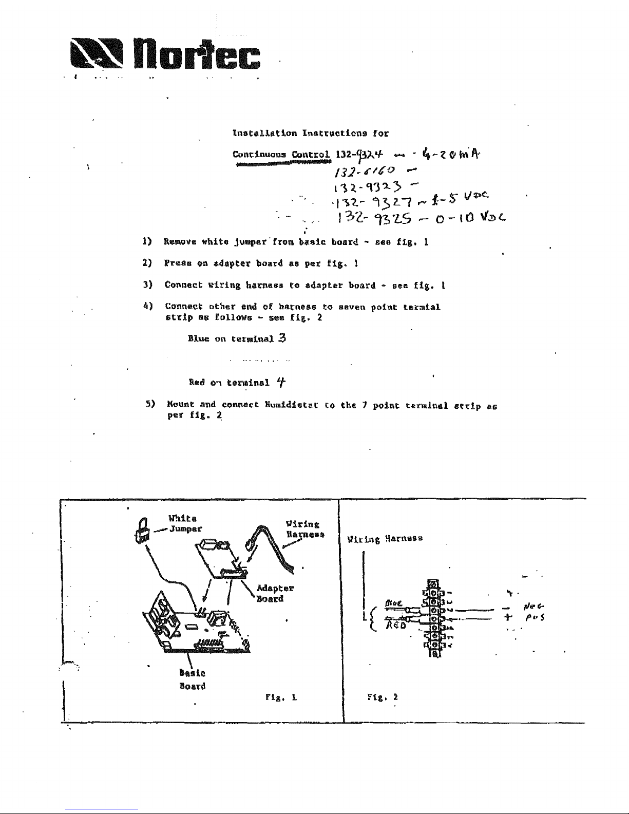
Installation
Inat~uetien9
for
CondnuOWl
~~P:0J-f
132-']3)..
if
- .
..
...
Z
CI
M'
A-
Il}
.•
1,0
..-
11~-,\1'l..>
-
_,
),
1.
~
~
3>
l. ( .....
/:-
5"
V
~c.
I
3l~
-=t~
'l.S -- 0 -
,a
\/:1)
l..
~)
Connect
other
end
of
hatness
tQ
BBven
pOint
~B~~tal
Gt~lp
as
follows -see
fiS-
2
Blue
on
terminal
2
5)
Muunt and
con~a~t
Humldist~t
to
thE 1
point
terminal
8t~lp
~s
per
U,.
~

RECeiVING
EQUIPMENt
~
/lGCklng
$lIp to
eMUm
ALL
material h85 been
genvlind.
2.
All
mateflal
shoftage~
are
to
be
reported to the
f$Ctul}' _11hlo
48
hours from receipt
01
good$.
IIIORTEC aSsume9
no
responsibility
for
any
material
shorta9OS
beyond
."Is
pertod.
3.
.
Inspect.
shipping crale(s) for damage
anCi
nole on
. shipping waybill accordingly.
4.
5.
Aftef'
uncratlng,
inspect
unit
for
demage
and If
~
ie
found,
nollfy
the shipper promptly.
AU
NORTEC PRODUCTS ARE SHIPPED ON
AN
F.O.B. FACTORY BASIS. ANY
"NO
ALL
DAMAGE,
S,.EAKAGE OR
lOSS
CLAIMS ARE TO BE MADE
DIRECTLY
TO
THE
SHIPPING
COMPANY.
PRE·INSTAl.LATION
CHECKPOINTS
1.
ConflMllhat
the "Ollltg8 afld pha$e
of
th4il
un
It
cor·
tespond$ with available voltage and phase.
t
Enwm
that th&
(U"::!
l11atn
breaker
15
of
liufllclst1t
size
to
handle
th~
mallimum
fuse rallng
iI9
IndlcatlHd
on
the
8pecHtcatJon
labat.
....
OT01
t-i'1lH
WATI'.ft
.
u;:va..
--,.......~~
I!IIDICATOR
"
LIGHT
,_·./.V.RGE
. ::' ,S!O£
ACCE:SS
.
'<'.
• :ro!t EllS'"
..
::.'!It4STALLATION
:.:'j
. '-,
WiTH
··
...
utO-AOAPmIE-·
CONtROL
1
MOUNTING
PROCEDURE
1. LccatlOf\
C)f
linit
should
be as close
to
and
b$low
ste.tun di5tdbu!or location ~ poulble.
2.
Prov~de
a Illlnhn!.lm cfeamnclil
of
24"
(600 mAl}
to
the
rlght of the l:nlt and a minimum
cf
30"
(750
mm)
if' front
of
ttoe
unIt, Refer to Diagram 1.
INSTALLATION CtEAMNCEIi
I/II///ILI
3.
!f possible, avoid locat:ng humidifier more than
35
iS$t from - steam distributor location.
At
this
distance, flet
O~lpiJ~
will
be
approximately i!8%
of
unit
capacity.
as
a JesuIt
of
cond4m3ation
I()$$e!il.
Refll.
to
Chart 1
and
to
steam
ilose
sectiOf\ .
UNIT
CAPACltv
CORRECTION
fACTORS
DlS1ANce
Qf
Sl'E4!i4
UN'"
O,STRlUlHOR
fROM
Cl\tllNU
cp.PI'cnY
COIIRECflOIll
((0
METUIS
FAClOR
010.
1!)
G
to
4.6
1.00
15
to
20
4.6
to
0.1
.
0.97
21
to
26
i
I
6.4 tQ
7.~
0.94
Xl
ttl
3'l
8.2
10
10.1
0.00
CtilaAT1
UNIT CAPACITY
COA~ECTt0f4
FACYORS
· 4.
Where
possible.
moont
unit
al a hvlght
conllenhmt
for 5efll'C!nt.
·
5.
Mour.ting bracket provided
shOUld
be
securely at·
tachod
Qpatn
ttdge ulW'ards. horizor.taily.
using
3
fsmener'3
to 8
vertlcat,
solid
M/ilCII.
See
Diagram
2.
6.
Make
SYnJ
unit
Is
1$1101.
·
7-
DO
not
mQunt
unit
on
twt
surfaces
Of
wlwre
temperatuiVS excHd 180
Q
F t82
411
C).
1.
2.
3.
4-
5.
6.
DlAGMII2
WAI.lllflACKEf
(FAC1()Jf\l
SUf'PtlB)l
WAlL
I'mAdCU
MOONTlNO
DIETM
\flAm
SUPPllf AND
DIWN
WATER
SUPPa..
y
Standard
fll!
valves
are
sized
101'
water prnuuros
ranging betwMn
30
and
85
psi.
FOI'
other
p!1$$Sure
eol'Jdltlons, consult factoI)'.
An
ext
....
altn-line
water
filter
Is
moommended
for
~
",hero
the
water
has
a high undissolved
mlnf#al conteM.-
Consult
f.aeIO~
about
accesmxy
WIMer
ttlter
(Part
No.
132-9506).
00
NOT
UR
sofiE/fled, de-lorl\l$d
or
any Olher type
of
pm-tre.
water lSupplles. Softening agents
~
millerats
blat
add
soelum
to give water an
unacceptably
high
(;onduetlvlty.
00
NOl
UN
a
hI::It
water supply
to
the unit. Minerals
In SUIJpumloo
will
eventually plug the till
valve.
An
IsoaatlRg gate valve
should
be
Install~
11'1
the
aupply
II""
to the unlt.
Use
14
•
dlm'neaer
water
line
from
potable
cold
water
source
to
the
unit.
2
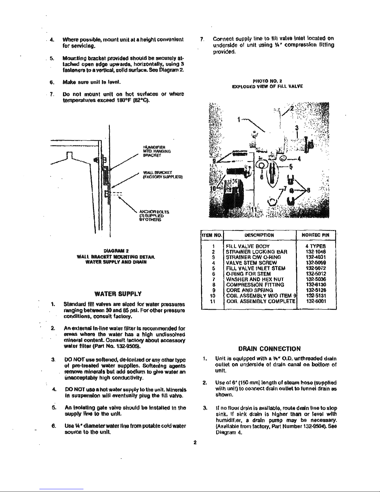
7.
Coi>nect
supply
line
\0
Ull
va\~e
inlet
located
on
u:t~rslde
of
lI!'1lt
using
1flI7
eompr~lon
fitting
provi<!ed.
ITeM
No.
PHOTO
NO,
2
EXP1.0DED
ViEW
OF
Fill
VAL"[
DE$CRI~TION
i'40nrEC
PIN
I
1
FilL
VALVE
BODY
4
TYPES
1
2
STRAiNER
LOCKiNG
eAR
132-10118
3
STRAINER
CiW
Q.f;lING
132-4031
I
4
VAlVE
STEM SCREW
132-5069
5
ALL
VALVE
If\,Ilt:T
SlEM
132-5012
6
O-RING
rOR
STEM
132-5012
1
WASHER
AND
HEX
NUT
132-5036
8
COMPRESSiON
FITTING
13C6t30
9
CORE
~ND
SPRING 132·5126
10
COIL
ASSEMBLY
W/O
ITEM
9
132-5131
11
COil
ASSEMBLY
COMPlETE
132-6001
DRAIN CONNECTION
1.
Unit
is
oqulpped
with
a l'II" O.D. ur.threadsd drain
outlet
on
u~derslde
of drain canal
on
boUom
of
unit.
2,
Use
ol
6"
(150
mm)
length
cf
sWam oose ($\lpplied
will'!
unit)
to
ooar.eGt drain
outlet
to
funnel
drain as
shown.
3.
If no
floor
d(~;n
is
avt.lIablo. route dmtn line
to
slop
sil'1k.
If
sink
d:a1n
is higher than
or
level wfth
humidifier,
ill
drain pump may be neceasary.
(AvC!lIabie
from factoI)', Part Number
132·9504}.
See
Oillgfam 4.
r!".-
CAUTION;
1
-
.....
i
"",
..
coPf'EA
ALTI;~NAr~
OM!:'.
(BY
OltiEHS;
Oraln
water
from
humldlfer
Clln
be
WJry
hQl.
For
:safety
masons, water should !lot dfaln Into sinks
usE!d
fro<
quenlly by personnel.
~
OUE
TO
MAIN
WATER
TEMI'£HA'I'U~.
NOT
AI.i.-
CONDEt4SATE
P\Jtaff'9
AM
SUlTA8lJ:_
CONSUlT
F~TOhY,
STEAM
DISTRIBUTORS
Each
cyR""r
out;,. requires a minimum
Of
orle
(1)
steam
dlslrtbutor.
/Iotly
Ol'\e
outlet
I1\IIIY
be divlded
Into
multiple
branch-.
eaeh
mqulring
an
addltloniil BtNm dl$trlbutor •
.
Steam
!!JupplY
'tees'
am
available
for
this
purpose, (See
i\CGflSQfIes
secdon
01
Product Catalogue.)
STEAM
DISTRIBUTOR
LOCATION
1. Stoam distributIon
can
bl' mounted In supply
or
t'8\um
air
Wets.
Propel
location;!
oonalder
duCt teMperature. air
flow,
A.M.,
o,,~
air Intak&,
etc.
Additional
details
are
local
.
on
fallowing
pages. Commit factory
or
local agent wIth
questlona.
3
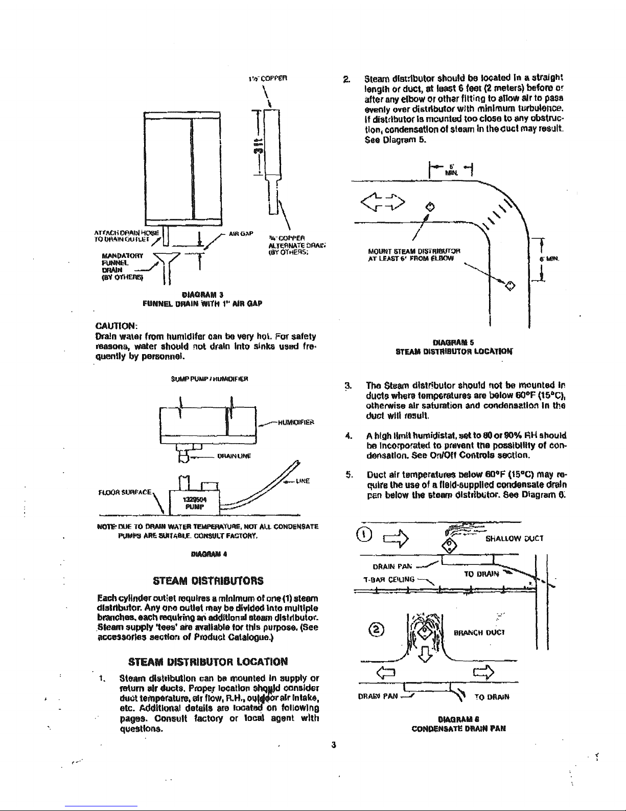
2. Steam distributor should
be
l()¢alad
In
Ii
straight
length
of
dUCt,
at
least 6
teal
(2
meters)
before or
after any elbow or othar fitting
to
3"01"
air
to
pass
evenly over distrlbutOf with
minimum
tl.lrbu*ence.
If
distributor
Is
mounted
too
close
to
!:iny obatruc-
tlon,
condensation
of
steam
In
lhe(luct
may
result
See
DlagnJiTI
5.
MOlmT
IiTI:AM
D'S"i~I8UTOtl
AT
lIlAST
t;'
mOM
f;UIOW
DIAG"ARIII5
STEAM
DISTRIBUlOR
LOCAnot4"
t
(I"
WIN.
1
3.
The
$team dlstrlbutor
shou1d
110t
be mounted In
ducts
wOOrtI
tell1fJ6ratures
are
below
60°F
(U;."·C).
otherwise
air s ..
duration
3I\d COIldensation
In
tht'l
duct WIll rosull,
4.
5.
A high
limit
humidistat. '*
to
80
Of
90% RH should
be
Incorporated
to
pr."ent
ttl"
posalbility
of
eon-
dMsllUon. See OnlOff Controls section.
Duct
air tempera.1uM
lHdow
60°F
(15°C)
may
m-
q\Jlrs
the
use of a fleld·supplled condensate
dn,ljn
p~n
bttlow the steam olstrlblitor.
See
Diagram
6~
-(
>
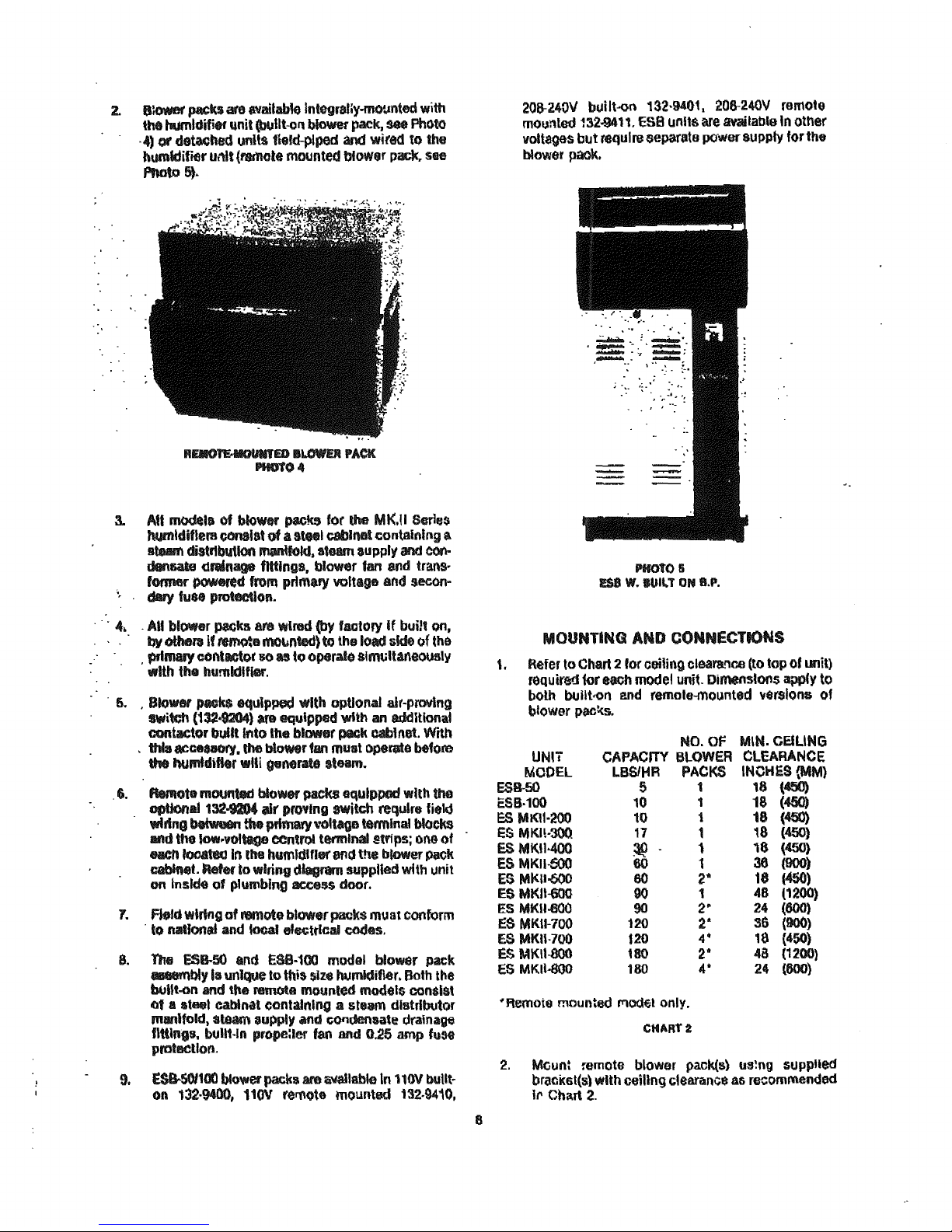
2.
8~
packs
aI'tl
available
Integr3liy-mO'.mted
with
the
twumldifi8f
Qnit
(blIlit-oll blower pack,
see
ptlC~to
,4)
Of
de~h8d
units
fiefd-plped
and
wired
to
the
humidifier
IJMt
(remote
mounted blower
pack,.
see
Photo 5).
3.
AU
modela
of bIoWItf'
packs
tor lhe MK.II Seril3$
Jwmldiflera
conalst
of
a
It"1
cabinet
containing
III
atoM!
distl1bt.tt1oo
manijoW.
steam
aupply
and
COt'\-
denNte
drainage
flttlng8, blow.,r fan 8fIti trans-
former
~ed
from
prtmaty voltage
and
secon-
dary fuM protection.
. .
4. . AU
bl(Wller
p.aeks
are
wlllld
(by
factolY
If
built
on,
by
othelIlf
~a
mo~nted)
to the
load
side of
the
, prlmary
conlactor
80
as
to
oporat(l
Slrm;ltaneouslv
"Ith
the humidifier.
.
6.
,Blower
_Its
equipped with optional air-proving
iIIwitdl (132,9204) at'8
equipped
with
an
additional
cootactor built Ittto the blower r»ek cabinet. With
.
this
#Cft$8Cry.
the
blowr
fan must operata before
the hutnldifter
wlli
generate
steam.
.
6.
FCefflote
m~ted
bluwef
packs
GC4ulppec:!
with too
optional 132C04 air proving switch require field
"'ring
~
the
primafy volt_ge terminal blocks
IIIII'Id
the
low-voltage CCntl"oIlermlnai
!trips;
one
of
each
too4*
In
the humldtfl9l"
&fl13
the blower pe.ck
cablMt.
Refer
to
wiring
d~
supplied with unit
on
Ins~
of
plumbing access door.
1.
ReId
wkiflg
of
remote blower packs
mu
at
cooform
. to
rudfonal
and
10GaI
el8Cttlcai
codes,
8.
nm
esa.50
and
ES8-100
mooal blower pack
.-robly
Is
unique
to
thi$
$ize
humidifier. Both the
buUt-on
and
the
remota
mounted models consist
of
II
ateet
cabtnil
containing a steam distributor
manifold, steam 3upply and
cOf1denaate
drainage
flttlng8.
buU1·ln
propeaer fan and 0.25
amp
fuse
protaclloti.
9.
ES8-5OI100
blower
packs
am
~Iahle
In
110Y
built-
on
132·9400,
110V
remote mounted
132.9410,
8
20B-240V
built-oo 132·9401. 206-240V remote
mounted
~32-9411.
ES8unlt$
are
tmlilabl9ln
other
voitages bot require separate
pOWefSUPPIy
forth.
blower
pook.
PHOto
Ii
ESe
W. BUILT
ON
8.P.
MOUNTING
AND
CONNECTIONS
1.
Refer to Chart 2 for ceiling cleara..,oo (to top
01
unit)
required for
each
model
unit. Dimens!oos appfy to
both
btJllt.-ol'\
end
remote-ffiQunted
'1en'dons
of
blower
pacl<s.
UNIT
MeDEL
ES8-50
ESB·100
ES
MKU·2{)O
ES
MKI!·300
ES
MK!I·400
ES
MKII-600
ES
MI<II-600
E5
MKII-600
ES MKlI«lO
ES
MKII-700
ES
MKII-700
E$
MKII-OOO
es
MKU4lOO
NO.
Of
M\N.
CEILING
CAPACITY
BLOWER
CLEARANCE
LBSlMR
PACKS
INOHES
(MM)
S 1 18 (450)
10 1
18
(450)
10 1
18
(450)
17 1
'8
(450)
~
1
18
(450)
60 1
36(900)
60
2"
18
(450)
90 1 48 (1200)
90
2'
24
(600)
120 2" 36
(900)
120
4"
18
(450)
180
2'
48 (1200)
180
4'
24
{600}
'Remota
mounted
rrlO/'Jf;I
only.
CHARf2
2.
Mounl remote blower pack(s)
us~"g
sUpPlied
bracKsl(s)
with
ceiling
cleariinC$ ali recommended
II'
Chart
2.
BLOWER
PACK
.
STEAM
HOSE
CONNECTION
1. All built-on blower
pack~
are
lactory
HUed
with
all
steam hose connections.
No
further
work.
Is
required.
2. Remote mounted
blower
packs require removal
of
the
bottol'll
COV9rpiate
to
gain access
to
the
Stilian1
manifold fltting$.
Fe!i!d
steam
supply
and
conden-
sate f9tum hoses through appropriate holes
In
bottom
plata and
replace
bottom
plattt. For steam
and ()(';n(lensate
hose
rouling, follow steps outlined
In
l)team
8uJ)ply
hose
routl1\9
section, !'age
6.
ELECTRICAL
CONNECT10N
. 1. Use 16
ga.
or
heavier wire
for
power
connecllon
from
tt.WJI1I!Ul1
block
of
blower pack
to
fuseltenTIlna!
block
It'lsJde
electrical
section
of
numldlfler.
2.
Use 16
gao
wiro
to
connect from ground clarop
of
blower
paek
to
ground clamp provided In tl'le
eltlCtrical
cOr.lpartrmont
of
the humidifier.
3.
All field
wiring
shoUld
be
encased
in
conduit
and
COnform
to
:1atlonal
and
lOCal
building
codes.
PRIMARY
VOLTAGE
WIRING
TO
UNIT
1.
Check
and
et'Isure
that
available
VQltago
and
phase
corresponds
with
operating voltage and
ph~
of
iJolt.
2. Ensure tl'lat
an
adequate eef\lice Is aviidlable
to
Cat!Y
full unit
amperage
drawn
as
specified
by
fusa
size
on unit nameplate,
3.
A fused disccnnect
breaker
~mbly should be
installed to
protGCt
unit
and
to provide corr.pl8te
system shutdown during periods
of
non·use.
4.
Recommended fuse size
for
disconnect
1$
stated
on
unit
nameplate and
1ft
product
catalogue.
5.
COOTlect
cabloet
grounti terminal to ground. Do
NOT use neutral wire
of
fQurwlre supply as ground.
6.
Single pha5e
lInlts
INiY be
run
On
3 phase power
but
load may unbalaoce power grid.
1.
Never use the neutral wlre
of
a 4
wlr~
system as a
power lead connection
with
thu
exC41ptiOll
of
'E7V
and
347\1
tapped
from 480V and 575V !'el.'pootlvely.
8.
PoW$r
leads are connected
to
thliJ
primary terminal
blQi!k In
the
electrical
section
through
the
knocl<outs provided in the
bottom
plate
of
the
unit.
9.
Wiring
sims
shouid
be
In accordance vrith national
and
loc;a\
eleotrlcal codes
arm
by·laws,
unit
elec.
trical
Co<S$S
aM
by-laws.
9
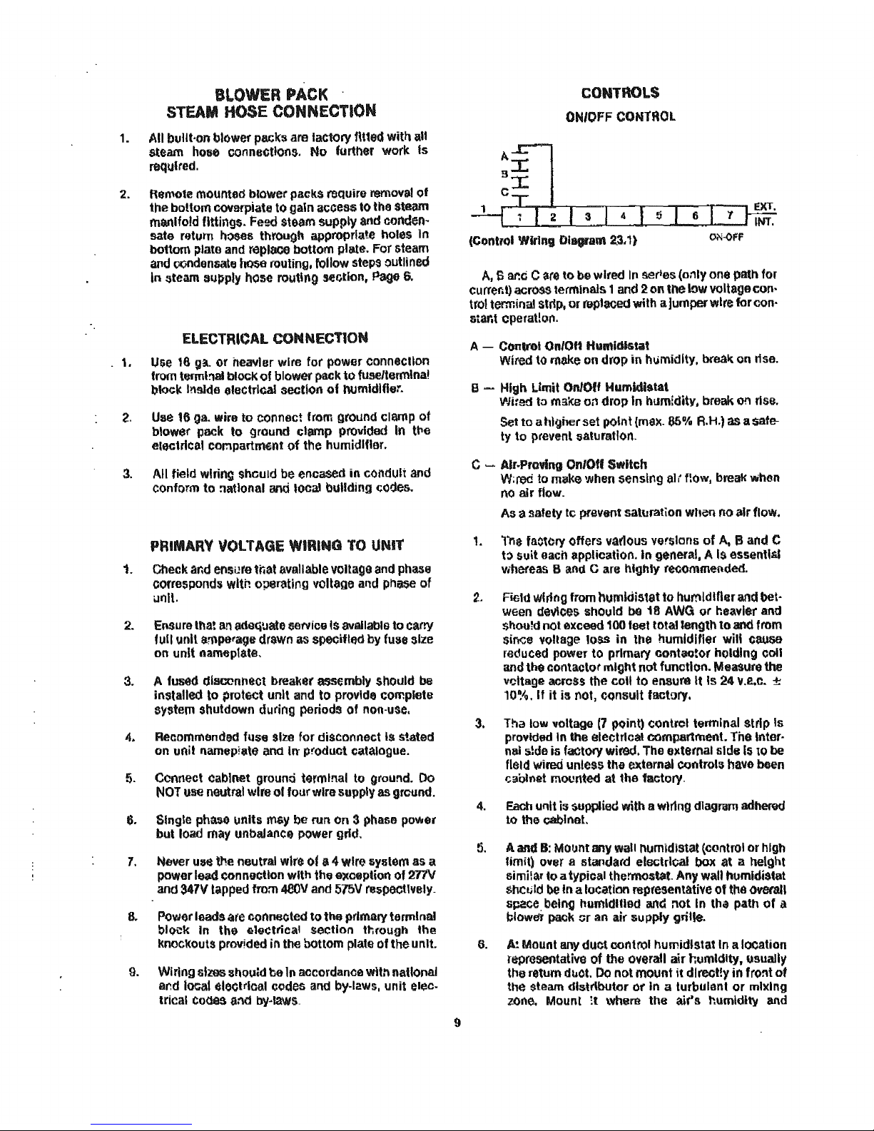
CONTROLS
ON/OFF
CONTROL
(ContfC)1
Wiring
D100ram
2.3,1)
A,
6
a~c
C
are
to
be
wired In series (o:'Ily
one
path for
cu
rrer;
t)
acrQS.S
terminals 1
and
2 on
tM
low
voltage con·
trol terminal strlp. or replaced
wlth
a jumper wire for con-
&tar.t cperat!on.
A - Control On/OH th,midlsta1
Wired to make
on
drop
in
humidity. breal( on rise.
S - High
L.lmit
OnlOff
Humidistat
Wired
ta
make
0;'1
drop
In humidity, break on rise.
Set
to
a higher set point (max.
85
1
/0
A.H.)
as
a safe-
ty
to
prevent
~aturatlon.
c
~
Alr.Proving OnlOff 5wttch
1.
2.
3.
4.
t'
:.I.
6.
W:red to make wh8n sensing
alt
flow,
break
1Aihen
no air flow.
As
a safety
Ie
prevent saturation when
no
air
flow.
Tne
factery offers vat10us versions
of
A, B
and
C
t:>
suit
eaen applicatioo.
In
general. A
1$
essentlsJ
whereas B anti C are
highly
recomm~{\ded.
Field
wiring
from
humidistat to humidifier
and
bet-
ween de'l\ces should be 18 AWG
Qr
heavier and
sl"too!d
not
exceed 100
188t
total
length
to
all<!
from
SiflGS
vQJtage
loSS
in
tile
humidifier
will
CIlUOO
re(juced power
to
primary
contaotof
holding
coil
and the contacto(
might
not
function.
Measure
the
v~ltage
acrcss
the
coli
to
ensure It 1524 '1.2.0. ±
10%.
If
it
is
not, Consult factory.
Tha low voltage
17
point)
contrel
terminal
strip
Is
provided In the electrical compartment.
Tne
Inter·
nal 5!de
is
factory wired. The oxternal sldu Is
to
be
field wired unless the extern31
CCJntrol~
have
been
r..llblMt r.loonted at the factory.
Each unit is supplied
wUh
a wiring diagram
adhered
to
the cabinet.
A
and
B:
MOl)nt
any
wall Ill.lmidJstat (cQntrol
or
high
limit) over a standard
electrical
box
at a height
similar
to
a typical thermostat.
Any
wall
humidistat
ShCtjld
be
In
a location mptcsentative of
tM
overall
space bell\{j
humidified
and
not
In
th.
path
of
il
blower pack
or
an air su pply grille.
A!
Mount any
duct
control
humidistat
In
a location
r~reseotativa
of
the o\lerall
air
humidity. usually
the
retum duot.
Do
not
mount
it
dlroot!y
in
frollt
of
the
$team
distributor
Of
In a turbulent
or
mixing
u>oe.
Mounl
;1
where
the
ai(s
humldltv
and
 Loading...