

Page 1

STEAM
DISTRIBUTORS
ASD / BSD / CSD
Steam Distribution
Installation Manual
IMPORTANT: Read and save this guide for future
reference. This guide to be left with equipment owner.
1506117-B
Page 2

Table Of Contents
INSTALLATION .....................................1
RECEIVING & UNPACKING EQUIPMENT .....................1
PRE-INSTALLATION.................................1
STEAM LINE INSTALLATION ............................1
GUIDELINES ...................................1
CONDENSATE RETURN GUIDELINES FOR MAIN STEAM LINES ..........2
DISTRIBUTOR MOUNTING...............................3
VERTICAL AIRFLOW ..................................4
HORIZONTAL AIRFLOW ................................5
VERTICAL AIRFLOW ..................................6
DISTRIBUTOR MOUNTING - HORIZONTAL & VERTICAL FLOW ...........7
DISTRIBUTOR MOUNTING...............................7
EXPLODED VIEW ....................................8
Page 3
INSTALLATION
Chart #1
Steam Line Material
RECEIVING & UNPACKING EQUIPMENT
1. Check packing slip to ensure ALL material
has been delivered.
2. All material shortages are to be reported to
Walter Meier (NORTEC) within 48 hours
from receipt of goods. Walter Meier
(NORTEC) assumes no responsibility for
any material shortages beyond this period.
3. Inspect shipping boxes for damage and
note on shipping waybill accordingly.
4. After unpacking, inspect equipment for
damage and if damage is found, notify the
shipper promptly.
5. All NORTEC products are shipped on an
F.O.B. factory basis. Any and all damage,
breakage or loss claims are to be made
directly to the shipping company.
6. Each distributor is provided with: installation
manual, one hose cuff, and two hose
clamps.
PRE-INSTALLATION CHECK
1. Ensure the total capacity of the humidifier is
not higher than the allowable maximum
steam capacity of the distributors used.
ASD 10: 22 lbs/hr (8 kg/hr)
ASD: 25 lbs/hr (9 kg/hr)
BSD: 35 lbs/hr (13 kg/hr)
CSD: 115 lbs/hr (45 kg/hr)
STEAM LINE INSTALLATION
Short run
< 10 feet
Steam
Hose
üü ü
Copper Tube Stainless
Steel Tube
(3 m)
Long run
> 10 feet
üü
(3m)
DI/RO
water
ü
4. Consult the following pages for step by step
distributor installation starting with Figure
#1.
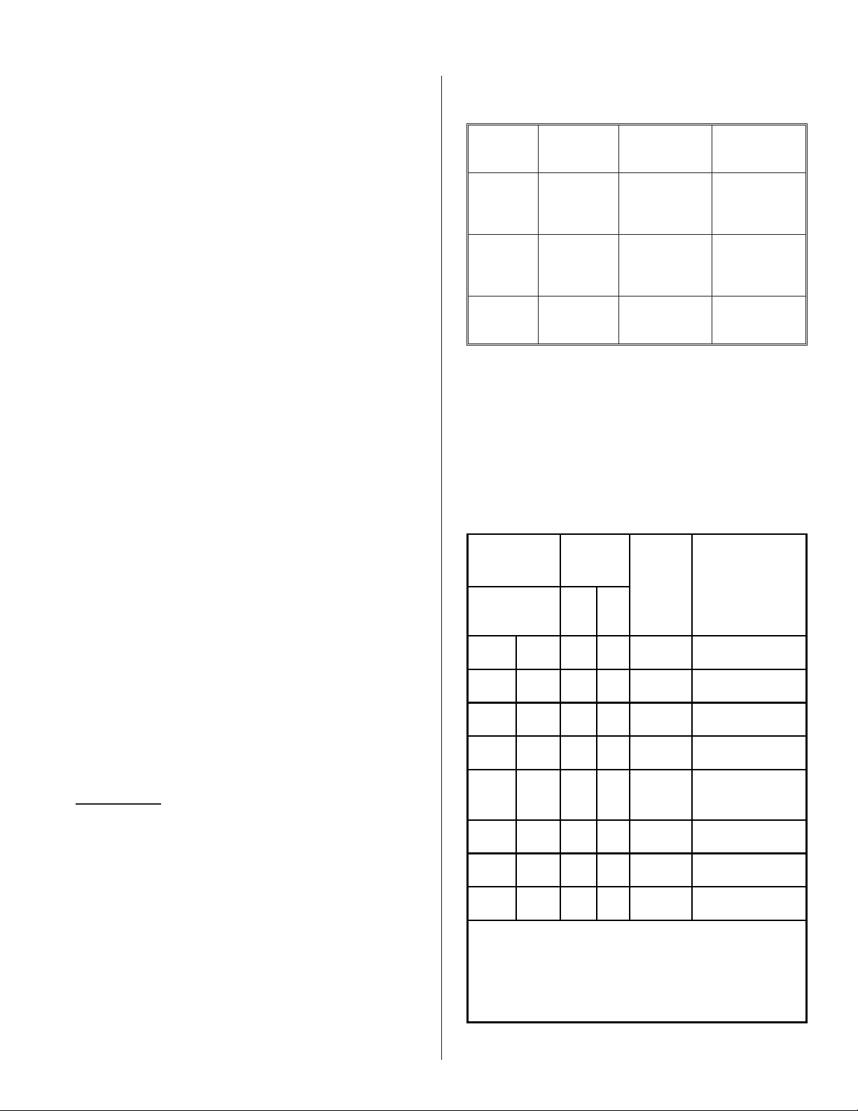
5. Consult the charts below for steam and
condensate sizing guidelines when using
steam distributors.
Chart #2
Recommended material and size for steam run
Load Steam Run
lb/hr kg/hr ft m
0-30 0-13 0-10 0-3
0-30 0-13 10 + 3 +
0-30 0-13 0-10 0-3
0-30 0-13 10 + 3 +
Steam
Line
Material
Copper
tube
Copper
tube
Stainless
Steel tube
Stainless
Steel tube
Steam Line
Description
3/4" MED-L Tubing
(7/8" O.D.)
1” MED-L Tubing
(1 1/8" O.D.)
7/8” tube x
0.049” thick.
1 1/8” tube x 0.049”
thick.
GUIDELINES
1. Nortec steam hose should only be used on
short steam runs below 10 feet.
2. Ensure that no condensate produced in the
steam line will remain trapped. Steam
naturally flows upward and condensate
naturally flows downward.
3. See material recommended for use in the
chart below. To eliminate the metal
corrosion, Nortec does not recommend the
use of steel piping.
30-100 13-45 0-20 0-6
30-100 13-45 20 + 6 +
30-100 13-45 0-20 0-6
30-100 13-45 20 + 6 +
Please note that options shown in a bold-italic font requires
that reducers be used at both ends. These extra large sizes are to
allow for better condensation removal in long steam runs. These
sizes will not permit you to use hose coupling to connect your
self to either humidifier or distributors.
Copper
tube
Copper
tube
Stainless
Steel tube
Stainless
Steel tube
1½”MED-LTubing
2” MED-L Tubing
-1-
(1 5/8" O.D.)
(2 1/8" O.D.)
1 ¾” tube x
0.065” thick.
2” tube x
0.065” thick.
Page 4
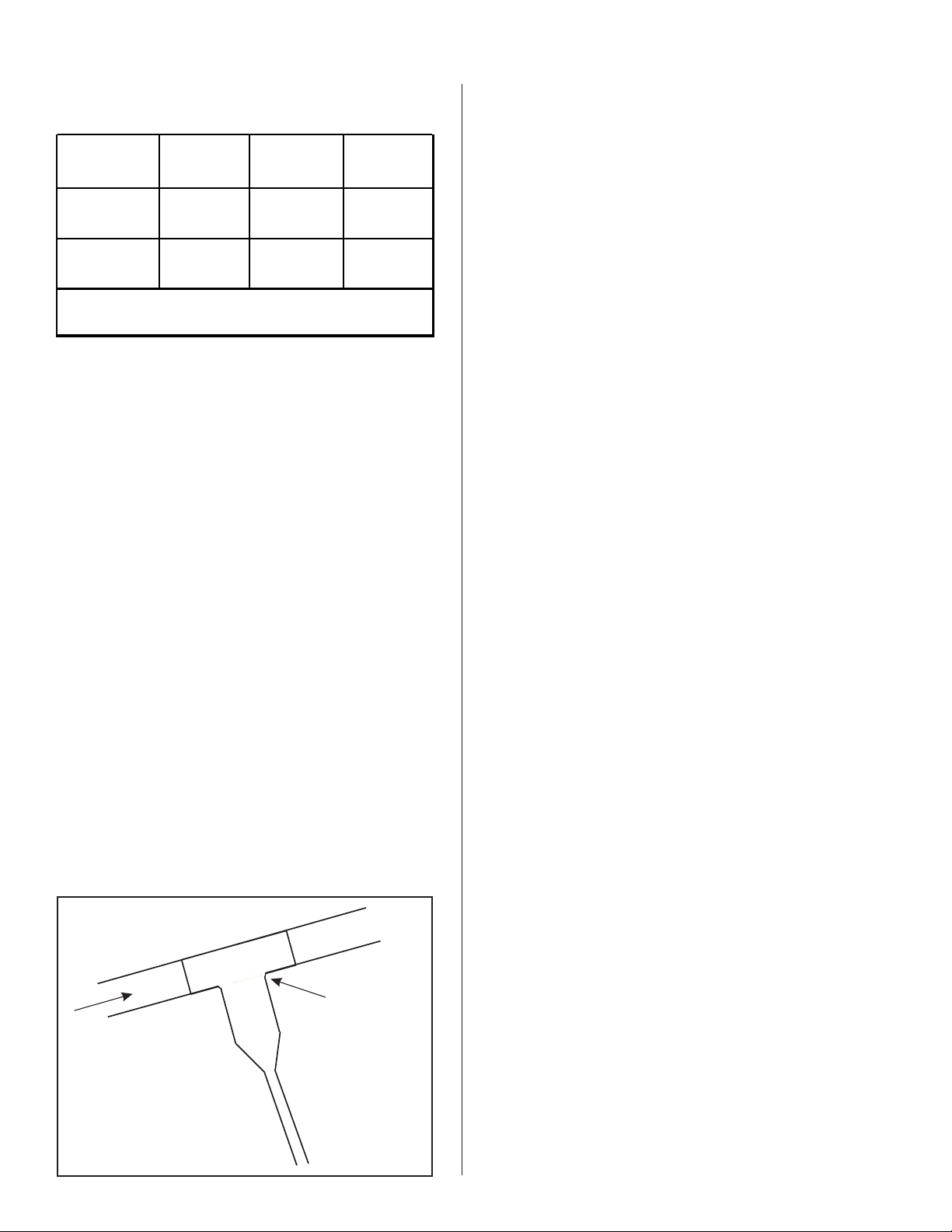
Chart #3
Recommended Condensate line at distributor(s)
Dispersion
Method
1 x Steam
distributor
3 x Steam
Distributor*
*When using more than one distributor, the condensate line
should be trapped before joined together.
Condensate
Hose
3/8" Nortec
1328840
3/8" Nortec
1328840
Copper tube
1/4" MED-L
Tubing
(3/8" O.D.)
1/2" MED-L
Tubing
(7/8" O.D.)
Stainless Steel
tube
3/8” tube
0.049” thick.
5/8” tube
0.049" thick
CONDENSATE RETURN GUIDELINES FOR
MAIN STEAM LINES
1. Use vertical condensate leg of distributor
only. Do not over-tighten clamp.
2. Drip stations on steam mains must be
located at all low points in the system, at
each elevation change and or directional
change.
6. Vertical drop of the drip station should be
1.5 times the diameter of the steam main
but no less then 12”.
7. At the bottom of this drip station is where
the “p-trap” is installed. It is to be 2” larger
then the duct static duct pressure.
8. All distributors must be individually trapped.
3. Horizontal runs of steam must have a 2”
rise per foot (10º) when flow is going
upwards from drip station and the steam
run is to fall ½” per foot (2º) when flow is
going downwards to drip station.
4. In a horizontal run of the steam main, drip
stations must be located at regular intervals
of 20 feet.
5. The drip station itself is a section of piping
connected to the bottom of the main. A full
size tee must be used to create a drip
station to allow the condensate to fall in the
drip station.
Figure #1
Drain Tee
Full Size
Drain Tee
-2-
Page 5

g
Figure #2
Distributor Mounting
A
HORIZONTAL FLOW
Use vertical
condensate leg
only.
To be 2” (50mm) longer
then duct static pressure
or minimum.
GO TO
Use vertical
condensate leg
only.
To be 2” (50mm) longer
then duct static pressure
or minimum.
min.
Use vertical
condensate leg
only.
100
m
”
6
VERTICAL FLOW
min. 2º min. 10º
)
m
.
m
n
i
0
m
0
R
min. 10º
”min.(914mm)
12
m
m
0
5
1
(
n
i
m
”
6
3
(
”
2
1
)
12” (300 mm)
Nortec
Use vertical
condensate leg
only.
m
”
6
Humidifier
NHB, NHP, NHMC,
RESDELUX ONLY
C1
min. 2º min. 10º
)
m
m
0
0
3
(
”
2
1
min. 10º
”min.(914mm)
12
)
m
m
0
5
1
(
n
i
m
”
6
Nortec
Humidifiers
All Models
)
m
m
0
.
0
n
i
min. 20 %
Nortec Humidifiers
All Models
%
”min.(914mm)
12
)
m
m
0
5
1
(
n
i
n
i
m
”
6
3
(
Rm
(
12” (300 mm)
min. 10ºmin. 2º
”
2
1
0
5
1
12” (300 mm)
)
m
m
Use vertical
condensate leg
only.
GO TO
Use vertical
condensate leg
only.
min. 20 %
(
n
i
m
”
6
0
5
1
(
n
i
m
”
6
min. 2º min. 10º
min. 10º
”min.(914mm)
12
)
m
m
0
5
1
(
n
i
B
min. 10º
”min.(914mm)
12
)
m
m
0
5
1
min. 10º
”min.(914mm)
12
)
m
m
)
m
.
m
n
i
0
m
0
R
3
(
”
2
1
Nortec
Humidifier
NHB, NHP, NHMC,
RESDELUX ONLY
min. 10ºmin. 2º
)
.
m
n
i
m
m
0
0
R
3
”(
2
1
Nortec
Humidifiers
All Models
)
m
m
0
0
.
3
(
n
i
”
2
1
Rm
Nortec Humidifiers
All Models
m
0
5
1
(
n
i
m
”
6
12” (300 mm)
12” (300 mm)
min. 10ºmin. 2º
12” (300 mm)
)
m
GO TO
C1 B
GO TO
For long steam runs, condensate trap with full size tee, must
be used every 20 feet to eliminate condensate. Follow same
rulesasabovefortraphei
ht.
-3-
Page 6

Figure #3
Vertical Airflow
B
Always align distributor holes so that steam is discharged
upwards to ensure condensate will remain in the distributor.
1
1x
2
+45º
-45º
3
GO TO
C2
-4-
Page 7

Figure #4
Horizontal Airflow
C1
Always align distributor holes so that steam is discharged
upwards to ensure condensate will remain in the distributor.
Template provided
81-...
41-...
6
1
m
m
m
m
3
4
8
1
.
.
.
6
1
.
.
.
/
4
1
.
.
.
m
m
6
.
3
H
¿
X
by Nortec in box.
61-...
81-
61-... / 41-...
...
3.6 mm
¿
XMin. HMin.
ASD
3” (76mm)
BSD
4” (102mm)
CSD
5” (127mm) 14” (356mm)
10” (254 mm)
ASD ø 1.7" (43 mm)
BSD ø 1.7" (43 mm)
CSD ø 2.4" (61 mm)
8” (203mm)
2/5H
2/5H
1/5H
A
A
B
2/3H
H
1/3H
H
5”m in.
AB
ASD: 5” 3”
BSD: 6” 4”
CSD: 9” 5”
GO TO
-5-
D
Page 8

Figure #5
Vertical Airflow
C2
Always align distributor holes so that steam is discharged
upwards to ensure condensate will remain in the distributor.
1/3W
W
2/3W
Min. W = 8” (203 mm)
GO TO
D
1/3W1/3W
H
1/3W
1/3W
WARNING:
·
These installation guidelines apply for duct velocities under 2000 ft/min (610 m/min), please consult factory
for higher velocities.
·
Please make sure no obstacles (elbow, filter, or diffuser) are located after the distributor in the direction of the
airflow closer than the absorption distance calculated for your application.
·
Unless you know the exact absorption distance required for the steam absorption into the air stream, the
distributor should be located at least 8-10 ft (2-3 m) away from any obstacle it may condense on (elbow,
diffuser, filter, etc.).
-6-
Page 9

Figure #6
t
Distributor Mounting - Horizontal & Vertical Flow
D
#10 Scre w
Use self tapping sc rews.
Mount
Level
GO TO
Distributor Mounting
E
Figure #7
E
5/16”
5/16” unc
Mandatory for Distributors longer than 36” (915mm).
-7-
Support Bracke
by Others
Page 10

ASD & BSD
1506162- Distributor End Cap Assembly
CSD
1506164 - Distributor End Cap Assembly
Distributor Core
ASD & BSD
1506161- Distributor Inlet Assembly
CSD
1506163 - Distributor Inlet Assembly
Exploded Views
December 18, 2002
-8-
Page 11

LIMITED WARRANTY
Walter Meier Inc. and/or Walter Meier Ltd. (hereinafter collectively referred to as
THE COMPANY), warrant for a period of one year from date of shipment, that THE
COMPANY’s manufactured and assembled products, not otherwise expressly
warranted, are free from defects in material and workmanship. No warranty is made
against corrosion, deterioration, or suitability of substituted materials used as a result of
compliance with government regulations.
THE COMPANY’s obligations and liabilities under this warranty are limited to
furnishing replacement parts to the customer, F.O.B. THE COMPANY’s factory,
providing the defective part(s) is returned freight prepaid by the customer. Parts used
for repairs are warranted for the balance of the term of the warranty on the original
humidifier or 90 days, whichever is longer.
The warranties set forth herein are in lieu of all other warranties expressed or
implied by law. No liability whatsoever shall be attached to THE COMPANY until said
products have been paid for in full and then said liability shall be limited to the original
purchase price for the product. Any further warranty must be in writing, signed by an
officer of THE COMPANY.
THE COMPANY’s limited warranty on accessories, not of Walter Meier’s
manufacture, such as controls, humidistats, pumps, etc. is limited to the warranty of the
original equipment manufacturer from date of original shipment of humidifier.
THE COMPANY makes no warranty and assumes no liability unless the equipment
is installed in strict accordance with a copy of the catalog and installation manual in
effect at the date of purchase and by a contractor approved by THE COMPANY to
install such equipment.
THE COMPANY makes no warranty and assumes no liability whatsoever for
consequential damage or damage resulting directly from misapplication, incorrect sizing
or lack of proper maintenance of the equipment.
THE COMPANY retains the right to change the design, specification and
performance criteria of its products without notice or obligation.
Page 12

Walter Meier (Climate USA) Inc.
826 Proctor Avenue, Ogdensburg, New York 13669
Walter Meier (Climate Canada) Ltd.
2740 Fenton Road, Ottawa, Ontario K1T3T7
Tel: 866 NORTEC 1 Fax: 613 822 7964
nortec@humidity.com www.humidity.com
PRINTED IN CANADA
 Loading...