

Page 1
Important: Read and save these instructions. This guide to be left with equipment owner.
Blower
Packs
Installation and
Operation Manual
Includes installation, operation
maintenance and troubleshooting
information for all atmospheric
humidifiers
2572641-B | 6 AUG 2013
Page 2

INSTALLATION DATE (MM/DD/YYYY)
MODEL #
SERIAL #
Thank you for choosing Nortec.
Proprietary Notice
This document and the information disclosed herein are proprietary data of Nortec Humidity Ltd. Neither this document
nor the information contained herein shall be reproduced, used, or disclosed to others without the written authorization
of Nortec Humidity Ltd. except to the extent required for installation or maintenance of recipient’s equipment. All
references to the Nortec name should be taken as referring to Nortec Humidity Ltd.
Liability Notice
Nortec does not accept any liability for installations of humidity equipment installed by unqualified personnel or the use
of parts/components/equipment that are not authorized or approved by Nortec.
Copyright Notice
Copyright 2013, Nortec Humidity Ltd. All rights reserved.
Page 3

Contents
Introduction .................................................... 1
Receiving and Unpacking ............................... 2
Before Installation ........................................ 2
Humidifier Components .................................. 3
RM-BP (Remote Mounted Blower Pack) ..... 3
NH-EL Space ................................................. 4
Models ........................................................... 5
Installation ...................................................... 6
Typical installation ........................................ 6
Location and Mounting: ............................... 7
Plumbing .................................................... 10
Electrical ..................................................... 11
Steam Lines ............................................... 12
Accessories .................................................. 19
Steam Adapter ........................................... 19
Blower Pack ............................................... 20
Startup/Operation ....................................... 21
Sequence of operation .............................. 21
Maintenance/Service .................................. 22
Troubleshooting ........................................... 22
Spare Parts .................................................. 23
Page 4
Introduction
CAUTION: Servicing
Humidity Ltd.
CAUTION: Electrical
CAUTION: Plumbing
All plumbing work should be done according to local plumbing code.
CAUTION: Installation
Disconnect main power before any servicing.
The plumbing and electrical compartments contain high voltage components and
wiring. Access should be limited to authorized personnel only.
During and following operation of the humidifier, the steam and components in
contact with the steam such as the blower pack, steam lines, steam distributors,
and condensate lines can become hot and can burn if touched.
Nortec Humidity Ltd does not accept any liability for installations of humidity
equipment installed by unqualified personnel or the use of
parts/components/equipment that are not authorized or approved by Nortec
All electrical work should be done according to local and national electrical code.
Electrical connection to be performed by a licensed electrician.
Plumbing to be performed by a licensed plumber.
Drain water from humidifier and condensate from blower pack can be very hot.
Do not drain to public sink.
Do not mount on hot surfaces.
Do not mount in area where freezing can occur.
Do not mount on vibrating surface.
Do not mount on floor.
1 | Blower Pack Installation Guide
Page 5
Receiving and Unpacking
Figure 1. Specification Label Location RM-BP and NH-EL Space
1. Check packing slip to ensure ALL material has been delivered.
2. All material shortages are to be reported to Nortec within 48 hours from receipt of goods. Nortec
assumes no responsibility for any material shortages beyond this period.
3. Inspect shipping boxes for damage and note damages on shipping waybill accordingly.
4. After unpacking, inspect equipment for damage and if damage is found, notify the shipper
promptly.
5. All Nortec products are shipped on an FOB factory basis. Any and all damage, breakage or loss
claims are to be made directly to the shipping company.
Before Installation
1. Ensure that available voltage and phase corresponds with Blower Pack voltage and phase as
indicated on Blower Pack’s specification label.
2. Ensure that the dedicated external fuse disconnect is of sufficient size to handle the rated amps
as indicated on the specification label. Refer to local codes.
3. Report any discrepancy immediately to the site engineer.
4. Ensure sufficient clearances will be available as described in the “Location and Mounting”
section.
5. Ensure steam lines can be routed to blower pack as described in the “Steam Lines” section.
Blower Pack Installation Guide | 2
Page 6
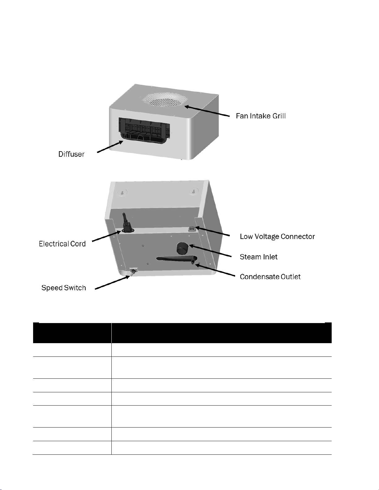
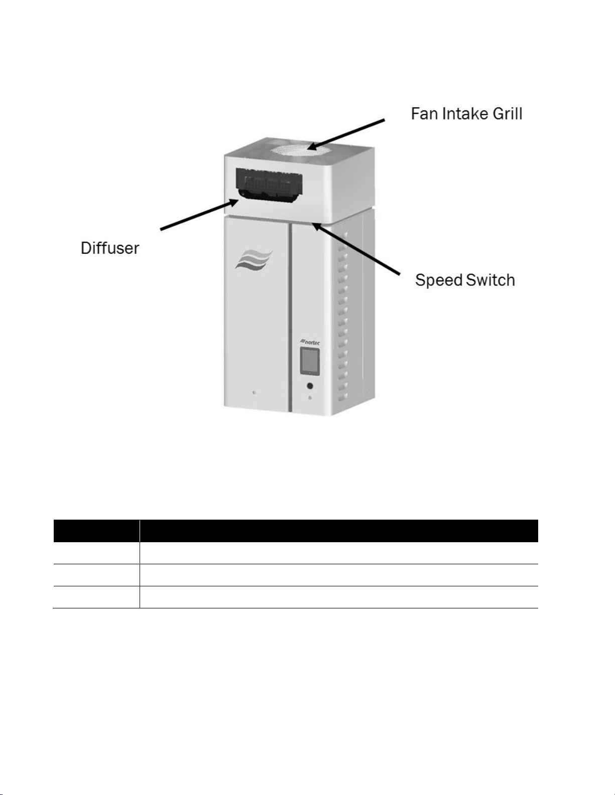
Humidifier Components
Component
Function of Component
Fan Intake Grill
Protects the fan from foreign objects
Speed Switch
Controls the fan speed between High and Low. High speed will generate a
louder fan noise but achieve best absorption performance.
Diffuser
Provides uniform distribution of steam from blower pack
Steam Inlet
Connects to humidifier steam outlet with steam hose
Condensate Outlet
Provides egress for condensed steam inside blower pack. Connects to drain
or drain water cooler
Electrical Cord
Used to provide power (115v) to humidifier
Low Voltage Connector
Provides feedback to humidifier when power is provided to blower pack
Figure 2. Humidifier Components RM-BP
RM-BP (Remote Mounted Blower Pack)
3 | Blower Pack Installation Guide
Page 7
NH-EL Space
Component
Function of Component
Fan Intake Grill
Protects the fan from foreign objects
Speed Switch
Controls the fan speed between High and Low
Diffuser
Provides uniform distribution of steam from blower pack
Figure 3. Humidifier components NH-EL Space
Blower Pack Installation Guide | 4
Page 8
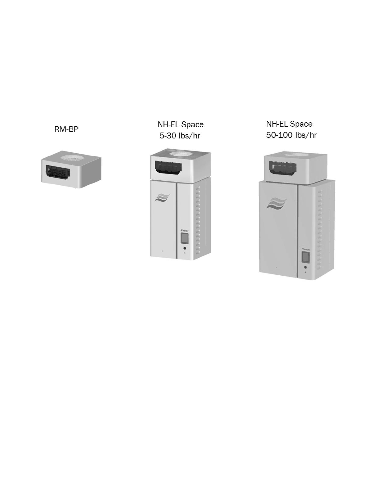
Models
Figure 4. Models for RM-BP and NH-EL Space
Blower packs are an optional accessory used to directly distribute steam to localized areas or in
structures that do not have a built-on air distribution system. The Remote Mounted Blower Pack
(RM-BP) model requires field piping to be completed on site. The NH-EL Space humidifier models
come pre-assembled with a Blower Pack mounted on the top. Both smaller steam capacity NH-EL
models (5-30 lbs/hr) and medium steam capacity NH-EL models (45-100 lbs/hr) can be ordered for
direct In-Space steam distribution.
For in-space distribution with large steam size humidifier capacities greater than 100lbs/hr, (Dual
cylinder NH-EL 150, 200, GSTC, SETC) , the RM-BP (remote mounted blower pack) must be added to
humidifier. See “Installation” section
5 | Blower Pack Installation Guide
Page 9
Installation
Typical installation
Figure 5. Typical Installation
Figure 1. Typical Installation
Blower Pack Installation Guide | 6
Page 10
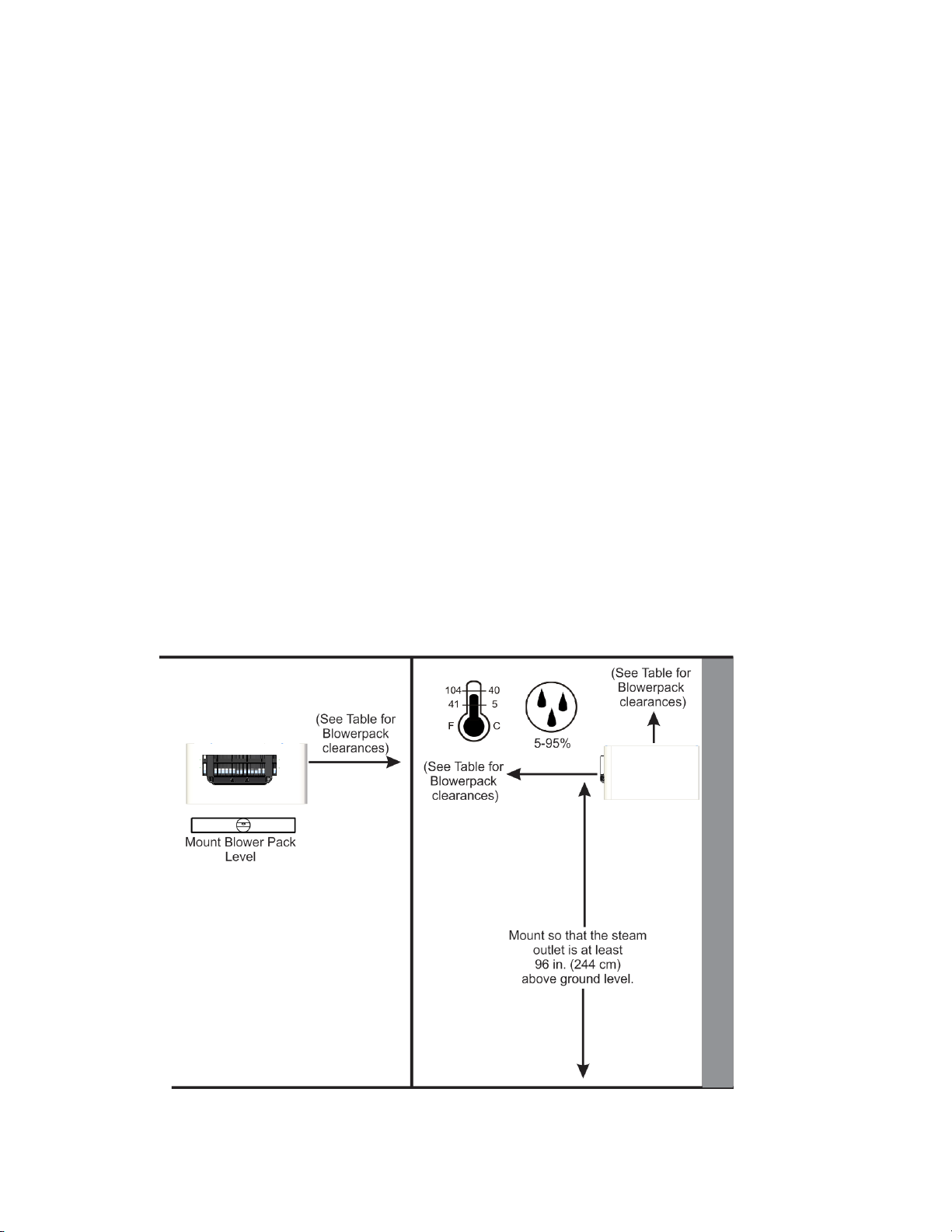
Location and Mounting:
Figure 6. NH-EL Space Mounting Clearances
NH-EL Space
Refer to NH-EL Installation and operation manual (2570435) for instructions on mounting the NHEL.
RM-BP
To wall mount the RM-BP, use 2 #12 x 3” long wood screws, supplied by others. These screws must
be fastened securely on a 2 x 4 wood stud or equivalent support. If any spacer material is used
between the bracket and the structural material such as drywall, increase the fastener length
accordingly. DO NOT locate the humidifier any further then absolutely necessary from the blower
pack location as net output will be reduced as a result of heat loss through the steam line.
Blower packs have hot surfaces that could result in burns if touched.
Mount blower pack on a suitable wall or vertical surface.
Clearance dimensions shown are for reference only and are the minimum required for
maintenance of the humidifier. Consult local and national codes before final location and
installation. NORTEC does not accept responsibility for installation code violations.
Install only in areas with ambient temperature 41-104 °F (5 – 40 °C) relative humidity 5 - 95%
(non condensing).
When possible, mount the blower pack at a height convenient for servicing.
7 | Blower Pack Installation Guide
Page 11

Keyholes are spaced 12 in. (30.48 cm) apart center to center. Insert screws into the studs until
Note: Use screws longer than 3/4” (7.5 cm) if drywall or other spacer is present.
Note: Do not mount on hot surfaces, where freezing can occur, vibrating
surface, or floor.
Figure 7. RM-BP Mounting Detail
there is 1/4 in. (0.64cm) of screw exposed. Be sure the screws are level to each other.
Raise the unit and place the screws through the keyholes. Make sure the unit is level, then
tighten the screws to secure the unit in place.
Place L Shaped brackets on top of the unit, with holes inline with the studs. Using the
appropriate sized wood screw, fasten the “L” brackets to the studs, securing the unit from any
upward motion
Blower Pack Installation Guide | 8
Page 12

Do NOT use blower packs as ducted blowers. The air volume from a blower pack is not sufficient
Humidifier
Capacity
lbs/hr (kg/hr)
Minimum
No. of
Blower
Packs
Min. Frontal
Clearance
Inches (cm)
Min. Overhead
Clearance
Inches (cm)
Min. Left side
Clearance
Inches (cm)
Min. Right side
Clearance
Inches (cm)
30 (13.6)
1
132 (336)
12(31)
12 (31)
12 (31)
100 (45.4)
1
Not
recommended
Not
recommended
Not
recommended
Not
recommended
Humidifier
Capacity
lbs/hr (kg/hr)
Minimum
No. of
Blower
Packs
Min. Frontal
Clearance
Inches (cm)
Min. Overhead
Clearance
Inches (cm)
Min. Left side
Clearance
Inches (cm)
Min. Right side
Clearance
Inches (cm)
30 (13.6)
1
120 (305)
12(31)
12 (31)
12 (31)
100 (45.4)
1
248 (630)
36 (91)
30 (76)
30 (76)
for proper operation in a ducted system.
Table 1: Clearances for Blower Packs on Low Speed*
Table 2: Clearances for blower Packs on High Speed*
*NOTES:
Nominal Conditions 72˚F (22.2˚C), 43% RH.
Low speed not recommended for 100 lbs/hr humidifier. Consult factory for recommendations.
Blower Pack should not be installed near cold surfaces or where dew point may be reached.
Higher humidity or lower room temperature may result in longer absorption distances.
9 | Blower Pack Installation Guide
Page 13

Plumbing
RM-BP Plumbing consists of steam and condensate line connections located at the bottom of the
blower pack. The steam line connection is of size 1.75” OD. The Blower Pack is designed to work
for up to 100lbs/hr. Ensure that the steam inlet on the bottom of the blower pack is unobstructed.
Figure 8. Plumbing Connections
Use Nortec Hose to connect to RM-BP steam inlet. A hose gear clamp can be used to ensure
tight fit. DO NOT OVERTIGHTEN the gear clamp.
The Condensate line should not terminate in a sink used frequently by personnel, or where
plumbing codes prohibit it. Route to a floor drain or equivalent for safety reasons.
Insure condensate line is adequately sized to provide free and easy draining and that an air gap
is installed as shown
Do not use hose other than Nortec Hose, See Table 1 for plumbing recommendations.
Blower Pack Installation Guide | 10
Page 14

Electrical
Figure 9. Electrical Connections
The RM-BP uses a 110-120V single phase power source and comes with a minimum 5 ft (1.5 m)
long electrical cord connection and termination.
Low voltage control wiring is also required between the blower pack and the humidifier (use class 1
circuit wiring). The Blower Pack low voltage terminal block consists of a plastic connector. Wires
should be run from the blower pack terminal block through the wire chase, and to the humidifier
landing on terminals 8 and 9 on the NH-EL low voltage terminal strip.
If used with other Nortec humidifier technologies, place low voltage connection in series with
humidifier safety loop.
Field wiring of remote blower packs must conform to national and local electrical codes. Refer to
wiring diagram supplied at the back of this manual.
11 | Blower Pack Installation Guide
Page 15

Steam Lines
Prior to connecting the steam hose ensure proper inlet size.
NH-EL
Maximum Steam
MED-L
Stainless
Possible Steam Losses
Model
Line Length
Copper
Steel
(based on 1” insulated copper
pipe)
ft
(m)
Tube
Tube
lb/hr/ft
(kg/hr/m)
5**
7
(2)
3/4
0.875 X 0.049W
0.06
(0.09)
10**
12
(3.5)
20**
17
(5)
30**
22
(6.5)
50
43
(13)
1 1/2
1.75 X 0.065W
0.11
(0.16)
75/150***
47
(14)
100/200***
50
(15)
Oversized Steam Line (Use for longer steam runs)****
5**
14
(4)
1
1.125 X 0.049W
0.06
(0.09)
10**
24
(7)
20**
34
(10)
30**
44
(13)
50
86
(26)
2
2.0 X 0.065W
0.11
(0.16)
75/150***
94
(28)
100/200***
100
(30)
Nortec Steam Hose
5-30**
10
(3)
Pt No 1328810 (7/8”)
0.1
(0.15)
50-200***
10
(3)
Pt No. 1328820 (1 3/4”)
0.15
(0.22)
Danger:
The following instructions must be followed for installation of steam lines for remote blower packs.
Failure to use material recommended in Table 3, exceeding maximum recommended length in
Table 3, or failure to follow any other steam line installation instructions will result in improper
operation and could void the warranty.
Installing any humidifier in such a way that backpressure can develop during
operation could result in serious injury or damage to property.
Table 3. Recommended Steam Line Material*, Maximum Length, Losses
Note: * The use of steam line other than copper, stainless steel tube or Nortec supplied steam line will void the warranty and may adversely
affect the operation of the humidifier
** These specific models will require the steam line to be expanded at blower pack. See Options for steam line adapters.
*** Use steam line per cylinder for NH-EL 150-200 humidifiers. Do not combine lines except at distributor using a Nortec adapter designed
for that purpose and only if humidifiers operate in parallel.
**** These diameters require a reducer at humidifier and steam distribution connection
Blower Pack Installation Guide | 12
Page 16

MAIN RULES FOR ATMOSPHERIC STEAM LINES
Figure 10. Steam Line Slope
Steam lines must not have any restrictions which could cause back pressure.
Follow recommended materials, size and length; see respective tables.
Slope the steam lines.
Insulate with 1.0 in. (2.5 cm) pipe insulation minimum.
Trap condensate (Use full size ‘T’ for Traps).
Do not over tighten hose clamp at cylinder steam outlet. The maximum torque is
12 in-lbs for 7/8”Nortec steam hose and 16 in-lbs for 1 3/4" Nortec steam hose.
Support steam line so weight is not on cylinder.
13 | Blower Pack Installation Guide
Page 17

Trap Condensate
Do not install electric zone valves on steam lines. Improper adjustment will over-pressurize
Steam Line Rules
Figure 11. condensate Plumbing
Trap at all low points and recommended intervals using full size ‘T’ for traps.
Condensate should not be routed to a sink used frequently by personnel. Route to a floor
drain or equivalent. Condensate normally cools in traps but is still hot. A larger steam line
generates more condensate and water may not cool in the trap. A drain water cooler
option may be installed if required by code.
Route condensate to floor drain or equivalent in multi-unit to single RM-BP.
the humidifier.
The following 10 points provide rules for installing steam lines connecting
the NH–EL humidifier to RM-BP. In addition to these rules never use
unapproved material for steam lines.
Blower Pack Installation Guide | 14
Page 18

1. Allow minimum of 12 in. (30 cm) before first bend in steam line
2. Slope the steam lines
3. Use steam hose only for short distances
4. For steam hose maintain minimum 12 in. (30 cm) bend radius
15 | Blower Pack Installation Guide
Page 19

5. Install traps on condensate lines at least 3 feet. (0.9m) below connection, ensure P trap
3 inches height
A condensate trap must be installed at least 3 ft (1 m) below the condensate outlet on the blower
pack to prevent steam from escaping. Trap depth must be equal or more than 3” (76 mm).
6. Do not combine NH-EL steam lines before RM-BP
Blower Pack Installation Guide | 16
Page 20

7. Install condensate traps at low points and horizontal to vertical transitions
8. Increase diameter either on down slope or install condensate trap
9. Install condensate traps if steam line > 15 ft (4.5 m)
17 | Blower Pack Installation Guide
Page 21

10. In addition never:
After Installation Always:
Purge Steam lines to remove any contaminants and installation materials
Ensure all condensate lines / traps flow.
Blower Pack Installation Guide | 18
Page 22

Accessories
Figure 12. Nortec Optional Adapter
Steam Adapter
If using a humidifier with 7/8” OD steam line and RM-BP, Nortec offers an optional adapter (Part
#2572634) to facilitate the pipe reduction needed to connect the humidifier to RM-BP. The adapter
readily mounts to the bottom of the RM-BP or can be placed where transition is requires. The
Adapter consists of a plastic expansion and a steel mounting braket. The bottom inlet, 7/8” (22mm)
OD, is easily fitted to smaller capacity NH-EL humidifiers (5-30 lbs/hr). The top of the Adapter is the
outlet in 1-3/4” (44.5mm) OD which matches the RM-BP inlet diameter. Finally, the adapter uses a
3/8” (9.5mm) condensate trap to remove condensate buildup during the expansion.
19 | Blower Pack Installation Guide
Page 23

Blower Pack
Figure 13. Optional Adapter Mounting Location
Figure 14. Optional Adapter detail
Blower Pack Installation Guide | 20
Page 24

Startup/Operation
Figure 15. Speed Switch Location on RM-BP
The RM-BP is designed to distribute atmospheric steam directly into a space. The RM-BP may be
used in conjunction with the NH-EL Humidifier, as well as other Nortec Humidifiers, including the
Resistive, Gas and Steam Exchange models. The RM-BP is equipped with a 5 foot (1.5m) long power
cable which can be plugged into conventional wall circuits (15 amp single phase). A single RM-BP
can hold a capacity of 100 lbs/hr of atmospheric steam.
The NH-EL Space humidifier is already equipped from factory with a built on blower pack and can be
used for direct room applications.
Sequence of Operation
Once hot steam is generated and reaches the blower pack, a control thermostat located inside the
blowerpack starts the blower fan and allows for steam distribution. The blower pack is equipped
with a security loop which should be wired with the respective humidifier safety. The purpose of the
security loop is to prevent humidifier operation should power be interrupted to the blower pack.
The blower pack is equipped with a dual speed fan switch. The switch can be used to increase or
decrease the fan speed effectively changing absorption distance and noise. Once desired speed is
selected, no further change is required.
21 | Blower Pack Installation Guide
Page 25

Maintenance/Service
Symptom
Cause
Corrective Action(s)
Blower not operating
Note: Blower pack does not turn on unless
steam is being produced by the humidifier.
1 No power to blower pack
1a Check power connection.
1b Check NH-EL fusing and
Transformer
Steam coming out but blower pack not
running
1 On/Off Thermostat not closing
2a Ensure Steam supplied to Blower
Pack
2b Verify Wire continuity to
temperature switch.
2 Very High Ambient
temperature
NH-EL Humidifier not running
with Blower Pack Warning:
security loop Open
1 Security loop wiring missing
between Blower Pack and
NHEL low voltage terminal
strip
2 No power to blower pack
1 Wire blower pack security loop
to blower pack
2 Check power connection
The RM-BP and NH-EL Humidifier have been designed to require very little maintenance. Regular
maintenance consists of checking the humidifier to insure it is in good condition, cleaning out the
intake grill of dust and inspecting wiring on inside of blower pack.
Performance of the Fan may become reduced temporarily if significant dust build-up occurs on both
RM-BP and NH-EL Space models. It is recommended to take a vacuum or similar to remove all dust
build up on the top of the humidifier as accumulation occurs throughout the span of a year.
Troubleshooting
Blower Pack Installation Guide | 22
Page 26

Spare Parts
item
Part#
Description
Qty
1
2573805
Distributor Assembly
1
2
2573806
Diffuser Assembly
1
3
2573807
Switch Assembly
1 4 2573808
Thermostat Assembly
1 5 2573809
Relay Assembly
1 6 2573810
Capacitor 8uF (fastening nut included)
1 7 2573811
Capacitor, 20uF (fastening nut included)
1 8 2573812
Fan Assembly
1 9 2573813
Spare fastener kit (included low voltage connector)
1
10
2573814
Power Cable (connector and cable together)
1
Figure 16. Blower Pack Spare Parts
23 | Blower Pack Installation Guide
Page 27

WIRING DIAGRAM - Blower Pack
Wiring Diagram 2573599 Rev.A June.18, 2013
INTERNAL WIRING/EXTERNAL CONNECTIONS
REMOTE MOUNTED BLOWER PACK
1 2
115V
CO IL
T
T H E R MO D ISC (N .O.)
INTERNAL
EXTERNAL
BLOWER PACK LV TERMINAL BLOCK
(ON/OFF LOOP)
TO BE WIRED TO HUMIDIFIER
WITH OTHER ON/OFF CONTROLSIN SERIES
115 VAC
FAN
BLACK
BROWN
BLUE
GREEN &
YELLOW
CAPACITOR
8 µF
20 µF
Blower Pack Installation Guide | 24
Page 28

Page 29

Warranty
Nortec Humidity Inc. and/or Nortec Humidity Ltd. (hereinafter collectively referred to as THE
COMPANY), warrant for a period of two years after installation or 30 months from manufacturer’s
ship date, whichever date is earlier, that THE COMPANY’s manufactured and assembled products,
not otherwise expressly warranted are free from defects in material and workmanship. No warranty
is made against corrosion, deterioration, or suitability of substituted materials used as a result of
compliance with government regulations.
THE COMPANY’s obligations and liabilities under this warranty are limited to furnishing replacement
parts to the customer, F.O.B. THE COMPANY’s factory, providing the defective part(s) is returned
freight prepaid by the customer. Parts used for repairs are warranted for the balance of the term of
the warranty on the original humidifier or 90 days, whichever is longer.
The warranties set forth herein are in lieu of all other warranties expressed or implied by law. No
liability whatsoever shall be attached to THE COMPANY until said products have been paid for in full
and then said liability shall be limited to the original purchase price for the product. Any further
warranty must be in writing, signed by an officer of THE COMPANY.
THE COMPANY’s limited warranty on accessories, not of the companies manufacture, such as
controls, humidistats, pumps, etc. is limited to the warranty of the original equipment manufacturer
from date of original shipment of humidifier.
THE COMPANY makes no warranty and assumes no liability unless the equipment is installed in
strict accordance with a copy of the catalog and installation manual in effect at the date of
purchase and by a contractor approved by THE COMPANY to install such equipment.
THE COMPANY makes no warranty and assumes no liability whatsoever for consequential damage
or damage resulting directly from misapplication, incorrect sizing or lack of proper maintenance of
the equipment.
THE COMPANY makes no warranty and assumes no liability whatsoever for damage resulting from
freezing of the humidifier, supply lines, drain lines, or steam distribution systems.
THE COMPANY retains the right to change the design, specification and performance criteria of its
products without notice or obligation.
Page 30

U.S.A.
826 Proctor Avenue
Ogdensburg, NY 13669
CANADA
2740 Fenton Road
Ottawa, Ontario K1T 3T7
TEL: 1.866.NORTEC1
FAX: 613.822.7964
EMAIL: nortec@humidity.com
WEBSITE: www.humidity.com
Page 31

 Loading...