

Page 1

Important: Read and save these instructions. This guide to be left with equipment owner.
BACnet®,
LONWORKS®
Supplemental
Installation and
Operation Manual
Using BACnet or LonWorks with
Nortec Humidifiers. Includes
installation, operation
maintenance and troubleshooting
information.
2574199 –A| 24 October 2013
Page 2

INSTALLATION DATE (MM/DD/YYYY)
MODEL #
SERIAL #
CYLINDER #
Thank you for choosing Nortec.
Proprietary Notice
This document and the information disclosed herein are proprietary data of Nortec Humidity Ltd. Neither this
document nor the information contained herein shall be reproduced, used, or disclosed to others without the
written authorization of Nortec Humidity Ltd., except to the extent required for installation or maintenance of
recipient’s equipment.
Liability Notice
Nortec does not accept any liability for installations of humidity equipment installed by unqualified personnel or the
use of parts/components/equipment that are not authorized or approved by Nortec.
Copyright Notice
Copyright 2013, Nortec Humidity Ltd. All rights reserved
BACnet® is a registered trademark of ASHRAE.
LONWORKS® is a registered trademark of Echelon Corporation.
BACnet & LONWORKS Supplemental Install Manual | 2
Page 3

Contents
Introduction 2
Requirements 2
NH-EL Wiring Connections 3
BACnet MS/TP 3
BACnet IP 4
Addressing and Communication 8
BACnet Communication Set-up 8
Control Signal Setting 9
Control Mapping 10
Options (Lonworks, BTL Certified
BACnet) 14
Field Retrofit Installation 14
Addressing and Communication 17
Control Signal Setting 17
Controller Set-up 18
BTL Certified BACnet specific :
Changing Unit Addressing 18
Changing Baud Rate (BACnet MSTP Only) 19
BACnet Pics and Bibs 19
LonWorks Variables 19
Troubleshooting 22
APPENDIX A 24
APPENDIX B 26
Warranty 30
Page 4

Page 5

CAUTION: Servicing
CAUTION: Electrical
CAUTION: Installation
Disconnect main power before any servicing.
The plumbing and electrical compartments contain high voltage components and
wiring. Access should be limited to authorized personnel only.
During and following operation of the humidifier, the steam and components in
contact with the steam such as the blower pack, steam lines, steam distributors,
and condensate lines can become hot and can burn if touched.
Nortec Humidity Ltd does not accept any liability for installations of humidity
equipment installed by unqualified personnel or the use of
parts/components/equipment that are not authorized or approved by Nortec
Humidity Ltd.
All electrical work should be done according to local and national electrical code.
Electrical connection to be performed by a licensed electrician.
Do not mount Humidifier on hot surfaces.
Do not mount in area where freezing can occur.
Do not mount on vibrating surface.
Do not mount on floor.
Regardless of selecting on/off or modulating control method, Nortec humidifiers
must have a closed circuit across its on/off security loop control terminal to
operate. Nortec highly recommends the use of a duct high limit humidistat.
Page 6

Introduction
Nortec Humidifiers equipped with the Integrated Controller (touch screen) can readily connect to
BACnet Master Slave Token Passing (BACnet MS/TP) and Internet Protocol (BACnet IP) building
management systems (BMS) right out of the box. This document describes how to connect
these humidifiers to such a network and defines the parameters that may be monitored. This
document also describes the additional options that can be purchased when interfacing with
LonWorks or BTL certified BACnet. Contact the factory for more information on other protocols
not listed in this manual.
Requirements
All NH-EL humidifiers are capable of Modbus, BACnet MS/TP and BACnet IP connectivity right
out of the box and require no additional hardware to interface with these BMS. For Modbus
specific details, consult Nortec Modbus Manual 2560599-C.
LonWorks and BTL certified BACnet systems require additional optional hardware – see Options
(Lonworks, BTL Certified BACnet) for more details.
Please note: to use the BTL certified BACnet or Lonworks protocols, the jumper J7 must NOT be
on. When the jumper J7 is on, the controller will enable the native Modbus protocol available
on BMS communication port.
BACnet & LONWORKS Supplemental Install Manual | 2
Page 7
NH-EL Wiring Connections
Signal
Type
Polarity
Recommended Cable
Address
Maximum Recommended Distance
from NORTEC Humidifier
A
B
Node
ID
Device
Instance
EIA-485,
2-wire
Net - Net
+
18-24 AWG Shielded,
Twisted Pair
120 Impedance
79*
1001*
2300 ft at 9.6 kbps
2000 ft at 38.4 kbps
Using the correct wiring between the humidifier and the BACnet network is important to ensure
reliable communications and reduce the impact of electrical interference.
BACnet MS/TP
For BACnet MSTP networks, the recommended wire type is 18 -24 AWG, shielded twisted pair
wire with 120 Ohm characteristic impedance. Ensuring the correct shield terminations is
necessary to prevent electrical interference. The wire shield should be terminated at either the
humidifier or the BACnet system, but not both. This allows induced current to “drain”; if the
shield is terminated at both ends it will function as a conductor and can actually increase
electrical interference. To minimize signal loss a wire run should not exceed 2000 feet at 38.4
kbps.
Table 1: BACnet MS/TP Parameters
*Default, may vary for multi-unit orders.
3 | BACnet & LONWORKS Supplemental Install Manual
Page 8
BACnet IP
Signal Type
BACnet IP
Recommended Cable
Address
Maximum
Recommended Distance
from NORTEC Humidifier
Transmission
Mode
Port
Node
ID
Device
Instance
LAN
Standard
UDP
47808
Category 5 Ethernet
Cable (CAT 5 or better)
with RJ-45 termination
79*
12*
Depends on cable
manufacturer, refer to
BMS Supplier for
recommendations
For BACnet IP networks, the recommended wire type is standard Category 5 Ethernet Cable
(CAT 5) with RJ-45 terminations (Category 5E and category 6 cable are also acceptable). Refer
to the BMS supplier for maximum recommended lengths of CAT5 cable.
Table 2: BACnet IP Parameters
*Default, may vary for multi-unit orders.
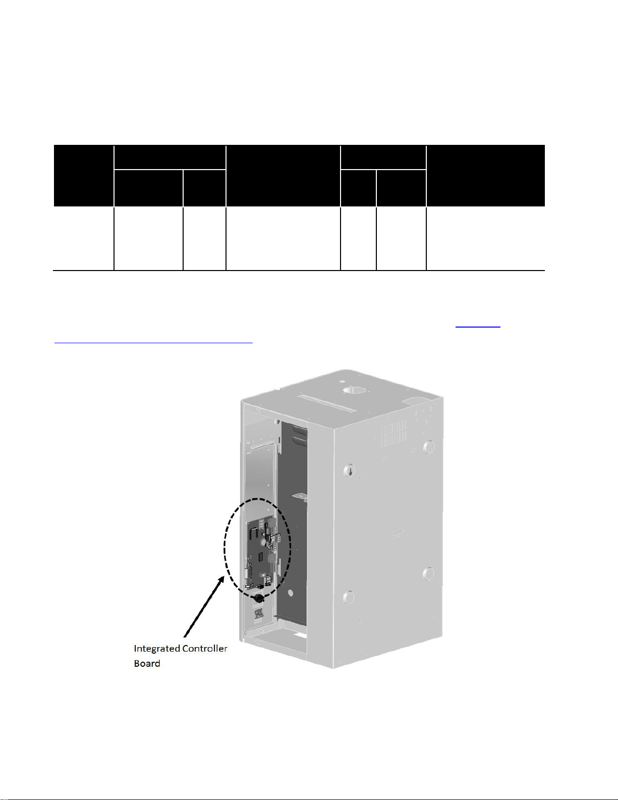
Wiring connections are made directly to the integrated controller circuit board. Figure 1:
Location of Integrated Controller Board shows the location of the board inside the NH-EL.
Figure 1: Location of Integrated Controller Board
BACnet & LONWORKS Supplemental Install Manual | 4
Page 9
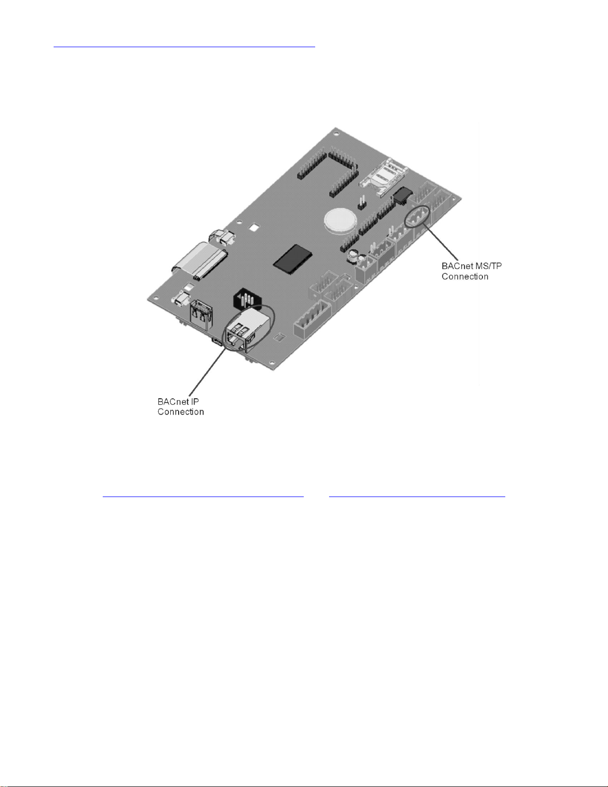
Figure 2: BACnet MS/TP and IP Connection Location show where the physical connections will
be made in order to interface with one of these BMS protocols. For information on Optional
protocols, such as Lonworks or BTL certified BACnet, please see Options (Lonworks, BTL
certified) for details.
Figure 2: BACnet MS/TP and IP Connection Location
Refer to , Figure 3: BACnet MS/TP Wiring Diagram and Figure 4: BACnet IP Wiring Diagram for
instructions on making wiring connections for each respective protocol.
5 | BACnet & LONWORKS Supplemental Install Manual
Page 10
J15
J1
J2J3
J6
J10
J12
J14
J19
J21
J23
J16
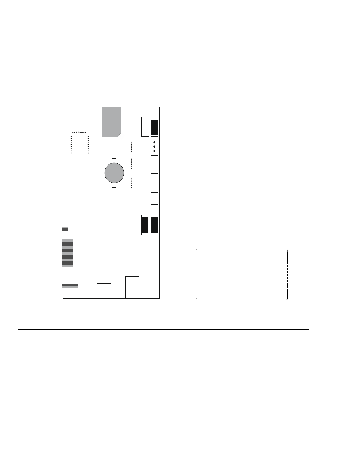
BACnet MS/TP Port
NET
NET
COMMON
(-)
()+
NH-EL BACnet MS/TP Connection
External wiring ‘by others’
RS-485 cable recommended:
-18-24 AWG stranded
-Twisted pair, Shielded
-120 Ohm impedance
-Terminate shield at one end only
Figure 3: BACnet MS/TP Wiring Diagram
BACnet & LONWORKS Supplemental Install Manual | 6
Page 11
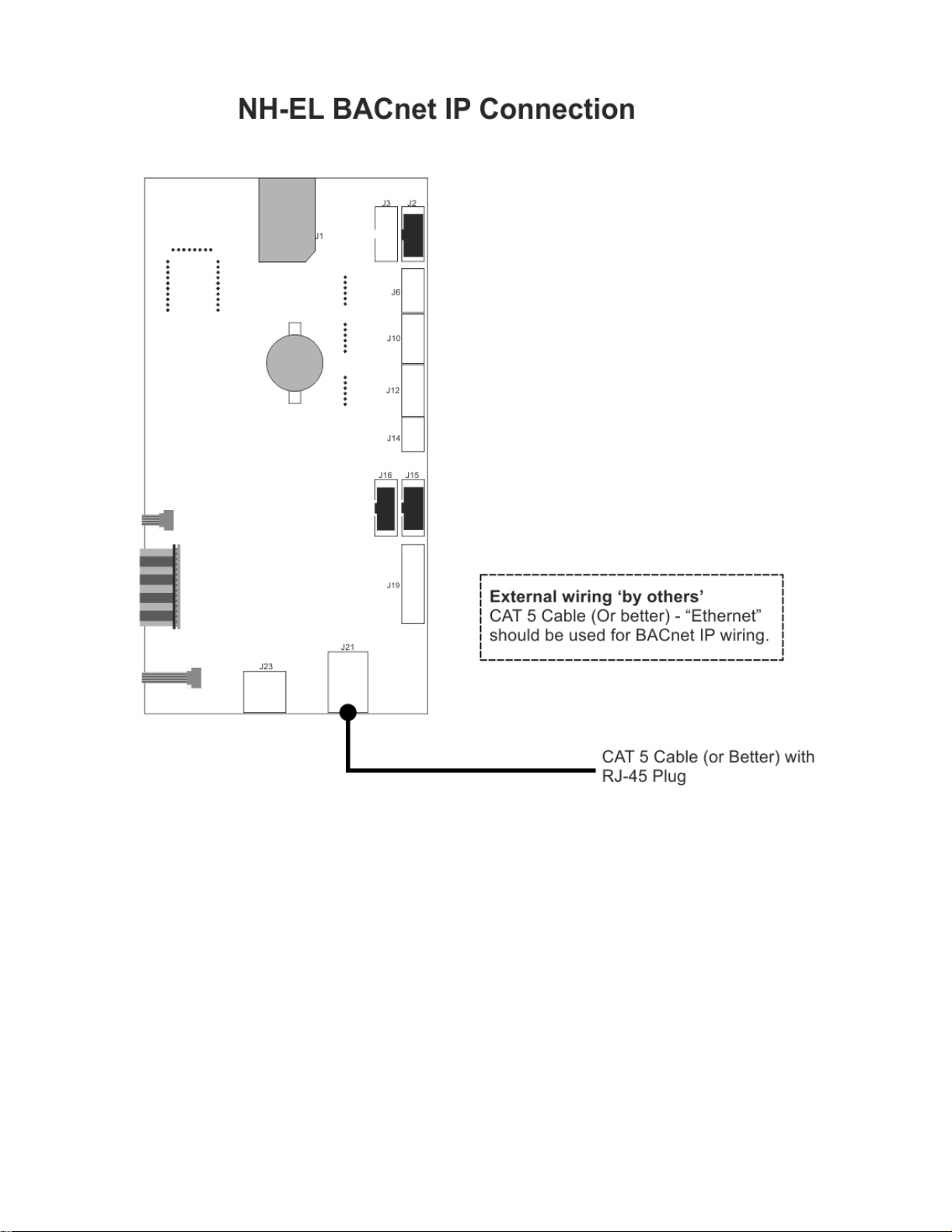
Figure 4: BACnet IP Wiring Diagram
7 | BACnet & LONWORKS Supplemental Install Manual
Page 12

Addressing and Communication
BACnet IP
BACnet MSTP
Default IP addressing
IP Type: DHCP
IP: 192.168.168.243
Subnet: 255.255.255.000
Gateway: 192.168.168.101
N/A
Default BACnet Address
(MAC address)
79
79
Default BACnet Node ID
(Device Instance)
12
1001
After wiring connections have been completed, the humidifier needs to be setup to operate and
communicate through the BACnet interface.
BACnet Communication Set-up
The following table demonstrates the default addressing found on the NH-EL:
Table 3: BACnet Specific Defaults
Locating the IP addressing in the NH-EL is summarized as follows:
Main Menu > 0335 > Configuration > Comms. Menu > Network Parameters >
Note: By default, the NH-EL will have BACnet disabled. To enable BACnet, select BACnet IP or
BACnet MSTP under BACnet Parameters. Select the respective protocol and confirm the
selection by pressing the Check Mark button. This action is summarized as follows:
Main Menu > 0335 > Configuration > Comms. Menu > BACnet Parameters >
Once BACnet is enabled, addressing can be modified as desired.
Locating the BACnet Address (MAC address) in the NH-EL is summarized as follows:
Main Menu > 0335 > Configuration > Comms. Menu > BACnet Parameters > BACnet MSTP
address
Locating the BACnet Node ID (Device Instance) in the NH-EL is summarized as follows:
Main Menu > 0335 > Configuration > Comms. Menu > BACnet Parameters > Node ID
BACnet & LONWORKS Supplemental Install Manual | 8
Page 13

Control Signal Setting
Source
Analog: Use hardwired control signal
BACnet/IP: Write control signal through BACnet/IP interface
BACnet/MS: Write control signal through BACnet/MS interface
Control Mode
Demand: Use a demand control signal
RH P: Use a sensor value and proportional
RH PI: Use a sensor value and proportional-integral control band
Control Channels
Single: Use a single channel control signal
Dual: Use a dual channel control signal
By default the humidifier is configured to operate on a hardwired control signal supplied through
the unit terminal strip. This can be changed to allow the humidifier to function entirely through
its BACnet interface.
*Note: the Humidifier Security loop will still need to be enabled for humidifier to run.
To adjust this setting:
1 Press the Menu icon on the lower left corner of the status screen, to access the menu.
2 When prompted for a password, enter 0335 using the number pad. Press the Check Mark
icon to confirm.
3 Select the Configuration menu.
4 Select the Control Settings menu. The following settings can be adjusted:
Table 4: Control Signal Parameters
Note: Refer to the CONTROL SETTING section of the NH-EL Installation and Operation Manual
for more information on the above settings.
5 Press Back repeatedly to return to the home screen when complete.
This procedure is summarized below:
Main Menu > 0335 > Configuration > Control Settings >
Source: Analog, BACnet/IP, BACnet/MS,
Control Mode: Demand, RH P, or RH PI
Control Channels: Single or Dual
9 | BACnet & LONWORKS Supplemental Install Manual
Page 14

Control Mapping
Parameter
Name
Description
BACnet
ID
Format
Range
Unit
R/W
Details
Dinput_A1
Write RH or
Demand signal
value to control
channel 1 for
cylinder A
10044
Integer
0 - 100
%
Write
Requires BACnet to be enabled.
For most common configurations,
this is the primary control signal
Dinput_A2
Write RH or
Demand signal
value to control
channel 2 for
cylinder A
10045
Integer
0 - 100
%
Write
Requires BACnet to be enabled.
Dinput_B1
Write RH or
Demand signal
value to control
channel 1 for
cylinder B
10046
Integer
0 - 100
%
Write
Requires BACnet to be enabled.
Only applies to NH-EL-150 and
NH-EL-200 with dual channel
control enabled
Dinput_B2
Write RH or
Demand signal
value to control
channel 2 for
cylinder B
10047
Integer
0 - 100
%
Write
Requires BACnet to be enabled.
Only applies to NH-EL-150 and
NH-EL-200 with cylinders dual
channel control enabled and
cylinders in independent
operation mode
Manual_
Capcity_A
Sets a manual
capacity limit
restriction for
cylinder A
10008
Integer
0 - 100
%
Write
Limits output to percentage of
total cylinder capacity (for single
cylinder) or for cylinder A (NH-EL150 and NH-EL-200 models only)
Manual_
Capcity_B
Sets a manual
capacity limit
restriction for
cylinder B (if
present)
10027
Integer
0 - 100
%
Write
Limits output to percentage
capacity for cylinder B (NH-EL150 and NH-EL-200 models only)
BMS_
Timeout
BMS timeout
for Modbus and
BACnet
10043
Integer
0 - 300
s
Write
It is recommend to not change
the value from the factory default
(300)
Remote_
Disable
Remotely
disable steam
production for
the unit
25
Integer
0 or 1
-
Write
0 = Idle/Humidify
1 = Disabled
SP_Chan_
A1
Writes the
desired space
setpoint for
control channel
1 for cylinder A
10010
Integer
0 - 95
%
Write
Use only when Control Mode (14)
is set to RHp or RHpi
Use only when sending RH values
to Dinput_A1.
For most common configurations
this is the primary space
setpoint.
Table 5: BACnet Object Definition List
BACnet & LONWORKS Supplemental Install Manual | 10
Page 15

SP_Chan_
A2
Writes the
desired space
setpoint for
control channel
2 for cylinder A
10013
Integer
10 - 95
%
Write
Use only when sending RH value
to Dinput_A2 with dual channel
control enabled
SP_Chan_
B1
Writes the
desired space
setpoint for
control channel
1 for cylinder B
10016
Integer
0 - 95
%
Write
Use only with NH-EL-150 and NHEL-200 models when sending RH
value to Dinput_B1 and cylinders
are in independent operation
mode
SP_Chan_
B2
Writes the
desired space
setpoint for
control channel
2 for cylinder B
10019
Integer
10 - 95
%
Write
Use only with NH-EL-150 and NHEL-200 models when sending RH
value to Dinput_B2 with dual
channel control enabled and
cylinders are in independent
operation mode
Signal_
Source
Selects signal
source to
control unit
13
Integer
0 - 4
-
Write
0 = Analog
1 = Modbus
2 = BACnet/IP
3 = BACnet/MS
4 = LonWorks
Control_M
ode
Selects method
to control unit
14
Integer
1 - 3
-
Write
1 = Demand
2 = RH P
3 = RH PI
Control_
Channel
Selects method
to control
channels
15
Integer
0 - 1
-
Write
0 = Single Channel
1 = Dual Channel
Input_A1
Displays
channel 1
demand for
cylinder A
10001
Integer
0 - 100
%
Read
Displays channel 1
demand/sensed RH as a
percentage of cylinder capacity
for cylinder A
Input_A2
Displays
channel 2
demand for
cylinder A
10002
Integer
0 - 100
%
Read
Displays channel 2
demand/sensed RH as a
percentage of cylinder capacity
for cylinder A
Input_B1
Displays
channel 1
demand for
cylinder B
10003
Integer
0 - 100
%
Read
Displays channel 1
demand/sensed RH as a
percentage of cylinder capacity
for cylinder B (NH-EL-150 and
NH-EL-200 models only)
Input_B2
Displays
channel 2
demand for
cylinder B
10004
Integer
0 - 100
%
Read
Displays channel 2
demand/sensed RH as a
percentage of cylinder capacity
for cylinder B (NH-EL-150 and
NH-EL-200 models only)
Blower_
Pack_A
Reads the
status of the
blower pack for
cylinder A
4
Integer
0 or 1
-
Read
0 = Open
1 = Closed
11 | BACnet & LONWORKS Supplemental Install Manual
Page 16

Blower_
Pack_B
Reads the
status of the
blower pack for
cylinder B
6
Integer
0 or 1
-
Read
0 = Open
1 = Closed
Fan_
Activate_A
Indicates if air
handle or
furnace is
activated for
cylinder A
1
Integer
0 or 1
-
Read
0 = Not Activated
1 = Activated
Fan_
Activate_B
Indicates if air
handle or
furnace is
activated for
cylinder B
2
Integer
0 or 1
-
Read
0 = Not Activated
1 = Activated
Do_Fault_
A
Reads the
status of a fault
on the unit
69
Integer
0 or 1
-
Read
0 = No Fault
1 = Fault
Do_
Service_A
Reads the
status of a
service request
on the unit
67
Integer
0 or 1
-
Read
0 = No Service Required
1 = Service Required
Humidifier
_
Status_A
Reads the
status of the
unit for cylinder
A
36
Integer
0 - 9
-
Read
0 = Humidifying
1 = Idle
2 = Idle Drain
3 = Keepwarm
4 = Filling
5 = Draining
6 = Disabled
7 = Safety Loop
8 = Warning
9 = Fault
10 = blower pack
Humidifier
_
Status_B
Reads the
status of the
unit for cylinder
A
57
Integer
0 - 9
-
Read
0 = Humidifying
1 = Idle
2 = Idle Drain
3 = Keepwarm
4 = Filling
5 = Draining
6 = Disabled
7 = Safety Loop
8 = Warning
9 = Fault
10 = blower pack
BACnet & LONWORKS Supplemental Install Manual | 12
Page 17

System_
Demand_A
Reads the
demand for
cylinder A
10057
Integer
0 –
100
%
Read
Demand Mode:
Summation of Input_A1 and
Input_A2
RH Mode:
PID calculation
System_
Demand_
B
Reads the
demand for
cylinder B
10058
Integer
0 –
100
%
Read
Demand Mode:
Summation of Input_B1 and
Input_B2
RH Mode:
PID calculation
Safety_
Loop_A
Reads the
status of the
safety loop for
cylinder A
3
Integer
0 or 1
-
Read
0 = Open
1 = Closed
Safety_
Loop_B
Reads the
status of the
safety loop for
cylinder B
5
Integer
0 or 1
-
Read
0 = Open
1 = Closed
Run_Time
_A
Reads
operating time
for cylinder A
10060
Integer
0 5000
Hrs
Read
Displays the total time cylinder A
has been running since last reset
Run_Time
_B
Reads
operating time
for cylinder B
10079
Integer
0 5000
Hrs
Read
Displays the total time cylinder B
has been running since last reset
Weighted_
Hours_A
Reads the
weighted time
for cylinder A
10061
Integer
0 5000
Hrs
Read
An equated run time based on
Run_Time_A x
System_Demand_A
Weighted_
Hours_B
Reads the
weighted time
for cylinder B
10080
Integer
0 5000
Hrs
Read
An equated run time based on
Run_Time_B x
System_Demand_B
13 | BACnet & LONWORKS Supplemental Install Manual
Page 18

Part
Number
Kit Name
Kit Description
2574194
Lonworks, NH-EL
Factory installed option for Echelon’s LonWorks
protocol
2574193
BACnet MSTP, BTL Certified, NH-EL
Factory installed option for BTL approved protocol for
BACnet MSTP
2574192
BACnet IP, BTL Certified, NH-EL
Factory installed option for BTL approved protocol for
BACnet IP
Part
Number
Kit Name
Kit Description
2574197
Lonworks, NH-EL , Retrofit
Field install option for Echelon’s LonWorks protocol
2574196
BACnet MSTP, BTL , NH-EL Retrofit
Field install option for BTL approved protocol for BACnet
MSTP
2574195
BACnet IP, BTL, NH-EL Retrofit
Field install option for BTL approved protocol for BACnet
IP
1
Options (Lonworks, BTL Certified BACnet)
Nortec offers additional protocol options that may be purchased if required. Both field and
factory installed versions are available and include Lonworks and BTL® (BACnet Testing Lab)1
certified BACnet. See Table #6 and Table #7 for specific part numbers and details.
Table 6: Optional Factory Installed Part Numbers
Table 7: Optional Field Install Part Numbers
Field Retrofit Installation
The kits consist of a single interface card that is mounted on the rear side of the integrated
controller. Care should be taken with installation the optional unit in the field. Users will need to
install the interface card onto the pins as shown in Figure 5: Mounting Location and Figure 6:
Pin Alignment. Figure 8: BACnet Specific Port and Figure 9: LonWorks Specific Port display the
location of each port for the respective protocol.
BTL is a registered trademark of BACnet International (BI)
BACnet & LONWORKS Supplemental Install Manual | 14
Page 19

Figure 5: Mounting Location
Figure 6: Pin Alignment
15 | BACnet & LONWORKS Supplemental Install Manual
Page 20

Figure 7: Installation complete
Figure 8: BACnet Specific Ports
Figure 9: LonWorks Specific Port
BACnet & LONWORKS Supplemental Install Manual | 16
Page 21

Addressing and Communication
Source
Analog: Use hardwired control signal
Modbus: Write control signal through BTL Certified BACnet Option
LonWorks: Write control signal through LonWorks Option
Control Mode
Demand: Use a demand control signal
RH P: Use a sensor value and proportional
RH PI: Use a sensor value and proportional-integral control band
Control Channels
Single: Use a single channel control signal
Dual: Use a dual channel control signal
After wiring connections have been completed, the humidifier needs to be setup to operate and
communicate through the interface. The initial step is to configure the Control settings to
ensure the humidifier points to the installed option.
Control Signal Setting
By default the humidifier is configured operate on a hardwired control signal supplied through
the unit terminal strip. This can be changed to allow the humidifier to function entirely through
its Optional interface.
To adjust this setting:
1 Press the Menu icon on the lower left corner of the screen, to access the menu.
2 When prompted for a password, enter 0335 using the number pad. Press the Check Mark
icon to confirm.
3 Select the Configuration menu.
4 Select the Control Settings menu. The following settings can be adjusted:
Table 8: BTL / Lonworks Control Signal Parameters
Note: Refer to the CONTROL SETTING section of the NH-EL Installation and Operation Manual
for more information on the above settings.
5 Press Back repeatedly to return to the home screen when complete.
This procedure is summarized below:
Main Menu > 0335 > Configuration > Control Settings >
Source: Analog, Modbus, LonWorks
Control Mode: Demand, RH P, or RH PI
Control Channels: Single or Dual
17 | BACnet & LONWORKS Supplemental Install Manual
Page 22

Controller Set-up
The BACnet BTL or LonWorks options utilize an additional hardware component. Protocol
configuration is completed at the factory, prior to final testing. It may be necessary to configure
the address parameters in the field.
BACnet IP systems will require a static IP address to communicate on the network.
BACnet MS/TP systems require both a device instance and a baud rate to be set.
LonWorks systems automatically detect network address parameters and do not require
configuration.
BTL Certified BACnet specific : Changing Unit Addressing
The BTL Certified BACnet options utilize an additional hardware component for translation. For
address changes in either BACnet MS/TP or BACnet IP, the device instance and BACnet MAC
address can be modified easily using the dip switches shown in Figure 10: Dipswitches on BTL
Certified BACnet.
Figure 10: Dipswitches on BTL Certified BACnet
These switches allow you to set a binary value between 1 and 127 inclusive. The methodology
for converting numbers to binary is presented in Appendix A. To set the device instance to a
value outside of this range, a specific web browser tool may be used to make IP and address
modifications in the field, Contact Nortec Technical Services for further detail.
Take care when adjusting switches to ensure the settings are entered as intended. Common
settings are tabulated in Appendix A. After an address change has been made, the humidifier
must be power cycled for the change to take effect.
BACnet & LONWORKS Supplemental Install Manual | 18
Page 23

Changing Baud Rate (BACnet MSTP Only)
The baud rate for communications can also be changed through the respective dip switches.
By adjusting the settings according to Appendix A, the baud rate can be changed. For best
results it is recommended to set the baud rate to Auto (BACnet MSTP only), 9600, 19200, or
38400. Communication performance varies with building automation system manufacturer
and some experimentation with other baud rates may be required to obtain the best
performance. The Auto setting is currently only supported for BACnet MSTP networks.
BACnet Pics and Bibs
The Protocol Implementation Conformance Statement or “PICS” describes the BACnet
capabilities of a particular BACnet implementation. It is a written document, created by the
manufacturer of a device, which identifies the particular options specified by BACnet that are
implemented in the device.
BACnet Interoperability Building Blocks (BIBBs) describe a list of services a BACnet device
provides. The main areas that the building blocks are concerned with include: data sharing,
trends, schedules, device and system management. BIBBs help specify the interoperability
capabilities of a BACnet device. Please contact the factory to obtain a PICS statement or BIBBs
profile.
LonWorks Variables
LonWorks uses the identical set of variables/points as BACnet. For a detailed list of the
variables, please see Appendix B.
To facilitate the integration of a LonWorks unit within a network, it may be desirable to obtain an
External Interface File (XIF). Files of type .xif are used to convey the resources, specific objects
and data types which a LonWorks device possesses. The .xif file allows a network integrator to
simulate the presence of a networked humidifier even if it is not yet physically connected to the
network. In fact, if the integrator has the .xif files of all network devices, a complete system
could be simulated and configured off-line. Once the configuration is done, the integrator's
software tool can be connected to the actual system and the configuration information can be
downloaded.
The XIF file can be retrieved directly from the Optional Interface Card. A Windows based laptop
and an Ethernet cable (CAT 5 or better) are required for this process. This process requires the
“Remote User Interface” software tool from Fieldserver. It is available by visiting
http://fieldserver.com/techsupport/utility/utility.php and downloading the “Utility” software:
19 | BACnet & LONWORKS Supplemental Install Manual
Page 24

Figure 11: Software Retrieval
Once this software has been installed, use the following procedure:
1. Locate desired humidifier. Ensure unit is powered on and remove the panel on the Front
side of the humidifier. Locate the Integrated Controller Board inside of the unit.
2. Connect one end of the CAT5 cable into the Ethernet port on the Optional Interface Card
directly.
3. Connect other end of CAT5 cable to the Ethernet port on the laptop.
4. Run the “Remote User Interface” utility by double clicking the shortcut on your desktop (or
Start>Programs>Fieldserver Utilities>Remote User Interface)
5. The program should automatically recognize connected humidifier and bring you to the
“Main Menu”. If it does not, contact Nortec Technical Services at the number on the back
cover of this manual.
6. Type “u” for upload.
7. Type “o” for other. (A warning will appear, press any key to continue.)
8. Type “r” for remote.
BACnet & LONWORKS Supplemental Install Manual | 20
Page 25

9. Enter “fserver.xif”’ and hit the ‘enter’ key.
10. Type “u” to initiate upload from the humidifier to the laptop.
11. The .xif file will be saved in the folder “Configuration File Folder” located at
Start>Programs>Fieldserver Utilities>Configuration File Folder.
12. Type ‘q’ twice to exit out of the program
13. Locate file in Configuration File Folder and change name to corresponding humidifier, (ex,
“fserverH1.xif” for Humidifier 1)
14. Repeat this procedure for humidifiers changing the name of the .xif once saved to
correspond with the tag of the appropriate humidifier.
21 | BACnet & LONWORKS Supplemental Install Manual
Page 26

Troubleshooting
Problem
Resolutions
Cannot see/change
set
object/parameter
from BMS
Check control type. Demand type controls use internal algorithms to
generate a signal telling the humidifier to operate at a certain output
percentage. These of controls do not report the detected humidity
level or set point to the humidifier. As a result the set point and
space humidity levels cannot be monitored through the humidifier
when using demand controls.
Sensor ("transducer") type controls report a sensed humidity value to
the humidifier. The set point is configured at the humidifier and the
humidifier uses internal algorithms to determine the output
percentage. Since the humidifier knows both the set point and
humidity level, these values may be monitored through the
humidifier.
Cannot establish
communication.
Check communication parameters. Nortec humidifiers are capable
of BACnet MSTP and IP communication. LonWorks and BTL certified
BACnet based systems require an interface card to translate the
information, See Options for respective part numbers.
Verify Hardware connections from BMS to humidifier as per the
installation chapter.
Confirm that the protocol has been activated in the humidifier
software: main menu>0335>configuration>Comms menu>
BACnet MSTP Specific:
Check baud rate . Modifying bps may be necessary for some BMS
networks.
Ensure BACnet Workstation/BAS can handle BACnet slave devices
Cannot read data
from
object/parameter
Carefully ensure that addresses are mapped correctly. A single
incorrect address may cause loss of communication or faults for an
entire chain of humidifiers.
Check data type, some network controllers default to integer or
binary values depending on variable type.
Only some
objects/parameters
report data.
Check the baud rate being used on the BMS network. Use of faster
baud rates may assist.
Check the polling rate being used. High polling rates can interrupt
responses from the previous poll of data causing incomplete data
transfer. A recommended polling rate is once per minute.
Humidifier will not
respond to set
point/sensor
values/ demand
values written over
BACnet/LonWorks.
Check that humidifier is configured for automation system.
Refer to the "Control Signal Settings" section for your humidifier
model.
If the setting is "Analog" the humidifier will look for a control signal on
the low voltage terminal strip only.
Table 9: General Troubleshooting
BACnet & LONWORKS Supplemental Install Manual | 22
Page 27

Humidifier will not
respond to
hardwired controls.
Check that humidifier is configured for "Analog" control. Refer to the
"Control Signal Settings" section for your humidifier model. If the
setting is "BACnet" or other, the humidifier will look for a control
value to be written over that medium.
Intermittent
Communications
Check wire type and run length. Wire type should be 18 – 24 AWG,
shielded twisted pair wire with 120 ohm characteristic impedance.
Chains should generally not exceed 2000 feet total length.
Look for wire runs in close proximity to equipment generating
significant electrical noise (such as VFD's, medical equipment, X-ray
machinery, servers, etc).
Check that wire shield is terminated at one end only. Terminations
at both ends cause shield to conduct electricity and can generate
noise.
Confirm correct polarity of conductors at each device. This problem
can be the result of Net+ and Net- terminals being crossed.
Check BACnet Device Instance, LonWorks addressing for conflicts
with any device. Each device on the network must have a unique
address. Devices (humidifiers or otherwise) cannot share addresses.
Invalid data
Check BACnet/LonWorks addresses for conflicts. Each device on the
network must have a unique address. Devices (humidifiers or
otherwise) cannot share addresses.
More variables or
additional
information is
required from the
humidifier.
Contact Nortec Technical Services for additional support.
BACnet MSTP:
Cannot pass data to
controller.
Humidifier does not
pass token
Isolate chain and try only Humidifier.
Embedded BACnet MSTP functions as a slave device and cannot be
setup as a Master. Ensure BACnet Workstation/BAS can handle
BACnet slave devices. If not possible, consider the BTL option for
BACnet MSTP if problem persists. BTL option for BACnet MSTP will
function as a Master device.
23 | BACnet & LONWORKS Supplemental Install Manual
Page 28

APPENDIX A
Switch
A8
A7
A6
A5
A4
A3
A2
A1
Setting
Off
On
Off
Off
On
On
On
Off
Binary 0 1 0 0 1 1 1 0
Exponential Meaning
27 x 0
26 x 1
25 x 0
24 x 0
23 x 1
22 x 1
21 x 1
20 x 0
Simplified Meaning
128 x 0
64 x 1
32 x 0
16 x 0
8 x 1
4 x 1
2 x 1
1 x 0
Numerical Meaning
0
64 0 0 8 4 2 0
Result
64 + 8 + 4 + 2 = 78
Value
A8
A7
A6
A5
A4
A3
A2
A1
0 (Auto)*
Off
Off
Off
Off
Off
Off
Off
Off 1 Off
Off
Off
Off
Off
Off
Off
On
10
Off
Off
Off
Off
On
Off
On
Off
25
Off
Off
Off
On
On
Off
Off
On
40
Off
Off
On
Off
On
Off
Off
Off
50
Off
Off
On
On
Off
Off
On
Off
75
Off
On
Off
Off
On
Off
On
On
78
Off
On
Off
Off
On
On
On
Off
100
Off
On
On
Off
Off
Off
On
Off
125
Off
On
On
On
On
On
Off
On
127
Off
On
On
On
On
On
On
On
Table 10: Converting Numbers to Binary
Table 11: Common Settings for Addressing - BTL BACnet MSTP
* Auto uses the value in the configuration file.
BACnet & LONWORKS Supplemental Install Manual | 24
Page 29

Table 12: Common Settings – Baud rate BTL BACnet MS/TP
Setting
B4
B3
B2
B1
Auto*
Off
Off
Off
Off
110
Off
Off
Off
On
300
Off
Off
On
Off
600
Off
Off
On
On
1200
Off
On
Off
Off
2400
Off
On
Off
On
4800
Off
On
On
Off
9600
Off
On
On
On
19200
On
Off
Off
Off
20833
On
Off
Off
On
28800
On
Off
On
Off
38400
On
Off
On
On
57600
On
On
Off
Off
76800
On
On
Off
On
115200
On
On
On
Off
* Auto baud is only supported for BACnet MSTP
25 | BACnet & LONWORKS Supplemental Install Manual
Page 30

APPENDIX B
Parameter Name
Description
SNVT
#
SNVT
Range
NV
Index
R/W
Details
nviDRHDem_A1
Write RH or
Demand signal
value to control
channel 1 for
cylinder A
81
Lev_percent
0 - 100
23
W
Requires LonWorks
to be enabled.
For most common
configurations, this
is the primary
control signal
nviDRHDem_A2
Write RH or
Demand signal
value to control
channel 2 for
cylinder A
81
Lev_percent
0 - 100
24
W
Requires LonWorks
to be enabled.
nviDRHDem_B1
Write RH or
Demand signal
value to control
channel 1 for
cylinder B
81
Lev_percent
0 - 100
33
W
Requires LonWorks
to be enabled.
Only applies to NHEL-150 and NH-EL200 with dual
channel control
enabled
nviDRHDem_B2
Write RH or
Demand signal
value to control
channel 2 for
cylinder B
81
Lev_percent
0 - 100
34
W
Requires LonWorks
to be enabled.
Only applies to NHEL-150 and NH-EL200 with cylinders
dual channel
control enabled and
cylinders in
independent
operation mode
nviManCapacity_A
Sets a manual
capacity limit
restriction for
cylinder A
81
Lev_percent
0 - 100
15
W
Limits output to
percentage of total
cylinder capacity
(for single cylinder)
or for cylinder A
(NH-EL-150 and
NH-EL-200 models
only)
nviManCapacity_B
Sets a manual
capacity limit
restriction for
cylinder B (if
present)
81
Lev_percent
0 - 100
30
W
Limits output to
percentage capacity
for cylinder B (NHEL-150 and NH-EL200 models only)
nviBMStimeout
BMS timeout
for Modbus and
BACnet
107
SNVT_time_
sec
0 - 300
5
W
It is recommend to
not change the
value from the
factory default
(300)
nviDisable
Remotely disable
steam production
for the unit
95
Switch
0 or 1
44
W
0 = Idle/Humidify
1 = Disabled
Table 13: Parameters
BACnet & LONWORKS Supplemental Install Manual | 26
Page 31

nviSetPoint_A1
Writes the desired
space setpoint for
control channel 1
for cylinder A
81
Lev_percent
0 - 95
21
W
Use only when
sending RH values
to Dinput_A1.
Use only when
nviCtrlMode (3) is
set to RHp or RHpi
For most common
configurations this
is the primary space
setpoint
nviSetPoint_A2
Writes the desired
space setpoint for
control channel 2
for cylinder A
81
Lev_percent
10 - 95
22
W
Use only when
sending RH value to
Dinput_A2 with dual
channel control
enabled
nviSetPoint_B1
Writes the desired
space setpoint for
control channel 1
for cylinder B
81
Lev_percent
0 - 95
36
W
Use only with NHEL-150 and NH-EL200 models when
sending RH value to
Dinput_B1 and
cylinders are in
independent
operation mode
nviSetPoint_B2
Writes the desired
space setpoint for
control channel 2
for cylinder B
81
Lev_percent
10 - 95
37
W
Use only with NHEL-150 and NH-EL200 models when
sending RH value to
Dinput_B2 with
dual channel
control enabled and
cylinders are in
independent
operation mode
nviSigSource
Selects signal
source to control
unit
81
Lev_percent
0 - 4
2
W
0 = Analog
1 = Modbus
2 = BACnet/IP
3 = BACnet/MS
4 = LonWorks
nviCtrlMode
Selects method to
control unit
81
Lev_percent
1 - 3
3
W
1 = Demand
2 = RH P
3 = RH PI
nviCtrlChannel
Selects method to
control channels
81
Lev_percent
0 - 1
4
W
0 = Single Channel
1 = Dual Channel
nvoRHDem_A1
Displays channel 1
demand for
cylinder A
81
Lev_percent
0 - 100
12
R
Displays channel 1
demand/sensed RH
as a percentage of
cylinder capacity for
cylinder A
nvoRHDem_A2
Displays channel 2
demand for
cylinder A
81
Lev_percent
0 - 100
13
R
Displays channel 2
demand/sensed RH
as a percentage of
cylinder capacity for
cylinder A
nvoRHDem_B1
Displays channel 1
demand for
cylinder B
81
Lev_percent
0 - 100
27
R
Displays channel 1
demand/sensed RH
as a percentage of
cylinder capacity for
cylinder B (NH-EL150 and NH-EL-200
models only)
27 | BACnet & LONWORKS Supplemental Install Manual
Page 32

nvoRHDem_B2
Displays channel 2
demand for
cylinder B
81
Lev_percent
0 - 100
28
R
Displays channel 2
demand/sensed RH
as a percentage of
cylinder capacity for
cylinder B (NH-EL150 and NH-EL-200
models only)
nvoBlowerAct_A
Reads the status
of the blower pack
for cylinder A
95
Switch
0 or 1
46
R
0 = Open
1 = Closed
nvoBlowerAct_B
Reads the status
of the blower pack
for cylinder B
95
Switch
0 or 1
49
R
0 = Open
1 = Closed
nvoFanAct_A
Indicates if air
handle or furnace
is activated for
cylinder A
95
Switch
0 or 1
47
R
0 = Not Activated
1 = Activated
nvoFanAct_B
Indicates if air
handle or furnace
is activated for
cylinder B
95
Switch
0 or 1
50
R
0 = Not Activated
1 = Activated
nvoFault
Reads the status
of a fault on the
unit
95
Switch
0 or 1
42
R
0 = No Fault
1 = Fault
nvoService
Reads the status
of a service
request on the unit
95
Switch
0 or 1
41
R
0 = No Service
Required
1 = Service
Required
nvoStatusCylA
Reads the status
of the unit for
cylinder A
81
Lev_percent
0 - 9
1
R
0 = Humidifying
1 = Idle
2 = Idle Drain
3 = Keepwarm
4 = Filling
5 = Draining
6 = Disabled
7 = Safety Loop
8 = Warning
9 = Fault
10 = blower pack
nvoStatusCylB
Reads the status
of the unit for
cylinder B
95
Switch
0 - 9
N/A
R
0 = Humidifying
1 = Idle
2 = Idle Drain
3 = Keepwarm
4 = Filling
5 = Draining
6 = Disabled
7 = Safety Loop
8 = Warning
9 = Fault
10 = blower pack
nvoSysDem_A
Reads the demand
for cylinder A
81
Lev_percent
0 –
100
14
R
Demand Mode:
Summation of
Input_A1 and
Input_A2
RH Mode:
PID calculation
BACnet & LONWORKS Supplemental Install Manual | 28
Page 33

nvoSysDem_B
Reads the demand
for cylinder B
81
Lev_percent
0 –
100
29
R
Demand Mode:
Summation of
Input_B1 and
Input_B2
RH Mode:
PID calculation
nvoSecurity_A
Reads the status
of the safety loop
for cylinder A
95
Switch
0 or 1
45
R
0 = Open
1 = Closed
nvoSecurity_B
Reads the status
of the safety loop
for cylinder B
95
Switch
0 or 1
48
R
0 = Open
1 = Closed
nvoHourOpt_A
Reads operating
time for cylinder A
124
SNVT_time_
hour
0 -
5000
10
R
Displays the total
time (hrs) cylinder A
has been running
since last reset
nvoHourOpt_B
Reads operating
time for cylinder B
124
SNVT_time_
hour
0 -
5000
25
R
Displays the total
time (hrs) cylinder B
has been running
since last reset
nvoHourWeight_A
Reads the
weighted time for
cylinder A
124
SNVT_time_
hour
0 -
5000
11
R
An equated run
time (hrs) based on
Run_Time_A x
System_Demand_A
nvoHourWeight_B
Reads the
weighted time for
cylinder B
124
SNVT_time_
hour
0 -
5000
26
R
An equated run
time (hrs) based on
Run_Time_B x
System_Demand_B
29 | BACnet & LONWORKS Supplemental Install Manual
Page 34

Warranty
Nortec Humidity Inc. and/or Nortec Humidity Ltd. (hereinafter collectively referred to as THE
COMPANY), warrant for a period of two years after installation or 30 months from
manufacturer’s ship date, whichever date is earlier, that THE COMPANY’s manufactured and
assembled products, not otherwise expressly warranted (with the exception of the cylinder), are
free from defects in material and workmanship. No warranty is made against corrosion,
deterioration, or suitability of substituted materials used as a result of compliance with
government regulations.
THE COMPANY’s obligations and liabilities under this warranty are limited to furnishing
replacement parts to the customer, F.O.B. THE COMPANY’s factory, providing the defective
part(s) is returned freight prepaid by the customer. Parts used for repairs are warranted for the
balance of the term of the warranty on the original humidifier or 90 days, whichever is longer.
The warranties set forth herein are in lieu of all other warranties expressed or implied by law. No
liability whatsoever shall be attached to THE COMPANY until said products have been paid for in
full and then said liability shall be limited to the original purchase price for the product. Any
further warranty must be in writing, signed by an officer of THE COMPANY.
THE COMPANY’s limited warranty on accessories, not of the companies manufacture, such as
controls, humidistats, pumps, etc. is limited to the warranty of the original equipment
manufacturer from date of original shipment of humidifier.
THE COMPANY makes no warranty and assumes no liability unless the equipment is installed in
strict accordance with a copy of the catalog and installation manual in effect at the date of
purchase and by a contractor approved by THE COMPANY to install such equipment.
THE COMPANY makes no warranty and assumes no liability whatsoever for consequential
damage or damage resulting directly from misapplication, incorrect sizing or lack of proper
maintenance of the equipment.
THE COMPANY makes no warranty and assumes no liability whatsoever for damage resulting
from freezing of the humidifier, supply lines, drain lines, or steam distribution systems.
THE COMPANY retains the right to change the design, specification and performance criteria of
its products without notice or obligation.
BACnet & LONWORKS Supplemental Install Manual | 30
Page 35

Page 36

U.S.A.
826 Proctor Avenue
Ogdensburg, NY 13669
CANADA
2740 Fenton Road
Ottawa, Ontario K1T 3T7
TEL: 1.866.NORTEC1
FAX: 613.822.7964
EMAIL: nortec@humidity.com
WEBSITE: www.humidity.com
 Loading...