

Page 1
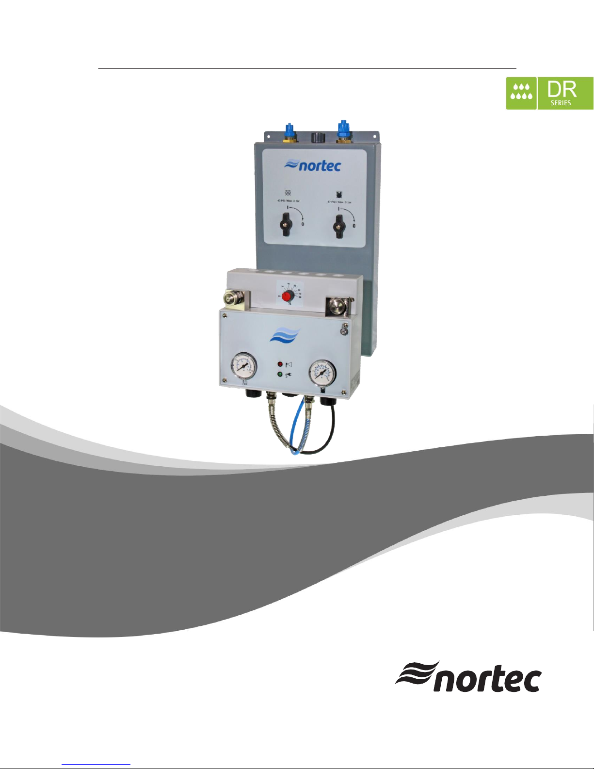
IMPORTANT! Read and save these instructions. This manual to be left with the equipment.
52002_A_EN_1611
INSTALLATION, OPERATION
AND MAINTENANCE MANUAL
Nortec AF-22
Humidification and Evaporative Cooling
Page 2

Thank you for choosing Nortec
Installation date (DD/MM/YYYY):
Commissioning date (DD/MM/YYYY):
Site:
Model:
Serial number:
Nortec Humidity Ltd.
2740 Fenton Road, Ottawa, ON, Canada K1T 3T7
Tel. 1.866.NORTEC1, Fax 613.822.7964
[email protected], www.humidity.com.
Proprietary Notice
This document and the information disclosed herein are proprietary data of Nortec Humidity Ltd. Neither
this document, nor the information contained herein shall be reproduced, used, or disclosed to others
without the written authorization of Nortec Humidity Ltd., except to the extent required for installation,
operation or maintenance of the customer's equipment.
Liability Notice
Nortec Humidity Ltd. does not accept any liability due to incorrect installation, maintenance or operation
of the equipment, or due to the use of parts/components/equipment that are not authorized by Nortec
Humidity Ltd.
Copyright Notice
Copyright 2016, Nortec Humidity Ltd, All rights reserved.
Technical modification rights reserved.
ii 52002_A_EN_1611 Nortec AF-22
Page 3

Contents
1 Introduction 1
1.1 Before You Start! 1
1.2 General 1
2 For Your Safety 3
3 Product Overview 5
3.1 AF-22 5
3.2 AF-22 Functional description 6
4 Basic Principles for Planning 7
4.1 Notes on the planning of air humidification systems in one area 7
4.2 Notes on the planning of an air humidification system in multiple areas 7
4.3 Notes on the water supply 7
4.3.1 Requirements regarding untreated water (drinking water or raw water) 8
4.4 Notes on compressed air supply 9
4.5 Notes on the run of the tubes 9
5 Installation 10
5.1 Safety notes on installation 10
5.2 General notes on positioning 10
5.3 General notes on assembly 10
5.3.1 Standard Mounting 11
5.4 Electrical installation 13
5.4.1 AF-22 13
5.5 Material specifications 15
5.5.1 Protective tube 15
5.5.2 Air tube and water tube 15
5.5.3 Cables 15
6 Operation 16
6.1 Switching off during daily operation 16
6.1.1 Switching off completely 16
6.1.2 Partial switching-off 16
6.2 Setting to operation on a daily basis 17
6.3 Routine checks 17
6.3.1 Atomizer AF-22 17
7 Replacement of Components 18
8 Technical Data 20
9 Appendix 21
9.1 Spare Parts / Options 21
9.2 AF-22 Humidification Load Calculation Examples 21
9.2.1 Example 1 (AF-22) 21
9.2.1.1 Calculating the maximum humidification capacity 22
9.2.1.2 Determining the device requirements 22
9.2.1.3 Determining the compressed air and water requirements 23
9.2.2 Example 2 (AF-22 in multiple areas) 24
9.2.2.1 Calculating the maximum humidification capacity 24
9.2.2.2 Determining the device requirements 25
9.2.2.3 Determining the compressed air and water requirements 26
9.3 Psychometric Chart (Imperial) 27
9.4 Psychometric Chart (Metric) 28
Nortec AF-22 52002_A_EN_1611 iii
Page 4

This page intentionally left blank.
iv 52002_A_EN_1611 Nortec AF-22
Page 5
1 Introduction
CAUTION!
WARNING!
DANGER!
1.1 Before You Start!
Thank you for purchasing the Nortec AF-22 humidifier.
The Nortec AF-22 humidifier incorporates the latest technical advances and meets all recognized safety
standards. Nevertheless, improper use of the Nortec AF-22 humidifier may result in danger to the user or
third parties, and/or damage to property.
To ensure safe, proper and economical operation of the Nortec AF-22 humidifier, observe and comply with
all information and safety instructions contained in this manual, as well as all relevant documentation of
components of the installed humidification system. Comply with all local and regional regulations dealing
with gas, combustion air, flue gases, water, steam and electrical installations.
If you have additional questions, contact your Nortec representative. They will be glad to assist you.
1.2 General
Limitations
The subject of this manual is the Nortec AF-22 humidifier. The various options and accessories may only
be described in-so-far as is necessary for proper installation and operation of the equipment. Additional
information on available options and accessories can be obtained in the instructions that are supplied
with them.
This manual is restricted to the installation of the Nortec AF-22 humidifier, and is intended for well trained
personnel who are suitably qualified for their respective tasks.
Symbols Used in This Manual
The catchword "CAUTION" in conjunction with the general caution symbol is used to provide safety
instructions that, if neglected, may cause damage and/or malfunction of the unit or damage to property.
The catchword "WARNING" in conjunction with the general warning symbol is used to provide safety
instructions that, if neglected, may cause injury to personnel. Other specific warning symbols may also be
used in place of the general symbol.
The catchword "DANGER" in conjunction with the general danger symbol is used to provide safety
instructions that, if neglected, may cause severe injury to personnel or even death. Other specific danger
symbols may also be used in place of the general symbol.
Nortec AF-22 52002_A_EN_1611 1
Page 6

Storage of Manual
Keep this manual in a place where it is safe and readily accessible. If the equipment is moved to another
location, make sure that the manual is passed on to the new user.
If the manual is lost or misplaced, contact your Nortec representative for a replacement copy.
2 52002_A_EN_1611 Nortec AF-22
Page 7
2 For Your Safety
WARNING!
CAUTION!
WARNING!
Agreement on use
The air humidification system is exclusively designed for the controlled humidifying of rooms within the
framework of the specified operating conditions in rooms that are not explosion-endangered. Any other
utilisation is regarded as not contractual and may result in risks caused by the system.
Contractual use also implies serving of all pieces of information contained in this instruction manual
(especially the notes on safety) and strictly paying attention to the operation conditions.
General notes on safety
Only persons who made themselves familiar with the product and who are sufficiently qualified for the
relevant works may install and operate it. Amending the different technical documentation sheets by
means of company-internal directions concerning the responsibility and the obligatory registration, work
organization, qualification of the personnel, etc. lies within the customer’s responsibility.
In accordance with chapter 6, the system has to be switched off before starting works on components of
the air humidification system and is to be secured against unintended putting into operation (switch off
the control device, shut off the water supply and ensure the system is depressurized).
Pay attention to all local safety regulations:
Concerning electric and electronic devices that are supplied from the mains.
Concerning installation of water systems.
Badly maintained air humidification systems may be harmful to health. Therefore it is obligatory to comply
with the intervals of maintenance.
If it is to be assumed that the air humidification system cannot be operated without danger anymore, it
has to be switched off immediately and to be secured against unintended activation. This can be the case
under the following circumstances:
Components of the system are damaged
The system does not work correctly anymore
Connections or pipes are leaking
The air humidification system is to be operated only within the framework of the specified operating
conditions.
The control devices of the air humidification system are only to be operated with 48 VAC safety extra-low
voltages.
Nortec AF-22 52002_A_EN_1611 3
Page 8
Make sure the control devices are secured against drip-water at the place of assembly.
CAUTION!
DANGER!
CAUTION!
When the air humidification system is installed in a room without water drainage, water level sensors that
safely close the water supply (in case of a possible leakage in the water-supply system) have to be
installed in the room.
In order to avoid water damage, do not store any materials that can be damaged by water directly
under the atomizer nozzle.
Danger of corrosion! To avoid dangers, do not store any corrosive components within the area of the
aerosol flow (no rebounding surface for the aerosols).
Depending on the content of minerals in the pipe water or the treated water respectively, scale deposits
that are more or less pronounced can form. Sensitive materials and devices have to be protected
appropriately or to be moved out of this area.
Apart from the works described in this manual, no further interventions have to be carried out on the air
humidification system.
Use only the original accessories and spare parts from Nortec.
Without the written consent of Nortec, no changes may be carried out on the air humidification system.
In case of changes on the system, an approval carried out by Nortec customer service or by persons
authorized by Nortec has to be carried out prior to the first switching on.
4 52002_A_EN_1611 Nortec AF-22
Page 9
3 Product Overview
Designation
Number of nozzles
Max. humidifying capacity
at an atomizing pressure of 5 bar)
AF-22 2 22 lbs/hr (10 l/h)
3.1 AF-22
System description
The system mainly consists of atomization of water supplied into the air. All system components are
integrated into a plastic housing. The atomizing nozzles are assembled firmly onto the upper part of the
housing. In addition, every device is fitted with a hygrostat which measures the relative humidity
(indicated in percent RH - %) in the ambient air. It compares the measured value with the pre-selected
set point and thus controls the device.
Individual smaller rooms or large halls can be humidified, depending on the quantity of water that is
available and the length of the hoses. The atomizers are designed for wall mounting and are delivered
ready for connection.
Table 1: Technical Specification Overview
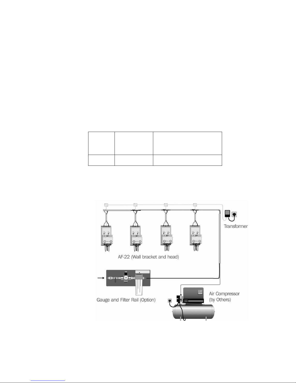
The AF-22 is a two-component atomizer. That means that it needs both water and compressed air for
atomizing.
Figure 1: Typical setup of the system (illustration shows the AF-22)
Nortec AF-22 52002_A_EN_1611 5
Page 10
13
3.2 AF-22 Functional description
The AF-22 is controlled by a hygrostat that is placed in the atomizer head.
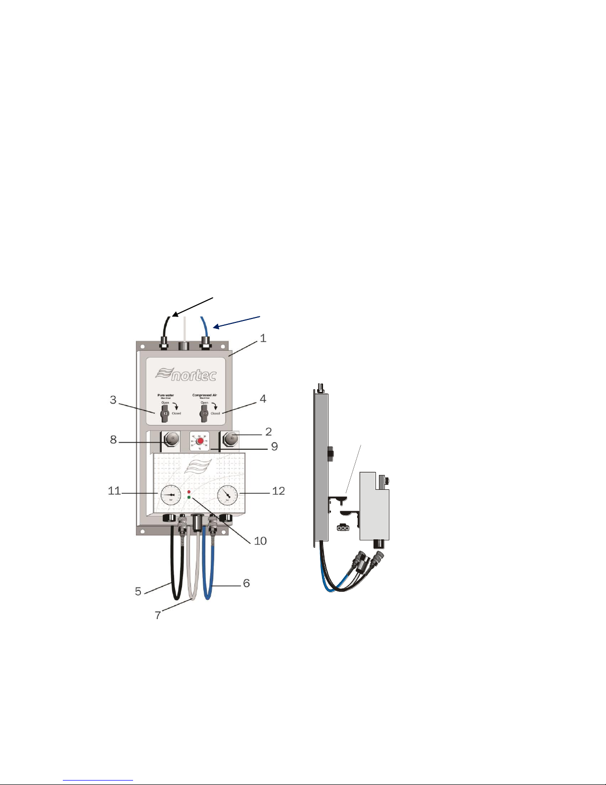
The device consists of two components: the wall bracket (1) and the atomizer (2).
The wall bracket consists of the shut-off valves for water (3) and air (4) as well as the supply lines for water (5), air (6)
and operating voltage (7).
The atomizer consists of the set point adjuster (9), the nozzle (8) as well as the LED indicator lights
standby (green) and atomization (red) (10).
The desired air humidity is pre-selected on the set point adjuster. When the value falls short of the chosen
value, the device switches itself on (LED atomization emits light). When the set point is reached again,
the device switches itself off.
The compressed air supply remains switched on, also after the water was switched off, for about 1 minute
(air-blowing).
The standby indicator lights up as soon as the operating voltage (48 VAC) is available on the device.
Maximum water pressure (inlet) = 43 psi
Maximum air pressure (inlet) = 87 psi
Check the pressure values of the manometers
Water 2.9 – 5.8 psi (11)
Air 43.5 – 58.0 psi (12)
The atomizers can be
adjusted by means of the
ball-and-socket (13) joint.
Figure 2: AF-22 bracket and atomizing system components
6 52002_A_EN_1611 Nortec AF-22
Page 11

4 Basic Principles for Planning
The basic principles for planning described below are theoretical ones. In practice, the necessary
humidification capacity is influenced by parameters that cannot be covered by this documentation. For this
reason, the values that were determined in theory have to be complemented by practical values or corrected in
many cases. Our technical service team will be pleased to assist you.
4.1 Notes on the planning of air humidification systems in one area
Proceed as follows when selecting and/or dimensioning the air humidification system:
Determining the volume of the room and the air changes
Determining the set points (temperature and humidity/relative humidity)
Determining the humidification areas
Calculating the maximum humidification capacity
Defining the device requirements
Chapter 9 (Appendix) contains all necessary pieces of information on the individual planning steps. For
every planning step, a calculation example based on assumed system data has been included. The three
different examples are supposed to illustrate the procedure. Naturally it is not possible to cover all applications by
means of examples. The air humidification system offers a variety of solutions for individual air humidification in a
large variety of rooms.
Nortec distribution and customer service team will be pleased to assist you in case you have any
questions. Telephone: + 1 (262) 884-4669
4.2 Notes on the planning of an air humidification system in multiple areas
In Section 9.2.2 you can see a large room that is, however, divided up into two areas of humidification.
When a room has areas with different heat loads or when the number of air changes is not identical for
the entire room, the atomizers are not able to deliver sufficient measuring results. Certain areas would not
be humidified sufficiently and others would be humidified too much. In these cases and similar cases, the
room can be divided up into two areas of humidification.
4.3 Notes on the water supply
The Nortec AF-22 is a hygienic system and therefore makes particular demands as far as the water to be
atomized is concerned.
The systems can also be operated using untreated source water, but this involves different risks:
Depending on the quality of the untreated water, operating safety may be impaired
Depending on the quality of the untreated water, hygiene may be impaired (depends on the
organic contamination of the untreated water)
Depending on the quality of the untreated water, a very pronounced mineral precipitation may
occur. These substances contained in untreated water precipitate out of the small droplets
(aerosols) and settle on all surfaces. The functioning of processes and machines may be
impaired and more cleaning needs to be done
NOTE:
We recommend you to always use a Nortec water treatment unit in order to achieve optimal results as far
as hygiene and operating safety are concerned.
All requirements regarding water treatment listed below are extremely important in order to ensure a safe,
hygienic operation. The operator shall ensure that the following requirements are met on a permanent
Nortec AF-22 52002_A_EN_1611 7
Page 12
basis. They are fulfilled when a Nortec clean water system is used. The AF-22 also has to be subjected to regular
WARNING!
inspection and preventative maintenance on a regular basis.
Definition of terms:
Untreated water: This kind of water is water to be subjected to water treatment. Also known as
potable water
Soft water: See also 4.3.2. This is water that has been softened
Treated water: This kind of water is a product of water treatment. Another term for treated water is
reverse osmosis treated water (RO water)
Despite compliance with these requirements, contamination of the system cannot be excluded. Regular
checks carried out by the operator are obligatory in order to avoid health hazards.
4.3.1 Requirements regarding untreated water (drinking water or raw water)
The operator shall ensure that the following requirements are met on a permanent basis:
The water must be free of particulates > 5µ
The water has to be free from colloids and/or organic substances as a matter of principle
Well water, rain water and VE water are not admissible
The water must have drinking water quality (e.g. quantity of organic substances)
The maximum number of germs may not exceed 1000 germs/ml
It has to be free from chemical substances/additives (e.g. chlorine, ozone, disinfectants)
No accessory devices that alter the properties of the untreated water (e.g. dosing equipment) may be
used
Water temperature 43-68°F (6-20 °C)
Flow pressure 43-58 psi (2-3 bar)
Requirements regarding water treatment:
A three-stage water treatment system has to be used
Water softening (<0.1 °dH at the outlet)
Filtering (mechanical filter 5 µm + activated-carbon filter)
Demineralization by reverse osmosis (inorganic membrane)
Water values at the outlet of the water treatment system:
o Water hardness < 0.1 °dH
o Conductivity 5-10 µS
o Water temperature 6-25°C (43-77 °F)
o Flow pressure 2-3 bar (43-58 psi)
The product has to be conducted in a closed system up to point where it exits the nozzle and it may not
get in contact with the air in the room any time
No water tanks with float control may be used. Closed membrane tanks made of stainless steel
or plastic have to be used for intermediate storage of the product (pressure control) instead
Fittings and tubes have to be made of materials authorized for the food industry (plastic, stainless
steel). Do not use copper or brass tubes!
The treated water has to be free from organic substances
8 52002_A_EN_1611 Nortec AF-22
Page 13
4.4 Notes on compressed air supply
WARNING!
The operator shall ensure that the following requirements are met on a permanent basis:
The compressed air must have respiratory air quality and be free from contamination
(residual oil content < 0.003 mg/m3, dust, water, etc.)
The admissible inlet pressure on the wall brackets is max. 87 psi (without pressure
fluctuations and pressure blows)
When dimensioning the compressor and/or the outlet pressure, possible losses via the tube
network have to be taken into consideration
It is recommended to install a micro filter and an activated carbon filter
When a manometer and a pressure-relief device are installed in the compressed air feed, the
performance of the system can be assessed more easily.
Important! The compressed air line has to be blown out before it is connected.
4.5 Notes on the run of the tubes
Use a suitable cutting device guaranteeing a straight and kink-free cut when cutting the
tubes
The tubes may not be kinked or damaged (longitudinal grooves)
Make sure that the tubes are not kinked and that a minimum bending radius of 1.57 inches
(40 mm) is maintained
Do not pass the tubes near warm or even hot components (max. admissible ambient
temperature 95°F (35°C))
Avoid exposure of the tube to direct sunlight
In order to protect them against damage and to prevent them from sagging, the tubes have to be run
between the individual components inside a protective tube, if possible.
Upon installation, check:
Whether all tubes sit tight. It is not possible to pull out correctly mounted tubes without
exercising pressure on the clamping ring
The water and compressed air systems for tightness
It is recommended to install the network of tubes in the form of a star, if possible. When the distance
between the air supply and the water supply is too large, malfunctions or even problems regarding
hygiene may occur. Always call Nortec customer service in case of doubt (+1 262 884 4669).
The last atomizer of a series may be at a maximum distance of 230 feet (70 metres) from the air supply
and/or the water supply.
Nortec AF-22 52002_A_EN_1611 9
Page 14

5 Installation
5.1 Safety notes on installation
Assembly and installation may only be carried out by authorized, qualified staff (plumbers, electricians). The
person who places the order for the installation has to ensure that they are qualified accordingly.
All local rules and regulations on the execution of electrical installations and water installations must be complied with.
It is obligatory to read the notes and regulations of this chapter for adequate placement of system components, on
assembly and electrical installations and to comply with them.
5.2 General notes on positioning
The positioning of a system is always determined during planning and noted in the system documents.
The following general positioning notes, however, have to be read and complied with in any case:
Make sure that the construction (wall, pillar, ceiling construction, etc.) on which the devices
and/or system components will be mounted disposes of a sufficient load-carrying capacity
and is suitable for fixing (see Chapter 8. “Technical data“)
Position the atomizers in such a way to enable the aerosol mist to spread freely. When the
aerosol mist is prevented from spreading by obstacles (e.g. ceilings, beams, etc.), turbulences
can build up and condensation may occur as a result
In the illustration shown in the next section, you will find the measurements of the expansion of
the aerosol stream, and the clearances that have to be kept. The measurements relate to
the maximum humidification capacity of the atomizer nozzles and a room temperature between
64°F and 75°F. When the temperature is higher, the expansion of the aerosol stream is reduced, when the
temperature is lower, it increases
When atomizer nozzles are installed one opposite the other, make sure that a minimum distance of 26 ft.
is maintained between the nozzles in order to avoid that the aerosol streams condensate each
other
Pay attention to the airflow of the room. Do not install atomizer nozzles in the immediate vicinity of an
exhaust system or of a cold-air inlet
Do not direct atomizer nozzles at cold parts of a building, e.g. outside walls, windows, etc. (risk of
condensation)
Insulate cold-water pipes in the area of the aerosol stream (risk of condensation)
The evaporation process absorbs heat from the ambient air. For this reason, make sure that the
aerosol stream is not directed on persons or on places directly above workplaces
In order to guarantee an optimum humidification, ensure that the atomizers are sensibly
distributed in the room
The system components have to be mounted in such a way to provide enough space for
operation and maintenance
Please contact Nortec in case you have questions on positioning and clearances.
5.3 General notes on assembly
Installation has to be carried out according to the general engineering rules and the connection
regulations of the local utility companies
Before the installation, check whether the delivery is complete and undamaged, using the delivery notes
for this purpose
The tubes may only be installed by certified master craftsmen that were instructed on how to proceed
No unauthorized conversions or alterations may be carried out on the devices
No additional fittings (e.g. valves, etc.) that are not included in the assembly plan may be installed in
the Nortec system
10 52002_A_EN_1611 Nortec AF-22
Page 15
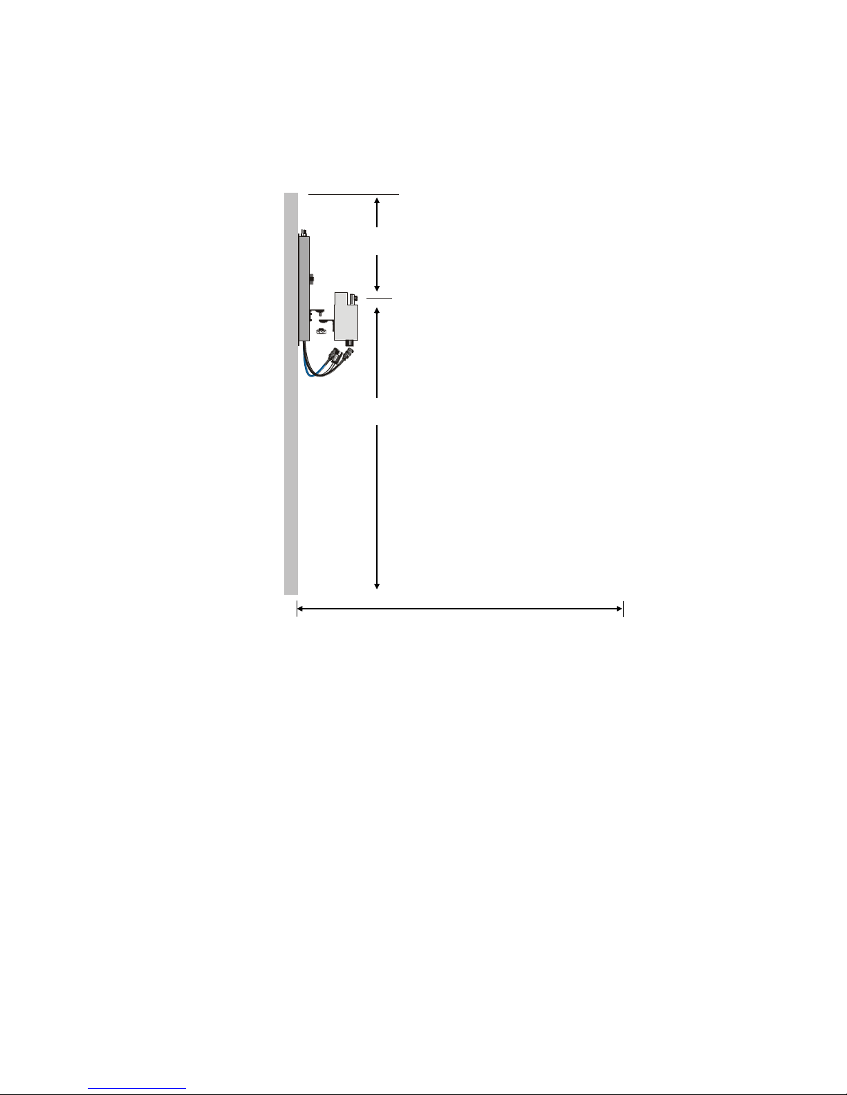
9.84 - 13.0 ft. (3.00 – 3.97 m)
These assembly instructions only refer to individual systems. The manufacturer provides individual
8.20 ft. (2.50 m)
Min. 1.64 ft. (0.50 m)
system diagrams for the customers' systems
It is obligatory to comply with the material specifications
5.3.1 Standard Mounting
Positioning of the atomizers
Select a distance to the ceiling of at least 1.64 ft.
Do not place the atomizers directly above a workplace
The air space has to be free over a distance of 9.84 ft. - 13.0 ft. in an angle of 90°
Avoid exposure of the atomizers to direct sunlight
Connection of the wall bracket
All AF-22 devices are connected with the quick assembly kit delivered as accessory.
The connection for treated water is made using the black PU-4 tube (create branch line to the wall bracket using the
enclosed T connectors).
The compressed air tube is connected using the blue PU-9 tube (create branch line to the wall bracket using
the enclosed T connectors).
The power supply from the transformer is connected via junction boxes in the form of a branch line to the
relevant wall bracket. On the junction box, it is run through the cable duct of the wall bracket and connected to
the enclosed plugs. The length of the cables has to correspond to the length of the tubes.
Figure 5: AF-22 wall mounting
Nortec AF-22 52002_A_EN_1611 11
Page 16
12 52002_A_EN_1611 Nortec AF-22
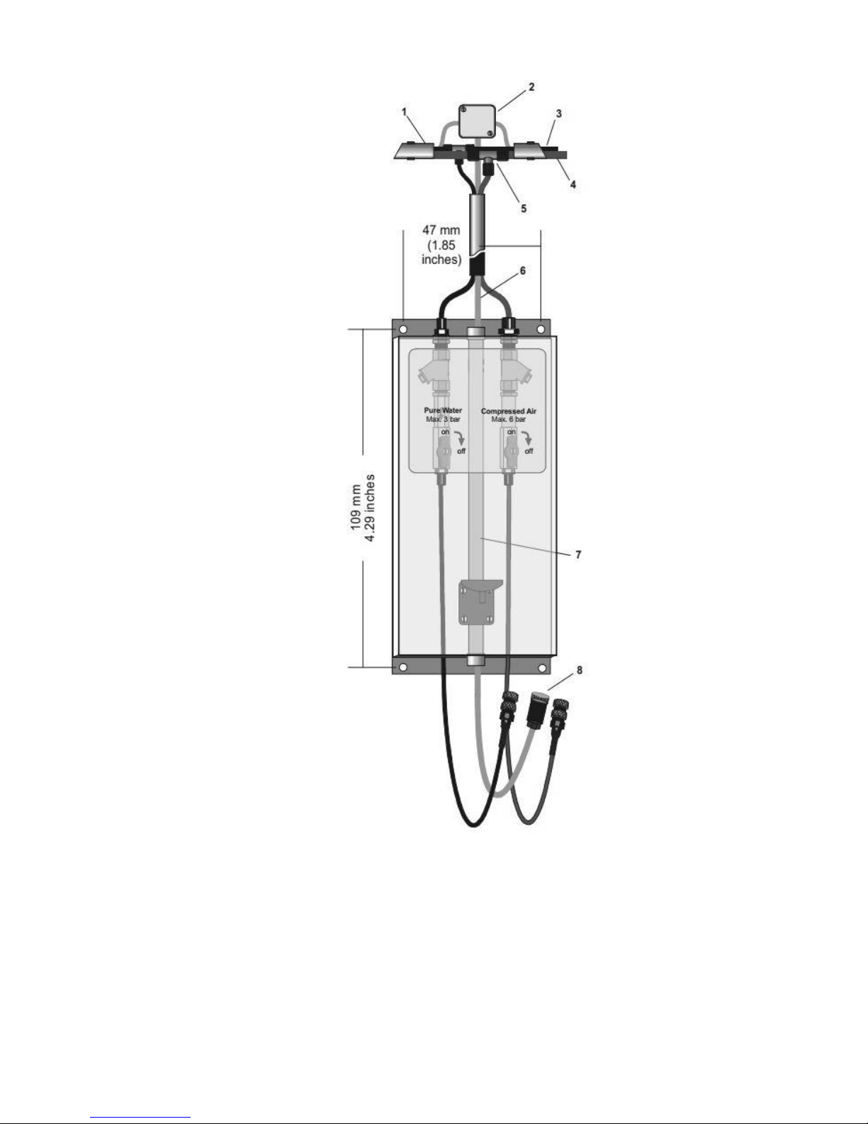
Figure 6: AF-22 Wall Bracket Connection
(1) Protective tube PG 29 (2) Distributing box
(3) Treated water tube PU-4 (4) Compressed air tube PU-9
(5) T connector (6) Cable HO5 VV-F-2 x 1.5
(7) Cable inlet wall bracket (8) Plug
Page 17
5.4 Electrical installation
CAUTION!
CAUTION!
WARNING!
The documentation does not cover the installation of the voltage supply. However, it does include the
electrical requirements.
The layouts of the electrical installation and voltage supply have to comply with the local safety regulations and
standards.
NOTES: Electrical installation:
It is obligatory to run the connecting cables through the cable fittings provided for that purpose in the device.
The atomizers may only be supplied with 48 VAC/50…60 Hz.
5.4.1 AF-22
The voltage supply for the atomizers is provided directly to the wall brackets (with a junction box) via the
external safety transformer.
Before and when working on the devices, make sure that all lines are disconnected and that the voltage
supply is secured against unintentional switching on.
NOTE: The transformer must be positioned as close as possible to the atomizers in order to avoid an
unnecessary loss of voltage on the lines. You can connect a maximum of four (quantity 4) atomizers to
the supplying transformer.
A special plug is included in the scope of delivery of the wall brackets. Only this plug may be used to
connect the atomizers.
Nortec AF-22 52002_A_EN_1611 13
Page 18
TRAFO
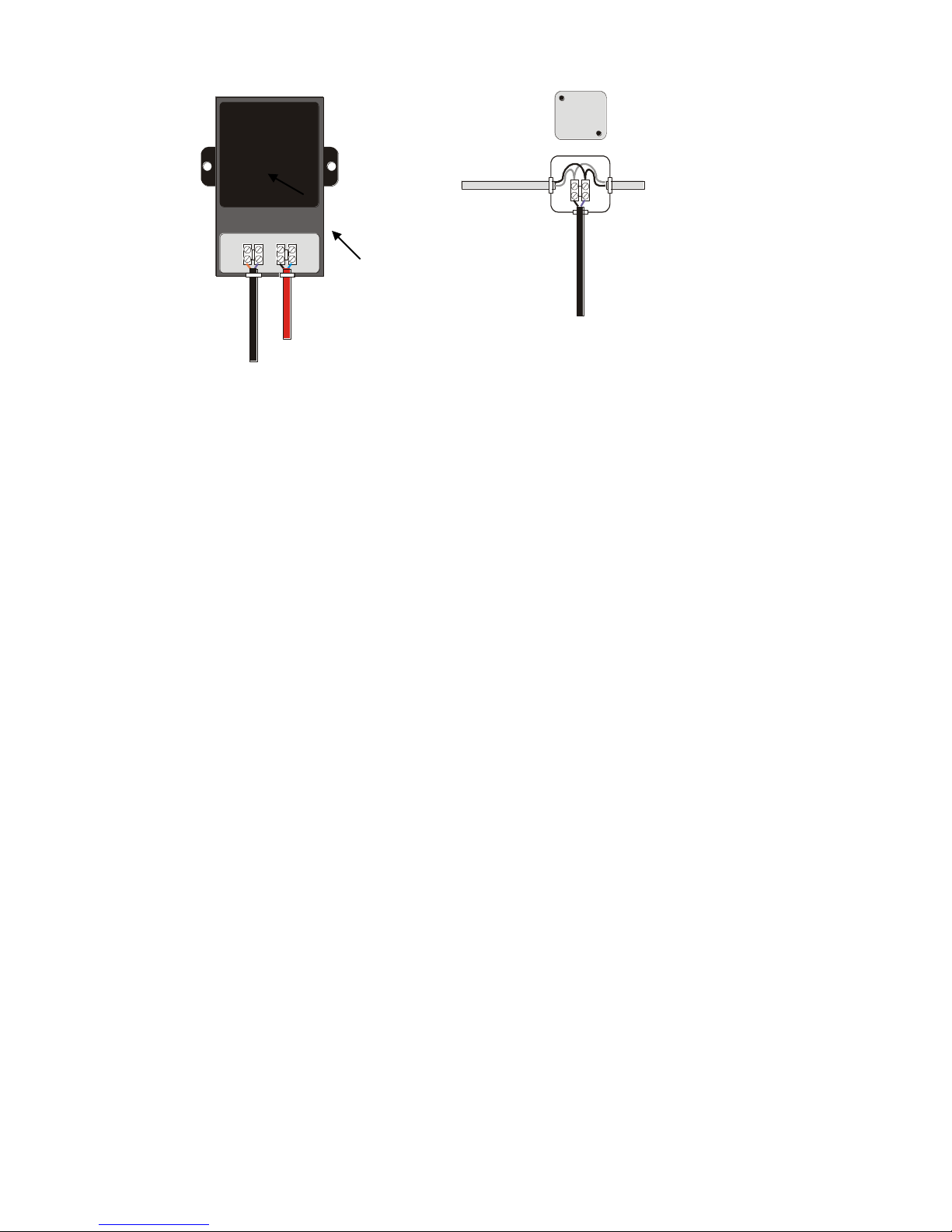
AF-22: from the transformer to the next atomizer
2 x 2.5 mm² 2 x 2.5 mm²
Fuse 2,0A
115VAC, 50-60 Hz 48VACV, 50-60 Hz 2 x 1.5 mm²
1 phase, zero two wires to the wall bracket (plug)
2 x 2.5 mm² 2 x 2.5 mm²
Fusing: 10A to the group control device or the first atomizer
Figure 7: Electrical installation to transformer
Plug connection:
Litz wire, black, sw PIN3
Litz wire, blue, bl PIN PE
14 52002_A_EN_1611 Nortec AF-22
Page 19

5.5 Material specification
5.5.1 Protective tube
Insulating material tube (protective tube)
PG 16/PG 29
Material: PVC-U
Complies with: DIN 49016, Part 2, DIN 16929, DIN 4102
Temperature Range: 23°F - 140°F
Quick clamps
Material: Polypropylene
Temperature Range: -22°F - 194°F
Suitable for protective tube and for wall mounting.
5.5.2 Air tube and water tube
PU 4 tube, black (water side)
Material: Polyurethane
6 x 4 x 1 mm
Max. operating pressure: 145 psi at 68°F
PU 9 tube, blue (air side)
Material: Polyurethane
12 x 9 x 1.5 mm
Max. Operating pressure: 101 psi at 68°F
Plastic coupling pieces
Material: POM
Pressure range: 0 - 10 bar
Temp. range: 14°F - 140°F
Suitable for PU tube, black and blue.
5.5.3 Cables
Type 1
Use: Voltage supply from domestic mains to external transformer
Description: H05 W-F 2 x 1.5 mm²
Fusing (domestic mains): 10A, slow-to-blow
Type 2
Use: From external transformer to atomizers and/or group control unit.
From group control unit to atomizers, in addition.
Description: H05 W-F 2 x 2.5 mm
Fusing (in transformer): 2.5A, slow-to-blow
²
Nortec AF-22 52002_A_EN_1611 15
Page 20
6 Operation
WARNING!
WARNING!
WARNING!
The Nortec AF-22 humidifier must only be operated by personnel who are adequately qualified, well
trained and are authorized by the customer.
6.1 Switching-off during daily operation
For maintenance, the replacement of defective, faulty system components or required, it may be
necessary to take the system out of operation. More information on when to disconnect the system is
included in Chapter 7 (see also the replacement instructions for the individual components).
When switching off the system, always ensure a thorough and complete disconnection and draining of
the system (water supply and voltage supply, depending on the type of disconnection). The employees
have to be informed about the disconnection.
6.1.1 Switching-off completely
The humidification system can be partially or completely disconnected, and the water supply is switched
off.
Atomizer AF-22:
Remove the voltage supply plug from the device. The water supply and/or the compressed air supply can
also be interrupted in addition by removing the quick couplings.
Please note that there is a risk of stagnant water contamination when it is switched off for a longer time
period, more than 24 hours (fresh water automatic system not active). It is obligatory to inform Nortec
customer service before switching the system off completely.
6.1.2 Partial switching-off
Adjust the set-point to 20% RH. In this case, the fresh water automatic system is still active.
You can also disconnect the water supply and/or compressed air supply of the atomizers by removing the
quick couplings in order to stop the device from working. This may only be done in an emergency.
Please note that there is a risk of stagnant water contamination when it is switched off for a longer time
period (more than 24 hours) (fresh water automatic system not active).
16 52002_A_EN_1611 Nortec AF-22
Page 21
6.2 Setting to operation on a daily basis
1 2 3
CAUTION!
CAUTION!
Depending on whether a partial or complete switching-off was performed, switching-on has to be
performed in reverse order (see also the replacement instructions for the individual devices).
First connect the water supply and/or the compressed air supply (quick couplings). Then connect the voltage
supply (plug). Now you can adjust the set-point to the desired value again on the AF-22.
6.3 Routine checks
When irregularities or malfunctions are detected during checks, inform Nortec customer service at once.
Routine checks may only be carried out by authorized staff. The operator is responsible for checking the
suitability of the staff and for instructing them.
6.3.1 Atomizer AF-22
Assess the spray pattern. The ratio water consumption/compressed air consumption has a considerable influence
on the spray pattern. These parameters can be set on the device. Work settings may never be changed
without prior consultation of Nortec customer service.
Cycle: Every 2 weeks
The routine check is necessary because it is possible to prevent damage when a very bad atomization
process is detected in time. The worse the atomizing result, the bigger the drops. Drops falling down may
cause damage by corrosion.
In areas with a lot of dust and/or dirt formation, the functioning of the atomizers may be impaired. Check this and
remove the dirt, if necessary. Deposits on the nozzles may impair the spray pattern. You can try to clean them
as follows as an emergency measure:
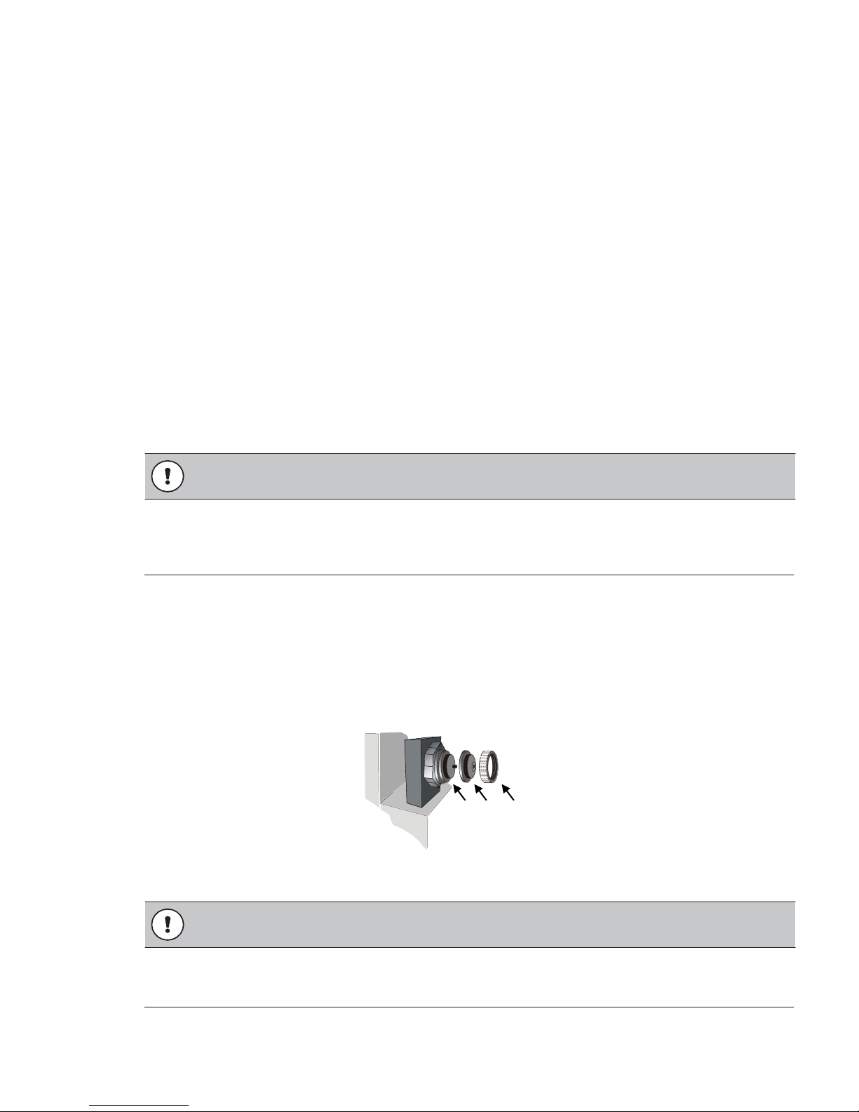
Disconnect the device and switch off the valves for air and water. Remove the knurled thumb screw (3) and the
air cap. Remove deposits at the tip of the nozzle (1) using a soft, lint-free cloth. Never use a needle or similar
solid objects for cleaning!
Figure 8: Atomization checks and nozzle cleaning
Cycle: Every 4 weeks
Do not clean with water or any kind of cleaners, but only vacuum it. Disconnect the device and protect
against switching on before cleaning.
Nortec AF-22 52002_A_EN_1611 17
Page 22
7 Replacement of components
CAUTION!
Please inform Nortec customer service when you notice a malfunction on the system.
Nortec Humidity Ltd
Spare Parts (Mon. – Fri.) Phone: +1 262 884 4669
8:00 a.m. – 5:00 p.m.
Customer Service (Mon. – Fri.) Phone: +1 866 667 8321
8:30 a.m. – 4:30 p.m.
The replacement is to be made only by instructed, trained personnel. The operator is obliged to ensure
that the personnel is suited, has been instructed and trained as required. He is obligated to comply with the
instructions of Nortec in the process, especially the instructions contained in this documentation.
Please inform the people working nearby, that work will be carried out on the air humidification system.
Make sure that the system cannot be switched on unintentionally.
18 52002_A_EN_1611 Nortec AF-22
Page 23
Atomizer AF-22 component replacement
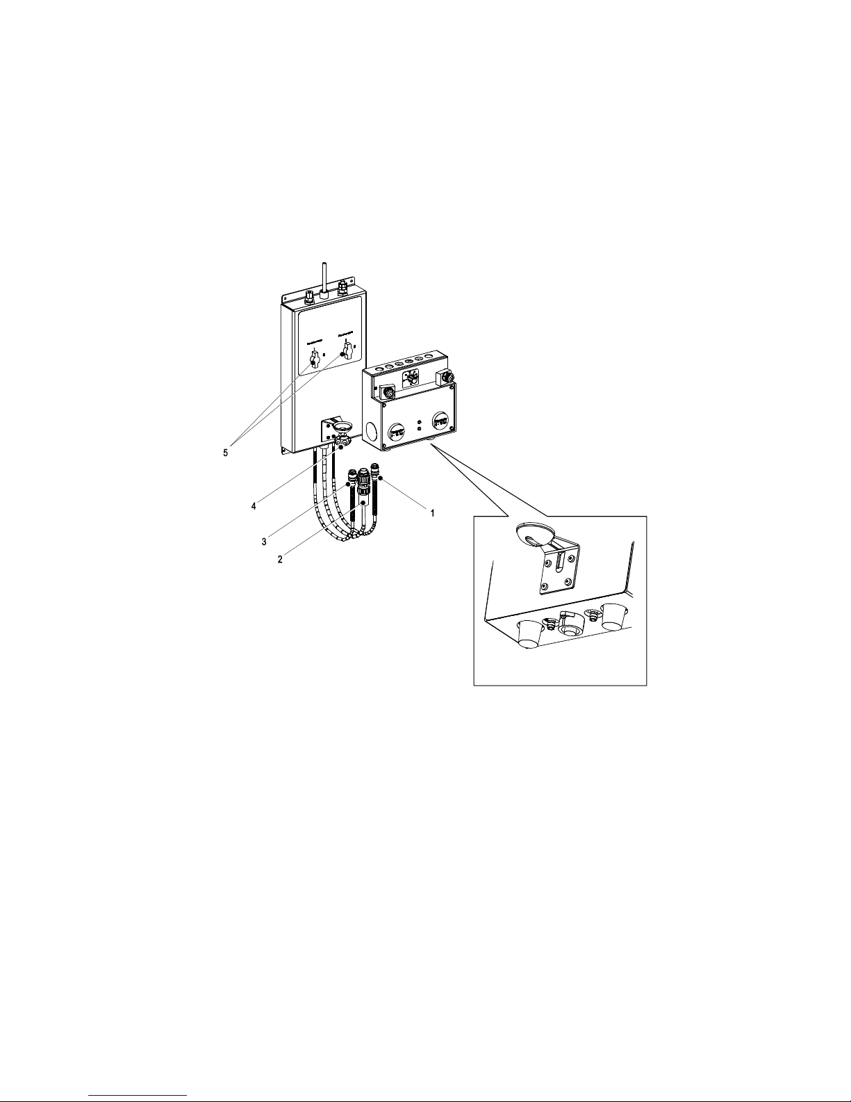
1. Close the shut-off valves (5) on the wall bracket.
2. Pull off the plug couplings (3) and (1) for compressed air and water. Press down the knurled ring and
then pull out the plug couplings downwards in order to do that.
3. Pull off the plug (2). Loosen the knurled ring on the plug by turning it anti-clockwise and pull out the
plug downwards.
4. Remove the atomizer by unscrewing the star knob screw (4) and attach the new atomizer.
5. Connect the new atomizer in reverse order (Do not connect the supplying lines crosswise!). Adjust
the desired set point, (for example 50% RH) on the hygrostat. Adjust the atomizer by means of the
star knob screw (4).
Figure 9: AF-22 bracket connection to atomizer box
Nortec AF-22 52002_A_EN_1611 19
Page 24

8 Technical Data
Specification data
Capacity
22 lbs/hr (10 kg/hr)*
Compressed air requirements
60 Nlm
Working pressure air / water
43.5-58.0 psi/2.9-5.9 psi*1
Dimensions (w x h x d)
8.26 in x 21.75 in x 9.84 in
Weight
6.1 lbs (2.8 kg)
Operating voltage
48 VAC, 50 Hz, ±10%
Power input
20 W
Overvoltage category
II
Pollution degree
2
Application
Inside only
Height above sea level
6,670 ft. (2,000 m)
Ambient temperature
44-95 °F (7-35°C)
Ambient humidity
Max. 80 %, prevent condensation
Table 2: AF-22 Technical Specifications
*: Depending on the set water / air ratio
*1: factory settings
20 52002_A_EN_1611 Nortec AF-22
Page 25
9 Appendix
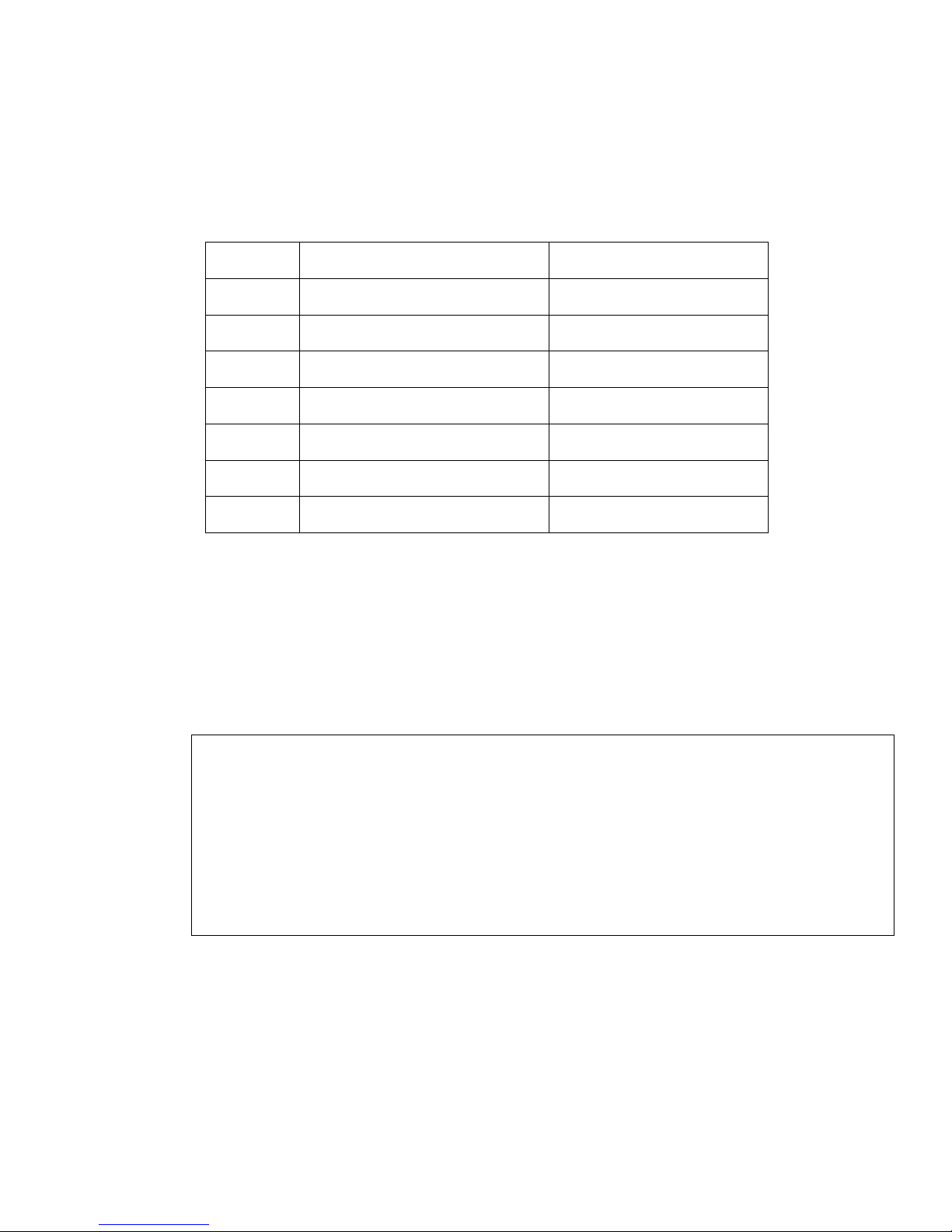
Part Number
Part Name
Description
2523539
Wall mounted Gauge & Filter Rail
Water filter
2577587
LPES 1000 RO System
Reverse osmosis system
2300194
62 Gallon Repo. Tank
Reverse osmosis water holding tank
52003
AF-22 Pure Water Atomizer (Head)
Main head with atomization nozzles
9558
Biosafe transformer
AF-22 spare or extra 48V transformer
25005
Low Pressure Hose (air) – PU 9 Blue
Compressed air extra hose
25004
Low Pressure Hose (water) – PU 4 Black
Water supply extra hose
9.1 Spare Parts / Options
Table 3: Spare Parts List
9.2 AF-22 Humidification Load Calculation Examples
9.2.1 Example 1 (AF-22)
In this case, only one room is to be humidified. As every atomizer is fitted with its own hygrostat, different zones
within one area (room) can be humidified individually.
EXAMPLE 1
A Nortec AF-22 for direct room air humidification is to be installed in the paper store of a large printing
works. The following data is available:
Room measurements (l x w x h) in ft.: 98.0 x 66.0 x 11.5
Number of air changes per hour: 2.2
Outside air conditions in winter: 5°F/ 90 % RH
Desired room temperature: 70°F
Desired relative air humidity: 53 % RH
Areas: One
Nortec AF-22 52002_A_EN_1611 21
Page 26
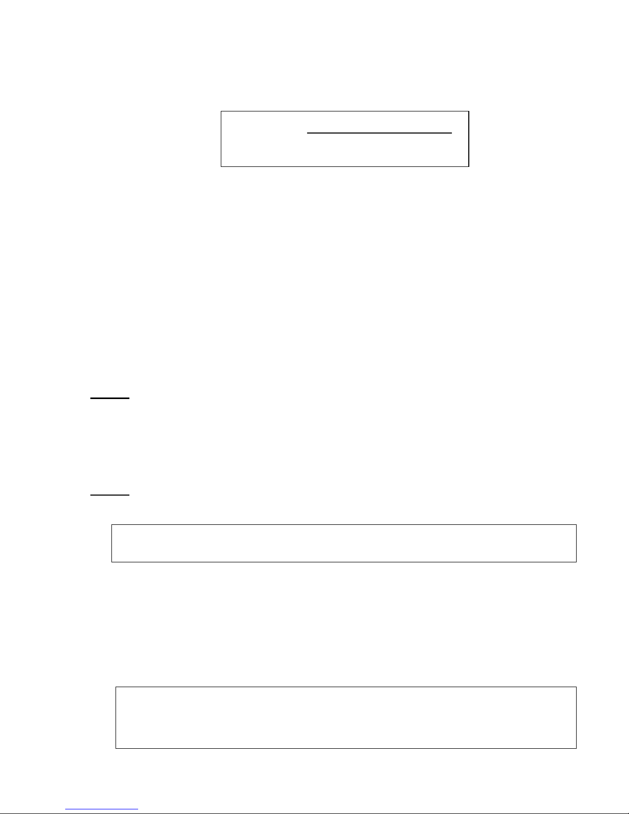
9.2.1.1 Calculating the maximum humidification capacity
V x 1.0 x AE/h x (X2 – X1)
m
H2O
=
A x V1
The maximum humidification capacity is calculated using the following formula:
m
: Maximum humidification capacity in lb/h
H2O
V : Air volume to be humidified in ft³ (formula: L x W x H)
V1 : Specific volume of air at set point in ft³/lb
AE/h : Number of air changes per hour
The number of air changes per hour depends on the usage of the room and must be determined by the system
planner as part of the planning process. The following guide values can be taken as the basis:
Textile processing: 3 – 7 AE/h
Printing works: 2 – 5 AE/h
Storerooms: 1 – 3 AE/h
Cooling rooms: max. 1 AE/h
1.0 : Fixed value for the specific weight of the air in lb/ft³
A : Fixed value (7,000) for the conversion of pounds to grains in grains/lb.
x2 : Desired absolute humidity of the air in the room in grains/lb
x1 : Minimum absolute humidity y before humidification in grains/lb
NOTES:
Where outside air represents 100 % of the air, the outside air condition in winter must be applied. If there is an air
circulation system (30 % outside air, 70 % recirculated air), the resulting air mix must be applied.
For the values for x2 and x1 refer to the psychrometric chart in the appendix.
NOTES:
The formula takes no account any absorption or discharge of humidity by materials in the humidified room.
SOLUTION EXAMPLE 1
In this example, a humidification capacity of 101 lbs/h is required.
In case of questions regarding the calculation of the humidification capacity, please contact Nortec.
9.2.1.2 Determining the device requirements
Now the decisive value of the necessary humidification capacity is available for the determination. The
following notes on the capacity of the atomizers provide a second basis.
Capacity AF-22 (22 lbs/h)
EXAMPLE 1 (continued)
Total water volume (mH2O) = 101 lbs/h
Required:
5 units AF-22
1 unit transformer
22 52002_A_EN_1611 Nortec AF-22
Page 27
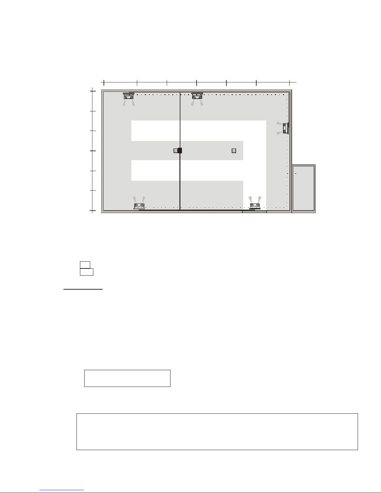
The tube requirements for air supply and power supply depend on the cable. They are determined on the
10
15
20
20
30
WA
KOM
Trafo
basis of the ground plan. The result for this example is approx. 230 ft. of Nortec quick assembly kit
(SMB). The SMB comes with the necessary cables, low-pressure tubes and fittings. For further notes on
the tube run, please see Chapter 4.3-4.5.
Figure 10: Example 1 schematic
The solid line stands for power supply, the dotted line for air and water supply. Dimension scale is shown in metres.
WA : Water treatment (if necessary)
KOM : Compressor
IMPORTANT: Make sure to connect no more than six (6) AF-22 to one string when planning the
supply network for the atomizers (water and compressed air). Malfunctions may occur if more than six (6)
devices are connected. To avoid malfunction - two further strings must be created for splitting up the
string (see sketch above).
9.2.1.3 Determining the compressed air and water requirements
Compressed air requirements
The compressed-air consumption of a system depends on the number of atomizers and is calculated using the
following formula:
QL = nD x 60Nl/min
QL: Necessary air volume in Nl/min
nD: Number of devices
Related to the example and using the following values:
nD = 5
The result is an air volume of 300 l/min.
Nortec AF-22 52002_A_EN_1611 23
Page 28
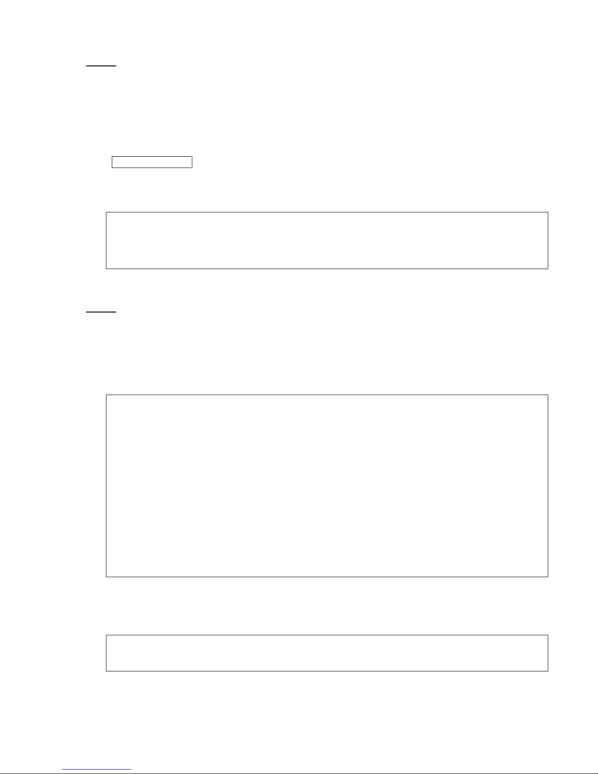
NOTE:
In order to ensure a trouble-free operation, the compressed-air system must deliver 1.2 times the air
volume that has been calculated.
Water requirements
The water requirements of a system depend on the number of atomizers and are calculated using the
following formula:
QW = nD x 22lbs/hr
QW: Necessary water in lbs/h
nD: Number of devices
Related to the example and using the following values:
nD = 5
The result is a water volume of 110 lbs/h.
NOTE: In order to ensure a trouble-free operation, the water system must deliver 1.2 times the maximum
water volume that has been calculated.
9.2.2 Example 2 (AF-22 in multiple areas)
The areas of humidification were determined on the basis of the room plan.
EXAMPLE 2
A Nortec air humidification system for a direct humidification of the indoor air is to be installed in a large
printing works. The following data is available (index 1 for area 1, index 2 for area 2):
Room (l x w x h) in ft.: 130.0 x 98.0 x 13.0
Area 1 98.0 x 98.0 x 13.0
Area 2 (suspended ceiling) 33.0 x 98.0 x 13.0
Number of air changes per hour: 3.01, 1.52
Outside air conditions in winter: 5°F/ 90 % RH
Desired room temperature: 70°F
Desired air humidity: 53 % RH
Areas: Two
9.2.2.1 Calculating the maximum humidification capacity
The calculation is carried out as described under 9.2.1.1.
SOLUTION EXAMPLE 2
For the example area 1, the result is a necessary humidification capacity of 236 lbs/h. For the example
area 2, the result is a necessary humidification capacity of 40 lbs/h.
24 52002_A_EN_1611 Nortec AF-22
Page 29
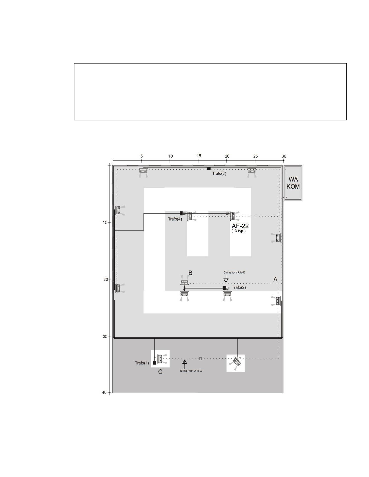
9.2.2.2 Determining the device requirements
AF-22 Capacity = 22 lbs/h (10 kg/h)
EXAMPLE 2 (continued)
For area 1:
11 units AF-22
For area 2:
2 units AF-22
4 units transformers (total)
The tube requirements for air and water supply depend on the tube run. It is determined on the basis of the ground
plan. For this example, the result is approx. 525 feet (160 m) of Nortec quick-assembly kit (SMB). The
SMB includes the necessary cables, low-pressure tubes and fittings. For further information on the tube
run, please see Chapter 4.3-4.5.
Figure 11: Example 2 schematic
The solid line stands for power supply, the dotted line for air and water supply. Dimension scale is shown in metres.
WA: Water treatment, if necessary
KOM: Compressor
Nortec AF-22 52002_A_EN_1611 25
Page 30
9.2.2.3 Determining the compressed air and water requirements
Compressed air requirements
The compressed air consumption of a system depends on the number of atomizers.
AF-22: 60 Nl/min
Related to the example and using the following values:
Area 1 = 660 l/h
Area 2 = 120 l/h
The result is an air volume of 780 l/h 1716 lbs/hr
NOTE:
In order to ensure a trouble-free operation, the compressed air system ought to deliver 1.2 times the air
volume that has been calculated.
Water requirements
The water consumption of a system depends on the number of atomizers.
AF-22 (22 lbs/h)
Related to the example and using the following values:
Area 1 = (243 lbs/h)
Area 2 = (44 lbs/r)
The result is an air volume of 287 lbs/h.
NOTE:
In order to ensure a trouble-free operation, the water system ought to deliver 1.2 times the maximum
water volume that has been calculated.
26 52002_A_EN_1611 Nortec AF-22
Page 31
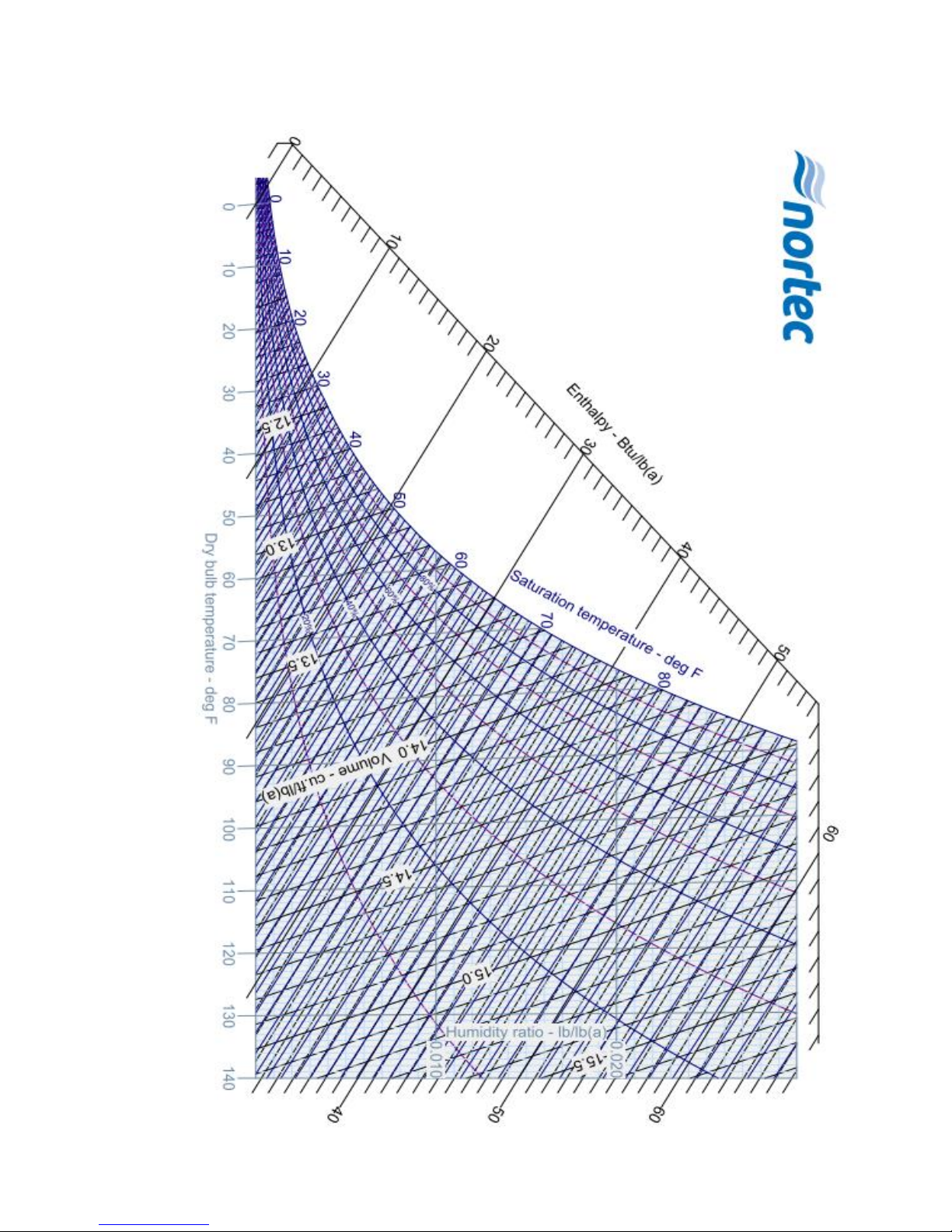
9.3 Psychometric Chart (Imperial)
Nortec AF-22 52002_A_EN_1611 27
Page 32
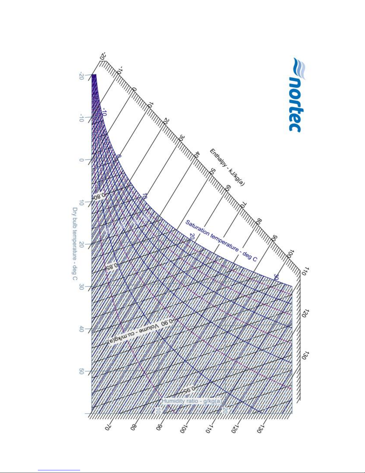
9.4 Psychometric Chart (Metric)
28 52002_A_EN_1611 Nortec AF-22
Page 33

Warranty
Nortec Humidity Inc. and/or Nortec Humidity Ltd. (hereinafter collectively referred to as THE COMPANY),
warrant for a period of two years after installation or 30 months from
manufacturer’s ship date, whichever date is earlier, that THE COMPANY’s manufactured and assembled
products, not otherwise expressly warranted (with the exception of steam cylinders), are free from defects
in material and workmanship. No warranty is made against corrosion, deterioration, or suitability of
substituted materials used as a result of compliance with government regulations.
THE COMPANY’s obligations and liabilities under this warranty are limited to furnishing
replacement parts to the customer, F.O.B. THE COMPANY’s factory, providing the defective part(s) is
returned freight prepaid by the customer. Parts used for repairs are warranted for the balance of the term
of the warranty on the original humidifier or 90 days, whichever is longer.
The warranties set forth herein are in lieu of all other warranties expressed or implied by law. No liability
whatsoever shall be attached to THE COMPANY until said products have been paid for in full and then
said liability shall be limited to the original purchase price for the product. Any further warranty must be in
writing, signed by an officer of THE COMPANY.
THE COMPANY’s limited warranty on accessories, not of the companies manufacture, such as controls,
humidistats, pumps, etc. is limited to the warranty of the original equipment manufacturer from date of
original shipment of humidifier.
THE COMPANY makes no warranty and assumes no liability unless the equipment is installed in strict
accordance with a copy of the catalog and installation manual in effect at the date of purchase and by a
contractor approved by THE COMPANY to install such equipment.
THE COMPANY makes no warranty and assumes no liability whatsoever for consequential damage or
damage resulting directly from misapplication, incorrect sizing or lack of proper maintenance of the
equipment.
THE COMPANY makes no warranty and assumes no liability whatsoever for damage resulting from
freezing of the humidifier, supply lines, drain lines, or steam distribution systems.
THE COMPANY retains the right to change the design, specification and performance criteria of its
products without notice or obligation
Nortec AF-22 52002_A_EN_1611 29
Page 34

Consulting, Sales and Service:
U.S.A.
835 Commerce Park Ave.
Ogdensburg, NY 1366-2209
CANADA
2740 Fenton Road
Ottawa, ON, K1T 3T7
Tel. 1.866.NORTEC1
Fax: 613.822.7964
Email: [email protected]
Website: www.humidity.com
30 52002_A_EN_1611 Nortec AF-22
 Loading...