

Page 1

NH Electrode
Steam Humidifiers
Installation,
Operation, and
Maintenance Guide
IMPORTANT: Read and save these instructions. This
guide to be left with equipment owner.
Form #03-172 1506262
Page 2

Table Of Contents
INSTALLATION 1
RECEIVING & UNPACKING EQUIPMENT ................................1
PRE-INSTALLATION CHECKPOINT ...................................1
BASIC HUMIDIFIER CONFIGURATION..................................1
LOCATION & MOUNTING .........................................2
HUMIDIFIERS ...............................................2
BLOWER PACKS .............................................2
STEAM DISTRIBUTORS..........................................3
PLUMBING .................................................3
WATER SUPPLY LINE...........................................3
DRAIN LINE ................................................3
STEAM LINE AND CONDENSATE RETURN LINE ............................4
ACCESSORIES - FILL CUP EXTENSION KIT(S) .............................4
ELECTRICAL................................................4
PRIMARY VOLTAGE SUPPLY WIRING TO HUMIDIFIER ........................4
LOW VOLTAGE CONTROL WIRING ...................................5
On-Off Controls.............................................5
CONTROL INSTALLATION ........................................5
OPTIONAL MODULATION (CONTINUOUS CONTROLS) ........................5
OPTIONAL MODULATION (CONTINUOUS CONTROL) PACKAGES BY NORTEC ...........7
OPERATION 7
INTRODUCTION ..............................................7
LAYOUT AND FUNCTION .........................................7
NHMC OPERATION ............................................8
START-UP SELF TEST ..........................................8
USER LEVEL................................................9
INFORMING THE USER ..........................................9
SELF-HELP ................................................9
SYSTEM MESSAGES ...........................................9
REMOTE INDICATION...........................................9
DOUBLE UNIT OPERATION .......................................9
NHB/NHP OPERATION ..........................................9
END OF CYLINDER LIFE .........................................9
MANUAL CAPACITY ADJUSTMENT...................................10
OTHER POTENTIOMETERS.......................................10
DETECTING WATER SUPPLY DEFICIENCY ..............................10
REMOTE INDICATION ..........................................10
DOUBLE UNIT OPERATION .......................................10
BLOWER PACK OPERATION ......................................10
Page 3

MAINTENANCE 10
WHEN TO REPLACE THE STEAM CYLINDER .............................10
HOW TO REMOVE THE STEAM CYLINDER ..............................13
MANDATORY CLEANING OF THE DRAIN VALVE ...........................13
HOW TO INSTALL THE REPLACEMENT CYLINDER ..........................14
BUILT ON AND REMOTE MOUNTED BLOWER PACKS (BOBP’S / RMBP’S) .............15
TROUBLESHOOTING 15
STARTING POINT ............................................15
USING THE WIRING DIAGRAM .....................................21
TERMS USED ..............................................22
WIRING DIAGRAM ..........................................23-25
PRE START-UP CHECKLIST ......................................26
START-UP CHECKLIST AND QUICK REFERENCE...........................27
MAINTENANCE CHECKLIST .....................................28-29
REPLACEMENT PARTS .......................................30-35
Page 4
INSTALLATION
pply
3. Report any discrepancy immediately.
RECEIVING & UNPACKING EQUIPMENT
1. Check packing slip to ensure ALL material has
been delivered.
2. All material shortages are to be reported to
NORTEC within 48 hours from receipt of goods.
NORTEC assumes no responsibility for any
material shortages beyond this period.
3. Inspect shipping boxes for damage and note on
shipping waybill accordingly.
4. After unpacking, inspect equipment for damage
and if damage is found, notify the shipper
promptly.
5. All NORTEC products are shipped on an F.O.B.
factory basis. Any and all damage, breakage or
loss claims are to be made directly to the shipping
company.
PRE-INSTALLATION CHECKPOINT
1. Ensure that available voltage and phase
corresponds with humidifier voltage and phase as
indicated on humidifier’s nameplate label (see
Figure #1).
2. Ensure that the dedicated external disconnect is of
sufficient size to handle the rated amps as
indicated on the nameplate label. Refer to local
codes.
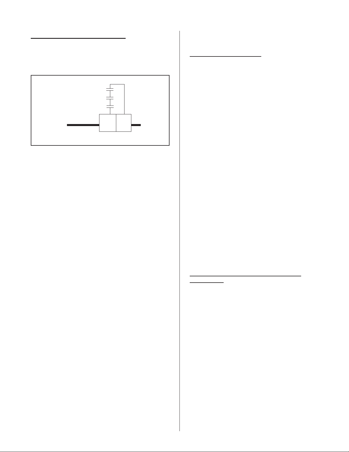
BASIC HUMIDIFIER CONFIGURATION
NORTEC humidifier models NHMC, NHP and
NHB share a modular sheet metal cabinet. Each unit
has a right side electrical compartment. Each
electrical compartment has a hinge-down front door
which is removable from any partially or fully opened
position. Each electrical compartment has a
screw-mounted right side cover which can also be
removed for ease of electrical connection. For safety,
the door when closed keeps the side cover from being
removed.
Single units have a plumbing compartment
attached to the left side of the electrical. Double units
have a second plumbing compartment. Each
plumbing compartment has a hinge-down front door
which is not intended to be removed. For safety, the
door must be closed in order to engage the shared
lock. To avoid any danger, never operate the
humidifier with a door off. For safety, each door when
closed engages its own safety interlock switch. All
switches must be engaged before the unit will operate.
To open the doors, unlock key, lift door up slightly
and pull top of door forward. Door will hinge 180
degrees and hang straight down. To remove door,
swing door parallel to floor. Then lift up slightly and
out. To reinstall door, hold parallel to floor and insert
hinge pins at bottom.
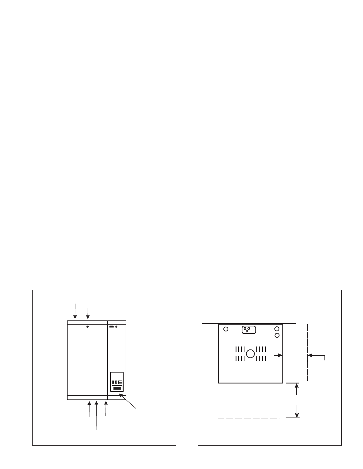
Condensate
Return
Figure #1
NH Series Humidifier
Steam
Outlet
Drain
Nameplate
Label
Water
Su
Power And
Control
Wiring
Clearance Requirements
WALL
WITHOUT BLOWER PACK
TOP VIEW
NOTE: LOCAL AND NATIONAL
CODES MAY DEVIATE. PLEASE
CONSULT APPLICABLE CODES
FOR CLEARANCE REQUIREMENTS
IN ALL CASES.
Figure #2
MIN. 36"
FRONTAL
CLEARANCE.
MIN. 36"SIDE
CLEARANCE
RECOMMENDED.
SEE NOTE.
-1-
Page 5
LOCATION & MOUNTING
g
HUMIDIFIERS
NH Series humidifiers are designed to mount on a
suitable wall or vertical surface. Do not sit on floor due
to clearances required for plumbing, electrical, and
control entrances. The clearance dimensions shown
in this manual are for reference only and are the
minimum required for maintenance of the humidifier.
Local and National Codes should be consulted prior to
final location and installation of the humidifier.
NORTEC can not accept responsibility for installation
code violations.
1. Location of the humidifier should be below and as
close as possible to the steam distributor location
as possible.
2. For front and side clearance requirements (for
access during installation, maintenance and
troubleshooting), see Figure #2.
3. If possible, DO NOT locate humidifier any further
than absolutely necessary from steam distributor
location, as net output will be reduced as a result
of heat loss through steam hose (see Engineering
Manual, Form -163D). Also, increased static
pressure may necessitate using an accessory fill
cup extension kit.
4. Where possible, mount humidifier at a height
convenient for servicing.
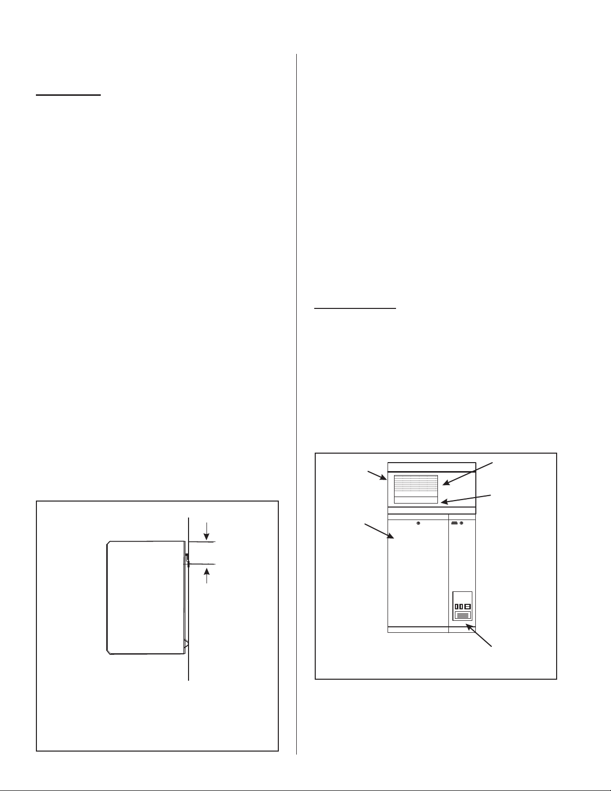
5. Wall mounting bracket provided should be
securely attached horizontally and open edge
upwards, using field-supplied fasteners. Use a
minimum of 3 - #12 x 3" long wood screws, or
Figure #3
Wall Bracket Mounting Detail
WALL
Wall
better, into a vertical structural surface. If any
spacer material is used between the bracket and
the structural material such as drywall, increase
fastener length accordingly. In addition, install a
minimum of 2 field supplied fasteners in the holes
provided in the back of the unit to prevent the unit
from being bumped off the wall bracket. See
Figure #3.
6. Make sure humidifier is level.
7. DO NOT mount humidifier on hot surfaces.
8. If humidifiers are mounted on roof, a
thermostatically ventilated weatherproof cabinet by
others should be used. Consult factory.
9. DO NOT mount humidifiers in an area where
freezing may occur. Use an accessory Low
Temperature Protection Kit, if necessary.
10. DO NOT mount humidifiers on vibrating surface.
Consult factory.
BLOWER PACKS
1. Blower packs are an optional accessory used to
directly distribute steam to localized areas (such
as computer rooms) or in structures that do not
have a built-in air distribution system.
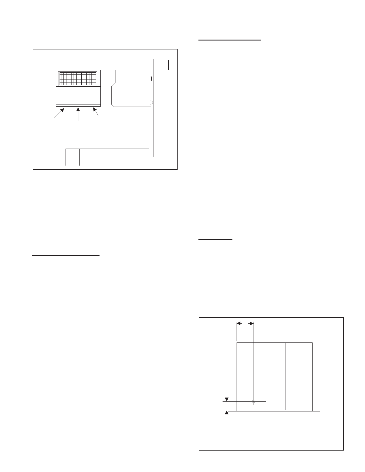
2. Blower packs are available integrally-mounted on
humidifier (built-on blower pack, BOBP, see Figure
#4) or detached and field-piped and wired to
humidifier (remote mounted blower pack RMBP,
see Figure #5).
Figure #4
Built On Blower Pack (BOBP)
Optional
Built-On
Blower Pack
Single
Circuit
Humidifier
Built-In
Supply Air
Grille
Built-In Steam
Distributor
Fasten wall bracket
FASTEN WALL BRACKET
(FACTORY SUPPLIED) TO
(Factory supplied) to
WALL USING ANCHOR BOLTS
wall using field supplied
(3) SUPPLIED BY OTHERS
fasteners.
005-030
7.7 (19.6cm)
050-200
7.7 (19.6cm)A
7.7”
A
(19.6 cm)
3. All NH Series blower packs consist of a steel
cabinet containing: blower/motor powered by
voltage directly from the humidifier, fuse, relay,
speed select switch (in NH-050 and larger),
stainless steel steam distributor, supply air grille
with adjustable louvers, and built-in manual reset
-2-
Power And
Control
Wirin
Page 6
Wall
Figure #5
)
Remote Mounted Blower Packs (RMBP)
Side
050-100
3.2" (8.0cm)
Condensate
Front
Steam
A
Power and control
wiring from humidifier
005-030
3.2" (8.0cm)
safety thermostat to turn off the humidifier if the
blower pack gets overheated. Control thermostat,
mounted on the steam distributor, starts the fan
when steam is generated. When supply voltage
differs from voltage required to run blower motor,
blower pack will contain a proper transformer. All
blower packs provide intake air filters.
For installation details about the blower pack,
please refer to the blower pack installation manual
located in the blower pack box (Form #XX-239).
WATER SUPPLY LINE
1. Humidifier is intended to operate on potable (cold)
tap water.
2. If the raw water is very hard, NORTEC can
A
provide longer cylinder life on softened water.
However, softened water is more conductive and
more corrosive. Some hardware and/or software
changes may be required, at time of order or in the
field. Consult factory.
3. If RO or DI is available, blending may increase
cylinder life. Consult factory.
4. DO NOT use a hot water supply to humidifier.
Minerals will adhere more easily to surfaces and
the fill valve’s small flow regulating orifice and
could become plugged.
5. Standard fill valves are sized for water pressure
ranging from 30 to 80 psig (ideally 55 to 60 psig).
For other pressures, consult factory. This
pressure should be measured at the humidifier if
the water pressure is suspect.
6. ALWAYS supply and install a shut off valve in the
water supply line dedicated to the humidifier to
facilitate servicing. Use ½" OD copper to within 4
feet of the humidifier. Reduce copper to 3/8" OD
and connect to the factory-supplied 3/8" olive
compression fitting under the humidifier.
DRAIN LINE
STEAM DISTRIBUTORS
1. Steam distributors are used in ducts or air
handling units, and are made of stainless steel.
2. Steam distributors can be in vertical or downflow
applications.
3. Proper location should consider: air temperature,
relative humidity before the distributor, air velocity,
dimensions of the location, amount of steam
introduced into the duct, downstream obstructions,
and surfaces vulnerable.
4. For installation details, please refer to steam
distributor installation manual located in the
distributor box (Form #XX-231).
5. For calculating absorption distances, refer to
H.E.L.P. Software or steam distribution and
absorption distances engineering manul (Form
#XX-232).
PLUMBING
All water supply and drain line connections
should be installed in accordance with local
plumbing codes.
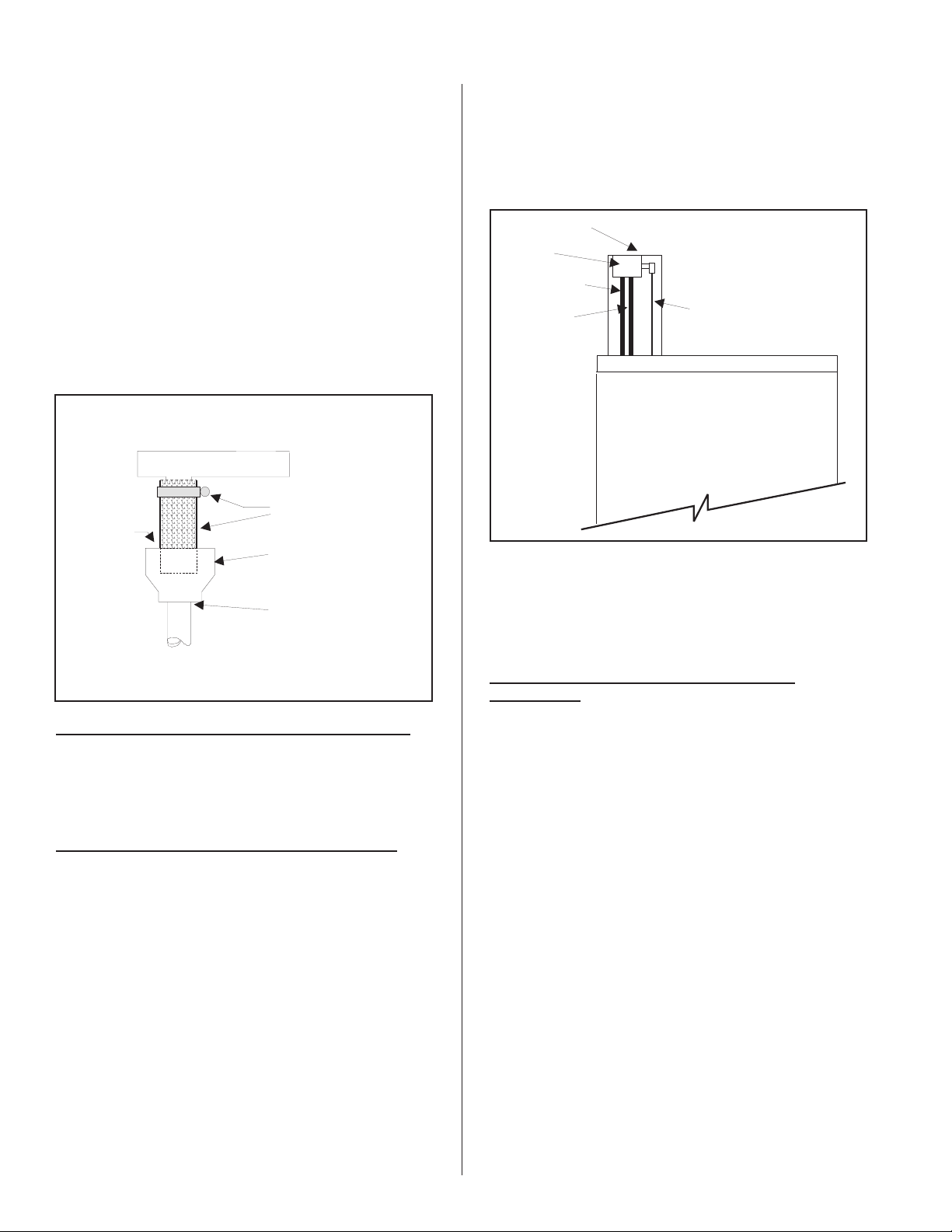
1. Humidifier is equipped with a 7/8" O.D. unthreaded
drain outlet on underside of drain canal on bottom
of the humidifier (see Figure #6). A field-supplied
funnel (see Figure #7) is recommended. It will
prevent backup in the drain pan and in the cylinder
due to partially blocked or badly installed drain
lines. This prevents rusting of the drain pan and
arcing due to over-concentration. The drain canal
Figure #6
Drain Line Connection
A
B
Model
005 -030
050 -100
150 -200 Left
150 -200 Right
Bottom View
Ain.(mm)
1.0 (25)
2.2 (55)
2.2 (55)
2.2 (55)
B in.(mm)
5.0 (127)
6.2 (158)
6.2 (158)
19.6(498
Wall
-3-
Page 7
has been improved to prevent backup despite long
e
A
or gently sloped drain lines but it can not
compensate for flat or uphill runs.
2. The drain line should not end in a sink used
frequently by personnel, or where plumbing codes
prohibit it. Route to a floor drain or equivalent for
safety reasons, since drain water from humidifier
can be very hot.
3. Keep drain lines as short as possible. Keep drain
lines sloped down, not level and not up since
low spots in drain lines will accumulate
sediment and cause backup. The drain line
should be 7/8" O.D. copper pipe or larger. Do not
use plastic pipe for drain lines. Consult factory.
Figure #7
Drain Connection
ClampAnd
1.5” I.D.Hose
ir Gap
NOTE: Steam hose should not reach bottom of the funnel.
Factory Supplied
Stainlesssteel Reducer To
ServeAs Funnel
Drain (ByOthers)
2" O.D. StainlessSteel Pipe
Or 2" I.D.DI Compatible Hos
(Not Supplied)
4. To increase allowable water column (allowable
positive static pressure) an accessory Fill Cup
Extension Kit is available from NORTEC. See
Figure #8.
Figure #8
Fill Cup Extension Kit to Overcome Static Pressure
Fill Cup Bracket
Fill Cup
Overflow Hose
Fill Hose To
Cylinder
Hose From FillValve
5. Water column requirements are even higher duct
static pressure when distributor’s steam outlets
are faced with downflow duct applications.
ELECTRICAL
PRIMARY VOLTAGE SUPPLY WIRING TO
HUMIDIFIER
STEAM LINE AND CONDENSATE RETURN LINE
1. Check and ensure that available voltage and
phase corresponds with operating voltage and
1. Refer to the installation manual of the steam
distribution system used in your application.
phase of humidifier as indicated on the humidifier
nameplate label (see Figure #1).
Steam Distribution - Form #XX-231, SAM-e - Form
#XX-249, Blower Pack - Form #XX-239.
2. Ensure that an adequate power supply is available
to carry full humidifier amperage drawn as
ACCESSORIES - FILL CUP EXTENSION KIT(S)
1. The NH Series humidifier is an electrode
humidifier. It produces steam at atmospheric
pressure. Pressure head must develop to push
steam through supply line and into air duct.
2. Combined resistance of duct positive static
pressure and steam line resistance creates a
small pressure head in steam cylinder. Total
amount of positive static pressure head is
reflected directly by water column differential that
develops between water in the fill cup hose
feeding cylinder and water level in cylinder.
3. Standard dimensions of humidifier limit static that
can be tolerated before water will be pushed high
enough to spill over into overflow tube in fill cup
assembly.
specified by rated amps on the humidifier
nameplate label refer to local codes.
3. A dedicated external disconnect must be installed.
Do not exceed the maximum circuit protection
amps as indicated on the nameplate label.
4. Optional internal primary fuses are not intended to
substitute for external fuses. Internal primary
fuses are a factory added option (when specified)
to protect internal primary wires individually.
5. Connect ground wire to cabinet ground clamp. Do
not use neutral wire of four wire supply as ground.
6. Single phase humidifiers may be run on three
phase power, but load may unbalance power grid.
7. External wiring sizes must be in accordance with
NEC and/or CEC and existing local electrical
codes and by-laws.
-4-
Page 8
LOW VOLTAGE CONTROL WIRING
On-Off Controls
Figure #9
External Wiring of On/Off Controls
A
B
C
4. Each humidifier is supplied with a wiring diagram
inside.
CONTROL INSTALLATION
1. Mount any wall humidistat (control or high limit)
over standard electrical box at height similar to
typical thermostat. Any wall humidistat should
be in location representative of overall space
being humidified and not in path of blower pack or
air supply grille. Do not mount on a outside wall
where temperature fluctuation can affect control
response.
EXTERNAL
810
INTERNAL
Controls are available from NORTEC as
accessories. If controls were not ordered with
humidifier, they must be purchased supplied by others.
The following information is relevant to all controls,
factory supplied or otherwise.
A, B and C (described below) are to be wired in
series (only one path for current) across terminals 8
and 10 on the low voltage control terminal strip, or
replaced with a jumper wire for constant operation.
Caution: this is the “hot” wire from the 24V control
transformer; it will blow the 3A fuse if any control field
wiring touches ground metal.
A - Wall or Duct Mounted Control On/Off
Humidistat: Wired to make on drop in humidity, break
on rise to setpoint. Set to desired % RH. Can be a
make/break set of contacts from a Building Automation
System.
B - Duct Mounted Safety High Limit On/Off
Humidistat (if used): Wired to make on drop in
humidity, break on rise to safety setpoint. Set to
approximately 85% RH as a safety to help prevent
saturation and wetting in the duct.
C - Duct Mounted Safety Air-Proving On/Off
Switch (if used): Wired to make when sensing air
flow, break when no air flow. Used as a safety to
prevent saturation when no air flow.
1. NORTEC offers various versions of A, B and C to
suit each application. In general, A is essential,
whereas B and C are highly recommended in
ducted applications.
2. Field wiring from humidistat to humidifier and
between devices should be 18 AWG or heavier
and kept as short as possible.
3. Low voltage control terminal strips are provided in
the electrical compartment. Internal sides are
factory wired. External sides are to be field wired.
2. Mount duct humidistat in location representative
of overall air humidity, usually return duct. Do not
mount it directly in front of steam distributor or in
turbulent or mixing zone. Mount it where air’s
humidity and temperature are uniform and
representative of spaces being humidified.
3. Mount duct high limit humidistat downstream of
steam distributors far enough that, under normal
humidity and air flow conditions, steam will have
been fully absorbed (typically at least 10 feet). It
must be located to sense high humidity only when
uniform and representative air is over-humidified
or approaching saturation.
4. Mount duct air-proving switch so that it is able to
sense air flow or lack of it. Wire it to make when
air flow is sensed and break when air flow fails.
5. Check operation of all on/off controls before
starting humidifier.
6. Calibration of controls (on/off or modulation) in the
field may be necessary due to shipping and
handling. Verify humidistat accuracy before
commissioning system.
OPTIONAL MODULATION (CONTINUOUS
CONTROLS)
1. Read on/off controls section first since it is
necessary to all control systems.
2. Virtually any modulation (continuous control)
external hardware by others (as long as it has
%RH setpoint circuitry) may be interfaced with
pre-specified factory-configured NHMC/NHP
Series pc board via the control terminal strip. The
NHB can be used with on-off control only. Use
shielded cables for modulation circuits.
3. Modulation (continuous control) by others for use
with NHMC/NHP Series humidifiers involves one
of several control wiring diagrams. In all cases,
modulating signal interfaces through control
terminal strip to main pc board inside humidifier.
4. The modulation signal must increase from
minimum toward maximum as sensed RH (actual
RH) drops below desired RH (%RH setpoint). In
response, humidifier’s steam output will increase
from minimum toward maximum. When
humidifier’s steam output (lbs/hr) matches
humidification load (lbs/hr), modulation signal will
stabilize.
-5-
Page 9
l
l
l
(ACTUAL)
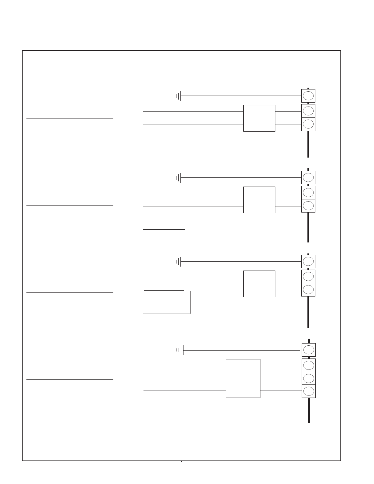
Figure #10
Primary Voltage Supply Wiring
PRIMARY (LINE) VOLTAGE WIRING TO UNITVOLTAGE
(BY OTHERS)
L1
L2
- Single Phase Unit.
- Single Phase Supply.
- Required Voltage Between L1 And L2.
- Load Balanced.
L1
L2
L3
Neutral
L1
L2
L3
Neutral
Ground
Ground
- Single Phase Unit.
- 3 Phase Supply.
- Required Voltage Between L1 And L2.
- Load Will Be Unbalanced.
Ground
- Single Phase Unit.
- 3 Phase Supply.
- Required Voltage Between L1 And Neutral.
- Load Will Be Unbalanced.
Ground Wire
Dedicated
Disconnect
Ground Wire
Dedicated
Disconnect
Ground Wire
Dedicated
Disconnect
Circuit
Breaker
Or
Circuit
Breaker
Or
Circuit
Breaker
Or
Ground
Leg
2 Pole
Termina
Block
E
I
X
N
T
T
Ground
Leg
2 Pole
Termina
Block
E
I
X
N
T
T
Ground
Leg
2 Pole
Termina
Block
E
I
X
N
T
T
Ground Wire
L1
L2
L3
Neutral
Ground
Dedicated
Circuit
Breaker
Or
Disconnect
- 3 Phase Unit.
- 3 Phase Supply.
- Required Voltage Between Any Two Legs.
- Load Will Be Balanced.
NOTE: VoltageAt TerminalBlockMust Be InAccordance WithSpec.Label.
All Wiring ToBeInAccordance With Existing NationalAnd LocalElectrical Codes.
-6-
Ground
Leg
3 Pole
Terminal
Block
E
I
X
N
T
T
Page 10
5. Field-wiring connections for modulation control are
to be made to external side of terminals 26, 28, 30
and 32 on humidifier’s control terminal strip.
Always refer to the external control’s wiring
diagram factory supplied with each NORTEC
modulation control option.
6. Varying dc Voltage Modulation Signal Powered
by Others: NHMC/NHP Series humidifier can be
factory configured to accept the following vdc
signals: 0-3 vdc, 0-10 vdc, 0-16 vdc, 0-20 vdc, 1-5
vdc or 2-10 vdc. Wire according to NORTEC
supplied external wiring diagram that comes with
each modulation option. To share the signal with
more than one humidifier, wire in parallel to each
humidifier. If a different signal is desired consult
factory.
7. Varying dc milliAmp (mA) Modulation Signal
Powered by Others: NHMC/NHP Series
humidifier can be factory-configured to accept a
standard dc mA signal, if pre-specified. Wire
according to NORTEC supplied external wiring
diagram that comes with each modulation option.
Choose from 0-20 dc mA or 4-20 dc mA. To share
the signal with more than one humidifier consult
factory.
8.
Varying Resistance (W) Modulation by Others:
NHMC/NHP Series humidifiers can be factory
configured to power a 3-wire varying resistance
modulation humidistat by others, if pre-specified.
Wire according to NORTEC supplied external
wiring diagram that comes with each modulation
option. Choose from 0-135W, 0-500W or up to
0-1000W. To share the signal with more than one
humidifier consult factory.
pre-selected when ordering the option. NORTEC
offers several packages for NHMC/NHP Series
humidifiers. Wire according to NORTEC supplied
external wiring that comes with each optional
modulation package.
3. Optional modulation packages without modulating
safety high limit can use on-off safety high limit.
Refer to on-off controls section.
4. All versions can use on-off safety air proving
switch. Refer to on-off controls section.
OPERATION
INTRODUCTION
The NORTEC NH Series humidifier is a
completely new design based on up-to-date
technology. The NHB is designed to provide clean
steam humidification at an economical price. It utilizes
NORTEC’s patented electronic Auto-Adaptive internal
control system for high efficiency, low waste of water
and electricity.
The NHP and NHMC utilize NORTEC’s patented
P+I Auto-Adaptive control for greater control of the
space humidity. Both the NHP and NHMC use a
micro-computer control system for greater flexibility.
The NHMC has a liquid crystal display (LCD) to
indicate system messages, display RH and
temperature. The NHMC can accept dual modulation
signals and is NORTEC’s most advanced model.
OPTIONAL MODULATION (CONTINUOUS
CONTROL) PACKAGES BY NORTEC
1. Modulation (continuous control) “packages” are
offered as accessories by NORTEC. Power
supply comes from inside NHMC/NHP Series
humidifiers.
Figure #11
Generalized Modulation Wiring
VariesWith Each
Modulation Option
See NORTECSupplied
External Wiring Diagram
_
y
z
+
NHMC/NHP
External
Internal
A
B
C
810 32 30 28 26
2. NORTEC provides the humidity set point circuitry
and sensor(s) for wall or duct mounting or both
(only applies to NHMC. NHP is only capable of
single channel continuous control modulating) as
LAYOUT AND FUNCTION
The NH Series humidifiers consist of a plumbing
and an electric compartment. In every case there is at
least one steam distributor (SD) for installation in air
ducts or blower packs (built on: BOBP, remote
mounted: RMBP) for direct space humidification.
Water enters the steam cylinder through the
bottom via the drain valve from the fill cup assembly
when the 24 volt fill valve solenoid is energized. When
water submerges the electrodes, the minerals in the
water conduct current that heats the water and
produces sterile steam for distribution into the air. The
minerals in the water remain in the cylinder which is
periodically drained to maintain optimum performance
and cylinder life.
Primary electric power is applied to the electrodes
in the steam cylinder when the on/off switch is pushed
on and all controls options are calling. A primary to 24
volt stepdown transformer provides power to the
contactor holding coil(s) via the main control board.
The humidifier’s operating status is reported to the
user by the green and yellow indicator lights on the
front of the unit as shown in following table.
-7-
Page 11
SIGNAL LIGHT STATUS
NHMC OPERATION
YELLOW GREEN
OFF OFF Off
OFF ON Normal operation
ON ON Replace cylinder or normal
startup operation
ON OFF Operation fault
The prerequisites for getting power and water into
the steam cylinder are as follows:
on/off/drain switch must be switched on
-
control circuit 8-10 must be made
-
modulation humidistat, if present, must be calling
-
control circuit 82-83 must be made
-
control circuit 84-85 must be made
-
cabinet mounted humidistat, if present, must be
calling
- door interlock switch must be made (interlock switch
can be pulled out to operate unit)
START-UP SELF TEST
Observe the LCD display when the on/off/drain
switch is first pushed on. The microcomputer pc board
will check the system components, display in words
what it is doing and provide a message if any faults
are found. The start-up self-test sequence will be
displayed as follows:
LCD EXPLANATION/COMMENTS
(WHAT YOU READ)
CONDAIRMATIC MC Note the V number. It tells you
the EPROM version.
NORTEC V2...
CONDAIRMATIC MC Note the model type. Ensure
NHMC (model type) compatibility
with spec label (name plate).
Can be reconfigured if
necessary.
SYSTEM TEST Test begins.
LAMP GREEN Observe green signal light on
LAMP YELLOW Observe yellow signal light on
Most water does not contain enough conductivity
for full boil on initial start-up. Units will need to
concentrate the water over a time period (hours to
days). During this process both lights are on.
CONTACT RELAY 1 Provides 24 VAC to 61-20 and
DRAIN VALVE Observe 24 volt solenoid
INLET VALVE Observe 24 volt solenoid
CONTACTOR Observe 24 volt coil activated
CONTACT RELAY 2 Provides 24 VAC to 63-36 and
CONTACT RELAY 3 Provides 24 VAC to 62-40 and
INTERNAL TEST Completion of self test.
LAMP
GREEN-YELLOW
INTERNAL TEST
external optional yellow lamp at
control strip to simulate a fault.
activated on drain valve.
activated on fill valve.
on contactor OR fan activated on
blower pack if present.
external optional red lamp at
control strip to simulate cylinder
spent.
external optional green lamp at
control strip.
Observe green and yellow
lamps pulse on together as sign
that all passed.
-8-
STEAM OUTPUT
INTERNAL TEST
sensor, the LCD will read “MAXIMAL LEVEL”.
NOTE: If cylinder water reaches the full cylinder
Begins normal operation and
displays lbs/hr.
Page 12

USER LEVEL
REMOTE INDICATION
The keypad has four keys: MENU, é , ê,
ENTER.
Each time the user presses the menu key, the
microcomputer will display on the LCD the next
operating parameter on the menu. The basic display
will read:
Steam output (lbs/hr)
-
Capacity demand
-
Limited capacity
-
Control signal y
-
The display loops back to the top of the menu the
next time the user presses the menu key. As
NORTEC software updates are incorporated, new
parameters will automatically be added to the menu.
INFORMING THE USER
The microcomputer continually monitors the
operating status and informs the user in four ways.
The first (signal light status), second (optional external
lamps tied to the control strip) and third (operating
parameters displayed on the alphanumeric LCD
display) have been discussed. The fourth way is to
interrupt the LCD and display a system message. It
only does this as a last resort.
SELF-HELP
The microcomputer applies corrective actions
whenever its self-diagnostics identifies a problem that
it is able to correct by itself. If the corrective action is
not successful then it displays a system message. If
the corrective action requires a service person, then
the microcomputer’s only resort is to stop the unit and
display a system message. The unit never stops
unless it has to.
After three days of no call from either the on/off
controls or the modulating controls, the drain valve is
automatically activated long enough to drain all water
from the steam cylinder. This NORTEC exclusive
feature will prolong the life of the cylinder.
SYSTEM MESSAGES
Alphanumeric system messages will appear on
the LCD display any time the microcomputer decides
the user must be informed. The microcomputer does
not stop the unit for all system messages. (See the
Troubleshooting Section in this manual)
The NHMC is always internally wired to provide 24
VAC to the terminal strip for optional external remote
indication. Up to 100 milliamps is available at each of
three terminal pairs (61-20, 62-40, 63-36) for activating
yellow, green and red lamps ordered as options from
NORTEC or for powering field-supplied resistive loads
such as lamps.
DOUBLE UNIT OPERATION
Turn both switches on. During start-up self test
both sides respond to the self test together. Watch for
the lamps to light and the drain, fill and contactor to
energize as described on page 15. The LCD,
however, only indicates the left circuit [1].
After the self test, the LCD will display the steam
output for the left side [1] and both sides will operate
normally.
To alternate between parameters for the left side
[1] and parameters for the right side [2], press the
Enter key.
Use the MENU key to see other parameters
besides steam output. To display steam total output
for both sides press the enter key until [S] is displayed.
When a fault occurs on the right side of the double
unit, both sets of lamps (and remote relays) will come
on indicating that a fault has occurred. The left
[master] will display its own faults.
The LCD will indicate which fault has occurred and
on which side of the unit, [1] or [2]. The side not
faulted will continue to operate as usual.
Display is not available for the right side [2] if the
left side is switched off.
NHB/NHP OPERATION
END OF CYLINDER LIFE
When the cylinder is used up and water level can
no longer stabilize below full cylinder (due to fully
coated electrodes), the yellow light will come back on,
in addition to the green light. The disposable cylinder
must be replaced.
Although “both lights on” is the same signal at
start-up as it is at end of cylinder life, the age of the
cylinder enables the user to know when “both lights
on” is indicating end of cylinder life. It is wise to keep
a new replacement cylinder on hand to avoid
downtime when it becomes time to change the
disposable cylinder. (See Troubleshooting section.)
-9-
Page 13

MANUAL CAPACITY ADJUSTMENT
The NHB humidifier is rated in lbs/hr of steam
output capacity. Set to 100%, it will operate at full
output until the humidistat has sensed that the
humidity has reached setpoint. Then it will stop the
humidifier by breaking control circuit 8-10.
If the humidifier is oversized, the humidistat will be
quickly satisfied and stop the humidifier. As humidity
level drops the humidistat calls again. It is quickly
satisfied and stops again. The resultant short-cycling
is easily overcome.
A manual capacity adjustment potentiometer
(“pot”) is provided on the NHB main pc board for that
purpose. It is marked “Sx%” and is adjustable from 20
to 100% of rating.
The NHP humidifier, utilizing modulation control,
does not have the same problems of oversizing. It
reacts to the modulation signal and varies its capacity
automatically. However, if you wish to turn down the
capacity, the NHP has the same manual capacity
adjustment potentiometer (“pot”) that the NHB has.
OTHER POTENTIOMETERS
On the NHP, the optional output indication meter
will steadily increase until the meter reads maximum
output. Maximum output depends on the manual
capacity setting of the unit and/or the continuous
control demand.
The NHB/NHP has built in diagnostic capabilities
and will shutdown for the following reasons:
No current (similar to NHMC Error Message 5).
-
Excess current (similar to NHMC Error Message 1).
-
Change cylinder/end of life (similar to NHMC Error
-
Message). NHB will shutdown on this fault.
In all cases, when an error is detected, there will
be 24 VAC potential (100 mA max.) available at
terminals 20 and 61 of the internal external white
terminal strip.
BLOWER PACK OPERATION
Blower packs are equipped with a control
thermostat mounted on the steam distributor. As soon
as humidifier generates steam, the contact is closed
and the fan is started. When steam is no longer being
generated, the fan cuts out with a delay.
Do not adjust any other potentiometers (“pots”) on
the pc board(s). They are factory-set and not meant to
be user-set.
DETECTING WATER SUPPLY DEFICIENCY
Knowing how long it normally takes to fill each size
steam cylinder, each humidifier’s pc board is factory
configured to an acceptable maximum filling time
(using jumpers). If it is filling too slowly, when the time
expires the electronics stops the humidifier. To
indicate this, the green light goes out and the yellow
light goes on.
REMOTE INDICATION
Every NHB/NHP comes factory wired to provide
24 VAC (100 mA max.) at 61-20 on the control
terminal strip. The user can connect an indicator
externally to 61-20. It will automatically be activated
any time the yellow light is on. It will therefore be
activated whenever the humidifier shuts off due to
excess current or water deficiency. It is also normal
for it to be activated on start-up.
DOUBLE UNIT OPERATION
Turn both switches on. If there is a demand for
humidity, the green status lamp will indicate that the
circuit is operating.
If blower packs get overheated (malfunction of the
air circulation), the manual reset safety thermostat
interrupts the steam generation. To reset, switch off
the humidifier and wait until the steam distributor cools
down. Then remove left-hand side intake air filter and,
using a screwdriver, press the reset button (marked
with a red dot) inside the blower packs.
Units are equipped with speed select switch. The
switch is located on the right-hand side of the blower,
inside the blower pack. To access the switch, remove
right-hand side intake air filter.
To avoid condensation on the cabinet parts, run
blower pack on high speed when humidifier delivers 75
lbs/hr or 100 lbs/hr of steam.
MAINTENANCE
WARNING! The plumbing and electrical
compartments contain high voltage components and
wiring. The access door(s) is equipped with a lock.
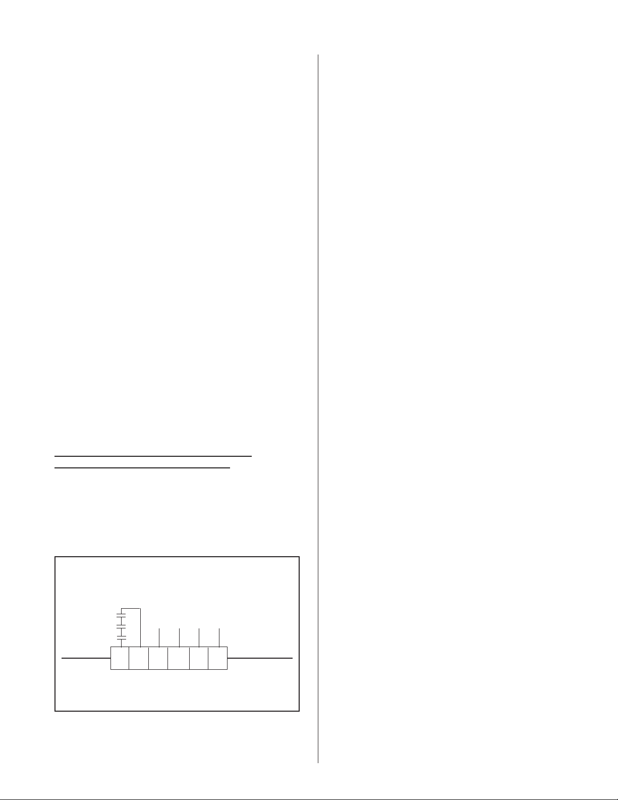
Access should be limited to authorized personnel only.
WHEN TO REPLACE THE STEAM
CYLINDER
The steam cylinder is disposable and must be
replaced at end of cylinder life. Cylinder life is
-10-
Page 14

dependent on water supply conditions and humidifier
(
)
usage. Failure to replace the cylinder at the end of
cylinder life may result in unit damage. NORTEC is
not responsible for any damages resulting from, or
attributable to, the failure to replace a used cylinder
(see Manufacturer’s Warranty). There are many
indications, each of which signifies the end of cylinder
life.
NHMC
1. After a period of operation (not on initial start-up),
the water level will approach the top of the
cylinder. (Life varies from 500 to 2000 operating
hours, as illustrated in Figure #12.)
Figure #12
Water Conditions vs. Cylinder Life
Capacity Adjustment Setting
100% 50% 25%
30
20
10
Grains of Hardness
500
400
200
3
CaCO mg/L (ppm)
6. The three (3) messages that will appear in
sequence are “MAXIMAL LEVEL”, then
“CYLINDER SPENT”, and finally “CYL. LIFESPAN
END”. The yellow unit status lamp will be on
during all three.
7. The green unit status lamp, primary contactor and
steam output will stop at “CYL. LIFESPAN END”.
This distinguishes it from “MAXIMAL LEVEL” and
“CYLINDER SPENT”.
8. Each of these three (3) messages has a unique
combination of responses at the terminal strip for
remote indication. These unique combinations
distinguish them from each other and from any
other system message.
9. At “MAXIMAL LEVEL” remote yellow-green-red
are OFF-ON-OFF. (Note that “MAXIMAL LEVEL”
will also appear at unit start-up.)
10. At “CYLINDER SPENT” remote yellow-green-red
are OFF-ON-ON. In other words, the red comes
on as the cylinder ages from “MAXIMAL LEVEL”
to “CYLINDER SPENT”. This gives the user
ample warning (remote red on) to replace the
cylinder before the NHMC shuts itself down.
11. At “CYL. LIFESPAN END” remote
yellow-green-red are ON-OFF-ON. In other
words, the remote green goes off and the remote
yellow comes on in addition to the red if
“CYLINDER SPENT” remains unchanged for
approximately three (3) days.
5
500 1000 2000 4000 8000
Cylinder Life Expectancy
average operatinghours
100
2. There will be reduced output in spite of a 100%
capacity setting and/or an unsatisfied demand
from the humidistat for more humidity. This is
evident by monitoring the unit’s output on the LCD
(liquid crystal display) with up to two lines of
continually updated alphanumeric information for
the user.
3. Each NHMC humidifier has an internal
micro-computer that can detect end of cylinder life.
If the cylinder is not changed, the humidifier will
automatically shut down.
4. The unit’s yellow status lamp is activated anytime
there is a system message sent to the LCD where
two lines of alphanumeric information await the
user. System messages are explained in greater
detail later in this manual. Three (3) different
messages will appear, in sequence, as the
cylinder goes from new to spent to needing
replacement.
5. The NHMC is pre-programmed to inform the user
of the cylinder’s status. It is important to
understand the significance of the unit’s system
messages, status lamps and 24VAC circuits for
remote indication. Figure #2 summarizes these
messages and responses.
12. The NHMC is always internally wired to provide
24VAC to the terminal strip for optional external
remote indication. Up to 100 mA is available at
each of three terminal pairs (61-20, 62-40 and
63-36) for activating yellow, green and red optional
external remote indicators, respectively. Any or all
of these remote indicators can be utilized. They
can be field-supplied resistive 24 VAC loads such
as lamps or ordered as options from NORTEC.
NHB/NHP
1. There will be reduced output in spite of a 100%
capacity setting and/or an unsatisfied call from the
on/off humidistat for more humidity. The NHP has
an output display where you will observe that the
capacity of the unit is decreasing.
2. Each NHB/NHP humidifier has a yellow status
lamp, a green status lamp, and a relay for remote
indication. Double units (models NH 150-200)
have two of each.
3. The yellow and green status lamps are long-life
LED’s (light emitting diodes) not incandescent
lamps.
4. The yellow and green status lamps are to be
viewed as a pair. This way, they convey four
-11-
Page 15

SYSTEM MESSAGE
DISPLAYED ON LCD
Figure #13
System Messages and Responses (EPROM : 2.XXN)
NHMC
UNIT STATUS LAMPS REMOTE INDICATION (24 VAC TO:)
UNIT
CONTACTOR YELLOW GREEN
61-20
“YELLOW”
62-40
“GREEN”
63-36
“RED”
Maximal Level
Excess Current / Error 1
No Current / Error 2*
Max. Filling Time / Error 3
Cylinder Spent / Error 4
No Current / Error 5
Output Too Low / Error 6
Electronic / Error 7
Phase Interrupt / Error 8
Cyl. Lifespan End / Error 9
* When No Current/Error 2 is displayed, display will change to show Maximal Level and will alternate back and forth.
SYSTEM FAULTS* UNIT CONTACTOR YELLOW GREEN “YELLOW” 61-20
ON ON ON OFF ON OFF
OFF ON OFF ON OFF OFF
OFF ON OFF ON OFF OFF
OFF ON OFF ON OFF OFF
ON ON ON OFF ON ON
OFF ON OFF ON OFF OFF
OFF ON OFF ON OFF OFF
OFF ON OFF ON OFF OFF
ON ON OFF OFF OFF OFF
OFF ON OFF ON OFF ON
NHP
UNIT STATUS LAMPS REMOTE INDICATION
(24 VAC TO:)
Maximal Level
Excess Current
No Current
Max. Filling Time
Cylinder Spent
No Current
Output Too Low
Electronic
Phase Interrupt
Cyl. Lifespan End
-
Remote indication 61-20 “yellow” means humidifier has shutdown and one of several system messages is showing.
The exception is on the NHP when No Current or Output Too Low is the fault, 61-20 “yellow” will be off, but the yellow
light on the NHP will be on.
-
Remote indication 62-40 “green” means contactor is on; humidifier is operating.
-
Remote indication 63-36 “red” means cylinder is spent; replacement is necessary.
OFF ON OFF ON
OFF ON OFF OFF
OFF ON OFF ON
ON FLASHING ON OFF
OFF ON OFF OFF
OFF ON OFF OFF
N/A N/A N/A N/A
N/A N/A N/A N/A
OFF FLASHING OFF ON
*NOTE: NHP does not display actual message or error.
See NHMC Chart above for details
-12-
Page 16

messages, instead of two, as summarized in
g
A
Figure #14.
5. Once drained, open
the main electrical disconnect
during the entire cylinder change operation.
Figure #14
YELLOW GREEN
OFF OFF
OFF ON
ON ON
ON OFF
Off
Normal operation
Replace cylinder or normal
start-up operation
Operation fault
5. When both the yellow and the green status lamps
are on, the water level is detected as being at the
top of the cylinder. This is normal on start-up, but
as the contained water concentrates, the water will
stabilize at a lower water level and the yellow lamp
will be off.
6. When the cylinder is fully used, the water level will
have returned to the top of the cylinder. Since
there is no longer any clean electrode surface
available at end-of-cylinder-life, the required steam
output rate can no longer be maintained.
7. At this stage, the yellow lamp flashes and the
green lamp is on, telling the user that the cylinder
is reaching the end of its life and will need to be
replaced shortly. The humidifier continues to
operate.
8. The NHB relay for remote indication is not
intended to indicate end-of-cylinder-life. It is
intended to indicate other detected faults
explained later in this manual.
6. Open plumbing door.
7. Cylinder plugs are attached to the primary voltage
cylinder wires. (The plugs remain attached to the
wires unless they have to be replaced due to
damage.) The plugs are press-fitted over the
electrode pins protruding from the top of the
cylinder. Remove cylinder plugs from cylinder by
pulling vertically.
8. Using slot screwdriver, loosen the steam hose
clamp(s) and pull steam hose off the cylinder
vertically.
9. Using a small slotted screwdriver, depress tab on
the re-usable tie wrap, if present, around the
middle of the cylinder. This will loosen the tie
wrap to come apart for re-use later on.
10. Cylinder is now ready to be lifted out of the unit.
CAUTION: Cylinder and any undrained water
might still be HOT.
MANDATORY CLEANING OF THE DRAIN
VALVE
Always clean the drain valve before installing a
new cylinder since the valve port may be as dirty as
the used cylinder.
1. Remove used cylinder as previously described.
NORTEC does not recommend the use of any
acid solutions to clean the used cylinder. Always
replace a used cylinder.
9. The NHP at end of cylinder life will not operate,
the yellow lamp will “flash
”, and the green lamp will
be “off”.
HOW TO REMOVE THE STEAM CYLINDER
1. (It is advisable to keep a spare cylinder in stock
throughout the humidification season.) When
ordering a replacement steam cylinder, always
quote the three or five digit model number on the
label applied to the cylinder or quote the unit’s
serial number, model and voltage located on the
spec label (nameplate).
2. Turn off water supply to unit.
3. The used cylinder must be drained completely
before removal. If the water has just been boiling,
allow it to cool before draining. Push the
ON/OFF/DRAIN switch to the MANUAL DRAIN
position. Leave it in this position just long enough
to drain the cylinder (usually less than 10
minutes).
4. When completely drained, push the main
ON/OFF/DRAIN switch back to the OFF position.
Figure #15
Reassembly of the Drain Valve and Fill Valve
ctuator
Male Slip-on
Connection Tabs
Holdin
Sleeve
Coil
Plunger
Spring
2. Note that ring terminal for drain valve green
ground wire is sandwiched between drain valve
body and drain pan.
3. Remove two screws securing drain valve body to
drain pan. Disconnect the two slip-on terminals
from the two tabs on the (24VAC) drain valve coil.
4. Remove hose clip and hose connection from drain
valve body.
5. Drain valve assembly is now free to be taken to a
sink for disassembly and cleaning.
-13-
Page 17

6. Remove snap-fit red cap from coil assembly and
slide coil off the actuator.
7. Loosen actuator with wrench and unscrew from
plastic valve body.
8. Clean the exposed core and spring and plastic
drain valve port.
9. Important: Tapered end of spring must be
installed toward the solenoid. Reassemble,
tighten actuator 1/4-turn past hand-tight.
Figure #16
Cylinder Plug Installation
Cylinder Plug Installation Instruction
Cylinder Plug Installation Instruction
For Part # 135-4012 (R, Y, or B)
for Part # 135-4012 (R,Y or B)
0.50"
10 ga Wire
10 GA Wire
0.50
Cylinder p lug
Cylinder Plug
10. Clean out the end of the hose, then reconnect it to
the drain valve body with the clamp.
11. Fit mounting screws through drain valve body, one
through ring terminal on green ground wire.
12. WARNING: To prevent the possibility of electrical
shock the green ground wire must be reinstalled
before power is restored.
13. Push the two slip-on terminals back onto the two
tabs on the coil. The terminals, although not
identical, are reversible.
HOW TO INSTALL THE REPLACEMENT
CYLINDER
1. Reverse procedure should be followed to install
new cylinder. Main disconnect is to be left open
until cylinder is completely installed and
reconnected.
2. Ensure that cylinder is secured properly by the
re-usable tie wrap and mounting brackets within
the unit.
3. The cylinder plug wires are color-coded in
accordance with colored dots beside the electrode
pins on top of the cylinder.
4. This color-coding must be adhered to when
replacing cylinder plugs on pins.
5. With cylinders having six primary voltage
plugs
, it should be noted that there are two of each
color.
cylinder
Hex (Allen)
5/64 (2m m)
Hex (Allen)
5/64" (2 mm)
12/08/94
EXTENDED SHUTDOWN
Before disconnecting power to the humidifier for a
period of extended shutdown, ALWAYS DRAIN the
cylinder first. Otherwise, the electrodes are subject to
harmful corrosion which drastically shortens cylinder
life. Do NOT leave the switch in the DRAIN position
indefinitely as the drain coil could burn out. Leave the
switch in the OFF position and “open” the main
external fused disconnect to stop power to the
humidifier. Close the shut off valve in the water supply
line feeding the humidifier. Lock the cabinet door(s) to
prevent unauthorized tampering. All doors are factory
supplied with keyed locks. DO NOT LEAVE KEY IN
LOCK. ACCESS SHOULD BE LIMITED TO
AUTHORIZED PERSONNEL ONLY.
As long as the NHMC is powered, it will
automatically drain the cylinder when there has not
been a call for humidity for an extended period of time.
The cylinder will remain empty until there is a call for
humidity at which time the fill valve will open and refill
the cylinder. The unit will go through its normal
stabilization process for optimum operation.
6. Care must be taken so that cylinder leads of the
same color
are always directly opposite each other
as indicated by the dot formation on the top of the
cylinder.
7. The white cylinder plug on all units is for the
sensor electrode which always goes on the single
pin surrounded by a plastic shoulder.
8. Ensure that cylinder plugs fit snugly on the pins.
9. If cylinder plugs become loose, it is best to obtain
a new replacement plug. Consult factory.
Figure #17
Where To Oil
Oil Here
-14-
Page 18

This feature will reduce the possibility of corrosion
of the electrodes and the possible accumulation of
algae and bacteria growing in the cylinder.
malfunction due to foaming. These are just some
examples of what can go wrong if the fill and drain
rates are not maintained.
BUILT ON AND REMOTE MOUNTED
BLOWER PACKS (BOBP’s / RMBP’s)
FAN MOTOR OILING: The blower pack fan motor
requires occasional oiling of motor bearings. To do
this, open up the blower pack top and oil the motor
with ten drops of SAE-20 grade motor oil. Refer to
Figure #6 for oiling slots. It is important to oil the fan
motor every four months to preserve long life and to
maintain the fan’s warranty. It is not necessary to
disassemble the fan/motor assembly. The exploded
view is for visual purposes only.
TROUBLESHOOTING
PLEASE READ THIS SECTION BEFORE
REFERENCING SPECIFIC DIAGNOSTIC
MESSAGES.
1. Ensure the installation detail conforms with the
recommendations contained in the Installation
Manual, Form #XX-161.
2. Understanding the Principle of Operation is an
asset when troubleshooting. This information is
readily available from your local representative.
3. When contacting your local representative or
NORTEC, for troubleshooting assistance, please
ensure the serial number has been obtained for
reference purposes.
4. Whenever the troubleshooting steps indicate a
problem with the main pc-board, first check all
connections at the main pcb (including the ribbon
cable connections at the center of the main pcb)
before ordering replacements.
STARTING POINT
Fill rates of suspect units should be checked.
Open the disconnect to cut off all power in the
humidifier before reaching inside. One of the 24VAC
wires to each primary voltage contactor holding coil
(some models have two contactors per cylinder)
should be temporarily disconnected for this test. This
way, no boiling occurs during the test so as not to
detract from the fill rate. Fill rates should measure
nominally at 1" to 1-1/2" of vertical rise in water level in
the cylinder in one minute.
If filling too quickly, check for excessively high
supply water pressure (over 80 psig). If water
pressure is correct, verify fill valve body orifice (consult
factory). If filling too slowly, look to probable causes
described under Error 3 later in this manual. Check
rate with steam line disconnected.
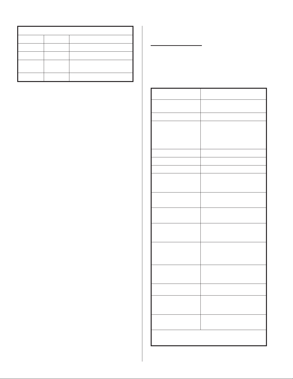
Manual drain rates of suspect units should be
checked using Figure #18 as reference times.
Figure #18
Manual Drain Times
CYL. SIZE
(SERIES)
500/600 2 minutes and 52 seconds ± 10 sec.
400 1 minute and 20 seconds ± 5 sec.
300 43 seconds ± 2 sec.
200 25 seconds ± 1 sec.
PROPER TIME (sec) TO DRAIN MANUALLY
FROM SEAM TO EMPTY
BEIGE BODY DRAIN VALVE
If nothing is working, check for 24 VAC output
from the stepdown transformer (see wiring diagram).
If there is no 24 VAC output, the transformer might
have been damaged if external controls were installed
and/or connected with the field-supplied fused
disconnect on. If this is the case, the transformer must
be replaced.
The conductivity of the water within the cylinder
must be controlled, in order for the humidifier to
function properly. The fill and drain rates must be
maintained. Filling too quickly can cause over-amping
and automatic shutdown or blown fuses. Filling too
slowly can cause insufficient steam output and
humidity levels. Water supply pressure should be
between 30 and 80 psig, ideally 55 to 60 psig.
Draining too slowly can cause over-concentration and
If time measurements are longer, repeat with
external drain disconnected (and draining into a pail)
to know if external drain is impeding flow.
Clogged strainer and/or clogged drain valve will
cause shortened cylinder life. But start by determining
what caused the strainer and/or drain valve to clog in
the first place.
Do not assume that if strainer and/or drain valve
are clogged that they are to blame. If the external
drain has been impeding flow, then waste
accumulates, resulting in a clogged strainer and/or
clogged drain which, in turn, results in shortened
cylinder life.
-15-
Page 19

Clean the drain valve; start with a fresh cylinder.
Then measure the manual drain time with and without
the external drain connected. Is the external drain
impeding flow? NORTEC recommends an open
external drain line. See Form #XX-161.
NHMC/NHP
The self-diagnostic system built into the NHMC is
continually checking the status of the electrical circuits
to the fill valve, drain valve, primary voltage contactor,
high water sensor and steam cylinder. The modulating
signals from external humidistats and reduced manual
capacity settings are taken into consideration. When
problem symptoms are found, the NHMC/NHP will
take self-corrective actions, if applicable. It will, if
necessary, respond by shutting itself down.
The NHMC/NHP communicates its findings to the
user by way of the unit’s status lamps and signals sent
to the terminal strip for optional external remote
indication. Even more directly, the NHMC has an
alphanumeric system message to the user via the
LCD (liquid crystal display).
de-energizing the contactor momentarily while it
drains.
Probable Cause(s):
1. Cylinder water is over-concentrated (too
conductive) due to restricted drain, short-cycling
by controls, supply water not within acceptable
limits (too conductive), improper fill rate, incorrect
cylinder being used.
2. Water level too high due to leaking fill valve,
excess condensate return from steam line.
Corrective Action:
1. Note water level.
2. Manually drain cylinder while checking drain rate
(refer to Figure #7 for proper drain times). If too
slow correct cause.
3. Turn unit back on and check the fill rate (1 - 1-1/2
inches per minute)
4. Once RH% set point is attained, monitor cycle
time.
All of this is summarized for each system message
in the following easy-to-follow format.
NHMC/NHP Explanation of System Messages and
Responses —- EPROM : 2.XXN
1. Maximal Level (Shown on NHMC LCD display
only)
Symptom(s) Diagnosed:
Water has reached the
top of the cylinder and activated the high water
sensor circuit. This is not an error or fault
diagnostic. Note: This is normal on start-up and
at end of cylinder life before Error 4 shows.
Probable Cause(s):
Normal on startup with a
new cylinder or a cylinder that has been
completely drained because of an extensive off
period. Can last for several hours until the water
in the cylinder has concentrated or the electrodes
can no longer provide rated capacity (or adjusted
capacity). Water level automatically rises to seek
out fresh electrode surface to meet the demand.
Unit Takes Self-Corrective Action:
Yes. It stops
the fill valve to prevent overfilling.
2. Excess Current - Error 1
Symptom(s) Diagnosed:
Current drawn on
monitored primary lead to cylinder has reached or
exceeded 125% of its rated amps. The unit will
have tried to self-correct prior to system shutdown
by draining water from the cylinder or
Response:
See Figure #2, NHMC/NHP System
Messages
3. No Current - Error 2
Symptom(s) Diagnosed:
Full cylinder (MAXIMAL
LEVEL) detected with no current draw sensed by
the electronics on monitored primary lead to
cylinder.
Probable Cause(s):
1. No current being drawn, specifically on the
monitored primary lead to the cylinder, or the
actual current not being sensed.
2. False detection of a full cylinder (water level within
inches of cylinder top) due to foaming,
wiring/connection problem, circuit board failure.
Corrective Action:
Check water level in cylinder.
1. If full (within 4" of top) disconnect white sensor
plug on cylinder, reset unit and check monitored
primary lead to cylinder for current with amp
clamp. If current present, determine why main
PCB does not sense the current. If no current,
present determine cause of primary voltage
interruption.
2. If not full disconnect white sensor plug on cylinder,
reset unit. If error 2 does not reoccur within two
minutes, cylinder was likely foaming and should be
flushed. If error 2 does reoccur within two
minutes, there is a problem with the high water
sensor PCB. If error 2 occurs with the high water
sensor PCB disconnected, there is a problem with
the main PCB.
-16-
Page 20

Response: See Figure #2, NHMC/NHP System
Messages
4. Max. Filling Time - Error 3
Symptom(s) Diagnosed:
Time dependent.
Neither Maximal Level (full cylinder) is detected,
nor is there enough current drawn to meet
capacity demand. Current monitored on primary
lead to cylinder is greater than zero and not
decreasing. The unit will have tried to self-correct
prior to system shutdown by pulse activating the
drain valve to possibly clear any debris holding the
drain valve open.
Probable Cause(s):
1. Steam line restriction causing back pressure.
displayed and the fill valve does not energize (green
LED must be illuminated), the main PCB is defective.
If Maximal level is displayed, a problem exists with
the cylinder or the high water sensor PCB. A voltage
of 85 VAC or greater across the orange wires of the
high water PCB ( one orange wire terminates at the
white sensor plug attached to the soldered pin of the
cylinder, the other terminates at one of the contactor
connections) will signal a full cylinder (Maximal
Level) to the main pcb. If this voltage does exist, the
problem is with the high water PCB, if not, the
problem is within the cylinder (can be caused by
cylinder being past end of life.
5. If not full, drain cylinder, reset unit, and check the
fill rate (refer to Figure #2 ). If the fill rate is
correct, back pressure is the likely cause and
should be rechecked.
2. Improper fill rate.
3. Leaking drain valve
4. Full cylinder not detected.
Unit Takes Self-Corrective Action:
Yes. It
pulse-activates the drain valve to possibly clear
any dirt. It retests. If the symptoms persist after
two attempts, it then responds as shown in Figure
#2.
Corrective Action:
1. Check for water leaking from drain. If present,
correct the drain valve deficiency (check for debris
holding drain coil plunges open).
2. Ensure the steam line, from the cylinder outlet to
the steam distributor (duct or blower pack), is
properly installed, to ensure back pressure is not
the case.
3. Check water level in cylinder.
4. If full reset unit and ensure there is a demand for
steam (the green LED on unit door will stay
illuminated. Maximal Level should be indicated on
the LCD display and both green and yellow LED is
on the unit door illuminate almost immediately. If
Maximal Level is not indicated, a problem exists
with the high water sensor circuitry.
a) Check wiring of the high water sensor PCB
(refer to unit wiring diagram).
Response:
See Figure #2, NHMC/NHP System
Messages.
5. Cylinder Spent - Error 4
Symptom(s) Diagnosed: Water level stays high,
cycling on and off Maximal Level (full cylinder),
without an increase in output/amp draw or
reaching demand.
Probable Cause(s):
1. Cylinder has reached end of life due to insulative
mineral coating on electrodes.
2. New cylinder start up with low incoming water
conductivity.
Corrective Action:
1. If the cylinder is not new, replace the cylinder
immediately. Within approximately three days, the
unit will shut itself down on Error 9 resulting in no
output instead of reduced output.
2. If the cylinder is new, the electronics will
differentiate cylinder spent from new cylinder start
up and the displayed error will discontinue without
a shutdown on Error 9.
Response:
See Figure #2, NHMC/NHP System
Messages.
6. No Current - Error 5
b) Check for amperage on all wires at the
cylinder, with an amp probe (amp clamp). If
amperage is not detected on all wires,
correct primary wiring deficiency. If
amperage is detected on all wires, proceed
to next step.
c) Place a jumper across 42 and 48 of main
PCB for five seconds. If Maximal Level is not
-17-
Symptom(s) Diagnosed:
Time dependent. No
current sensed by the electronics on the monitored
primary lead to the cylinder. The unit will have
tried to self correct prior to system shutdown by
pulse activating the drain valve, to possibly clear
any debris holding the drain valve open.
Probable Cause(s):
Page 21

1. No current being drawn on the monitored primary
lead to the cylinder, or the actual current is not
being sensed.
2. Water does not reach the electronics due to a
restricted water supply line or due to a constantly
open/leaking drain valve preventing a water level
increase.
3. High duct static pressure blowing back into the fill
cup (via steam line, empty cylinder) diverting the
fill cup water to the overflow.
c) If 24 VAC is not present, then check for 24
VAC across 6 and 14 on the PCB.
d) If 24 VAC is not present across 6 and 14 of
the PCB, then the problem is with the main
PCB.
e) If 24 VAC is present across 6 and 14 of the
PCB, then check for a break in the circuit to
the fill valve.
Unit Takes Self-Corrective Action:
Yes. It
pulse-activates the drain valve to possibly clear
any dirt holding the seal open. It re-tests. If
symptoms persist after two attempts, it then
responds as shown in Figure #2.
Corrective Action:
1. Check the water level in the cylinder.
2. If there is water in the cylinder (1/5 of a full
cylinder or more) check monitored primary lead to
the cylinder for current with an amp clamp.
a) If current is present with zero output
indicated on the display, the problem is with
the main PCB.
b) If no current is present determine the cause
of the primary voltage interruption.
3. If there is little or not water in the cylinder turn the
unit off and disconnect the steam line at the
cylinder. Reset the unit and monitor filling.
a) If unit fills and Error 5 does not reoccur, the
problem was likely caused by air flow through
the fill system and can be permanently
corrected by installing a U trap on the fill line
between the fill cup and the drain valve body.
Response:
See Figure #2, NHMC/NHP System
Messages.
7. Output Too Low - Error 6
Symptom(s) Diagnosed:
Time dependent.
Neither Maximal Level (full cylinder) is detected,
nor is there enough current drawn to meet
capacity demand. Current monitored on primary
lead to cylinder greater than zero but decreasing.
Unit Takes Self-Corrective Action:
Yes. It
pulse-activates the drain valve to possibly clear
any dirt holding the seal open. It re-tests. If
symptoms persist after two attempts, it then
responds as shown in Figure #2.
Probable Cause(s):
Corrective Action:
Response:
See Figure #2, NHMC/NHP System
Refer to Error 3.
Refer to Error 3.
Messages.
8. Electronic - Error 7 (NHMC only)
Symptom(s) Diagnosed:
The electronics of the
main PCB have diagnosed the main PCB as
defective.
b) If unit does not fill, then turn the unit off and
clean and check the drain valve (refer to
section on Mandatory Cleaning of the Drain
Valve in this manual) to ensure that there are
no obstructions or leaks in the drain valve
preventing it from holding water in the
cylinder, and check water inlet for
obstructions.
4. Turn unit back on and see if it will fill.
a) If unit still does not fill, then with the unit
turned on, check for 24 VAC across the fill
valve (there must be a call for humidity).
b) If 24 VAC is present, then the problem is with
the fill valve.
Probable Cause(s):
1. A spike in the primary power supply to the
humidifier, either high (surge) or low (brown out),
causing the electronics to experience a logic
glitch.
2. A problem with the main PCB.
Corrective Action:
1. Reset humidifier and monitor display. If Error 7
reoccurs within one minute of resetting the unit,
the problem is with the main PCB. If Error 7 is not
repeated, the primary power to the unit is suspect.
Response:
See Figure #2, NHMC System
Messages.
-18-
Page 22

9. Phase Interrupt - Error 8 (NHMC only)
NHB
Symptom(s) Diagnosed:
The 24 VAC to the main
PCB, across terminals 44 and 46 is interrupted.
Probable Cause(s):
a) A wiring problem leading to an interruption of
the 24 VAC to terminals 44 and 46 of the
main PCB.
b) A problem with the main PCB.
Corrective Action:
1. With the unit switched on, measure across
terminals 44 and 46 of the main PCB for 24 VAC.
If not present, find the cause of interruption. If
present, the problem is with the main PCB.
Response:
See Figure #2, NHMC System
Messages
10. Cyl. Lifespan End - Error 9
Symptom(s) Diagnosed:
The criteria for
diagnosing Cylinder Spent - Error 4 has expired
and cylinder has not been replaced. Humidifier
has shut down to avoid unsafe operation.
Probable Cause(s):
Refer to Error 4.
The NHB checks the status of the electrical
circuits to the fill valve, drain valve, primary voltage
contactor, high water sensor and steam cylinder. The
manual capacity setting, if reduced, is taken into
consideration. When problem symptoms are found,
the NHB will, if necessary, respond by shutting itself
down.
The NHB communicates its findings to the user by
way of the unit’s status lamps and a 24 Vac (maximum
100 mA maximum) signal sent to the terminal strip for
optional external remote indication.
The signal for remote indication comes in
response to the following symptoms. In each case,
the NHB shuts itself down. The green status lamp
goes off, but the yellow status lamp (and remote fault
relay) remain on.
NHB Explanation of Automatic Shutdowns
1. Excess Current
Symptom(s) Diagnosed:
Current in steam
cylinder increases beyond the fill off and
emergency drain on triggers. Current reaches
150% of FLA (i.e. 134% of fill off rated amps; i.e.
134% of amps on spec. label) for 1 second.
Corrective Action:
Response:
See Figure #2, NHMC/NHP System
Refer to Error 4.
Messages.
Troubleshooting Dual Cylinder Units
Double units, NHMC-150 and 200, are two circuits
in one cabinet sharing one LCD display. A ribbon
cable between the RS232 ports links the two circuits.
The left circuit is the master. [1] on the display means
left side. [2] on the display means right side.
Refer to double unit operation on in the NHMC
Installation and Operation Manual.
When a fault occurs on the right side of a double
unit, both sets of lamps (and remote relays) will come
on indicating that a fault has occurred. The left side
(master) will display its own faults as well.
The LCD will indicate which fault has occurred and
on which side of the unit, [1] or [2]. The side not
faulted will continue to operate as usual.
The side which has shut down on fault can be
treated as a single circuit using the same
troubleshooting guidelines as previously described.
Probable Cause(s):
Blocked drain due to blocked
cylinder strainer or blocked drain valve or blocked
external drain line. No power to drain valve at
emergency drain on trigger. Power remains on fill
valve at fill off trigger. Wrong steam cylinder (too
conductive). Wrong fill valve (orifice too big).
Wrong supply voltage (too high). Supply water too
conductive. Contained water too conductive.
100% softened supply water is often too
conductive. Measure conductivity and report
findings to factory if suspected. Mineral bridge
between electrodes.
Unit Takes Self-Corrective Action:
It has already
tried to control current with fill off and emergency
drain on triggers. It then responds as shown
below.
Response:
UNIT STATUS LAMPS REMOTE
UNIT
YELLOW GREEN 61-20
CONTACTOR
OFF ON OFF ON
INDICATION
(24 Vac to:)
“YELLOW”
-19-
Page 23

2. Max. Filling Time
Symptom(s) Diagnosed:
The fill valve has been
“on” for a longer time than is normally required for
non-zero current to flow between the electrodes or
for water level in the cylinder to reach the high
water sensor pin.
Probable Cause(s):
As pure steam is produced
from tap water, most minerals are drained by the
auto-adaptive control system. However, it is
inevitable that minerals will buildup on the
electrodes and strainer inside the steam cylinder.
It is unavoidable and the cylinder is intended to be
disposable.
Probable Cause(s): Blocked drain due to blocked
cylinder strainer or blocked drain valve preventing
water from entering the cylinder. Drain valve
leaking due to dirt in seal or powered by defective
main PC board or powered by wiring error. High
water sensor circuit not responding due to sensor
plug not connected or defective high water sensor
PC board or wiring error or defective main PC
board. Water supply rate too low or zero due to
too low pressure or line restriction or clogged
built-in strainer. Too low supply water
conductivity. DI (de-ionized) or RO (reverse
osmosis) supply water has almost no conductivity.
Measure conductivity and report findings to factory
if suspected.
Response:
UNIT STATUS LAMPS REMOTE
UNIT
CONTACTOR
OFF ON OFF ON
YELLOW GREEN 61-20
INDICATION
(24 Vac to:)
“YELLOW”
NHB Explanation of Symptoms Without Automatic
Shutdown
4. No Current But High Water Sensor On
Symptom(s) Diagnosed:
High water level in the
steam cylinder is detected, yet no current is
detected in the steam cylinder.
Probable Cause(s):
Sensor plug connected to
wrong cylinder pin. High water sensor PC board
defective (activates with no water). Main PC
board defective (activates high water circuit
without sensor PC board). Monitored leg of three
phase power supply is dead. Main PC board
defective (does not sense current when current is
present in monitored leg).
5. Cylinder Spent
Symptom(s) Diagnosed:
The high water sensor
circuit is activated. Other criteria are used to
distinguish cylinder spent from normal startup and
diagnose the steam cylinder as spent, as
previously described.
Unit Takes Self-Corrective Action:
The humidifier
continues to operate with gradually decreasing
capacity, giving the user notice by responding as
shown below.
Response :
UNIT STATUS LAMPS REMOTE
UNIT
CONTACTOR
ON ON ON ON
YELLOW GREEN 61-20
INDICATION
(24 Vac to:)
“YELLOW”
6. No Current But Humidistat Calling
Symptom(s) Diagnosed:
For a few minutes, no
current is detected in the steam cylinder, despite a
demand for humidity. (Current is not expected to
be zero when there is a demand for humidity.)
Probable Cause(s):
Drain valve is leaking, so
water never reaches the electrodes. Water supply
is obstructed. Contactor is not activated. Supply
water is “pure” without conductivity. Fill valve is
blocked. Fill valve is not being activated. Supply
water pressure is too low (less than 30 psig).
Wrong orifice in fill valve. High duct static
pressure blows back into the fill cup (via the steam
line and empty cylinder) diverting the fill water to
overflow. (Taking the steam hose off until some
water gets into the cylinder solves this.)
6. Output Too Low
Symptom(s) Diagnosed:
For a few minutes,
current does not increase in the steam cylinder,
despite the fill valve being activated. (Current is
expected to increase soon after the fill valve is
activated.)
Probable Cause(s):
Drain valve is partially open,
so fill rate maintains non-zero but non-increasing
current. Continual overflow because high water
sensor circuit did not respond to full cylinder.
Supply water insufficiently conductive. Fill valve is
partially restricted due to dirt, pinched supply line,
or wrong orifice. Steam supply line is obstructed
so back pressure causes continual overflow.
-20-
Page 24

Supply water pressure is too low (less than 30
psig).
7. Electronics
Symptom(s) Diagnosed:
is switched on, green status lamp does not come
on.
Probable Cause(s):
damaged. (Long life LED should never burn out.)
NHB electronic board assembly was damaged in
shipment or installation. Electronics need to be
replaced.
8. Yellow and Green Status Lamps Both On
Symptom(s) Diagnosed:
top of the cylinder and activated the high water
sensor circuit. Note: This is normal on startup
and at end of cylinder life.
Probable Cause(s):
cylinder. Can last for several hours until cylinder
reaches optimum contained water conductivity or
electrodes can no longer provide rated capacity
(or adjusted capacity). Water level automatically
rises to seek out fresh electrode surface to meet
the demand.
Unit Takes Self-Corrective Action:
the fill valve to prevent overfilling.
When on/off/drain switch
Green status lamp is
Water has reached the
Normal on startup with a new
Yes. It stops
USING THE WIRING DIAGRAM
humidistat (if present), terminals 84-85 and finally the
cabinet mounted on/off humidistat (if present). 24 Vac
arrives at the electronics’ terminals 10 (hot) and 6
(ground). A second “hot leg” takes a more direct route
to terminals 8, 18, 34, 38, 44 on the electronics via the
“on switch” and the door interlock switch in series.
The primary voltage circuit is what turns the water
in the cylinder to steam for humidification. The internal
primary fuses (if present) are followed by the primary
contactor(s). When the 24 Vac coil is powered, the
contactor “makes”. One primary leg is routed through
the core of the linear Hall Effect current sensing circuit
on the electronics, then it goes to the cylinder. The
high water sensor board has a primary voltage side.
One leg connects to the primary leg; one leg connects
to the short sensor pin in the top of the cylinder. A
potential, somewhat less than primary, is picked up by
the sensor at high water level, which “makes” the
red/black circuit on the low voltage side. This creates
a resistive loop across terminals 42-48 on the
electronics which stops the fill valve until water boils
down below the sensor pin.
Back at the electronics, the contactor receives its
“hot leg” from terminal 12. The fill receives its “hot leg”
from terminal 14. The drain receives its “hot leg” from
terminal 16. Unlike the contactor and fill, the drain
gets its “ground leg” directly from the transformer. It
does not depend on the air proving switch to activate.
The yellow and green unit status lamps are LED’s.
Polarity is important. Terminal 4 is positive dc supply.
Terminals 22 and 24 are switched dc grounds for
yellow and green respectively.
Fixed to the inside of each unit’s door is a wiring
diagram showing all of the internal (and most of the
external) wiring details. Additional external wiring
details can also be found with any electrical
accessories purchased from NORTEC.
The following is a detailed explanation of how the
NH humidifier (with and without options) operates.
Direct reference is made to the wiring diagram.
Reviewing the proper function in detail will make it
easier to troubleshoot if something goes wrong.
The wiring diagram details a 24 Vac control circuit
and a primary voltage circuit.
NHMC/NHP
A primary-to-24 Vac 75 VA transformer, tapped
from the primary, powers the 24 Vac control circuit.
One leg of the secondary is connected to ground and
terminals 6 and 46 on the electronics. The “hot leg”
finds its way to the electronics via the following in
series: the external on/off controls (if present),
terminals 8-10, the blower pack mounted on/off
NHB
A primary-to-24 Vac 75 VA transformer, tapped
from the primary, powers the 24 Vac control circuit.
One leg of the secondary is connected to ground and
terminal 6 on the electronics. The “hot leg” finds its
way to the electronics via the following in series: the
external on/off controls (if present), terminals 8-10, the
blower pack mounted on/off humidistat (if present),
terminals 84-85 and finally the cabinet mounted on/off
humidistat (if present). 24 Vac arrives at the
electronics’ terminals 10 (hot) and 6 (ground). An
onboard 3.15 amp glass fuse protects the circuit. A
second “hot leg” takes a more direct route to terminals
8 and 18 on the electronics via the “on switch” and the
door interlock switch in series.
The primary voltage circuit is what turns the water
in the cylinder to steam for humidification. The internal
primary fuses (if present) are followed by the primary
contactor(s). When the 24 Vac coil is powered, the
contactor “makes”. One primary leg is routed through
the core of the linear Hall Effect current sensing circuit
on the electronics, then it goes to the cylinder. The
-21-
Page 25

high water sensor board has a primary voltage side.
One leg connects to the primary leg; one leg connects
to the short sensor pin in the top of the cylinder. A
potential, somewhat less than primary, is picked up by
the sensor at high water level, which “makes” the
red/black circuit on the low voltage side. This creates
a resistive loop across terminals 2-4 on the electronics
which stops the fill valve until water boils down below
the sensor pin.
Back at the electronics, the contactor receives its
“hot leg” from terminal 12. The fill receives its “hot leg”
from terminal 14. The drain receives its “hot leg” from
terminal 16. Unlike the contactor and fill, the drain
gets its “ground leg” directly from the transformer. It
does not depend on the air proving switch to activate.
The yellow and green status lamps are LED’s.
Polarity is important. Terminal 26 is positive dc
supply. Terminal 22 and 24 are switched dc grounds
for yellow and green respectively.
BLOWER PACKS
An optional blower pack (BP), if present, gets its
primary voltage from inside the humidifier. This way,
only one external power source has to be connected to
the equipment.
TERMS USED
RATED AMPS: Refers to amps listed on the
humidifier specification label.
SHORT CYCLING: When the ‘on time’ of the
humidifier is less than ten minutes upon a call for
humidity. To correct short cycling, all humidifiers have
a capacity adjustment which allows the output of the
humidifier to be reduced as low as 20% of rated
output, thus extending the ‘on time’ required to
maintain output.
FOAMING: The phenomenon which can occur in
water when the impurities, already in the water, reach
an excess concentration as result of boiling away pure
water and the continued boiling action agitating the
contained water. The humidifier electronics are
designed to prevent this occurrence although in
extreme cases water will foam with little concentration,
making it necessary to have the drain time of the
water, contained in the cylinder, increased. Foaming
is normally caused by short cycling, a restricted drain,
or back pressure. The foam, generated in these
instances, is conductive and may lead to a false full
cylinder indication if the level of the foam approaches
the top of the cylinder.
BACK PRESSURE: Restriction of steam flow
caused by long steam runs, improperly sloped steam
lines, elbows changing the direction of the steam flow
from horizontal to vertical without a drain leg, any
plumbing detail allowing the accumulation of
condensate, undersized steam line, improper steam
distributor, downward air flow onto the distributor
creating excess static pressure at the steam outlets or
high static pressure ducts (not probable). To
overcome excess static pressure in the duct, a fill cup
extension kit should be used. In downflow
applications, a downflow distributor should be used but
in some cases the fill cup extension will also be
required.
RESET UNIT (HUMIDIFIER): To reset the
humidifier, the on/off/drain switch at the front of the
humidifier should be switched to the off position for a
minimum of five seconds and then switched back to
the on position.
MONITORED LEG: Refers to the primary wire, to
the cylinder, which loops through the current sensing
device on the main pcb. This wire is terminated at the
red cylinder plug at the cylinder. Units with six primary
wires to the cylinder will monitor only one of the two
wires, terminating with red plugs.
-22-
Page 26

OPTIONAL BLOWER PACK ( BUILT-ON OR REMOTE )
TRANSFORMER
( IF REQUIRED )
INTERNAL
EXTERNAL
3A
FUSE
S
FAN
RELAY
TWO SPEED SWITCH
24 V
THERMODISC ( N.O. )
COIL
T
HIGH
LOW
8283838484
RESETABLE
THERMODISC ( N.C. )
FAN
OPTIONAL BLOWER PACK
MOUNTED ON/OFF HUMIDISTAT
85
or JUMPER
T
BLOWER
PACK
TERMINAL
BLOCKS
EXTERNAL
INTERNAL
TRANSFORMER
3PHASE
CONNECTION
OPTIONAL
INTERNAL
FUSE BLOCK
(NHB 050
OR LARGER)
DEDICATED
DISCONNECT
BY OTHERS
SSS
GROUND
SSS
CLAMP
L1L2L3
xxx
PRI. TERMINAL
BLOCK OR
OPTIONAL FUSE
BLOCK ( NHB
030 OR SMALLER)
STEP DOWN
TRANSFORMER
SSS
24 V
COIL
CONTACTOR(S)
24 V
COIL
3
241
G
DOOR
INTERLOCK
SWITCH
HIGH
WATER
SENSOR
RED WIRE
JUMPER OR
ON/OFF
CONTROLS
IN SERIES
3A
FUSE
S
FILL
VALVE
DRAIN
VALVE
2
10
8
MAIN SWITCH
1/2
2/2
24 V
COIL
24 V
COIL
6 8
4
818182
1/3
1/1
2/3
2/1
10
0N
OFF
DRAIN
14 12 16
85
STATUS
INDICATOR
LED's
_
26 22 24
OPTIONAL REMOTE
467
8
Y
G
_
YELLOW
INDICATOR
Y
2061
20
18
INTERNAL
EXTERNAL
Si 1
S
S
Si 2
NHB MAIN BOARD
Si 1= 3.15A FUSE
Si 2= 3.15A FUSE
Sx % = MANUAL CAPACITY ADJUST
Sx %
NHB HUMIDIFIER
w OR w/o OPTIONAL BLOWER PACK
(BUILT-ON OR REMOTE)
WIRING DIAGRAM NO. 92-0-A REV. 9
-23-
Page 27

OPTIONAL BLOWER PACK ( BUILT-ON OR REMOTE )
TRANSFORMER
( IF REQUIRED )
INTERNAL
EXTERNAL
3A
FUSE
S
FAN
RELAY
TWO SPEED SWITCH
24 V
THERMODISC ( N.O. )
COIL
T
HIGH
LOW
84
85
RESETABLE
THERMODISC ( N.C. )
FAN
OPTIONAL BLOWER PACK
MOUNTED ON/OFF HUMIDISTAT
or JUMPER
T
BLOWER
PACK
TERMINAL
BLOCKS
EXTERNAL
INTERNAL
TRANSFORMER
3 PHASE
CONNECTION
OPTIONAL
INTERNAL
FUSE BLOCK
(NHMC 050
OR LARGER)
DEDICATED
DISCONNECT
BY OTHERS
SSS
xxx
SSS
SSS
GROUND
CLAMP
L1L2L3
PRI. TERMINAL
BLOCK OR
OPTIONAL FUSE
BLOCK ( NHMC
030 OR SMALLER)
STEP DOWN
TRANSFORMER
24 V
COIL
CONTACTOR(S)
24 V
COIL
4
3
1
2
JUMPER OR
ON/OFF
CONTROLS
IN SERIES
G
3A
FUSE
24 V
DOOR
INTERLOCK
SWITCH
HIGH
WATER
SENSOR
RED WIRE
44 46 48 42
K3
K2
38 34 36 40
MAIN SWITCH
S
FILL
VALVE
DRAIN
VALVE
8
10
81818282838384
0N
1/3
1/2
OFF
1/1
DRAIN
2/3
2/2
2/1
24 V
COIL
24 V
COIL
10
6 8
14 12 16 18 2032 30 28 2642224
S
S
Si 1
Si 2
X3
Si 1= 3.15A FUSE
Si 2= 3.15A FUSE
OPTIONAL
MODULATION
SEE EX. W.D.
85
32 30 28 26
500 OHM
2WATT
RESISTOR
STATUS
INDICATOR
LED's
Y
G
G
__
NHMC MAIN BOARD
c/w PIGGY BACK BOARD
X2 X4
LCD DISPLAY
OPTIONAL REMOTE
YELLOW, GREEN
AND RED
INDICATORS
Y
R
G
366340622061
INTERNAL
EXTERNAL
OPTIONAL LCD/KEYPAD DISPLAY
RS 232
NHMC HUMIDIFIER
w OR w/o OPTIONAL BLOWER PACK
(BUILT-ON OR REMOTE)
WIRING DIAGRAM NO. 94-0-A REV. 10
-24-
Page 28

TRANSFORMER
( IF REQUIRED )
OPTIONAL BLOWER PACK ( BUILT-ON OR REMOTE )
3A
FUSE
RELAY
INTERNAL
EXTERNAL
S
FAN
TWO SPEED SWITCH
24 V
THERMODISC ( N.O. )
COIL
T
HIGH
LOW
84
85
RESETABLE
THERMODISC ( N.C. )
FAN
OPTIONAL BLOWER PACK
MOUNTED ON/OFF HUMIDISTAT
or JUMPER
T
BLOWER
PACK
TERMINAL
BLOCKS
EXTERNAL
INTERNAL
TRANSFORMER
3 PHASE
CONNECTION
OPTIONAL
INTERNAL
FUSE BLOCK
(NHP 050
OR LARGER)
DEDICATED
DISCONNECT
BY OTHERS
SSS
SSS
GROUND
L1L2L3
xxx
PRI. TERMINAL
BLOCK OR
OPTIONAL FUSE
BLOCK ( NHP
030 OR SMALLER)
STEP DOWN
TRANSFORMER
SSS
24 V
COIL
CONTACTOR(S)
24 V
COIL
4
CLAMP
DOOR
INTERLOCK
SWITCH
HIGH
WATER
SENSOR
132
44 46 48 42
38 34 36 40
G
3A
FUSE
RED WIRE
JUMPER OR
ON/OFF
CONTROLS
IN SERIES
8
MAIN SWITCH
S
1/2
2/2
FILL
VALVE
DRAIN
VALVE
6 8
Si 2
Si 1= 3.15A FUSE
Si 2= 3.15A FUSE
Sx % = MANUAL CAP. ADJUST
ts = DRAIN FACTOR ADJUST
10
81818282838384
0N
1/3
OFF
1/1
DRAIN
2/3
2/1
24 V
COIL
24 V
COIL
10
14 12 16 18 2032 30 28 2642224
S
S
Si 1
X2X3
OPTIONAL
MODULATION
SEE EX. W.D.
85
32 30 28 26
STATUS
INDICATOR
LED's
Y
G
__
Sx %
NHP MAIN BOARD
c/w PIGGY BACK BOARD
OPTIONAL CAPACITY OUTPUT INDICATOR
ts
110
OPTIONAL REMOTE
YELLOW
INDICATOR
Y
CHECK
366340622061
INTERNAL
EXTERNAL
NHP HUMIDIFIER
w OR w/o OPTIONAL BLOWER PACK
(BUILT-ON OR REMOTE)
WIRING DIAGRAM NO. 95-0-A REV. 8
-25-
Page 29

NH Electric Steam Humidifier
Humidifier Mandatory Pre Start-up Checklist (p. 1 of 1)
Unit Serial #:________ # of humidifiers: _____ Tag:_____________
Unit type:
Voltage: _____V/___ph Steam output: ____lbs/hr
Customer/Job:_______________ Address: __________________________________
Inspected by: ________________ Date of inspection:____/____/____
_____________________________________________________________________________________________
WATER QUALITY:
Well water r City water r Softened wate r RO / DI water r
Conductivity: _______mhmos Hardness: _____ gr.
HUMIDIFIER MOUNTING:
Clearances around the unit Acceptable Obstruction
- Front (door opens freely?) 3ft min ____________________
- Top (steam lines) 2ft min ____________________
- Bottom (fill, drain, controls) 2ft min ____________________
- Right (main pwr) 2ft min ____________________
STEAM LINES: CONDENSATE LINES:
- Slope up 2” per 12” r - Slopped back to drain r
- Slope down ½” per 12” r - Trapped 2” more than static duct pressure r
- Traps r - Size _______
- Insulated
- Length/Size _____/_______ - ________% Vertical _______% Horizontal
r - Stainless steel r or plastic r
- 90 deg. elbows
- Can condensate be trapped anywhere in the steam line? Yes
r qty: ____ - 45 deg. Elbowsr qty: ____
r no r
WATER LINES:
- ½” at max 4ft from the unit r - 3/8” connection at fill r
- water pressure: 30-80psig r - PVC r - Stainless steel r
DRAIN LINES:
- Air gap located within 3ft of the unit r - Slopped to drain r - Size:________
CYLINDER:
- Cylinder properly installed and sitting upright
WIRING:
- No loose wires around the unit or on the PC board? yes r no r
CONTROLS:
- High limit: r___________________ - Air proving: r___________________
- Mod controller:
Installed Location / Wiring /Setting Installed Location / Wiring /Setting
r___________________ - Other: r___________________
POWER:
- Voltage, amperage rating and fuse correspond to Spec Label r
- Disconnect switch located close to humidifier r
-26-
Page 30

NH Electric Steam Humidifier
Humidifier Mandatory Start-up Checklist & Quick Reference (p. 1 of 1)
Unit Serial #: ________ # of humidifiers: _____ Tag:_____________
Unit type:
Voltage: _____V/___ph Steam output: ____lbs./hr
Customer/Job:_______________ Address: ___________________________________
Start-up by: _____________ Date of start-up:___/___/___
______________________________________________________________________________________________
1. PRELIMINARY:
- Pre-start-up checklist completed? yesr nor
If no, return to Pre-Start-up Checklist before going on with start-up procedure.
2. START-UP PROCEDURE:
The prerequisites for getting power and water into the steam cylinder are as follows:
- check that main breaker is on and power is at the unit.
- check that main water shut-off valve is open.
- on/off/drain switch must be switched on.
- control circuit 8-10 must be made.
- modulation humidistat, if present, must be calling.
- control circuit 82-83 must be made.
- control circuit 84-85 must be made.
- cabinet mounted humidistat, if present, must be calling.
- door interlock switch must be made (interlock switch can be pulled out to operate unit).
The unit will undergo a self-test (P and MC models only) to ensure integrity of all the components:
- Lamp green (observe light energize)
- Lamp yellow (observe light energize)
- Contact relay 1 (24V to 61-20 for rem. yellow)
- Drain (sound and 24 volt at solenoid)
- Fill (24 volt at fill solenoid)
- Contactor (listen to contact pulling in) (Unit must be calling).
- Contact relay 2 (24V to 63-36 for rem. red)
- Contact relay 3 (24V to 61-20 for rem. green)
- Internal test (Test completed)
- Green and yellow blink together to show test passed
It will then start filling the cylinder and begins normal operation. Most water does not contain enough
conductivity for full boil on initial start-up. Units will need to concentrate the water over a time period
(hours to days). During this process both lights are on.
Remarks:
_______________________________________________________________________________________
_____________________________________________________________________________________
-27-
Page 31

NH Electric Steam Humidifier
Periodic Maintenance Checklist & Quick Reference (p. 1 of 2)
Unit Serial #: ________ # of humidifiers: _____ Tag:_____________
Unit type:
Voltage: _____V/___ph Steam output: ____lbs./hr
Customer/Job:_______________ Address: ___________________________________
Maintenance by: _____________ Date of maintenance:___/___/___
______________________________________________________________________________
WHEN TO REPLACE THE CYLINDER:
NHMC light indication and LCD display:
1.Cylinder spent error 4 with Yellow and Green lights on
2.Cyl. Lifespan error 9 with Yellow on and Green off
NHP light indication:
1.Yellow flashing and Green on (unit still working, might be initial start-up fill)
2.Yellow flashing and Green off (unit shut down)
NHB light indication:
1.NHB Yellow on
CYLINDER REPLACEMENT PROCEDURE:
1.Turn off water supply to unit.
2.Activate drain switch to completely empty water content (less than 10 min.)
3.When drained, put switch back to the off position.
4.Also open the main electrical disconnect switch and open plumbing door using the key.
5.Remove the cylinder plugs by pulling vertically. The plugs are press-fitted over the electrode pins
protruding from the top of the cylinder.
6.Using a slot screwdriver, loosen the steam hose clamp(s) and pull steam hose off the cylinder
vertically.
7.Using a small slotted screwdriver, depress tab on the re-usable tie wrap, if present, around the
middle of the cylinder. This will loosen the tie wrap to come apart for re-use later on.
8.The cylinder is now ready to be lifted out of the unit.
CAUTION: Cylinder and any un-drained water might still be HOT.
9.Always clean the drain valve before installing a new cylinder. (see further below)
10.Remove the used cylinder and replace by a new one. Do not re-use cylinder.
MANDATORY CLEANING OF THE DRAIN VALVE
1.Note that ring terminal for drain valve green ground wire is sandwiched between drain valve body
and drain pan.
2.Remove two screws securing drain valve body to drain pan. Disconnect the two slip-on terminals
from the two tabs on the (24VAC) drain valve coil.
3.Remove hose clip and hose connection from drain valve body.
4.Drain valve assembly is now free to be taken to a sink for disassembly and cleaning.
Important: Tapered end of spring must be installed toward the solenoid.
5.Clean out the end of the hose, and then reconnect it to the drain valve body with the clamp.
6.Fit mounting screws through drain valve body, one through ring terminal on green ground wire.
WARNING: To prevent the possibility of electrical shock the green ground wire must be reinstalled
before power is restored. Push the two slip-on terminals back onto the two tabs on the coil. The
terminals, although not identical, are reversible.ox. 10 seconds).
-28-
Page 32

NH Electric Steam Humidifier
Periodic Maintenance Checklist & Quick Reference (p. 2 of 2)
Unit Serial #: ________ # of humidifiers: _____ Tag:_____________
Unit type:
Voltage: _____V/___ph Steam output: ____lbs./hr
Customer/Job:_______________ Address: ___________________________________
Maintenance by: _____________ Date of maintenance:___/___/___
_____________________________________________________________________________
HOW TO INSTALL THE REPLACEMENT CYLINDER
1.Reverse procedure should be followed to install new cylinder. Main disconnect is to be left open
until cylinder is completely installed and reconnected.
2.Ensure that the re-usable tie wrap and mounting brackets within the unit secure the cylinder
properly.
3.The cylinder plug wires are colour-coded in accordance with coloured dots beside the electrode pins
on top of the cylinder.
4.This colour coding must be adhered to when replacing cylinder plugs on pins.
5.With cylinders having six primary voltage cylinder plugs, it should be noted that there are two of
each colour.
6.Care must be taken so that cylinder leads of the same color are always directly opposite each other
as indicated by the dot formation on the top of the cylinder.
7.The white cylinder plug on all units is for the high water sensor electrode, which always goes on the
single pin surrounded by a plastic shoulder.
8.Ensure that cylinder plugs fit snugly on the pins.
9.If cylinder plugs become loose, it is best to obtain a new replacement plug. Consult factory.
EXTENDED SHUTDOWN:
1.Before disconnecting power to the humidifier for a period of extended shutdown, ALWAYS DRAIN
the cylinder first.
2.Do NOT leave the switch in the DRAIN position indefinitely as the drain coil could burn out. Leave
the switch in the OFF position and “open” the main external fused disconnect to stop power to the
humidifier.
3.Close the shut off valve in the water supply line feeding the humidifier. Lock the cabinet door(s) to
prevent unauthorized tampering. All doors are factory supplied with keyed locks.
DO NOT LEAVE KEY IN LOCK. ACCESS SHOULD BE LIMITED TO AUTHORIZED PERSONNEL
ONLY.
4.NHMC 3 day drain: As long as the NHMC is powered, it will automatically drain the cylinder when
there has not been a call for humidity for an extended period of time.
5.The cylinder will remain empty until there is a call for humidity at which time the fill valve will open
and refill the cylinder.
This feature will reduce the possibility of corrosion of the electrodes and the possible accumulation of
algae and bacteria growing in the cylinder.
Remarks:
_______________________________________________________________________________________
_______________________________________________________________________________________
-29-
Page 33

/550-600/3
/440-480/3
/220-240/3
/208/3
/550-600/3
/440-480/3
/220-240/3
/208/3
/550-600/3
/440-480/3
/220-240/3
/208/3
/550-600/3
/440-480/3
/220-240/3
/208/3
/550-600/3
/440-480/3
/220-240/3
/208/3
/550-600/3
/440-480/3
030 050 075 100 150 200
SINGLE PHASE THREE PHASE
005 010 020 020
/220-240/3
/208/3
/550-600/3
/440-480/3
/220-240/3
/208/3
/550-600/1
/440-480/1
/347/1
/277/1
/220-240/1
/208/1
/550-600/1
/440-480/1
/347/1
/277/1
/220-240/1
/208/1
/110-120/1
VOLTS/PH
P/N
NORTEC
MODEL
ELECTRICAL REPLACEMENT PARTS FOR NHB/NHP/NHMC MODELS
DESCRIPTION
NO.
ITEM
3P 150A 132-3028 11 11 1
3P 310A 132-3030 11 11
(PRIMARY VOLTAGE) 3P 95A 132-3027 1 1 1111111111 11 11 11 1
1 TERMINAL BLOCK 2P 95A 132-3001 1 1 1 1 1 1 1 1 1 1 1 1 1
2P JJS 142-3189 1 1 1 1 1 1
OPTIONAL PRIMARY VOLT. 2P JJN 142-3183 1 1 1 1 1 1 1
FUSEBLOCK 3P JJN 142-3184 1 1 1 1 2 2 2 2 2 2 4 4 4 4
(not shown) 3P JJS 142-3186 11 11 11 11 21 22 42
60A JJN 142-3176 6 6 12 12
OPTIONAL PRIMARY VOLT. 40A JJS 142-3160 2 2 2 2 2 2 3 3 3 3 3 3 3 3 6 3 6 6 12 6
INTERNAL FUSE 40A JJN 142-3173 2 2 2 2 2 2 2 3 3 3 3 6 6
(not shown) 45A JJN 142-3174 66 1212
3P 40 A 132-3014 1 1 1 1 1 2 2 1 1 4 4 2 2
3P 63A 132-3015 22 44
CONTACTOR c/w 24V COIL 3P 30A 132-3013 1 1 1 1 1 1 2211 1 2 2 4
4 PRIMARY VOLTAGE 2P 30A 145-3013 1 1 1 1 1 1 1 1 1 1
PC BOARD ASSLY. 147-4994 1 1 1 1 1 1 1 1 1 1 1 1 1 1 11111111111111111122222222
5 HIGH WATER SENSOR 147-4998 1
220-240V 132-3230 1 1 1111122
277V 132-3277 1 1
347V 132-3347 1 1
380V 132-3380
416V 132-3417
440-480V 132-3460 1 11111122
550-600V 132-3575 1 11111122
TRANSFORMER - 75 VA 208V 132-3208 1 1 1111122
6 PRIMARY TO 24 V 110-120V 142-3110 1
NHMC 145-3008 3 3 3 3 3 3 3 3 3 3 3 3 3 3 3 33333333333333333366666666
NHP 135-9521A 1 1 1 1 1 1 1
NHP 135-9521B 1 1 1 1 1 1 1 1 1111111111
NHP 135-9521C 1111111122222222
NHMC 135-9520 1 1 1 1 1 1 1 1 1 1 1 1 1 1 11111111111111111122222222
TERMINAL STRIP NHP 145-3008 3 3 3 3 3 3 3 3 3 3 3 3 3 3 3 33333333333333333366666666
7 PC BOARD NHB 145-3008 2 2 2 2 2 2 2 2 2 2 2 2 2 2 2 22222222222222222244444444
8 MAIN PC BOARD NHB 135-9512 1 1 1 1 1 1 1 1 1 1 1 1 1 1 1 11111111111111111122222222
9 ON/OFF DRAIN SWITCH 145-3001 1 1 1 1 1 1 1 1 1 1 1 1 1 1 1 11111111111111111122222222
10 INDICATOR LAMP GREEN 135-3027 1 1 1 1 1 1 1 1 1 1 1 1 1 1 1 11111111111111111122222222
Page 34

-31-
Page 35

/550-600/3
/440-480/3
/220-240/3
/208/3
/550-600/3
/440-480/3
/220-240/3
/208/3
/550-600/3
1111111 1
1111111 1
/440-480/3
/220-240/3
/208/3
/550-600/3
/440-480/3
/220-240/3
/208/3
/550-600/3
/440-480/3
/220-240/3
/208/3
/550-600/3
1111111111111111111 1
1111111111111111111 1
/440-480/3
030 050 075 100 150 200
/220-240/3
/208/3
/550-600/3
/440-480/3
/220-240/3
/208/3
/550-600/1
/440-480/1
/347/1
/277/1
/220-240/1
/208/1
/550-600/1
/440-480/1
/347/1
SINGLE PHASE THREE PHASE
/277/1
/220-240/1
/208/1
/110-120/1
1 111111111111111111111111111111112222222 2
1 111111111111111111111111111111111111111 1
1 111111111111111111111111111111111111111 1
1 111111111111111111111111111111111111111 1
1 111111111111111111111111111111111111111 1
1 111111111111111111111111111111111111111 1
1 111111111111111111111111111111111111111 1
1 111111111111111111111111111111112222222 2
1 111111111111111111111111111111112222222 2
1 111111111111111111111111111111112222222 2
1 111111111111111111111111111111112222222 2
1 111111111111111111111111111111112222222 2
1 111111111111111111111111111111112222222 2
1 111111111111111111111111111111112222222 2
1 111111111111111111111111111111111111111 1
1 111111111111111111111111111111111111111 1
1 111111111111111111111111111111111111111 1
1 111111111111111111111111111111112222222 2
1 11111111111111111111111111111111
1 11111111111111111111111111111111
1 111111111111111111111111111111112222222 2
1 111111111111111111111111111111112222222 2
1 11111111111111111111
005 010 020 020
VOLTS/PH
1 11111111111111111111
P/N
NORTEC
MODEL
ELECTRICAL REPLACEMENT PARTS FOR NHB/NHP/NHMC MODELS
DESCRIPTION
NO.
ITEM
135-3028
INDICATOR LAMP YELLOW
11
135-9721
135-9708
PC OUTPUT METER BOARD NHP
LCD PC BOARD C/W CABLE NHMC
12
145-4402
145-4403
OUTPUT LED MET ER ASSLY NHP
LCD KEYPAD ASSLY NHMC
13
135-1045
135-1046
PLASTIC FRAME NHP/NHMC
BRACE NHP/NHMC
14
145-3003
Consult Factory
3.15A FUSE PC BOARD (SI2)
500 mA FUSE PC BOARD (SI1) NHB
15
185-3101
185-3102
145-3912
145-3905
5 PT. L.V. CONTROL ST RIP NHP/NHMC
12 PT. L.V. CONTROL STRIP NHP/NHMC
132-3020
GROUND CLAMP
17
LOCK AND 1 KEY
18
145-3905
145-3904
Consult Factory
1A FUSE PC BOARD (SI1) NHP/NHMC
4 PT. L.V. CONTROL ST RIP NHB
5 PT. L.V. CONTROL ST RIP NHB
16
145-1003
Consult Factory
Consult Factory
NHB
KEY FOR LOCK
3AMPFUSE-INLINE
USER INTERFACE PANEL NHB
19
20
21
147-3002
Consult Factory
Consult Factory
NHP/NHMC
NHP/NHMC
TERMINAL BLOCK FOR
OPTIONAL BLOWER PACK23RELAY NHB/NHP
22
145-3020
(NOT SHOWN)24ELECTRICAL DOOR
145-7451
145-7651
145-7652
145-7452
ELECTRICAL SIDE COVER
25
Page 36

-33-
Page 37

/550-600/3
/440-480/3
/220-240/3
/208/3
/550-600/3
/440-480/3
/220-240/3
/208/3
/550-600/3
/440-480/3
/220-240/3
/208/3
/550-600/3
/440-480/3
/220-240/3
/208/3
/550-600/3
/440-480/3
/220-240/3
/208/3
/550-600/3
/440-480/3
030 050 075 100 150 200
/220-240/3
/208/3
/550-600/3
/440-480/3
/220-240/3
/208/3
/550-600/1
/440-480/1
/347/1
/277/1
/220-240/1
/208/1
/550-600/1
/440-480/1
/347/1
SINGLE PHASE THREE PHASE
/277/1
/220-240/1
/208/1
005 010 020 020
/110-120/1
VOLTS/PH
1 1111111111111111111111111111111122222222
2 2222222222222222222222222222222244444444
1 1111111111111111111111111111111122222222
1 1111111111111111111111111111111122222222
1 1111111111111111111111111111111122222222
1 1111111111111111111111111111111122222222
1 1111111111111111111111111111111122222222
1 1111111111111111111111111111111122222222
1 1111111111111111111111111111111122222222
1 1111111111111111111111111111111122222222
1 1111111111111111111111111111111122222222
1 1111111111111111111111111111111122222222
1 1111111111111111111111111111111122222222
1 1111111111111111111111111111111122222222
1 1111111111111111111111111111111122222222
P/N
NORTEC
MODEL
PLUMBING REPLACEMENT PARTS FOR NHB/NHP/NHMC MODELS
DESCRIPTION
NO.
ITEM
CONSULT
TO ORDER REPLACEMENT CYLINDERS QUOTE THE 3-DIGIT
NUMBER ON THE CYL. BEING REPLACED OR QUOTE THE
FACTORY
UNIT SERIAL NUMBER/MOBEL/VOLTAGE FROM THE SPEC.
50
145-5000
145-5004
151-3003
151-3005
131-3244
135-3017
135-3032
135-3037
SMALL 1 11111111111111111111
LARGE 11111111111111111111
005-020 1 1 111111111111111
025-030 1111
050-075 11111111 2222
100 1111 2222
REUSABLE TIE-WRAP
FILL VALVE ASSLY.
LABEL
51
(INCLUDING MOUNTING FLANG E)
52
FILL VALVE GASKET
53
149-5072
FILL VALVE SCREWS
BRASS FITTING & WASHER
54
55
145-6130
3/8" STRAIGHT COMP. FTG.
56
132-8850
FILL CUP FILL HOSE
57
145-6000
132-6003
DRAIN VALVE - 3 PIECE ASSLY
64a
132-6002
NO COIL
DRAIN VALVE COIL ASSLY
(ASCO)
64b
135-3002
145-8014
132-8860
FILL CUP ELBOW
62
132-8860
FILL CUP DRAIN HOUSE
FILL CUP OVERFLOW HOSE
63
(SPECIFY LENGTH)64DRAIN VALVE ASSLY
C/W 24V COIL
135-1030
135-1035
135-1034
(SPECIFIY LENGTH)
FILL CUP
FILL CUP COVER
FILL CUP SPLASH DIVERTER
FILL CUP OUTLET GROMMET
59
60
58
61
Page 38

/550-600/3
/440-480/3
/220-240/3
/208/3
/550-600/3
/440-480/3
/220-240/3
/208/3
/550-600/3
11111111
/440-480/3
/220-240/3
/208/3
/550-600/3
/440-480/3
/220-240/3
/208/3
/550-600/3
/440-480/3
/220-240/3
/208/3
/550-600/3
11111111111122222222
111111111111
/440-480/3
/220-240/3
/208/3
/550-600/3
/440-480/3
/220-240/3
/208/3
/550-600/1
/440-480/1
/347/1
/277/1
/220-240/1
/208/1
/550-600/1
/440-480/1
/347/1
SINGLE PHASE THREE PHASE
/220-240/1
/277/1
010 020 020 030 050 075 100 150 200
/208/1
/110-120/1
1 1111111111111111111111111111111122222222
2 2222222222222222222222222222222244444444
1 1111111111111111111111111111111122222222
1 1111111111111111111111111111111122222222
2 2222222222222222222222222222222244444444
1 1111111111111111111111111111111122222222
005
VOLTS/PH
1 1111111111111111111111111111111122222222
1 1111111111111111111111111111111111111111
1 1111111111111111111111111111111111111111
1 11111111111111111111
1 11111111111111111111
P/N
NORTEC
MODEL
PLUMBING REPLACEMENT PARTS FOR NHB/NHP/NHMC MODELS
DESCRIPTION
NO.
ITEM
132-6004
DRAIN VALVE O-RING
(not shown)65DRAIN VALVE MOUNTING
145-5002
SCREW66DRAIN CANAL - RECTANGULAR
132-1218
132-1220
DRAIN CANAL GASKET - RECT.
67
145-5002
DRAIN CANAL
MOUNTING SCREW69DRAIN PAN OVERFLOW FTG.
68
132-880940
(IF UNIT HAS BLOWER PACK)7024V DOOR INTERLOCK
132-3091
SWITCH71SENSOR PLUG
135-4012B
135-4012Y
135-4012R
RED 1 1111111111111111111122112211 214422 42
YELLOW 1111111122112211 214422 42
CYLINDER PLUG
132-4264
132-7265
BLACK 22 44
YELLOW 22 44
CYLINDER "SUPER" PLUG
C/W 8AWG WIRE
135-4012W
WHITE 1 1111111111111111111111111111111122222222
BLACK 1 1111111111111111111122112211 214422 42
10AWG SPRING LOADED
72
132-8820
132-8810
132-4266
RED 22 44
3/4"NOM. 1 111111111111111111111
1-1/2" NOM. 1111111111111111111
STEAM HOSE
(SPECIFY LENGTH, NOT SHOWN)
73
185-3101
132-8840
3/8"NOM. 1 1111111111111111111111111111111122222222
CONDENSATE HOSE
(SPECIFY LENGTH, NOT SHOWN)
LOCK AND 1 KEY
75
74
185-3102
KEY FOR LOCK
76
145-7654
145-7454
PLUMBING DOOR
77
145-7020
145-7022
MOUNTING BRACKET
78
145-7023
Page 39

LIMITED WARRANTY
NORTEC INDUSTRIES INCORPORATED and/or NORTEC AIR
CONDITIONING INDUSTRIES LIMITED (hereinafter collectively referred to as THE
COMPANY), warrant for a period of two years from date of shipment, that THE
COMPANY’s manufactured and assembled products, not otherwise expressly
warranted (with the exception of the cylinder) are free from defects in material and
workmanship. No warranty is made against corrosion, deterioration, or suitability of
substituted materials used as a result of compliance with government regulations.
THE COMPANY’s obligations and liabilities under this warranty are limited to
furnishing replacement parts to the customer, F.O.B. THE COMPANY’s factory,
providing the defective part(s) is returned freight prepaid by the customer. Parts used
for repairs are warranted for the balance of the term of the warranty on the original
humidifier or 90 days, whichever is longer.
The warranties set forth herein are in lieu of all other warranties expressed or
implied by law. No liability whatsoever shall be attached to THE COMPANY until said
products have been paid for in full and then said liability shall be limited to the original
purchase price for the product. Any further warranty must be in writing, signed by an
officer of THE COMPANY.
THE COMPANY’s limited warranty on accessories, not of NORTEC’s
manufacture, such as controls, humidistats, pumps, etc. is limited to the warranty of the
original equipment manufacturer from date of original shipment of humidifier.
THE COMPANY makes no warranty and assumes no liability unless the
equipment is installed in strict accordance with a copy of the catalog and installation
manual in effect at the date of purchase and by a contractor approved by THE
COMPANY to install such equipment.
THE COMPANY makes no warranty and assumes no liability whatsoever for
consequential damage or damage resulting directly from misapplication, incorrect sizing
or lack of proper maintenance of the equipment.
THE COMPANY retains the right to change the design, specification and
performance criteria of its products without notice or obligation.
Page 40

Model # :_________________________
Serial # :_________________________
Cylinder # :_______________________
Cylinder Last Replaced:
_________________________
MTH/DAY/YR
_________________________
MTH/DAY/YR
_________________________
MTH/DAY/YR
NORTEC INDUSTRIES INC.
P.O. Box 698
826 Proctor Avenue
Ogdensburg, NY 13669
NORTEC AIR CONDITIONING
INDUSTRIES LTD*.
2740 Fenton Road
Ottawa, ON K1T 3T7
PRINTED IN CANADA
A WMH COMPANY
 Loading...