

Page 1

Compact 616 DR5
Installer Guide
Page 2

This equipment generates, uses, and can radiate radio
frequency
accordance
energy. If not installed and used in
with the instruction manual, it may cause
interference to radio communications. It has been tested
and found to comply with the limits for
a Class
A
computing device pursuant to Part 15 of the FCC
which are designed to provide reasonable protection
against such interference when operated in a
commercial environment. Operation of this equipment in
a residential area is likely to cause interference, in which
case the user, at his own expense, will be required to
take whatever measures may be required to correct the
interference. Each
Key Telephone System is
assigned an FCC Registration Number and a Ringer
Equivalence designation. The number and designation
are printed on the Key Service Unit (KSU) label on the
front of the unit inside the door.
Registration
The
based upon compliance with Part 68 of its rules. Connection of
the
telecommunications network is made through a standard network
interface jack that you can order from your telephone company.
Jacks for this type of customer-provided equipment will not be
provided on party lines or coin lines.
Interconnect
both the Canadian Department of Communications CS-03 and
US Federal Commission FCC part 68 and has been registered
under files DOC 3322492A and FCC
(key system) and
Key Telephone System is registered with the FCC
Key Telephone System to the nationwide
Compact equipment meets all applicable requirements of
Page 3

Ringer Equivalence Number (REN) __
The FCC Registration Label, on the inside of the door on the
front of the Key Service Unit (KSU),
Equivalence Number (REN). This number shows the electrical
load that your
the KSU requires more electrical current than your telephone
company’s central office equipment can provide, your telephones
may
not ring and you may have difficulty dialing telephone
numbers.
KSU requires from your telephone line. If
the Ringer
Call the telephone company
your telephone line(s).
to find out the total REN allowed for
Hearing Aid Compatibility
telephones are compatible, as defined in
Section 68.316 of Part 68 FCC Rules.
Electromagnetic compatibility (EMC)
Radiated emissions
Compact equipment meets all FCC part 15, class A
radiated emissions requirements.
Conducted emissions
Compact equipment meets all FCC part 15, class A
conducted emissions requirements.
.
Safety
Compact equipment meets all applicable requirements of
both the Canadian Standards Association C22.2 No. 0.7 Ml 985
and US Underwriter’s Laboratory UL-1459, issue 1, and has
been registered under files CSA
UL El 15515
and
Page 4

Regulations
Telephone Company Registration
It is usually necessary to call the telephone company with
information on the equipment before connecting the
Telephone System Key Service Unit (KSU) to the telephone
network but, if the telephone company requires this information,
provide the following:
Telephone number(s) to which the Key Service Unit (KSU)
will be connected.
FCC Registration Number (on label affixed to KSU, inside
the door).
Ringer Equivalence Number (on label affixed to KSU, inside
the door).
USOC Jack
RJ-21 X
iii
Key
Service Order Code (SOC) 9.0 F
Facility Interface Code
Use of a Music source
In accordance with U.S. Copyright Law, a license may be
required from the American Society of Composers, Authors and
Publishers, or similar organization if Radio or TV broadcasts are
transmitted through the Music On Hold or Background Music
features of this telecommunication system.
Northern Telecom Inc. hereby disclaims any liability arising out of
the failure to obtain such a license.
This digital apparatus does not exceed the Class A limits for
radio noise emissions from digital apparatus set out in the Radio
Interference Regulations of the Canadian Department of
Communications.
Page 5

iv
Regulations
----
Rights of the Company
If the system is determined to be causing harm to the telephone
network, the telephone company may discontinue your service
temporarily. If possible, the telephone company will notify you in
advance. If advance notice is not practical, you will be notified as
soon as possible. You will be given the opportunity to correct the
situation and you will be informed of your right to file a complaint
to the FCC. Your telephone company may make changes in its
facilities, equipment, operations or procedures that could affect
the proper functioning of your system. If it does this, you will be
notified in advance to give you the opportunity to maintain
uninterrupted telephone service.
In the event of an equipment malfunction, all repairs will be
performed by Northern Telecom Inc. or by one of its authorized
dealers.
Address of a repair facility
USA
Northern Teiecom Inc.
Product Service Center
640 Drive
Nashville, TN
37210
Attn.
Canada
Northern Telecom
Customer Service Dept.
12345 Albert Hudon
Canada Ltd.
914
Compact Installer Guide
Page 6

Preparation
1
Installing the KSU
External lines and internal wiring
Internal wiring chart
Installing
the Emergency Telephone
Testing the Emergency Telephone
Installing the telephones
Installing a wall-mounted telephone
Installing optional equipment
Auxiliary Ringer (Customer Supplied)
External Music source
(Customer Supplied)
External Paging (Customer Supplied)
Powering up the KSU
Programming
Programming overview
System Startup overview
Entering System Startup
Choosing the system template
Configuration Overview
Data
Line Access
Call Handling
Miscellaneous
System Data
Using Set Copy
3
4
5
6
6
7
8
9
9
9
10
11
11
16
19
21
24
27
30
33
38
Troubleshooting
Testing the lines and phones
Analog Terminal Adapter
Auxiliary Ringer trouble
Call Identification Interface
Dial tone absent (on external lines)
External Paging trouble
KSU down
Music on Hold/Background Music trouble
Telephone dead
trouble
39
39
40
40
42
42
42
43
44
44
Page 7

vi
Contents
up
Applying the button labels
For the customer
For the System
In the KSU pocket
Personal programming
Call Dispiay
Coordinator
46
Compact Installer Guide
Page 8

Check the where the system modules, the
telephones, and auxiliary equipment are to be installed.
Location requirements
Clean, dry, and well-ventilated
Temperature: to to 122°F)
Humidity: 5% to non-condensing
Location: at least 4 m (13.1 ft) from equipment such as
photocopiers, electrical motors, and other equipment that
can produce electromagnetic, radio frequency, and
electrostatic interference.
Mounting requirements
If a smooth surface is not available, cut a backboard large
enough to accommodate the system modules and the
distribution panel.
Chart 1
Dimension
Length
Width
Height
Weight
Clearance (front)
Clearance (top)
Clearance (bottom)
dimensions and required clearances.
55.6
cm
35.6
cm
a.7
cm
5.25
kg
lm
30
cm
30cm
(21.9 in)
(14 in)
(3.4
in)
(11.6 lb)
(39.4 in)
(ii.8
in)
(11 .a
in)
Page 9

2 Preparation
.--Equipment for mounting the modules
screwdriver, diagonal cutters, pliers, connecting tool, pencil,
level (optional)
three 0) wood screws, (1 long
thick wooden backboard (if necessary)
Internal wiring requirements
new or existing wiring must meet the following specifications:
one twisted pair per telephone
a dc loop resistance less than 59
cable length (0.5 mm or 24 AWG) not to exceed 305 m
(1000 ft)
of a Auxiliary Power Supply (SAPS) to extend
the loop up to 790 m if the cable is longer than 305 m
(1000 ft)
no bridge taps
Electrical requirements
Non-switched outlet
ac outlet located not more than 1.5 m (4.9 from the Key
Service Unit (KSU).
For 11 OV product: dedicated 11 O-V ac nominal,
15-A minimum service with third wire ground
For 220V product: dedicated to 240-V ac nominal,
15-A minimum service with third wire ground
The ac must be equipped with a third wire ground
to avoid electromagnetic interference.
WARNING
as an OPX
can be used as
PBX. In order
engineered not to exceed 7 total loop loss from the serving
central
Compact
to support this applicaiton, the OPX lines must be
to the demarcation point at the KSU.
Installer Guide
an
off premise extension (OPX) from
a
Page 10

in) of clearance on its left-hand side, and at least
(3.9
cm (2 in) of clearance on its right-hand side (viewed
from the front of the KSU).
Unpack the KSU and inspect it
for damage:
Before installing the KSU, open
2.
the KSU door Applying
upward pressure, lift the door
from its hinges.
Do not the power ON to
3.
the
4.
Screw the top mounting screw
half-way into the backboard.
Hang the KSU on the
5.
top mounting screw (Figure 1).
6.
Make sure the KSU is level.
7.
Install the bottom and right-hand
side screws. Tighten all screws.
Figure 1
KSU
Figure 2
Mounting the
I
Inserting the
Cartridge
8.
Following the instructions on the
label, install the Software
Cartridge (Figure 2).
Page 11

4 Installing the
--
External wiring
lines
1.
Cross-connect the external lines from the distribution panel
directly to the modular jacks located on the left side of the
KSU. Line 1 is connected to the bottom jack. (Each jack is
identified with its
2.
Route the line cords on the KSU (Figure 3).
Connecting internal wiring
1.
Plug the cable into the KSU (Figure
2.
Route the cable to the distribution panel.
3.
Connect the wires to the appropriate pins on the internal
distribution block. (For details see Chart 2
Wiring.)
4.
Cross-connect the internal wires to the corresponding pins
on the internal distribution block.
Internal
5.
Connect the telephones to your internal wiring loop.
A pair of wires is required for each internal telephone. (See
Chart 2
Figure 3
line cords
Internal Wiring.)
Routing the
Figure 4
cable
Plugging in the
Compact Installer Guide
Page 12

Internal wiring chart
Chart Internal Wiring:
Distribution Block
Pin
26
1
27
2
26
3
29
4
30
5
31
6
32
7
33
6
9
35
10
36
11
37
12
39
14
40
Wire Color
while-Blue
while-orange
Orange-White
White-Green
Green-White
While-Brown
&own-White
Red-Blue
Blue-Red
Blue-Black
Slack-Slate
Service
T
T
T
T
T
T
T
T
T
T
T
A
T
T
T
Installing the KSU 5
Telephone, Port
(Defaults)
1
2
3
4
6
7
6
9
10
11
12
13
14
15
41
16
42
17
16
44
19
45
20
46
21
47
22
23
49
24
50
25
Yellow-Orange
Orange-Yellow
Green-Yellow
Yellow-Slate
Vi-Blue
Violet-Orange
Green-Violet
Violet-Brown
Violet-Slate
Slate-Violet
T
A
Spare
Spare
Spare
Common
Common
Music
Ground
16
External Paging
(audio signal)
External Paging
(relay contact)
Ringer
(relay contact)
Music
(audio signal)
T and are symbolic representations of the telephone
connections and should not be confused with Tip Ring.
Telephone connections are non-polarized.
Page 13

6 Installing the KSU
Installing the Emergency Telephone
An optional Emergency Telephone (ET) automatically connects
to Line 1 when the power fails or when power to the KSU is
disconnected.
Note:
Use only a standard single-line telephone for
this purpose.
Installation Procedure
1.
Connect the customer
Emergency Telephone
comer of the KSU panel.
2.
Label the telephone: “Emergency Telephone Only. This
supplied Emergency Telephone to the
(ET) jack on the lower right hand
telephone functions only when AC power to the telephone
system is turned OFF.”
Testing the Emergency Telephone
The Emergency Telephone must be tested with the KSU power
OFF.
1.
Pick up the
If you hear a dial tone, both the Emergency Telephone and
Line 1 are functioning property.
OR
If you hear no dial tone, check tine 1. Unplug the
Emergency Telephone and connect it directly to Line
the distribution block
Emergency
Telephone receiver.
on
2.
If you still do not hear a dial tone, check
and operation
3.
If the previous steps have been verified and there is still no
dial tone at
4.
Repeat
Compact Installer Guide
the
of the Emergency Telephone.
the Emergency Telephone, replace the KSU.
Emergency Telephone test.
the line
connections
Page 14

1. Connect the receiver cord the
telephone modular jack (indicated by the
symbol at right). Route the cord through
the appropriate cord guide in the base of
the telephone.
2.
Connect the line cord into the telephone
line modular jack (indicated by the
symbol at right). Route the cord through
the appropriate cord guide.
3.
Connect the other end of the line cord into the modular jack
wired from the distribution panel.
When the telephone is connected to the KSU, the telephone
4.
display and indicators flash briefly while the
initializes. The telephone is operational when the display
shows the
telephones cannot be used as off-premise extensions
(OPX). For OPX applications, use the
Adapter
installation card for details.)
and a single line telephone. (See the
time and date.
Analog Terminal
Never install or remove the Software Cartridge when the
KSU power is ON.
CAUTION
Page 15

8 installing the telephones
Installing a wall-mounted telephone
1.
Remove the beveled wall-mounting
base from the back of the telephone.
Grip the telephone, and with your
thumbs, push on the wide edge of the
base to pop it out from the telephone.
2.
Remove the receiver clip from the
wall-mounting base. Install the clip in
the forward lip “of the receiver rest.
3.
Use a screwdriver or similar tool to
remove the center knock-out panel in
the wall-mounting base.
4.
Screw the base to the wall (thin end
up) so that the wall jack projects
through the knock-out.
5.
Connect one end of the line cord to the
telephone line jack (indicated by the
symbol below).
6.
Route the line cord through the
appropriate cord guide in the bottom of
the telephone.
7.
Connect the other end of the line cord
to the wall jack. Store any spare cord
neatly in the base of the telephone and
mount the telephone on the base.
Compact
WARNING
If the telephone line is supported with auxiliary power,
the power source must be a Class 2 power source that
is UL and CSA Listed.
Installer Guide
Page 16

Optional equipment must meet with
approval standards.
local regulatory
Auxiliary
The KSU provides a control contact to operate an
external ringer. It does not provide ring current or DC voltage.
The ringer relay contacts must
30 Vdc source.
1.
Follow the manufacturer’s installation instructions.
2.
Connect the Auxiliary Ringer generator to the
distribution block as shown in Chart 2 Internal Wiring.
(Customer Supplied)
External Music source
This equipment provides music for the Music on Hold and
Background Music features. These features must be enabled
through Configuration (see the Programming section in this
Guide). Refer to the Compact
and Compact Programming Record for more information.
The music source can be any approved low-power output device
(such as a radio) with a high-impedance earphone jack. The
recommended KSU input level is 1 Vrms across an input
impedance of 3300
more than 50 from a
(Customer Supplied)
System Guide
I
2.
CAUTION
To avoid damage to audio equipment, ensure that the
polarity of the audio input is correct according to the
KSU internal wiring chart.
Connect the music source and ground to the
distribution block as shown in Chart 2 Internal Wiring.
Activate the Music on Hold or Background Music feature and
adjust the volume at the music source to a comfortable level.
Page 17

Installing optional equipment
,
,
Background each can also
be controlled at the telephone:
External
(Customer Supplied)
The paging system uses the speakers on telephones
and can also be used with external loudspeakers provided by the
customer. The paging output from the
across an input impedance of 600
1.
Follow the manufacturer’s installation instructions.
2.
Connect the paging system audio input to the
distribution block as shown in Chart 2 Internal Wiring.
3.
Connect the paging relay (max. rating: 30 Vdc to
the
distribution block as shown in Chart 2 Internal
Wiring.
Note:
external paging does not support talk-back
paging equipment unless an external line port is used.
Powering up the KSU
KSU is 775
Power ON the KSU by plugging in the power cord. The red’
power LED on the KSU should turn ON.
2.
If the red LED does not ON, verify that there is power at
the ac outlet.
OR
if there is power at the ac outlet, replace the KSU.
Note:
Re-install the KSU door once the system is operational.
Compact
Installer Guide
Page 18

Programming a newly installed system involves the
completion of the following programming steps:’
System Startup
Configuration
General Administration
Programming overview
System Startup
System Startup is performed only when the system is first
installed. System Startup allows
programming templates: Square, Hybrid, or PBX. Each template
initializes all of the programming data to system wide defaults.
Configuration
Allows programming of basic line and telephone characteristics.
you to
one of three
Configuration code: This code gives
B. General admin
c. set COPY
D.
access to:
General Administration
Allows the customization of the system at installation and on an
ongoing basis. (See the Compact
Guide for details on Administration programming.)
General admin
Configuration code. For System Coordinators,
Administration programming can only be accessed by
using an Administration code. An optional password may
be used after entering the Administration code.
is accessible through the
System Coordinator
Page 19

12 Programming
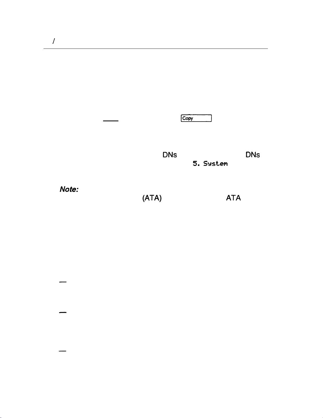
Set Copy
This feature is to copy of system programming
(Configuration and Administration) from on8
another.
also copied, but system-level programming will copied
along with it. Copy appears on display as Set
and is by using Configuration code.
programming on individual can
System Version
System Version you to not8 version numbers of the
software in the System Processor
Feature Cartridge.
Version numbers can be used to determine whether you have
the latest software release, and to trace a software fault if on8
occurs.
For
instance:
(SP)
software, residing in the
to
COPY
SP
version numbers can indicate a Software Cartridge
incompatibility.
SP
and telephone version numbers can indicate a
version incompatibility.
SP
and functional terminal version numbers can indicate a
functional terminal incompatibility.
To
check the version number, start with the display showing
System
1. Press
The display shows the version number of the
2.
Writ8 the
Maintenance record.
Version:
SP
version number on the appropriate
SP.
Compact
Installer Guide
Page 20

Programming 13
Chart 3
Programming Overview
5.
6. Service Modes
The M7208, and M7324 Telephones can
be used with the Compact
system. Programming is done
with an M7208, M7310, or M7324 Telephone. as shown on the
following page.
Page 21

14
Programming
Telephone
You should have two aids
Telephone
to
assist you in completing your
M7324 Telephone
programming:
Programming Record
The Compact Programming Record may already have
been completed before installation. It describes the settings to be
programmed into
a
Record serves as a record of the settings programmed at initial
installation and during subsequent upgrades.
system. Also, the Programming
Default
settings: Many of the programming settings are
determined during System Startup according to the selected
template. Any of these settings may later be changed during
programming. In the Programming Record, these default settings
are
shown in bold characters for the Square template.
Programming Overlay
The Programming Overlay is placed over the buttons of the
telephones, and provides an aid in recognizing the
function of the buttons during programming. The Programming
Overlay can be found at the end of this guide.
Compact
Installer Guide
Page 22

Programming 15
The Programming Overlay for the M7208 Telephone is placed
over all of the eight memory buttons (Figure 11). The
Programming Overlay for the M7310 and M7324 Telephones
(Figure 11) is placed over the top four memory buttons with
indicators.
Figure 11
the M7310 and M7324 Telephone (bottom)
Programming Overlay for the M7208 Telephone (top) and for
Page 23

16 Frogramming
System Startup overview
Perform
installed and powered up. System Startup is used by the installer
to choose the appropriate template before starting programming.
There are three templates available: Square, Hybrid and PBX.
The Compact
template does.
All Configuration and Administration data will be retained for at
least
System Startup after the system hardware has been
Programming Record explains what each
CAUTION
Startup is to be used for initial installation only, or after a
system software upgrade with a new Software
Cartridge. Do not use Startup after
operation; the procedure erases all system
administrative data.
three days if the power fails or if the
is in
system is
powered OFF. After three days without power, it may be
necessary to perform System Startup again.
Do
not
attempt Directory Number (DN)
changes within
two minutes of System Startup (using the Change
option of
Data).
Attempting a DN change
may disable the ports.
System Startup Access
The System Startup Access code and
by Installers
The
correct Startup code must be entered no later than 15
minutes after the
Startup code entered at any time after the 15 minute interval
results in the message
re-power the system again to
process.
to access
System
Startup.
system has been powered up. A
Startup denied.
prepare for the System Startup
a password are used only
If this occurs,
Page 24

Entering System Startup
If at any time you do not wish to continue with entering
System Startup, press
Select a telephone from which to program. Place the
1,
correct Programming Overlay over the buttons of the
telephone. A button may be used during programming when
its indicator turns
2.
Using the telephone dial pad, press the System Startup
Access code:
Which is the same as:
Programming 17
3.
At the
Password:
prompt, enter the Installer password:
Which is the same as:
(The Installer password is not shown on the display.)
The default password is
which you will have to use
if this is the first time that Configuration programming has
been accessed. If Startup must be performed on an existing
system which has already been programmed, the Installer
password might have been changed. The change should
have been properly recorded in the Compact
Programming Record.
If the password is entered correctly, the display shows
Reset
Proceed to change the system template as
described in the next procedure.
OR
If the Password has been entered
remains on the display. Press the
RETRY
display button (or
Password:
password.
on the M7208 Telephone) and the correct
Page 25

18 Programming
Choosing the system template
1.
The display shows
Startup and choose the system template, press
on the M7208 Telephone).
OR
To exit from System Startup, press (or
M7310 and M7324 Telephone).
Reset memory?
To continue with System
(or
on the
The display
shows
ate:
Square.
To accept the
Square template, go to step 3.
OR
To select another template, press
the M7208 Telephone} to select another
3.
To accept the template shown and exit from System Startup,
press
NEXT
or (or on the M7208 Telephone).
(or
template.
System Startup is complete when the time and date appear
on the telephone display.
Chart 4
System Startup
START HERE
digits for Code
on
Reset
ate
Jan am
Installer Guide
Page 26

Configuration Overview
Configuration programming allows you to specify basic system
characteristics for the customer site. Configuratian is not
accessible to System
Configuration provides access to the following programming
sections:
Data
2. Line Access
Programming 19
3,
4. Miscellaneous
5. System Data
Handling
Configuration Access Code
1.
Press
OR
Press
Installer Password
1.
At the
password. The default password is which you will
have to use if this is the first time that Configuration
programming has been accessed.
2.
If the password is entered correctly, the display shows
OR
If the Password has been entered incorrectly,
remains on the display. Press the
Password:
prompt, enter in the existing Installer
Password:
display button (or
password.
Note:
on the M7208 Telephone) and re-enter the correct
For the security of Configuration data, do not give the
Startup access code to anyone.
Page 27

20 Programming
Chart 5 Configuration Overview
START HERE
Enter digits for Configuration code
--
Heading
3.
Call
Hand1
Back
Next
Page 28

Programming 21
Data
Use
1. Data
external line.
When you are finished programming the Data settings
for a line, you may copy those exact settings to another line by
using the display button (or on the M7208
to program characteristics for each
Telephone) at the
Show 1
prompt.
Entering the line to be programmed
Enter any available line number between 01 and 06.
Dial Mode
A dial mode can be assigned to each line. The mode defines the
signaling that the line will use. The default mode is Pulse.
Another possible mode is Tone.
Lines that use Dual Tone Multi Frequency (DTMF) tones,
should be set to Tone.
Full
An external line is affected by Full Automatic Hold when it is
placed on hold when no digits have been dialed on
line is selected. The default setting is No, which means that the
external line is not held. Another possible setting is Yes.
it, but
another
This feature is useful if a “hotline” or “ring down tie line” is
required.
Compact Installer Guide
Page 29

22 Programming
Line Type
A type can be assigned to each line. The type defines how the
line is to be used in relation to other lines in the system. The
default type is Public. Other possible types are Private, Pool A,
Pool B and Pool C.
If you define a line as Public, the line can be accessed by
more than one telephone.
If you define a line as Private, the line can only be assigned
to one telephone.
If you assign a line to a Line Pool, that line can be available
to any telephone that is assigned access to that Line Pool.
If a line is assigned to one of the three Line Pools, but the
line is not assigned to any telephone, that line can only be
used for making outgoing calls.
If a line is assigned to one of the three Line Pools, you must
remember that there are still two more programming settings
that must be assigned before a Line Pool can be used:
l
You must assign Line Pool Access to telephones in Line
Access.
l
You must assign Line Pool Access codes in
Miscellaneous programming.
Prime telephone
The Prime telephone provides backup answering for the selected
line. The default Prime telephone has the internal number 21.
Other possible settings are any allowable internal numbers, or
None.
Each line can only have one Prime telephone.
Any Prime telephone can be assigned to provide backup
answering for more than one external line. All of these lines
do not necessarily have to appear on a line button with an .
indicator; however, monitoring lines is made easier if there is
a line button for every external line.
Page 30

Auxiliary ringer
An auxiliary ringer can be enabled or disabled for calls coming in
on the line. The default setting is Yes, which means that the
ringer will ring. Another possible setting is No.
Auto privacy
Auto privacy can be enabled so that other users who have
access to a line on their telephone, cannot use that line while a
call is already in progress on the line.’ If disabled, Auto privacy
allows a user to select a line in use at another telephone, and
join an call.
Programming 23
Chart 6
Data
1.
or
line:
4
Back
Dial Pulse
I
Back
Full N
Line ic
Data
2. Line
I
I
set:
Next
.
.:
Back
21
I
Compact Installer Guide
Page 31
24
Programming
Line Access
Use Line Access to program characteristics for each telephone.
These characteristics establish which lines the telephone may
use.
When you are finished programming the Line Access settings for
a telephone, you may copy those settings to another telephone
by using the
COPY
display button (or on the M7208
Telephone) at the
Show
set:
prompt.
Entering the telephone to be programmed
Enter any available DN. Default range from 21 to 36.
can be later changed to a new number in
Configuration programming.
Settings are automatically applied for the Analog
Terminal Adapter
Installation Guide for the defaults.
if installed. See the
Data
Line assignment
You can assign one or more lines to the telephone. You can
remove lines assigned to the telephone. The default line
assignments for the Square template are Line 1 and Line 2 to
each telephone. Any other lines can be assigned to each
telephone.
of
A Private line can only be assigned to one telephone. (It is
also automatically assigned to the Prime Telephone for that
line.)
If you assigned the PBX template in System Startup, a Line
Pool is assigned to the telephone instead of external lines.
You can add lines if you wish. This would allow the
telephone to ring for incoming external calls.
If a line is assigned to a Line Pool, but is not assigned to any
telephone, that line can only be used to make outgoing calls.
Page 32

Programming 25
Answer
Up to four buttons on a telephone can be programmed for
answering calls to the of other telephones. The default is
No Answer
For ‘each line assigned’ to a telephone; you can determine
whether incoming, calls will ring at the telephone. Possible
settings are Ring and No Ring. The default setting is Ring.
.
Line pool access
You can determine which Line Pool each telephone has access
to. Possible settings are Yes and No. The default setting is No
for each of the three line pools, which means no telephone has
default access to Line pools.
Assigning a Line Pooi to a telephone saves on the number of
buttons required for external lines on the telephone.
Intercom buttons
You can determine the number of Intercom buttons on the
telephone. Possible settings are
is 2.
A minimum of two Intercom buttons are required for
conferencing with two other
system.
A minimum of one Intercom button is required if internal calls
are to be made or received from the telephone or Line Pools
are to be accessed from the telephone.
or 2. The default setting
telephones in the same
Compact
Installer Guide
Page 33

26 Programming
Prime line
You can assign the Prime line for each telephone. The Prime line
is the first line to be automatically provided at a telephone when
you make a call. The appropriate Prime line will depend on the
customer’s requirements. The default setting is None, which
means that no Prime line is assigned to the telephone. Other
possible settings are an external line (Line number), Line Pool A,
Line Pool
A Prime line is not related to the operation of a Prime
telephone.
Line Pool C or intercom
(I/C).
Chart 7
Line Access
Back or
Heading
Show
(Line
Rinsing
/Line Pool access
4
Back
B&k
Back
4
Back
set:,
digit8
Next
Call
COPY
Show
Show
Show
Show
Back
Intercom 2
Page 34

Call Handling
Use Call Handling parameters to program system-wide
characteristics for certain call features. These characteristics are
not associated in programming with any particular line or
telephone.
Held reminder
Choose if the Held Line Reminder feature is to be active for
external lines. Possible settings are Yes and No. The default
setting is No. If Yes, the programming menu takes you to the
Remind delay setting.
Remind delay
Assign the delay (in seconds) before the Held Line Reminder
feature begins at the telephone which has put an external line on
hold. Possible delays are 30, 60, 90, 120,
The default delay is 60 seconds.
Programming 27
and 180 seconds.
This setting does not appear if Held Line Reminder is not
active.
DRT to prime
Choose if the Delayed Ring Transfer to Prime telephone feature
is to be active for all external lines associated with the Prime
telephone. yes, the
delay setting. Possible settings are Yes and No. The default
setting is Yes.
Ensure that you have an operational Prime telephone.
This setting applies only to external lines with an assigned
Prime telephone.
programming menu
takes you to the DRT
DRT delay
Assign the delay (number of rings) before an unanswered
external call is redirected to the Prime telephone. Possible
delays are 1, 2, 3, 4, 6 or 10 rings. The defautt delay is 3 rings.
To estimate the delay time in seconds, multiply the number
of rings by six.
Compact
Page 35

28 Programming
Transfer callback
Choose the delay (number of rings) before a transferred external
call will callback to the originating telephone. The possible delay
is 3, 4, 5, 6, or 12 rings. The default delay is 3 rings.
To estimate the delay time in seconds, multiply the number
of rings by six.
Park prefix
Park prefix assigns a one digit code number to retrieve a parked
call. The default Park prefix is 1. Any digit from 0 to 9, or none,
can be assigned, providing it is not the first digit of a DN or Line
Pool access code.
Park timeout
Assign the number of seconds before a parked external call will
callback to the originating telephone. The possible timeout is 30,
45, 60,
timeout is 45 seconds.
90, 120, 150, 180,
300, or
600
seconds. The default
Camp timeout
Assign the length of delay before a camped call is returned to the
telephone which camped the call. The possible timeout is 30,
45, 60, 90, 120, 150, or 180 seconds. The default timeout is
45 seconds.
Directed pickup
Directed pickup allows any telephone within the system to
answer calls by specifying the ringing telephone’s number (unlike
Call Pickup Group which only allows pickup of calls within a
specified group of telephones). The default is Yes.
On hold
Choose what a caller will on an external line when the line
has been put on hold. Possible settings are Tones, Music, or
Silence. The default setting is Tones.
A customer supplied music source must be connected in
order to hear music.
Page 36

Programming 29
Chart
Call Handling
I
:
Headiig
Held reminder:
Back
Remind delay:
I
Back
DRT
show
Next
,
N
3
I
__
l
i
N”
1 l
neouo
Prefix:
Park
timeout: 45
timeout: 45
Directed
hold:
,
1 I
Next
,
Tones
Compact Installer Guide
Page 37

30 Programming
Miscellaneous
Use Miscellaneous settings to program various system-wide
characteristics. These characteristics are not associated in
programming with any particular line or telephone.
Background Music
Choose if the Background music feature is to be available within
the
default setting is No.
If this feature is enabled, ensure that an external music
source has been connected to the KSU. (This music source
is also used for the Music on Hold feature.)
Direct-dial digit
Choose the digit you dial in order to get the Direct-dial Telephone
to ring. The possible settings are any valid digit from 0 to 9, or
None. The default setting is the digit zero.
system. Possible settings are Yes and No. The
Link time
Assign the Link time (in milliseconds). Possible times are 100,
200, 300, 400, 500,
default Link time is 600 milliseconds.
The Link time required will depend on the requirements of
the host PBX,
be accessed by
Link is another name for Recall or Flash.
600,700,
or other switching system that must
800, 900, 1000
milliseconds. The
Telephone relocation
Choose if the Set Relocation feature is to be active. Possible
settings are Yes and No. The default setting is No.
It is advisable to turn Set Relocation ON after the telephone
installation and programming has been done. This provides
you with more flexibility in testing equipment. If this feature is
disabled, and a telephone is moved, that telephone’s internal
number and Administration data remain with the physical
port.
Page 38

Programming
If new telephones are being installed at the same time that
other telephones are being relocated; you should perform
the following procedure to ensure that Set Relocation occurs:
Select Yes to ON Set Relocation.
2.
Unplug the telephone that is to be relocated.
3.
Plug the telephone into its new location.
4.
Plug a new telephone into the old of the
telephone that was moved.
Host delay
Host delay programs the delay in milliseconds between the
selection of an outgoing line and the moment that sends
dialed digits or codes on that line, The default is
1000 milliseconds.
External code
Assign a one-digit External line access code, or none. The
default is 9. The External code allows an M7100 Telephone or
an
to access external lines.
Line pool codes
Assign Line Pool Access codes for each of the three possible
Line Pools. The possible settings are a one to four digit number
(starting with 8, or 9) or None. The default setting is None.
The codes cannot start with the same first digit of an internal
number already assigned to a telephone.
Codes starting with the same number must be the same
length.
Ensure that the System Coordinator knows the codes.
Compact Installer Guide
Page 39

32 Programming
Installer password
This allows you to change the Installer password for access to
Configuration programming. The possible setting is any
combination of one to six letters or numbers. The default Installer
Password is which is the same as
The default password is required to first gain access to
Configuration programming. However, it is advisable to
change that password to a new one.
Chart 9
Miscellaneous
4.
Back
Direct-dial
Sack
Link time:
Set rel
aneous Srsten Data
Next
N
1
Back
Host
Sack
External
Sack
Next
code: 9
Show
Page 40

System Data
Use this to change the internal number or Directory Number (DN)
of an individual telephone.
Do not attempt internal number changes within two
minutes of System
Programming
,
33
Enter the appropriate internal number when you are prompted for
the old and the new internal number, A message will appear on
the display if either internal number is invalid. The possible
settings are any valid internal number
is no default setting.
No internal number changes occur until the Configuration
session ends. (Press the button.)
If the “new internal number” already existed for another
telephone, that telephone will be given the “old internal
number”.
There can be only one telephone for each internal number.
An internal number and a Line Pool Access Code cannot
start with the same digit.
Chart 10 - System Data
20 and 99. There
Note:
If you change a DN, you cannot continue programming
in any of the other sections while in the same
Configuration session. Press the button to end the
session.
Compact Installer Guide
Page 41
34 Programming
Set Copy
Use this for copying System data (programming) or System and
User Administration data (Personal programming) from one
telephone to another. System data is programmed in
Configuration and Administration. User Administration
programming is performed by the user at the individual
telephone, and allows the telephone to be customized according
to the user’s requirements.
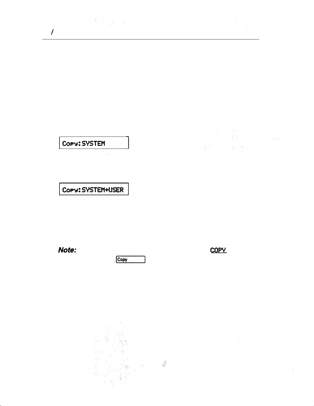
Set Copy Options
data
When this message appears on the display, you can choose to
copy System data.
When this message appears on the display, you can choose to
copy System and User data. Both telephones must be the same
model and connected to the system before this option can be
used.
Do not confuse
button (or
C. Set
COPY
with the
display
on the M7208 Telephone), which is
for selective copying of specific groups of settings from
one telephone or external line to another.
Page 42

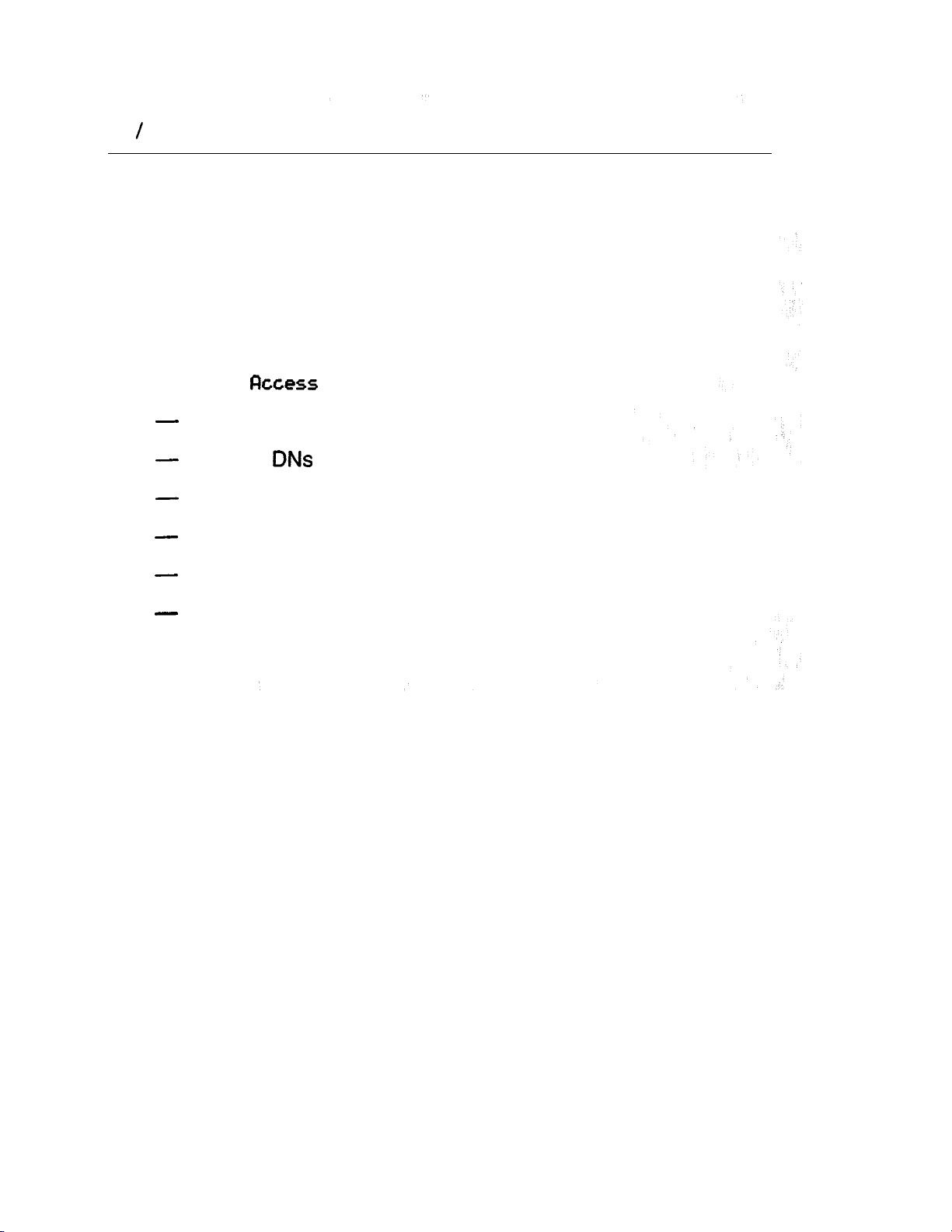
Set Copy characteristics which can NOT be copied
options
Log
Directory
Private line appearances
Prime telephone designation for a line
Direct-dial telephone designation
Extra-dial telephone designation
Control telephone designation for a line
Service mode Ringing telephone designation for a line
Receive tones
Logging set designation
Show external Voice Message
Log space
First display
Compact Installer Guide
Page 43
36 Programming
Characteristics which CAN be copied
Except for those characteristics previously listed, all telephone
related settings can be copied to a destination telephone,
overriding any previous programming. Listed below are the
System level settings and User Administration settings which can
be
copied.
System settings in Configuration programming
2.
Line
Line assignment
Answer
Ringing line preference
Line pool access
Number of Intercom buttons
Prime line designation
Page 44

Programming 37
System settings in Administration programming
5.
Set Filter
Full handsf ree
Wandsfree answerback
pickup group
Paging
Auxiliary ringer
Direct-Dial
Forward on busy
Forward on no answer
Receive tones
Priority call
9. Services
Vmsg
settings
if desired, the following Personalized settings can be copied
along with the System data:
Programmable button assignments (Internal Autodial,
External Autodial, and feature access)
Language choice
Personal Speed Dial entries
Compact Installer Guide
Page 45

38 Programming
Using Set Copy
You can only enter Set Copy through the Configuration access
code and with the Installer password.
Entering Set Copy
After
1.
Press twice.
The display shows
2.
Press
Chart 11
Set Copy
C. Set cow
C
OPY
Back
to go to
:
data
Enter pad digits
appears on the display:
C. Set
COPY
.
C
OPY
:
D.
data.
Uersion
.
Page 46

Testing the and
of the and verifying the tone. If you do
get a tone; plug a single-line into the
dial tone, check all your wiring or contact your telephone
company.
2.
Check all internal connections
telephone from another
3.
crackling, static, hums, or any other unusual noise,
4.
If there are any problems, refer to other procedures in this
section.
5.
Verify the visual indicators:
external lines by selecting each line in turn at one
line at the distribution panel. If you still do not get a
by calling each
telephone.
the quality and clarity of all connections. Check for
To check a button:
1.
Select a line or Intercom button.
that button should appear.
The
indicator beside
To check the display:
1.
Press
The display shows Press
2.
Press the button to exit from
a button.
this
feature.
Compact installer Guide
Page 47

40 Troubleshooting,
Terminal Adapter trouble
Check the single line telephone connection by using an
installer’s test telephone.
2. Check the connections to the jack.
3. Check the connections to the
4.
Disconnect the and replace it with a working Not-star
telephone. If the telephone still works properly, this verifies
that the KSU is working properly.
5.
Verify that programming has been done as described in the
Analog Terminal Adapter Installation Card.
6.
If the trouble seems to be in the KSU, double check all wiring
and programming options. If this does not help, refer to the
KSU down
This unit must be powered from a Class source
that is UL and CSA Listed.
section of Troubleshooting.
WARNING
Auxiliary Ringer trouble
1.
If the Auxiliary Ringer is used for Service Modes, ensure that
Service Modes is activated from the Control Telephone.
2.
Check the wiring between the Auxiliary Ringer generator and
the ringing device. (See the Internal Wiring chart.)
3.
Check the wiring between the Auxiliary Ringer and the
distribution panel.
4.
Check the Auxiliary Ringer contact operation with an
ohmmeter across the pins.
5.
Check that the Auxiliary Ringer is programmed to ring for
any of the following programmable settings:
Page 48
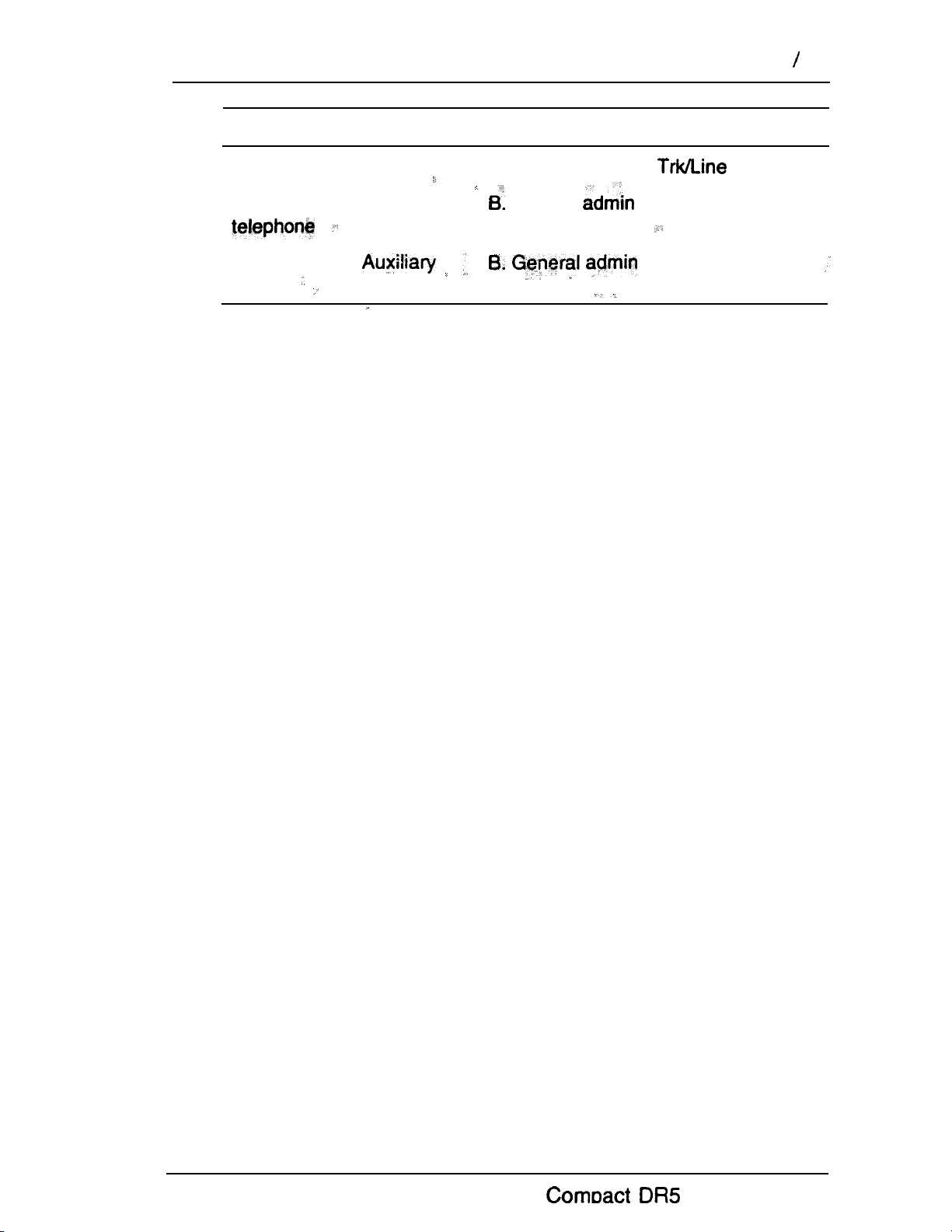
Troubleshooting 41
Feature
Ring for a specific line
Ring ‘for a specific
___
Service Modes
Ringer
Programmed in:
A. Configuration (1. Data)
General (5. Capabilities)
(6, Service Modes)
,
Installer Guide
Page 49

42 Troubleshooting
Cal Identification Interface
1.
Use the Call Information feature on an incoming call to verify
of
the operation
2
Check the connections to the Cll. Refer to the
,
3.
4.
5. Replace the
Installer Card for installation details.
Verify that the programming has been done as described in
the Compact
System Coordinator Guide.
Verify that you are subscribing to visual Call Display services
from your local telephone company.
the
Programming Record and the Compact
Dial tone absent (on external lines)
1.
Use Button Inquiry to check the feature of
a programmable memory button that you think is assigned
as an external line.
2.
Check for a dial tone by using an installer’s test telephone at
the connections for the external line on the distribution block.
3.
Check the connections between the KSU and the distribution
block.
External Paging trouble
1.
Check the wiring between the connector and the
paging amplifier.
2.
Check the wiring between the connections shown in the
Internal Wiring chart.
3.
Test the external Page feature to ensure
that it is working. The output from the
775 across 600
KSU is
Page 50

KSU down
1.
Check that the AC power cord is properly connected.
that the Software Cartridge seated in its slot.
Troubieshooting 43
is
3.
If AC power and the LED indicator on the KSU is
OFF, replace the KSU.
Page 51

44 Troubleshooting
Music on Hold/Background Music trouble
1.
Ensure that the volume control is turned
up and you are using the Background Music feature code
Check the applicable Configuration programming settings to
ensure that the feature is enabled:
Feature
Music on Hold
Background Music
3.
Check the wiring between the music source and the
connector.
4.
Check the polarity of the connections between the music
source and the distribution block.
5.
Ensure that the music source is turned ON, is operational,
and has the volume control properly adjusted.
Telephone dead
1.
Check for dial tone.
2.
Check the receiver cord connection.
Programmed in:
3. handling
4. Miscellaneous
3.
Check the display. If the display is unreadable, ensure that
the display contrast adjustment
appropriate.
4.
Check the internal wiring at both the modular jack and the
distribution block.
5.
Check the internal line.
6.
If the problem persists, replace the telephone with a known
working
Note:
An internal line should have between 15 and 20 Vdc
across the Tip and Ring when the telephone is
disconnected.
telephone.
q
is
Page 52

If you are required to continue programming, refer to the
Compact System Coordinator Guide.
Give the System Coordinator the Compact Programming
Applying the button labels
If you perform all of the programming for a system, apply the
appropriate button labels on the telephones. Before you apply
button labels, activate the Button Inquiry feature
to avoid activating features as you put the
button labels onto the buttons.,
For the customer
Remember to leave the following items at the installation site:
For the System Coordinator
Compact System Coordinator Guide (with the
Programming Overlays)
Compact
Optional equipment User Cards (for example, the BLF and
Spare button labels and button caps
Telephone User Cards (for the M7208, M7310,
and M7324 as required)
compact
Compact Prime Telephone card
Programming Record
In the KSU pocket
Compact Guide
Optional equipment Installation
BLF and
cards (for example, the
Compact Installer Guide
Page 53

46 Finishing up
Personal programming,
Information on telephone feature programming and operation
can be found in the
Compact System Coordinator Guide.
Display services
Your system can access information contained in Call
Display services offered by your public telephone company, and
uses that information to provide additional messaging tools to the
user.
You can access Call Display information only if you
subscribe to the services, and if you have Call
Identification Interface hardware installed. Contact your
Service Representative for more information.
Call Display information may be shown on your telephone
display when a call is alerting, identifying the caller to you.
Specific telephones are programmed to receive this information
in Administration programming. For more information see the
Programming chapter in the
Guide.
Compact Coordinator
Page 54

Coordinator Guide
Page 55
Welcome to
System Coordinator’s role
Assisting your co-workers
Your Service Representative
Enhanced Transfer
Call Display services
1
2
2
2
3
Programming
How to do programming
Planning
Programming tools
Administration overview
Administration headings
Entering Administration
Exiting Administration
Moving through Administration
Using the Overlay
The
Programming details
System Speed Dial
Names
Time and date
Direct-Dial
Capabilities
Dialing Filters
Telephone (Set) abilities
Line abilities
Class of Service (COS) passwords
Service Modes
Password
Defaults
Services
Auto Call Info
Telephone (Set) Services
Voice Message Center telephone numbers
Voice Message Center lines
Copying settings
display buttons
13
13
13
15
16
16
18
18
19
20
22
23
25
29
32
35
36
36
40
45
45
48
52
53
54
54
55
56
56
57
Compact System Coordinator Guide
Page 56

ii
Contents
Telephone programming
Capabilities programming
Programming reminders
telephones
Prime telephone
Page zones .
tine Pools
Miscellaneous programming
Call Pickup Groups
Service
Modes
Telephone features
Using features
Answering the telephone
Related features
What line indicators mean
Rings you may hear
Displays
Prime telephone displays
Notes
Displays
Notes
Call Forward
Related features
Displays
Notes
Call information
Related features
Displays
Notes
Call Log
Related features
Displays
Notes
Call Park
Displays
Notes
Call Pickup
Displays
57
57
57
58
59
60
60
60
60
61
62
63
64
67
68
69
69
69
72
73
74
74
76
77
78
78
79
80
81
81
81
82
88
88
91
92
92
93
94
94
Compact System Coordinator Guide
Page 57

Contents
iii
Notes
Call Queuing
Notes
Camp On
Related
Displays
Notes
Conference
Displays
Notes
COS Password
Displays
Notes
Customizing your telephone
Related
Dialing
Related features
Displays
Notes
Do Not Disturb
Displays
Notes
Feature Programming
Displays
Notes
Group Listen
Displays
Notes
Handsf
Notes
Hold
Notes
Host System Signaling
Host system signaling codes
Displays
Notes
tine Pools
Displays
Notes
Messages
Related features
features
features
95
97
97
98
98
98
99
100
102
103
104
104
104
105
111
112
113
114
116
117
117
117
118
119
120
121
121
121
122
123
124
125
126
126
128
128
129
129
130
131
133
Compact System Coordinator Guide
Page 58
iv Contents
Displays
Notes
Telephones
Buttons
Headset
Hearing Aid Compatibility
Wall Mounting
Page
Related features
Displays
Notes
Priority
Displays
Notes
Service Modes
Displays
Notes
Special Telephones ,
Speed Dial
Notes
System features
Speed Dial
features
Displays
Transfer
Displays
Notes
Voice Call
Displays
Notes
133
136
137
137
140
140
141
141
142
142
143
143
144
145
145
146
147
150
151
152
153
156
157
157
158
159
161
162
163
163
User cards
Glossary
Index
Compact DR5 System Coordinator Guide
165
191
207
Page 59
In addition to basic telephone service, your digital key
system has many extra features that
office communications,
take will help you to learn
the various tasks which a System Coordinator should perform.
This guide also serves as a reference when you assist
co-workers to become familiar with
When a telephone system is first installed, it takes a bit of time to
settle into using new equipment.
orientation by providing straightforward features and simple
instructions.
greatly improve your
features.
minimizes this
System Coordinator’s role’
The System Coordinator plays an important role in customizing
to suit the organization and updating information as the
office grows and changes.
can be customized at three levels:
Personal programming
Personal programming is done by individual telephone users
who wish to personalize their telephones by
programming features and telephone numbers onto specific
memory buttons.
Administration programming
Administration programming is done by the System Coordinator,
when you want to change various system-wide settings, as well
as some specific settings for each line or telephone.
Configuration programming
Configuration programming is usually done for you by the
Installer or Service Representative when
installed. Specific system-wide parameters are set up in
Configuration.
is being
Compact DR5 System Coordinator Guide
Page 60

2 Welcome to
Assisting your co-workers
It is human nature to ask someone how to do something rather
than read a user guide. The System Coordinator may be asked
to demonstrateto co-workers how to select and use
features. To help you prepare for that possibility:
Familiarize with the procedures for using.
features. Examine the components of your system,
identifying the buttons on the different types of
telephones Read the Telephone User Cards chapter of this
Guide for more information on each telephone.
Familiarize yourself with the various programming reminders
provided at the end of the Programming chapter of this
Guide. Distribute copies of these reminders to your
co-workers after filling in information such as System Speed
Dial numbers and names.
It is important for everyone in the office to know that you are the
System Coordinator and to know when you are available for
consultation. You may wish to schedule sessions for small
groups or provide individual assistance to co-workers for
programming features on their
Your Service Representative
Ask your Service Representative for the service department’s
telephone number, and write it down. If you have problems with
your
If you have problems with programming or using any of the
features, first read the appropriate section of this Guide and try
again before calling your Service Representative.
equipment, telephone your Service Representative.
Enhanced Transfer ,
There is a new procedure for using the Transfer feature in this
system. If you are upgrading a Compact system, be
sure to familiarize yourself with the new procedure.
telephones.
Compact
System Coordinator Guide
Page 61

Call Display services 3
Call Display services ,
Most public telephone companies offer Call Display services
which provide information about an incoming call. The caller’s
name, telephone number and in some cases, long distance
indication, can be shown’on a telephone with a display. Your
system uses this information so that you can:
view incoming call information’as welt as the line
name that receives the call,
keep a log of incoming call Information and,
view an integrated display that appears when you have
received a message from either an internal
Mail message from an external caller.
.
user or a
You can access Call Display information only if you
subscribe to the services offered by your public
telephone company, and if you have the appropriate
hardware installed. Contact your Service Representative
for more information.
Call Display Information
Call Display information may be shown on your telephone
display when you answer an incoming call. In addition to the
caller’s name, telephone number and long distance indicator, if
available, your
received the call.
In the case where several users share a line, only one telephone
can be designated to automatically receive Call Display
information when a call is alerting on that line. If the is
transferred or camped to another telephone, the Call Display
information is automatically available to that telephone.
system can display the line name that
If a line is not administered to automatically deliver Call Display
information to a telephone, the user can invoke the Call
Information feature (see Telephone Features section) or answer
the call to view the information.
Compact
System Coordinator Guide
Page 62

4 Call Display services
Depending on your requirements, Call Display information
presents several convenient options.
When is identified before the call is answered, you
can answer using a personal greeting. You can also prepare
yourself prior to answering the call by retrieving any relevant
documents,, or
discussion, ,
The Long Distance indicator alerts you that an incoming call
is long distance and may therefore have higher priority.
If you are unable to immediately attend to an incoming call,
you can use the calling information to make a quick note.
You can shorten the interruption time of a call from a
recognized person. For instance, you can quickly answer
the call and let the party know that you are busy but will
return the call soon.
orienting yourself to the expected
A telephone can be programmed to first view either the
caller’s name or number or line name, For example, an
attendant might wish to see the calling number and area
code first in order to transfer the call according to sales
region. The salesperson’s telephone could display the
caller’s name first so they can answer with a personal
greeting.
Compact DR5 System Coordinator Guide
Page 63

Call Display services 5
Display information allows you to answer calls on a
priority ‘basis, For example:
l
If several calls are alerting at your telephone at the same
time, you can request information about the calls to
decide which one may be more important.
l
If you are already on a call, information a second
call starting to alert at your telephone can help you to
decide whether to answer the second call or remain
connected to the first call.
If you are in a meeting, the information associated with
an incoming call can help you determine if the call is
important enough to interrupt the meeting.
l
If you have several calls on hold and wish to identify the
callers, you can view the Call Display information
associated with each of the calls to help you determine
which one you will respond to first.
Programming tips
In order for the designated telephone to automatically receive
Call Display information, it must be programmed to ring for
incoming calls on that line.
Before programming Call Display information you may wish to
consider the following:
which individual would benefit the most from automatically
receiving Call Display information on an alerting line?
how are calls routed and what information is the most
important to know before a call is answered? For instance, if
certain lines are private to individuals, an attendant might
wish to first view the line name to determine who the
incoming call is for.
Compact System Coordinator Guide
Page 64
6 Call Display services
Call Log
The Call Log feature uses incoming Call Display
information to make a record of
Log also records several other useful facts such as the time and
date of the log entry, the number of repeated calls by the same
caller and which telephone answered the call if it was
subsequently rerouted and handled by someone else in the
system.
When the volume of incoming calls exceeds the ability of
employees to handle all calls, or when staff are unavailable to
answer calls, Call Log provides a convenient means of capturing
information about missed calls.
When connected to a call that has Call Display information, the
feature of
accurate means of recording the caller’s information for future
use (see Telephone Features for more information).
Call Log can be used to provide a quick and
,
details for follow-up. Call
Programming tips
Call Log space can be assigned to individual telephones
according to how much space you wish to allocate to each user.
In order to maximize the value of Call Logs and avoid confusion
for the end user and their customers, it is important to consider
the following when configuring Call Log:
Application of Call Log
Does the user want to return customer calls, track the
numbers of calls unanswered, keep a record of most
commonly called numbers, etc.?
Who is most interested in logging calls on a particular line?
For instance, dentists working in a clinic may have an
individual line assigned to them but prefer that the
receptionist handle all of the calls logged on their line.
Compact
System Coordinator Guide
Page 65

Call Display services 7
strongly recommend that you, limit the number of users
logging calls for the same line,
as this would be confusing. For
example, if two users are logging calls for the same line, they do
not know who the call was originally intended for nor are both
Logs updated when one of the users returns a customer‘s
call. Potentially a customer could be called back twice,
There are
at more than one set.
Recommended configuration 1
situations where the same call needs to be togged
__
,
All lines appear at the Attendant Position, Incoming calls are first
answered on the Attendant’s set and then transferred to the
required destination.
The Attendant wants to track all calls unanswered on the system,
during working hours and after hours. The users want to capture
in their Call Log, any calls which they did not answer at their set
and be able to return those calls from the log.
The Attendant Position logs No
the users log calls
Unanswered
answered
on all lines and
In this configuration the
user will log calls transferred to them via intercom from the
attendant or another user, even though the administration setting
is
Set:
N). Thus the entries in their Call Log are
specifically meant for them.
Compact System Coordinator Guide
Page 66

8 Call Display services
Logs with
Attendant’s telephone
an
Attendant Position
Programming:
Attendant Position
Configuration: Administration:’
Line Access Log Defaults
Line Assignment
(all lines to appear at
the Attendant’s set)
to all sets for example, 25.)
Set Services
Ringing
Set Programming:
one answered)
Set Users
Administration:
Set Services
Set: N
(no lines assigned)
Set Programming:
(assign log
Set:
Compact DR5 System Coordinator Guide
Page 67

Call Display services
Recommended 2
user has a unique line appearing at their set. The
users have a variety of requirements in terms of logging calls.
Using
capabilities specifically for their
Call
Logs
with dedicated lines
q
the users can program logging
Programming:
Configuration:
Line Access
Line Assignment
Ringing
Administration:
Log Defaults
Set Services
Set:
Set Programming:
(No one all Calls,
No
Compact System Coordinator Guide
Page 68

10 Call Display services
Recommended configuration 3
The Not-star system has lines 1 and 2 appearing on all sets. The
supervisor wants to log all calls for lines 1 and 2 at his/her set in
order to analyze call traffic. Two users have been selected to
return unanswered customer calls; To avoid confusion when
logging and sharing lines, one user logs Ho
calls on line 1 and a second user logs No one answered calls
on line 2. This dearly identifies who is responsible for returning
calls for each line and ensures that only one person calls the
customer back,
Call
Logs with shared lines
answered
Programming:
Configuration:
Line Access
Administration:
Log Defaults
Line assignment
Ringing
Set Services
Show Set: 21
Lines Y
Show Set: 22
Show Set: 23
Logging Set:
Compact DR5 System Coordinator Guide
(supervisor’s set)
Set:
Set: Line Y
Line
Y
Page 69

Call Display services 11
For more information, see the
Call tog Feature
Message Waiting you to send and receive internal
messages
have subscribed to Voice Mail Messaging (provided by your
public telephone company), and visual message waiting
indication is available, Message Waiting also informs you if you
have messages at your Voice Message Center and allows you
to:
receive a visual indication that you have messages waiting,
as maintain a record of your messages. If you
your Voice Message Center to hear your messages and,
clear the message waiting indication from your display.
Programming tips
In order for a telephone to. use this feature, it must have a line
appearance and Message Waiting must be activated for that line
by your public telephone company.
It is possible for two or more telephones to share a line
appearance. You must determine if one, some or all of the users
sharing a line will receive Message Waiting notification. If it is a
sub-group,
appropriate to share the feature providing that the users have an
agreed upon procedure for retrieving and deleting messages.
For further information on Call Information, Call Log and
Messages, see the Telephone features section. Programming
actions are described in further detail in the Programming
section.
as a sales team within a company, it may be
Compact System
Coordinator Guide
Page 70

12 Display services
Compact System Coordinator Guide
Page 71

The system comes programmed with default settings that may be
sufficient initially. programming is performed by
the System Coordinator, and lets you change settings that
probably have to be updated regularly staff turnover
or new business can also assign some features to
and This provides with real
flexibility in making your telephones work together.
This chapter contains detailed for programming
System Speed Dial codes, Names for lines and telephones, and
Time and Date information. If you are new to Administration
programming, you may want to get comfortable with these three
procedures before attempting other procedures.
Personal programming does not follow the same procedures as
Administration programming. Personal programming allows you
to assign a particular function to some of the keys, and is unique
to each telephone. For more information on Personal
programming, see the Feature programming description in the
Telephone features chapter.
How to do programming
The system is programmed using a M7208, or M7310
Telephone. Use the buttons on the telephone to program a
setting or to request a specific programming action.
guides you step by step on the telephone display while
you enter programming, select and change what you want, and
exit programming.
Planning
Only one Not-star telephone can access Administration
programming at a time. While programming a telephone, you
cannot use it to make or receive calls. While you are
programming, other users of the system may use their
telephones, but cannot program any memory keys.
Compact System Coordinator Guide
Page 72

Determine programming requirements
Read about the available programming settings in this chapter,
then determine how your co-workers would like the features
programmed.
Get the following information:
the numbers of the installed lines,
the internal telephone numbers of installed
telephones,
the telephone numbers to be programmed into System
Speed Dial,
the names for lines and telephones,
the lines and internal numbers that are subject to Line
abilities and Set abilities programming,
the required Filters,
the Set Abilities to be assigned to individual telephones,
how the system should be programmed to optimize the
Service Modes feature,
whether a new Administration password is required, and
whether Class of Service passwords are required.
Compact System Coordinator Guide
Page 73

Programming 15
Programming tools
A telephone
System programming can be performed on an M7208, M7310 or
M7324 Telephone.
The Programming Overlay
The is a cutout that labels
used during This makes it
easiei for you to ‘recognize the button that want.’
The Overlay for the M7208 Telephone is
placed over all of the eight buttons. The Programming Overlay for
the and M7324 Telephones is placed over the top four
memory buttons with indicators. The
Overlays are provided at the end of this book.
Programming
The Compact Programming Record
The Compact Programming Record provides a convenient
way to record what you have programmed. It also helps you to
plan your programming. Settings are grouped according to their
function.
Pages
programming many telephones or lines.
from the Record may be
photocopied as necessary
The Telephone User Cards
Each telephone has a Telephone User Card that
lists the most commonly used features.
The Compact Telephone Feature Card
The Compact Telephone Feature Card lists the features
that can be accessed with the
button.
for
Compact
System Coordinator Guide
Page 74

16 Administration overview
Administration
Administration programming lets you change settings for the
entire system, as well as settings for individual
telephones and external lines.
Pre-programmed default settings may initially be sufficient for
your needs. You can use Administration programming to
customize your Nor-star system by changing these default
settings. In this section, default options are shown in
The defaults correspond to those assigned during
installation. The option you see while programming may be
different if that setting has been changed. If the display shows a
line number or internal number during programming, an example
is shown in the Administration procedures.
bold
type.
Administration headings
Headings and subheadings in Administration programming help
you to keep track of where you are. An example of a heading is
dial
you program a System Speed Dial number,
displayed as a subheading.
for programming System Speed Dial. When
is
Compact System Coordinator Guide
Page 75
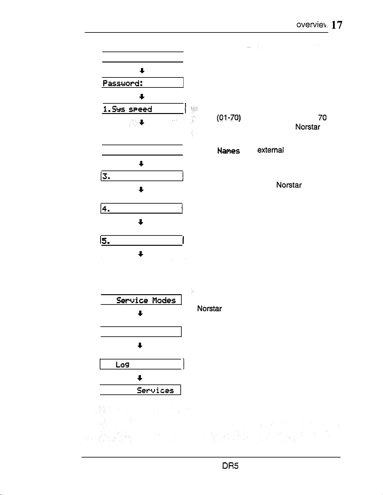
Administration
Administration programming has nine headings:
ADMINISTRATION CODE
dial
2.
Time and
date
Direct-Dial
Capabilities
System Speed Dial
code for fast dialing of up to
telephone numbers from any
telephone.
Names
telephones by name.
identifies lines and
Time and Date
date displayed on each
telephone.
Direct-Dial
that can be reached by dialing a single
digit.
Capabilities
abilities and telephone abilities. It
assigns restrictions and capabilities to
Class of Service (COS) passwords, to
telephones, to lines and to
line/telephone combinations.
designates the telephone
defines dialing filters, line
assigns a two-digit
adjusts the time and
6.
7. Password
8. Defaults
9. Call
Service Modes
system responds to calls,
depending on the time of day.
Password
controls access to Administration
programming.
Log Defaults
space for all telephones in the system.
Call Services
Call Display information at your
telephone.
controls how’ the
changes the password that
reallocates the Call Log
customizes the use of
Compact System Coordinator Guide
Page 76

18 Administration overview
Entering Administration
When your system is first installed, there is no password
stored
in the system. You are not prompted to enter a password
as you enter Administration for the first’time unless your
Customer Service representative has already programmed one
for your system.
To Enter Administration:
Release all calls’ on your telephone.
1.
Enter the Administration access code:
If the display changes to
3.
Password:
, enter the
Administratbn password. (The password is not shown on the
display as you enter it.)
If
the password is correct,
dial
, and three triangular indicators are
the display shows
shown on the vertical display.
If the password is incorrect,
Check the password. Press
password.
Place the Programming over the buttons.
4.
Exiting
any settings; you do not need to “save“ your changes.
1. Press
The display briefly shows
the display does not change.
and re-enter the
Administration
stores your changes automatically as soon as you alter
End of
session.
Compact
System Coordinator Guide
Page 77
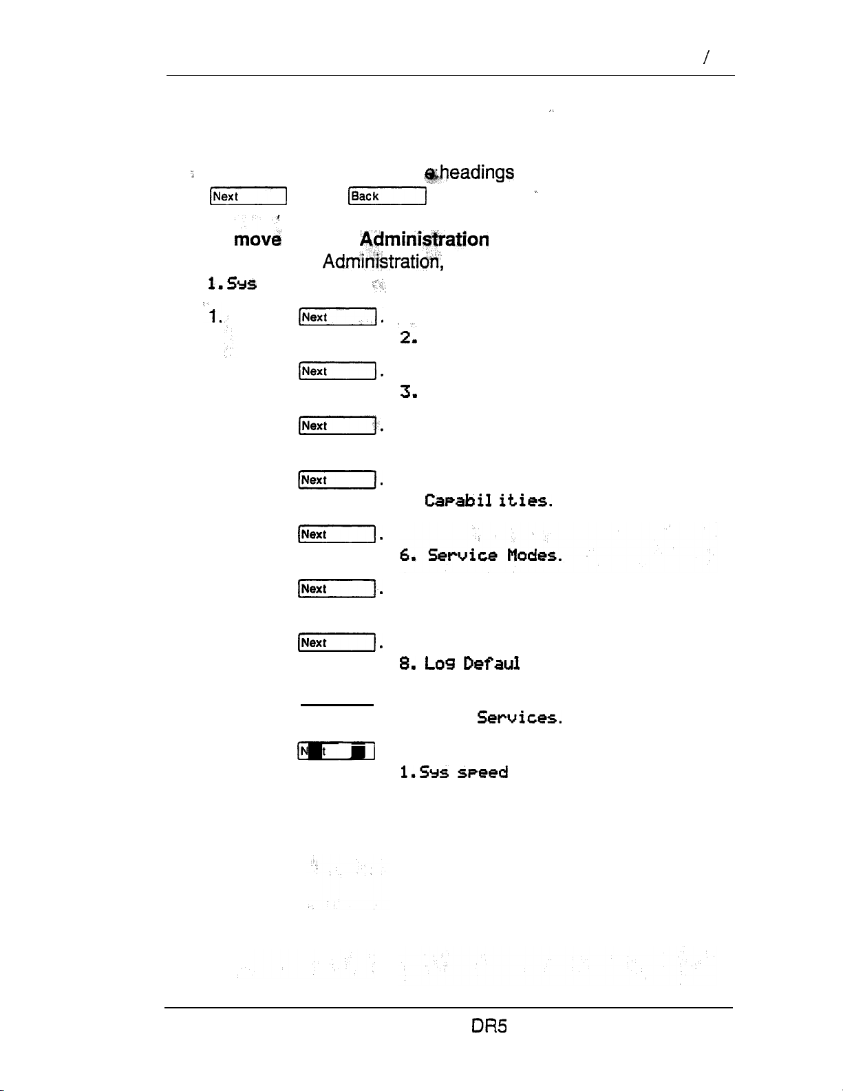
Administration overview 19
Moving through Administration
To program a setting, you must first locate the correct heading.
To do this, scan through th
and buttons.
.
To through headings:
After entering the display shows
speed
dial.
Press
The display shows
2.
Press
The display shows
Press
3.
The display shows
Names
Time
4. Direct-Dial.
of Administration using the
and date.
4.
Press
The display shows
Press
5.
The display shows
Press
6.
The display shows
7.
Press
The display shows
8.
Press
[Next].
The display shows
9.
Press
The display shows
5.
7. Password.
9. Call
.
ts.
dial.
Compact System Coordinator Guide
Page 78
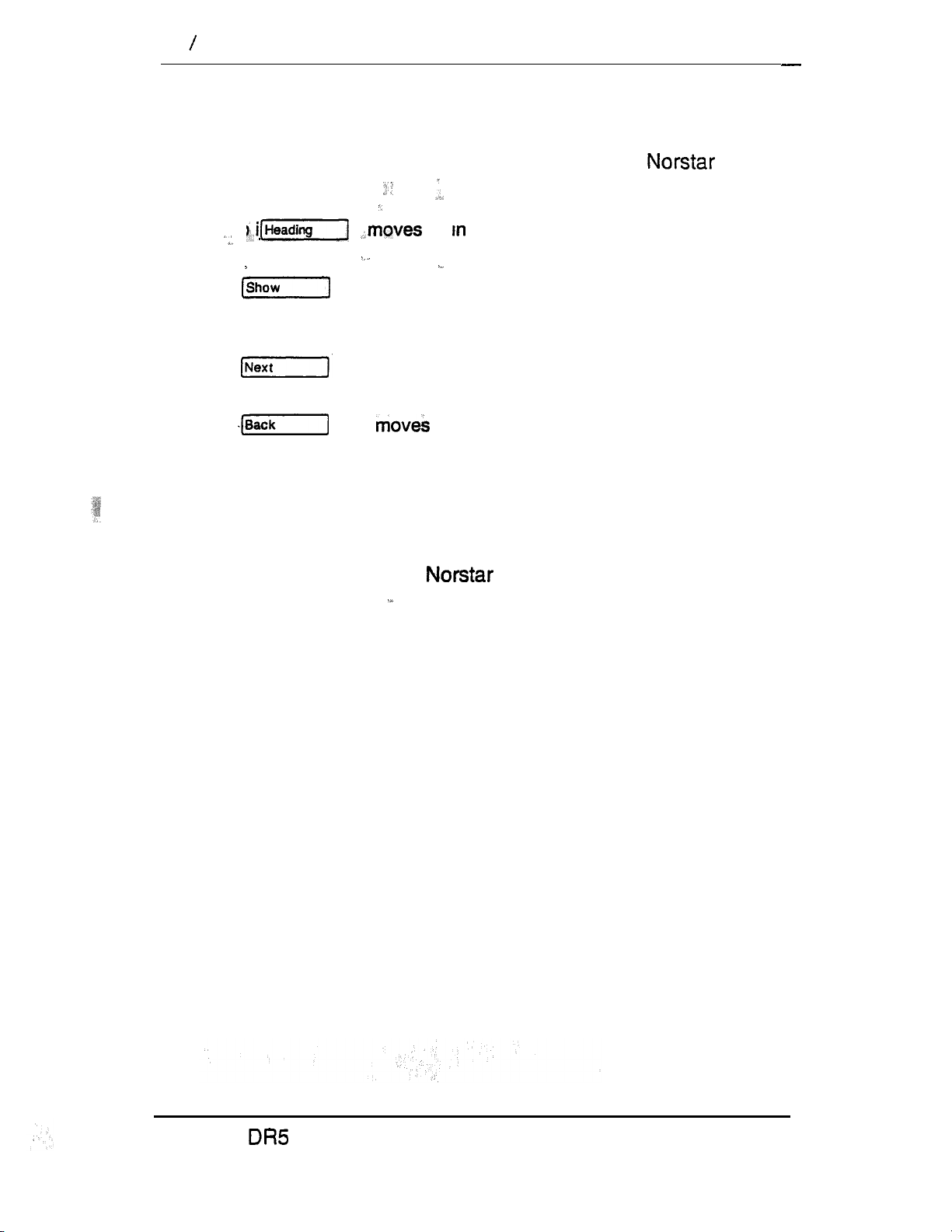
20 Administration overview
Using the Overlay
The indicators show
programming step. The functions on these buttons allow you
move through the headings and subheadings of
programming.
which buttons can be used at
that
to
subheadings.
up the hierarchy of headings and
moves down in the hierarchy of headings and
subheadings, or to begin programming settings
under a heading or subheading,
moves to the next heading, subheading, or
programmable setting.
to the previous heading, subheading, or
programmable setting.
Some of the functions identified on the Programming Overlay for
the M7208 Telephone are available on display buttons on M7310
and M7324 Telephones. For information about the additional
functions on the M7208 Telephone overlay, see the section in
this chapter entitled The display buttons.
Compact, System Coordinator Guide
Page 79
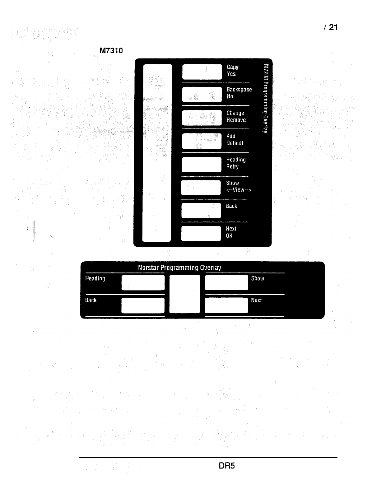
Administration overview
Programming Overlay for the M7208 Telephone (top) and for the
and M7324 Telephone (bottom)
Compact System Coordinator Guide
Page 80

22 Administration overview
The display buttons
Display buttons perform many functions. Depending on where
you are in programming, one, two, or three display buttons may
be available, at any one time. Press one of the display buttons to
select the function that you want.
The most common display button labels are:
Display message
Display button label
Display button
moves the cursor one space backward (backspace)
and delete a character, allowing you to re-enter a
number or letter.
copies line or telephone programming.
shows the last part of a displayed message longer
than 16 characters.
shows the first part of a displayed message longer
than 16 characters.
moves the cursor one position to the right when
programming a name.
moves the cursor one position to the left when
programming a name.
programmable setting.
Compact System Coordinator Guide
Page 81

Programming details
Entering numbers
Administration overview 23
Numbers are entered from the telephone
display button
Line numbers must always be entered as a two-digit number with
a leading zero. Internal telephone referred to as
Directory Numbers
may be used to edit the number.
are always two- digits long.
pad. The
Viewing long telephone numbers
External telephone numbers can be up 24 digits, but the
telephone display is only 16 character spaces long. If you wish to
see a previously programmed number that is longer than 16
digits, you must do the following:
Begin, for example, with
The display shows first 15 digits. The three dots at
the end of the display indicate that more digits remain
displayed for the external number.
1
To see the remaining digits, press
be
2.
To see the first 15 digits again, press
Compact System Coordinator Guide
Page 82

24 Administration overview
Entering names
Letters and numbers can be entered as part of a name for
various settings. The method of entering a name is always the
Begin with a prompts you to enter a name. The
display shows a
character; name:
,
Press the on the dial pad with the printed letter or
number that you want.
Each time that you press the button, a new character is
shown on the display. For example, the button for the
number 3 has the letters D, E, and F, where:
D is shown after the first press
E is shown after the second press
F is shown the third press
3 is shown
D is shown’ again after the fifth press.
(Letters are always shown in upper case.)
the fourth press
( ) to indicate where you can enter the
2.
When the character that you want is displayed,
press
position.
OR
if you want to correct a character entered by mistake,
press
character that you want to correct.
OR
If you want to the cursor back and delete a character,
press
3.
Repeat step 1 for the remaining characters.
or to move the cursor to the next character
or until the cursor is positioned beneath the
Compact
System Coordinator Guide
Page 83

System Speed
System Speed
The System Speed Dial programming section allows you to set
the Speed Dial codes for external telephone numbers which the
people in your office use most often. Use the Personal Speed
Dial feature to program numbers used
only one or two people.
3.
4. Direct-Dial
Capabilities
8.
9. Call
and
Defaults
Display digits
date
Speed name
restriction
You can program 70 System
to
Speed
Dial codes ranging from
Compact System Coordinator Guide
Page 84

26
System Speed Dial
System Speed Dial Number
System Speed Dial Number lets you assign a System Speed Dial
telephone number to a two-digit code. The System Speed Dial
Number may contain 24 digits.
Begin with the display showing
‘Press
The display shows
2.
Select the Speed Diai code you want to program:
Press
until the display shows the correct code.
1.
dial
dial.
OR
Enter the Speed Dial code on the dial pad.
To’assign default settings, press
press
Press
3.
4.
Press
.
For example, the display may show
Enter the new telephone number from the dial pad , including
5.
to go to the next Speed Dial code.
and then
all digits such as an initial or an area code that must be
dialed to call the number manually. If you need to backspace
the cursor, press the
BKSP
display button.
For example, press
The display shows
Press to store the System Speed Dial number.
6.
5551234,.
Programming hints
A Host System Signaling feature code may be inserted into the
System Speed Dial number. Run/Stop and Pause each use one
character position; and Link, Timed Release, and Programmed
Release each use two positions.
For more information on using these features in System Speed
Dial programming, see the Host System Signaling section in the
Telephones features chapter.
Compact DR5 System Coordinator Guide
Page 85

System
line Selection
Line Selection allows you to specify the external line that is used
for a System Speed Dial number. The options are the
line,
an external line, or a line pool.
After you have programmed a System Speed Dial number, press
and the display
‘Use 1
OR
Use
1
OR
Pool code: 42,
62,
for example, if a line is already assigned
for example, if a line pool access code is
already asslgned.
1.
To change the setting, press
until the display shows
the option to be programmed.
2.
If you select a line number or a line pool access code, enter
the digits from the dial pad. A line pool access code can be
from one to four digits long.
Prime
Display Digits
Display Digits determines whether the telephone number is
displayed when a System Speed Dial number is used, or whether
a name associated with that number is displayed.
After you have programmed a line selection for a System Speed
Dial number, press and the display shows
1.
Press
and N (No).
to change the setting. Options are Y (Yes)
Compact System Coordinator Guide
Page 86

28 System Speed Dial
System Speed Dial Name
System Speed Dial Name allows you to assign a name to the
stored System Speed Dial number. When the Display Digits
setting is “No”, the programmed name is shown on the
display when the System Speed Dial feature is used.
The name can be up to 16 characters long. The default name is
the System Speed Dial number; for example,
for System Speed Dial code 02.
Dial
After programming Display digits to
display shows
1.
Press
Name.
N,
press and the
The display shows the assigned or default name.
2.
Press
3.
Enter the first character of the name by pressing the
appropriate dial pad button one, two, three, or four times. For
more information, see the section in this chapter entitled
Entering names.
4.
To move the cursor to the next position, press
Continue entering characters.
Programming hints
You can program System Speed Dial Name only if Display Digits
is set to No.
Bypass Restrictions
Bypass Restrictions allows the System Speed Dial number to
bypass any restrictions in applied Dialing filters. Dialing filters are
programmed in the Capabilities section of Administration
programming.
After programming the System Speed Dial Name, press
and the display shows
Press
to change the setting. Options are N (No),
and Y (Yes).
Compact
System Coordinator Guide
N.
Page 87

Names
You can assign names to identify external lines and your
co-workers” telephones. During a call, the name (if programmed:
is shown on the telephone display instead of the external line
number or internal telephone number of the caller.
speed dial
6.
Service
Modes
Programming hints
Telephone names and line names can contain both letters and
numbers, but cannot be longer than seven characters. The
symbols cannot be used.
You can give the same name to two or more telephones, or to a
telephone and a line in your system. To avoid confusion, you
should avoid such duplication. Use initials, abbreviations, or ever
nicknames to give each telephone a unique name.
Two lines cannot have the same name. If you enter a line name
which has already been used, you hear an error tone, and the
display shows
Use unique
Compact System Coordinator Guide
Page 88

Telephone Names
Personalize your office communication by assigning names to
the telephones in the
is its internal number, for example, 27.
system. A telephone’s default name
Begin with the showing
speed
Press
The display shows 2.
2.
Press twice.
The display shows
3.
Enter the internal number of the telephone.
set:
OR
Press for the name of the telephone with the first
internal number.
4.
Press
The name is removed from the display, and a cursor is
shown.
5.
Enter the first character of the name by pressing the
appropriate dial pad button one, two, three, or four times. For
more information, see the section in this chapter entitled
Entering names.
Note:
Press to restore the default name and go
to the next internal number.
6.
Press
to move the cursor to the next position.
Continue entering characters.
Programming hints
If Automatic Telephone Relocation is turned ON, the name and
internal number of a telephone are saved if the telephone is
moved within your system.
Compact DR5 System Coordinator Guide
Page 89

Names
Line Names
Line Names allows you to assign a name to an external line. The
default name is the line number, for example,
Line
Begin with the display showing
Press
The display shows
Press
display shows
3,
Press
The display shows Line
4.
Press .
The display shows
5.
Enter the line number from the dial pad.
OR
Show 1
Press to program the name of line
6.
Press
The name is removed from the display, and a cursor is
shown.
speed dial .
01.
7.
Enter the first character of the name by pressing the
appropriate dial pad button one, two, three, or four times. For
more information, see the section in this chapter entitled
Entering names.
Press to restore the default name and go
to the next external line.
8.
Press
to move the cursor to the next position.
Continue entering characters.
Compact DR5 System Coordinator Guide
,
Page 90
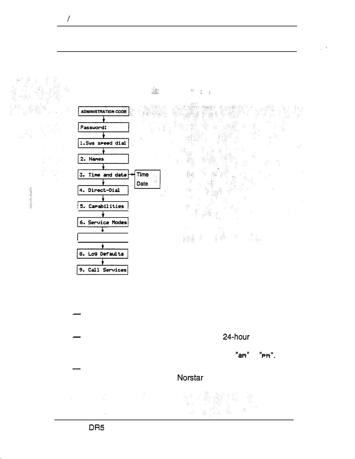
32 Time and date
Time and date
Time and date programming allows you to set the time and date
which is shown on the display when a telephone is not in use. As
with any clock, this needs to be done every time that your office
has a power failure;
7.
Password
8. Defaults
9. Call Services
I
Changing the time and date is easy, but there are a couple of
things to remember:
All times and dates must be entered using numerals. For
example, February would be entered as “2”.
The time may be entered in either 12 or format. If the
display is in English, and the hour entered is less than
thirteen, the display prompts you to specify or
The year is not shown on the telephone display, but make
sure that it is set correctly.
is programmed to allow
for leap years.
Compact System Coordinator Guide
Page 91
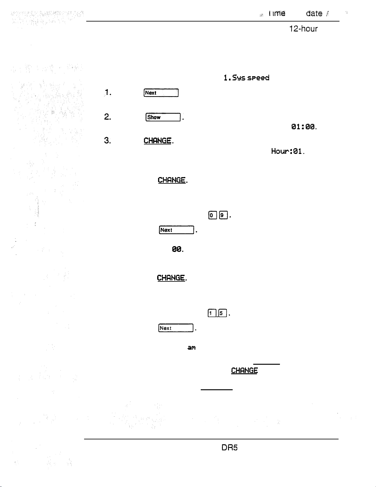
and
33
English language displays always show the time in
format, while the aiternate language displays always use the
24-hour format.
Setting the time
Begin with the display showing
dial .
Press twice.
The display shows
3.
Time
and date,
Press
The display shows the time, for example,
Press
Time
The display shows the hour, for example,
4.
Set the hour.
a. Press
A cursor replaces the number on the display.
b.
Enter the hour using the dial pad.
For example, press
c. Press
The display shows the minutes, for example,
Minutes:
5. Set the minutes.
a. Press
A cursor replaces the number on the display.
b.
Enter the minutes using the dial pad.
For example, press
c. Press
If the hour entered in step 5 is less than thirteen, the
display shows
.
6.
To switch the message to PM , press
To switch it back to
7.
To set the
date,
am
, press
press [Next].
Compact System Coordinator Guide
CHRNGE.
again.
Page 92

34 Time and date
Setting the date
Begin with the display showing
1. Press twice.
The display shows
2. Press
The display shows the time, for example,
3. Press
The display shows the date, for example, Date
and
dial .
Time
Press
4.
5. Set the year.
a. Press
A cursor replaces the number on the display.
b.
Enter the year using the dial pad.
For example, press
c. Press
The display shows the month, for example
6. Set the month.
a. Press
A cursor replaces the number on the display.
b.
Enter the month using the dial pad.
For example, press to enter February.
c. Press
The display shows the day, for example
The display shows
to enter the year 1990.
Year: 88.
81.
81.
7. Set the date.
a. Press
A cursor replaces the number on the display.
b.
Enter the date using the dial pad.
For example, press
Compact System Coordinator Guide
Page 93

Direct-Dial
Direct-Dial programming allows you to call the Direct-Dial
telephone assigned to your telephone by dialing a single digit.
Use the
directory number
Password:
2. Names
3.
Time
II
4. Direct-Dial
Direct-Dial
CODE
speed dial
and date
heading to specify the telephone
(DN) designated as the-Direct-Dial telephone.
Direct-Dial
8. Defaults
Use the button, the
display button and the
dial pad to enter the internal number of the telephone to be
designated as the Direct-Dial telephone.
Programming hints
To complete Direct-Dial telephone programming, assign a
Direct-Dial telephone to each telephone in the system using the
Capabilities section of Administration programming.
The digit you dial in order to get the Direct-Dial telephone to ring
can be programmed by your Customer Service representative.
Compact System Coordinator Guide
Page 94
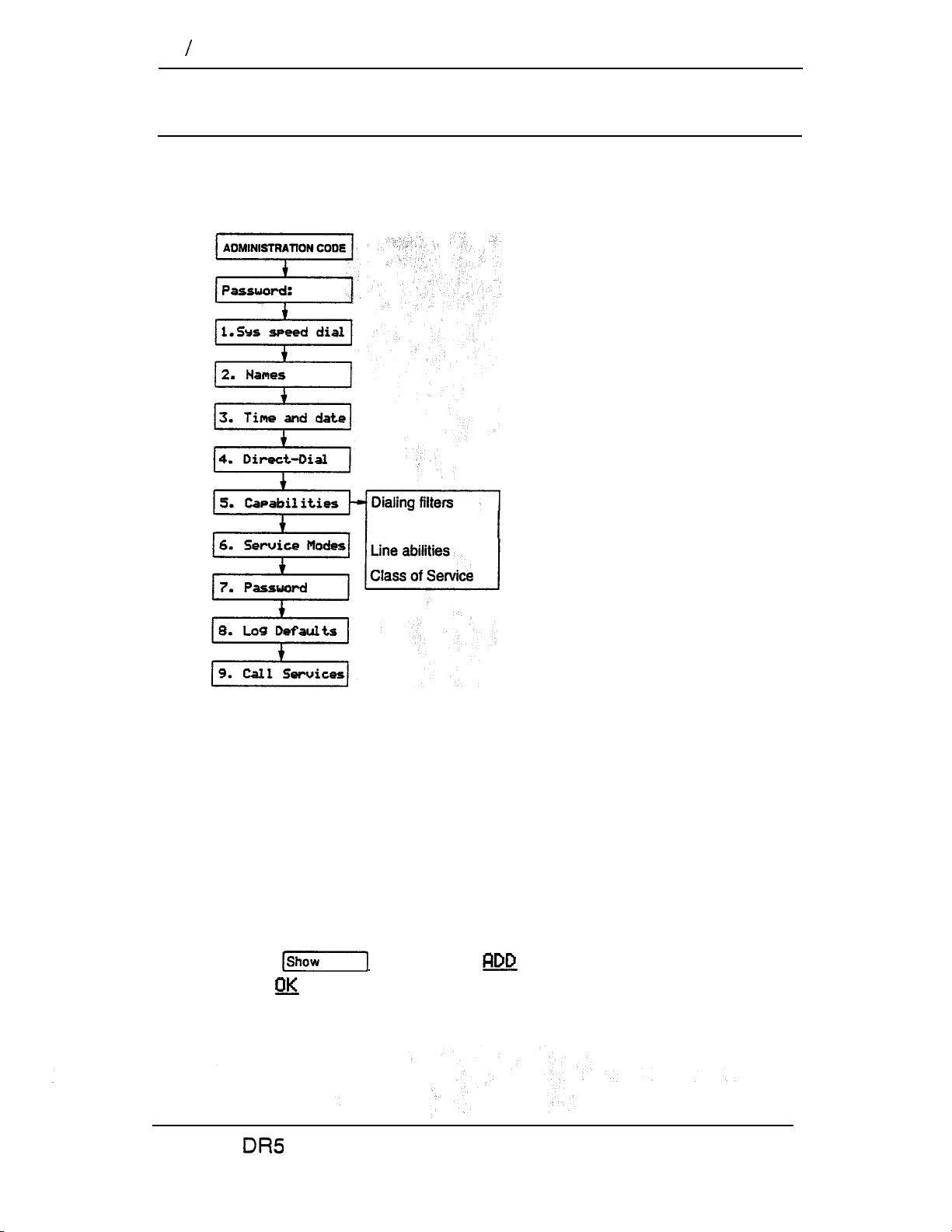
36 Capabilities
Capabilities
Capabilities programming assigns restrictions and exceptions to
Class of Service (COS) passwords, telephones, and lines.
Dialing Filters
A dialing filter is made up of restrictions and exceptions. These
specify the external numbers which can or cannot be dialed from
a telephone or on a line.
After dialing filters are defined, they may be used as telephone
(set) filters, line filters and line/set filters to manage outgoing
calls.
Use the button, the display button, the dial pad,
and the display button to program the restrictions and
Telephone abilities
exceptions for each dialing filter.
Compact
System Coordinator Guide
Page 95

For example
You may need filters for three different types of users:
Managers may require unrestricted dialing.
Secretaries may need to be limited to calls on line 003 to the
West coast office only.
- Clerks may need to be limited to calling specific area codes
and the West coast office:
Dialing filters are most commonly used to prevent unauthorized
long-distance calls, without restricting local calls. Dialing filters
restrict the numbers that an internal user can on external
lines.
a line/set filter has been defined for the line selected at the
user’s telephone, it overrides any line filters or telephone filters
which might otherwise apply.
If no line/set filters have been defined, dialed digits are filtered
through (and may be rejected by either the telephone filter (if
defined) and the line filter (if defined).
Compact System Coordinator Guide
Page 96

38 Capabilities
Programming hints
Filter 00 cannot be changed.
Each programmable filter can have up to 48 restrictions;
there is no limit on the number of exceptions that can be
allocated to any restriction. ,
There is a maximum of 200 restrictions and exceptions
allocated to the 23 programmable filters. For example, notice
the reduction in the number of available restrictions and
exceptions after each filter has been programmed.
Filter type
can have up to 24 dialing filters (00 to 23).
User
Rest’s
Remaining
00
01
02 clerk 7
Total
manager -- -- 200
I secretary 5
I
I
5
190
I
I 171
The maximum length for a restriction is 15 digits; for an
exception, the maximum is 16 digits.
The asterisk * is a “wild card” that stands for any digit.
Any restriction or exception can be used in any number of
filters. Each time it is used, it counts as one entry. For
411
example, if restriction
exists in filters 01, 02 and 03 it
uses up three entries of the 200 entries available.
Removing a restriction also removes the exceptions
associated with it, and changes the identifying number of the
restriction. For example, removal of restriction 01 renumbers
restrictions 01 to 48 as 01 to 47.
Note:
The removal of a restriction from one dialing filter
has no effect on the contents of other filters into
which the restriction was copied.
Compact DR5 System Coordinator Guide
--
Page 97

You cannot delete a filter. Removing the restrictions
programmed on a filter makes it an unrestricted filter but the
filter is not removed.
Fiiter descriptions
Filter 00 permits unrestricted dialing, and cannot be changed.
Filter 01 is pre-programmed with five restrictions and some
exceptions.
Filter
Restrictions
Exceptions
Filters 02 and 03, although not pre-set with restrictions and
exceptions, are the default filter settings used later in
programming:
Where the filter is programmed as a default
Filter
setting in Capabilities programming
03
Set abilities
I
Line
I
Set filter:
Line ter:
Compact System Coordinator Guide
Page 98

40 Capabilities
Telephone (Set) abilities
Telephone (Set) abilities programming assigns dialing filters and
permissions to telephones. Telephone abilities include:
Telephone (set)
Line/telephone filters
Lock,
Full Handsfree
Automatic Handsfree
Handsfree Answerback
Call Pickup Group
Paging
Page Zone
Auxiliary Ringer
Direct-dial telephones
Call Forward On Busy
Call Forward No Answer
Receive tones
Hotline
Priority Call
Telephone (Set) filter
A Telephone filter is a collection of restrictions and exceptions
defined in Dialing filters. These filters are applied to telephones
through Set filter programming.
Use the button, the display button and the
dial pad to enter the number of the Dialing filter to be assigned as
the Telephone filter.
Filter 02
is the default set filter.
Line/telephone (Line/set) filter
A Line/telephone dialing filter applied to the appearance of a
line at a
or Telephone filters which might otherwise apply.
Line/set filters control the numbers that may be dialed on specific
external lines from specific telephones. For example, a Line/set
filter can permit a call to a specific long-distance number on
line 03 from a specific telephone, but no other long-distance
numbers, and on no other line.
Use the (Show] button, the’ display button and the
dial pad to enter the number of the Dialing filter to be assigned as
the Line/telephone filter.
telephone. This type of filter replaces any Line
Compact
System Coordinator Guide
Page 99

Programming hints
Up to 24 filters may be defined in the system (filters 00 to
23). Line/set filters fall under this limitation.
A maximum of 255 Line/set dialing filters may be applied to
lines at telephones.
Telephone* Administration
Telephone Administration Lock limits the types of features that
may be used or programmed at a telephone. Use the
display button to select one of the three options: None, Partial
and Full.
None
Partial
l
allows you to access any feature on your telephone.
prevents:
programming buttons
programming Personal Speed
Dial numbers
l
programming feature buttons
moving line buttons
l
changing the display
language
Full,
in addition to the restrictions outlined for Partial lock,
prevents:
changing Background Music
l
changing Privacy
l
changing Do Not Disturb
l
using Ring Again
. . .
l
changing Dialing Modes
(Automatic Dial, Pre-Dial, and
Standard Dial)
using Voice Call Deny
l
using Administration
programming
l
saving a number with Saved
Number Redial
using Call Forward all calls
l
l
using Send Message
l
using Trunk Answer
l
activating Service Modes
Full Handsfree
Full Handsfree allows you to make or receive calls without
picking up the receiver, and allows a headset to be used with the
telephone. Use the
setting: N (No) or (Yes).
Compact System Coordinator Guide
display button to select the
Page 100
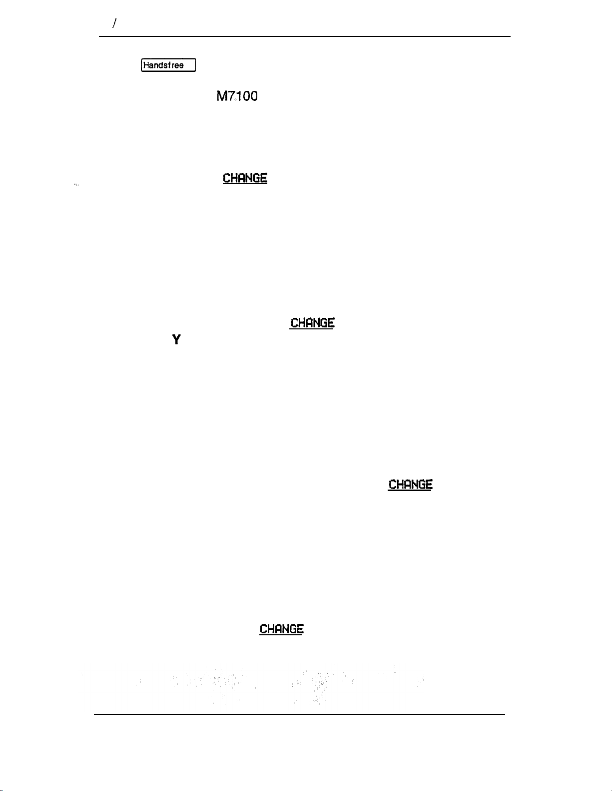
42
Capabilities
Programming hints
A button is automatically assigned to a telephone that
is programmed with Full Handsfree. Full Handsfree is always
disabled for an Telephone.
Automatic Handsfree
Automatic Handsfree activates the Handsfree microphone and
speaker when you make or receive calls by pressing a line
button. Use the
N (No) or Y (Yes).
Programming hints
You can program Automatic Handsfree only if the telephone has
Full Handsfree set to Yes.
Handsfree Answerback
Handsfree Answerback allows you to answer a Voice Call without
lifting the receiver. Use the
display button to select the setting:
display button to select the
setting: (Yes) or N (No).
Programming hints
Handsfree Answerback is always disabled for an M7100
Telephone.
Call Pickup (Group)
Each telephone can be assigned to one of up to nine Call Pickup
groups. Members of a Call Pickup group can answer any calls
ringing at a telephone in the group. Use the
display
button to select the setting: NO, 1, 2, 3, 4, 5, 6, 7, 8, or 9.
Programming hints
You cannot pick up a call that is on a Private line, or a call that is
ringing only the Auxiliary Ringer.
Paging
This setting determines whether a telephone has access to the
Page feature. Use the
display button to select the
setting: Y (Yes) or N (No).
Compact DR5 System Coordinator Guide
 Loading...