

Page 1
_I_
-.
StarTalk Mini Installation Guide
-c
Page 2

Table of
Contents
Introduction
Ports vs channels
Before you start
Compatibility check list
Package check list
Environment check list
Electrical check list
Special parts check list
Installation check list
installing the module
Mounting steps
Connecting the module to the KSU
1
1
1
2
2
3
4
5
6
7
8
10
and connecting the power supply
Preparing to initialize
Initializing
Connecting a printer to the Mini module
Printer check list
communication parameters
Connecting an RS-232 terminal
Determining Feature Codes
11
12
13
16
16
17
17
18
Page 3
Page 4

FCC Regulations
This equipment complies with Part 68 Rules and Regulations
of the FCC Regulations for direct connection of the public
switch telephone network.
Radio frequency interference
Warning:
This equipment generates, uses, and can radiate
radio frequency energy, and if not installed and used in
accordance with the instruction manual, may cause interfer-
ence to radio communications. It has been tested and found
to comply with the limits for a Class A computing device
pursuant to Subpart J of Part 15 of the FCC Rules and CSA
specification
08.8,
which are designed to provide reasonable protection against such interference when operated in a
commercial environment. Operation of this equipment in a
residential area is likely cause interference in which case
users will be required at their own expense to take whatever
measures necessary to correct the interference.
This apparatus does not exceed the Class A limits for radio
noise emissions from digital apparatus set out in the Radio
Interference Regulations for the Canadian Department of
Communications.
CAUTION:
The Mini module contains
fragile
electronic parts. It weighs 2.2 kg (approximately 5 Ibs).
DO NOT DROP OR BUMP THE MODULE.
,
Unit must be powered from a class 2 power source UL
and CSA listed.
Page 5

In the event of equipment malfunction, all repairs will be
performed by Northern Telecom or by one of its authorized
dealers.
Address of repair facilities
USA:
Northern Telecom Inc.
Nashville Repair Distribution Center
640
Drive
Nashville, TN 37210
Attn.
Tel: (615) 883-9220
Canada:
Northern Telecom Canada Ltd.
Telecom Service Division
12345 Albert Hudon Blvd.
Montreal North, Quebec
Attn: Customer Service, Dept. 0914
Tel: (514) 324-2020
Page 6

Mini Installation Guide
The Mini module has the following:
1
l
.
.
.
The Mini module is connected to the KSU
vs
channels
through the station port. The station port is capable of having
either two voice or a voice and data conversation
ously. The two voice channels are referred to as the and
of the Station port. This provides with the
capability of handling two calls simultaneously on the port.
Before
you start
90 minute Message Storage Pack
two-voice channels/one-port
no replaceable parts
an external power supply
channels. uses the and channel capability
Read this guide.
Make sure the compatibility conditions are met. A
Compatibility check list
guide.
is provided on page 2 of this
u
U
Make sure all the equipment in the package is
accounted for. A
in this guide.
Make sure the environment and electrical conditions
are met. An
are provided later in this guide.
list
Make sure you have the necessary tools to complete
the installation. A
provided later in this guide.
Make sure you are familiar with the steps required to
install An
later in this guide.
Make sure you know the Feature Codes. For
more information about Feature Codes, refer to
Package check list
Environment
and an
Electrical check
Special parts check list
Installation check list
is provided later
is
is provided
Determining Feature Codes.
Page 7
2
Mini Installation Guide
Compatibility
equipped with:
is compatible with Compact (6 x 16)
DR2 software
DR5 software
is compatible with Modular (8 x
equipped with:
software version 5.2 or greater
DR3 software
DR4 software
DR5 software
software
To determine the software type and version of the
KSU, refer to
version.
Package
Make sure the package contains:
check list
software
Determining the KSU software type and
the Mini module
a power supply
an RJ-11 teladapt connection cord
a shrink wrapped package of documentation
Page 8

Mini Installation Guide
The installation area should be:
3
check list
U
u
clean, free of dust, dry and well ventilated
between
Fahrenheit)
non-condensing relative humidity between 8% and
at least 4 m (approximately 13 ft) from equipment such
as copiers, electrical motors and other equipment that
could produce electromagnetic, radio frequency and
electrostatic interferences
a wall area approximately 1 m square (approximately
sq)
3
within 305 m (approximately 1000 ft) of the
KSU
and 40” Celsius (approximately to 105”
within 2 m (approximately 6 ft) of a three-wire
grounded electrical outlet
a minimum of 16 cm (approximately 6 in) from a corner
wall or other component
a minimum of 46 cm (approximately 18 in) from the
floor
Note: The distance from the floor should be enough to
prevent water damage.
Page 9

4 Mini Installation Guide
Electrical
The electrical requirements for the Mini module are:
check list
Note: The Mini module does not require a dedicated circuit. DO NOT the module to an outlet on a
circuit that is likely to be overloaded or used by large office
equipment or power tools.
for 10 V product
voltage 115 VAC nominal (105 to 132 volts)
for the
voltage 220 VAC or 240 VAC nominal
(180 to 263 volts)
frequency Hz nominal (47 to 63 Hz)
current 0.5 Amps maximum
3rd wire ground
V product
Page 10
.
Mini Installation Guide
5
TO begin an installation, you need:
check list
u
u
U
u
U
screwdriver or power drill
anti-static grounding strap
two x 20 mm x wood screws (power
two x 20 mm x wood screws (module)
one modular telephone jack
twisted pair station wire
plywood backboard 2 cm thick
surge protector (recommended)
terminal or RS-232 printer and RS-232 printer
cable (optional)
Guide*
Note: equipment is not supplied with the Mini
module.
You might need this guide for instructions on installing a
station port in the event there are no free station ports
available at the distribution block.
Page 11
6
Mini Installation Guide
Installat
check
list
Installing a Mini module means you must:
Install the module
mount the unit to the wall
.
connect the station port
.
mount the power supply
l
connect the power supply
Initialize
Connect a terminal or printer if required (optional)
Determine the Feature Codes
Set the Date and Time
Name the port
Page 12
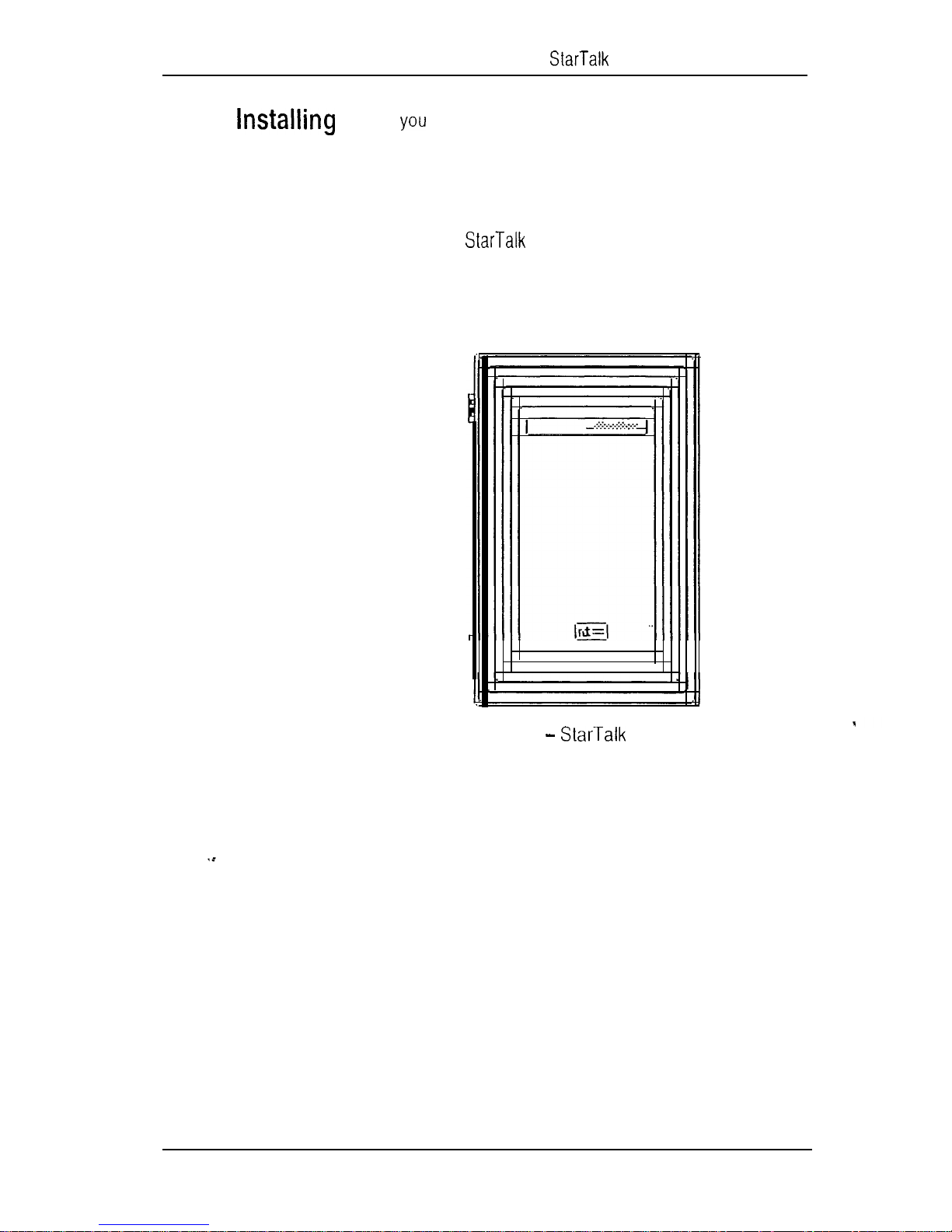
After have verified the environment conditions and your
the module
equipment, select a location for the module that is close to
the KSU, in a place free of traffic. The area should be free of
dampness and dust.
Mini Installation Guide 7
Warning:
and contains fragile electronic components.
bump the module.
The Mini module weighs 2.2 kg (5 Ibs)
Do not drop or
Figure 1 Mini
Page 13
8 Mini Installation Guide
--
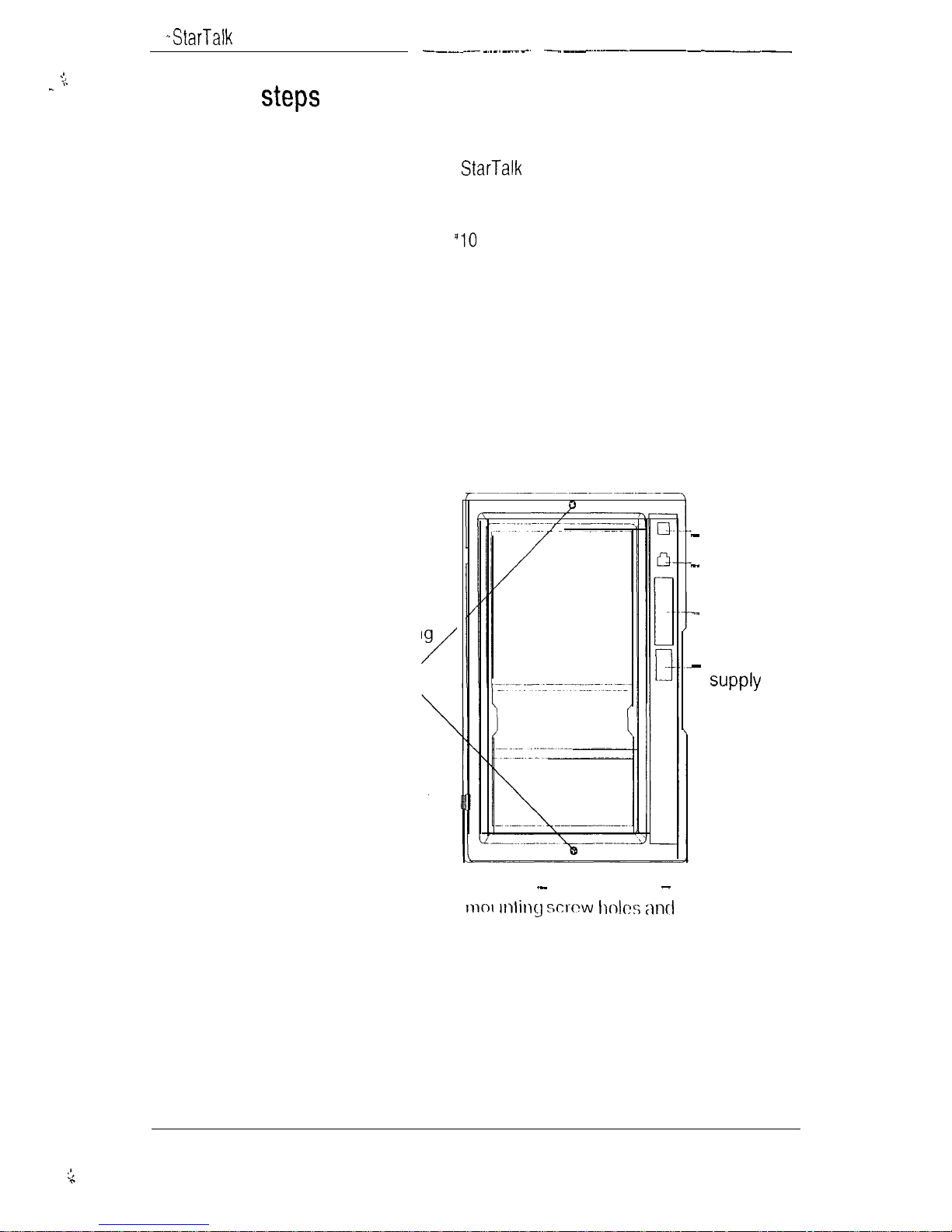
Mounting
You must open the door of the unit before you can mount the
module. To mount the module:
1.
Hold the Mini module against the plywood
backboard next to the KSU.
2.
Install a wood screw in the top screw hole, but do
not tighten it completely.
3.
Make sure the module is level. Install and tighten a
wood screw in the bottom screw hole.
4.
Tighten the top screw to secure the module.
You are now ready to connect the module to the KSU.
LED
Mounting
screw
holes
Figure 2
connectors
Stat-Talk Mini
Teladapt
jack
25 Pin
connector
Power
connector
Page 14
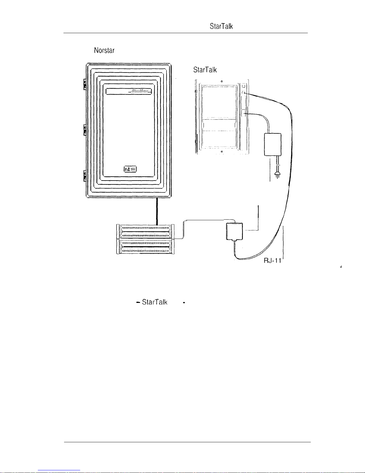
Compact KSU
Mini Installation Guide
Mini module
Power supply
9
Figure 3
Distribution
block
Mini
RJ-11 teladapt
jack
teladapt
cord
installation overview
Page 15

10
Mini Installation Guide
the
module to the
-- --- --
Before you start connecting the module, make sure one
station port is available at the distribution block. For
Instructions on installing a station port, refer to the
installation Guide
that came with the KSU.
IMPORTANT:
DR2 KSU using software version 5.2, DO NOT connect
to station ports 107, 121, 312, 512, or 712.
To determine the software version, refer
If you are installing on a Modular
lo Determining the
KSU software type and version.
To wire the module:
1.
2.
3.
4.
Locate the distribution block.
Make sure there is one available station port at the
distribution block.
Mount the RJ-I 1 teladapt jack next to the distribution
block.
Using twisted pair station wire, connect the teladapt
jack to a free station port on the distribution block.
5.
You are now ready to connect the power supply.
Test the port using a working telephone.
Connect one end of the RJ-11 teladapt connection
cord to the station port at the side of the module.
Connect the other end to the jack at the RJ-11 teladapt
jack. Do not use a teladapt cord that is longer than
4.5 m (approximately 14
Page 16
Mini Installation Guide
11
Mounting Y
ou must open the door of the unit before you can mount and
connect the power supply. To mount the power
connecting the
power supply
Connecting the power supply turns ON the power to the
2.
3.
The red power Light Emitting Diode (LED) on the module
should light up. If the LED does not light up:
4.
Using two wood screws, secure the power supply to
the backboard next to the Mini module.
Mini module. To power on the module:
Plug the five pin connector into the receptacle located
on the right side of the module.
Plug the three-prong plug into a grounded, electrical
outlet.
Verify there is power at the AC end of the power
5.
6.
This completes mounting and connecting the power supply.
You are now ready to begin initializing
If there is power at the AC outlet, verify there is power
at the DC end of the power supply.
If there is power a the DC end of the power supply,
replace the Mini module.
, Unit must be powered from a class 2 power source UL
.
and CSA listed.
Page 17
12
Mini Installation Guide
Initializing establishes:
initialize .
.
.
.
Before you begin:
the DN digit length to match the DN length
the primary and alternate languages of the
voice prompts
if the Group List option is enabled
the leading digit for Group (if the Group List
option is enabled)
Know the
DN length, go to any
and The DN appears.
Count the number of digits in the DN.
Important:
software, you must set the DN type of the
DN to be Only’ before you initialize
For instructions on setting the DN type, refer
to the
DN length. If you do not know the
telephone and press
If you are using with
Installer Guide.
Determine if the system is using the bilingual language
capability.
Know the primary and alternate languages to be used.
Know if the Group List option is enabled.
Know the leading digit for Group Lists. The Group List
leading digit default is nine.
Determine the
Note:
you must use a M7310 or M7324 telephone.
For information about Feature Codes, refer to
Determining Feature Codes
Mini Programming Record.
Feature Codes.
or the
To initialize
Page 18
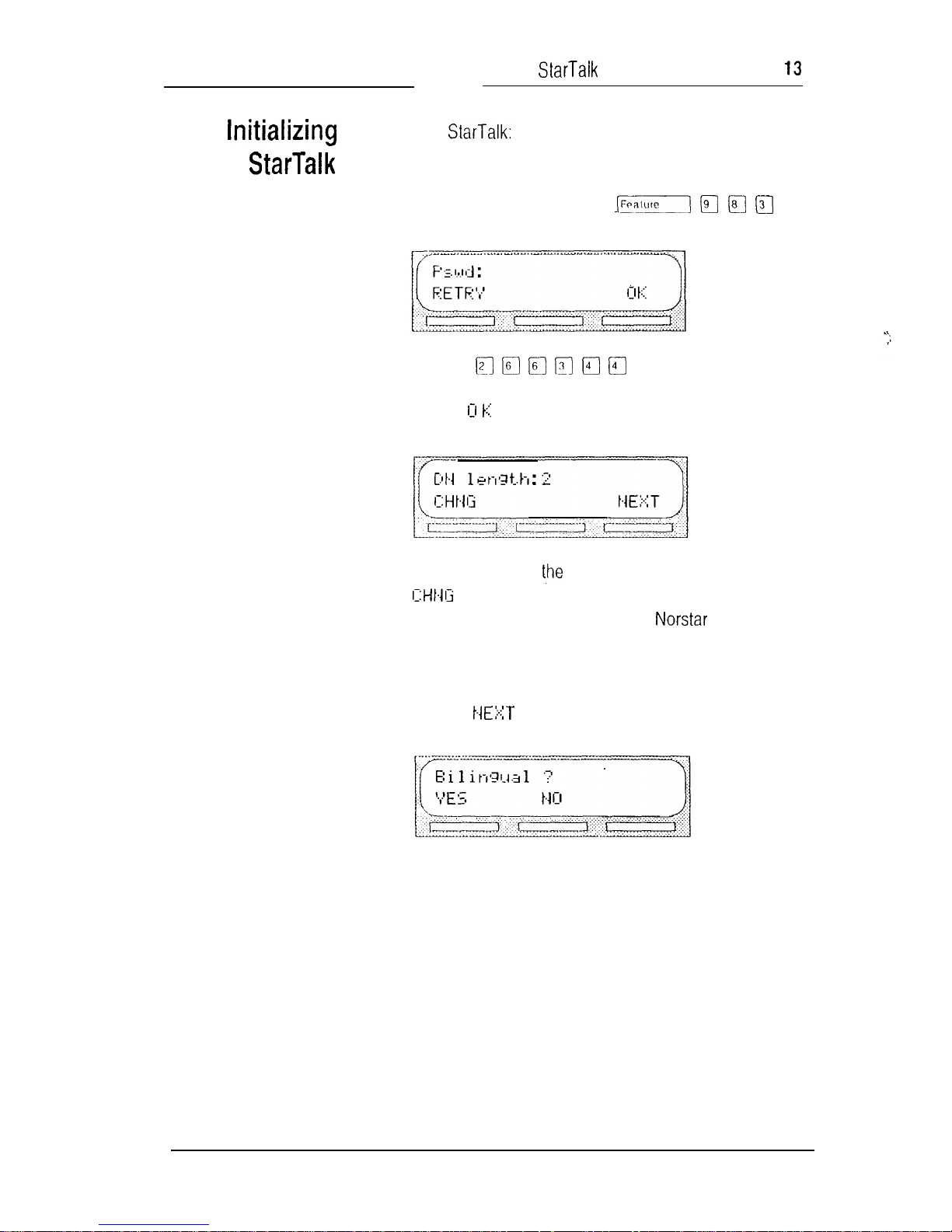
TO
-----
initialize
Mini Installation Guide
,
2.
3.
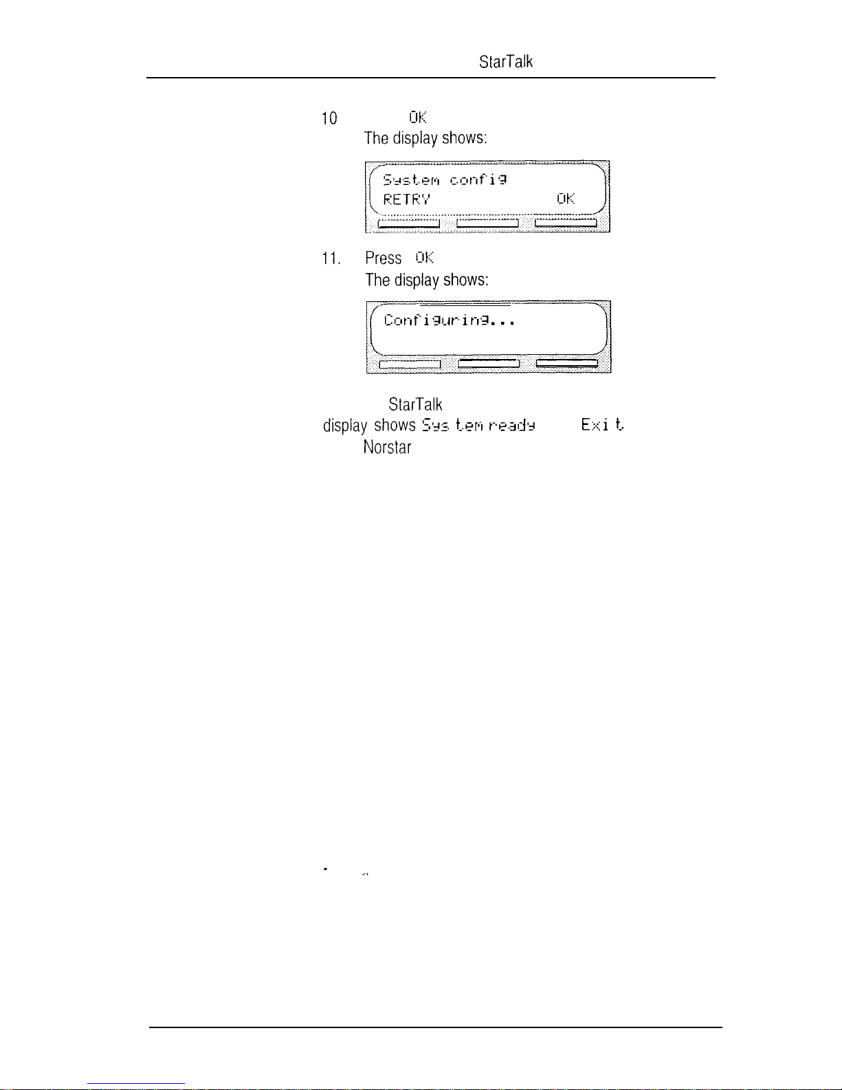
Enter the System Administration Feature Code.
Note: The default code is
The display shows:
Enter
Press
(CON
FIG)
The display shows:
Note: To change
and enter the new DN length. The mailbox DN
length MUST be the same as the
mailbox number length, press
DN length.
The mailbox number range is between two and seven
digits.
4.
Press
The display shows:
Page 19
14
Mini Installation Guide
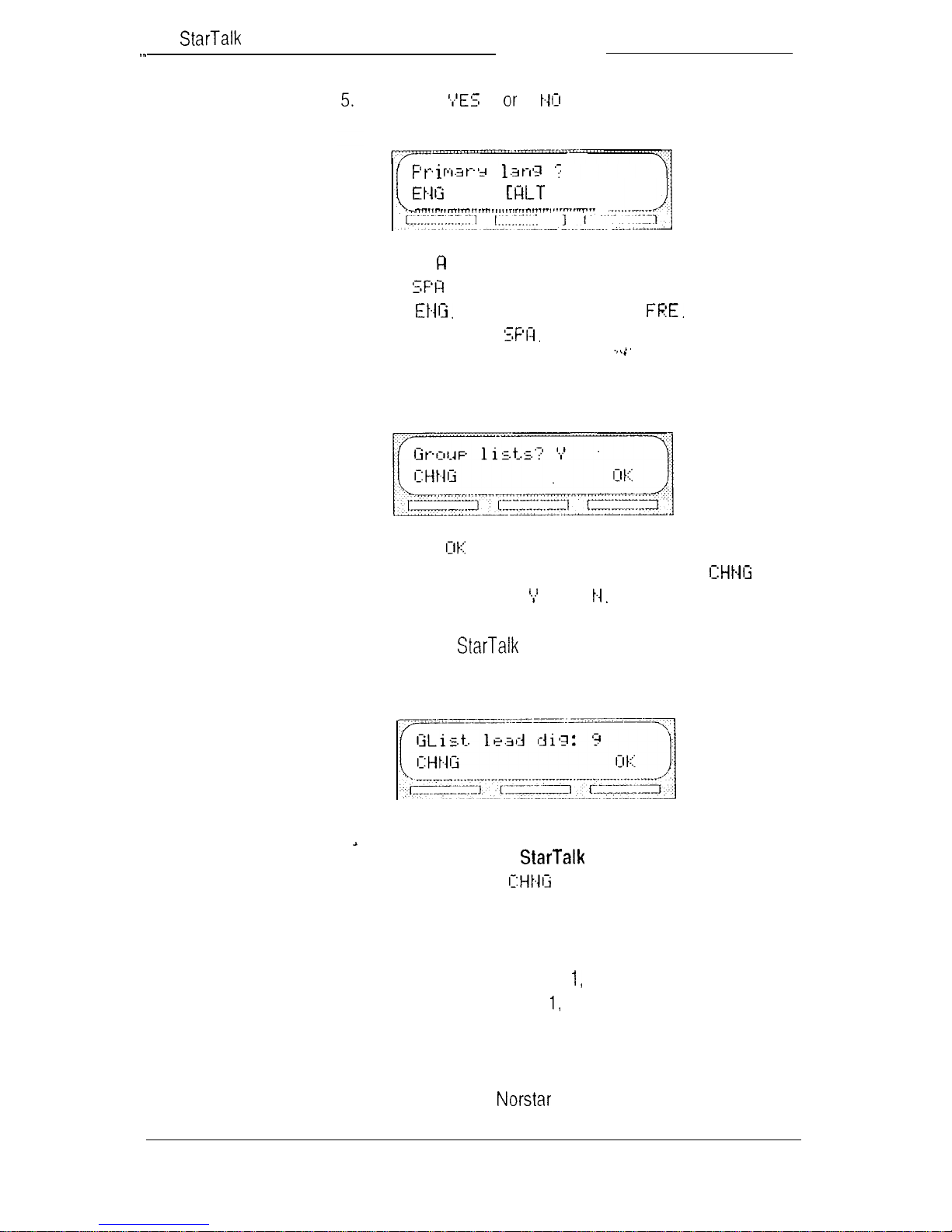
6.
Press
The display shows:
. . .
Note: L T
1
represent French or Spanish. Either FEE
or appears on the display. English is abbreviated
as French is abbreviated as Spanish is
abbreviated as
Select the primary language.
The display shows:
7.
Press to enable Group Lists.
Note:
If group lists are not required, press
This changes the to an
Caution:
If you disable Group Lists, you must re-
initialize to re-enable Group Lists.
The display shows:
Note:
If 9 is not the Leading Digit for Group Lists
indicated on the
Record,
press and enter the Group List
Mini Programming
number.
Important:
The Group List Leading Digit can be any
number from 0 to 9. The Special Mailbox numbers
automatically begin with so if you select a Group
List Leading Digit of the Special Mailbox numbers
will begin with 2. For example, the System Coordinator mailbox would be 22. The Group List Leading Digit
cannot be the same as the first number of the mail-
boxes on the system.
Page 20
Mini Installation Guide
Press to enable the Leading Digit.
15
When the
initial configuration is completed, the
to the date and time.
and then returns
Page 21
16
Mini Installation Guide
printer to the
Mini
Connecting and using a printer to print Reports is
optional. If a printer is not required, proceed to
communication parameters.
make sure you have an
a printer, we recommend using a ribbon cable
connector.
Before you install the printer,
cable. If you are connecting
Printer check list
The printer specifications
the printer. These are:
You must open the door of the unit before you can connect
the printer. To connect a printer:
1.
must be
serial printer type
Note:
unless a serial to parallel interface is used.
printer speeds must support 300 baud
hardware and software compatibility
Note:
are terminated by line feed/carriage return.
cable type must be straight through
Plug the male end of the cable into the
port.
does not work with a parallel printer
supports and all reports
met before you connect
2.
Important:
standard RS-232 connector. Make sure you use an appropriately constructed cable to connect the printer to the
Mini module. For more information, refer to
.
Tables.
Plug the female end of the RS-232 cable into the
modem port, located at the back of the printer.
The Mini module RS-232 port is
Figures and
a
Page 22

k
The communication parameters are fixed and
communication
cannot be changed. The communication parameters are:
Mini installation Guide 17
parameters .
Connecting an
W-232 terminal
300 baud
.
.
.
For the FE-232 terminal to communicate with
terminal parameters must be set to match the
parameters.
Note: When configuring the terminal,
carriage return.
For instructions on setting the RS-232 terminal communication parameters, refer to the instruction manual that came
with the terminal.
You must open the door of the unit before you can connect
the terminal. To connect the RS-232 terminal to
7 data bits
1
stop bit
even parity
the
supports
1.
Pin 2 on one end is connected to pin 2 on the other
end, pin 3 on one end is connected to pin 3 on the
other end, and pin 7 on one end is connected to pin 7
on the other end. The end of the cable attached to
must be male. For more information,
Figures and Tables.
2.
3.
The RS-232 parameters must be set to match the
Mini default parameters.
Attach the RS-232 cable to the KS-232
connector.
Attach the other end of the cable to the modem
connector on the terminal.
Page 23
18
Mini Installation Guide
Determining
The default Feature Codes for are 980 through 986,
inclusive. When these codes are used by other
applications or products (i.e. PCI, Hourglass, or
SMDR
) assigns Feature Codes between and
to These codes might not be assigned in sequential
order.
To deterrnine the Feature Codes:
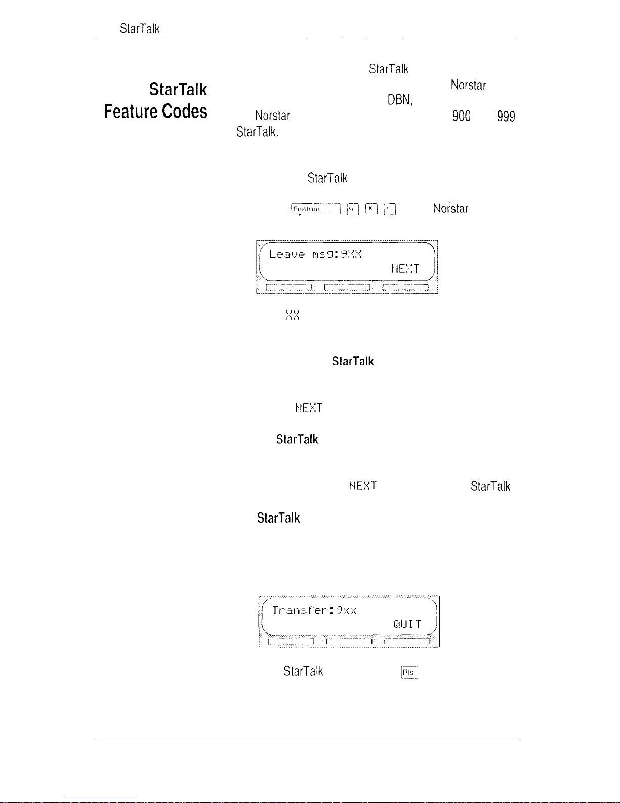
1.
Press on a M7310
or M7324 telephone. The display shows:
2.
Note:
Record the Feature Code for the Leave Message
Feature on the
and
represents a number between 00 and 99.
Mini Programming Record,
Figures and Tables,
Table 4.
3.
Press The display shows the Feature Code
for the Open Mailbox Feature. Record this code on
the
Figures and Tables,
4.
Continue pressing to show all of the
Feature Codes. Record each Feature Code on the
Figures and Tables,
When you reach the final Feature Code the display
shows:
To end this
Mini Programming Record,
Table 4.
Mini Programming Record,
and
Table 4.
session, press
and
Page 24
Determining the
TO
determine the
Mini Installation Guide
DN:
19
DN
1.
Enter the Directory Number Code.
Note: The default code is
The display shows:
Note:
To end this
represents the directory number
session,
Page 25

20 Mini Installation Guide
Date and Time
The Date and Time is independent of the
Date and Time, and must be set after you initialize
The Date and Time is part of the envelope
information that is stamped on incoming messages. The date
and time stamp also indicates to
To set the date and time:
2.
which greetings to
Enter the Date and Time Feature Code.
Note:
The default code is
The display shows:
Note: This number depends on the mailbox number
length being used. For example, if the mailbox
number length is six, you would enter 1000020000.
The mailbox number and default password combination for each mailbox number length are shown on
Figures and Tables,
Table 3.
3.
4.
Press
The display shows:
Press
The display shows:
Page 26
Mini Installation Guide
21
5.
6.
7.
8.
Enter year, month, and day>
Note: This is a six-digit field. Any single month or day
must have a zero
number. For
example, June 4, 1992 must be entered as 920604.
Press
The display shows:
Press
The display shows:
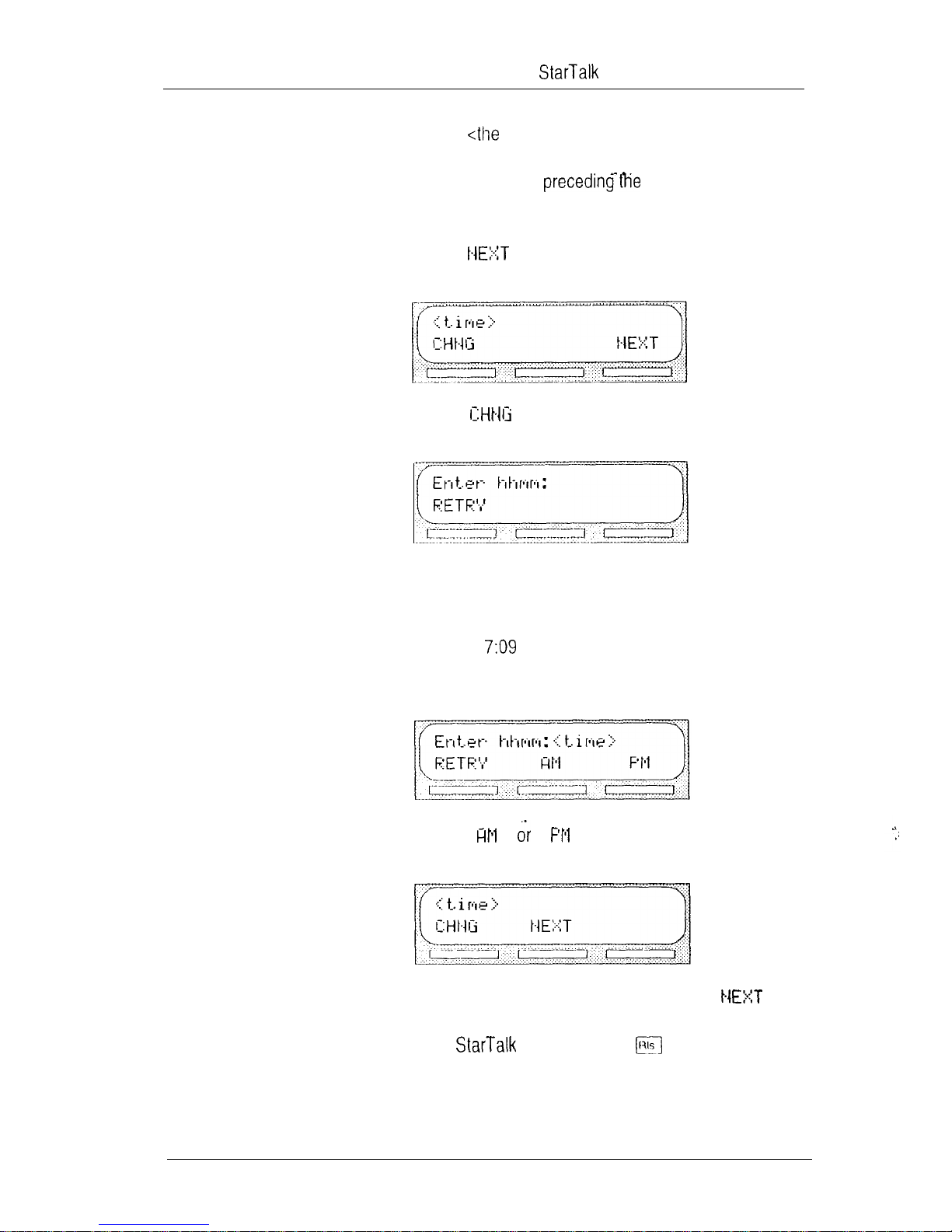
Enter <the time in hours and minutes>
Note: This is a four-digit field. Any single hour or
minute must have a zero preceding the number. For
example,
must be entered as 0709.
The display shows:
9.
Press
The display shows:
Note: To return to the date display, press
To end this session, press
Page 27

22 Mini Installation Guide
Using
with
software
Naming
port
k
and
After the installation and initialization are completed, we
recommend you use
rename the
Note: For more information, refer to the
Guide
When you use a
and Centrext software, you must program parameters correctly to ensure
ing the
thresholds are the two most important parameters. To check
other
that came with the KSU.
Mini Set Up and Operation Guide, Appendix A.
station port to:
DN type and setting and
and Centrext feature compatibility, refer to the
Configuration programming to
Installation
Mini module with
operates properly. Assign-
Important:
designate the DN as only’. For instructions
about determining the DN, refer to
assigning the DN type, refer to the
Installer Guide
When you are using with
and Centrext software, you must ensure you
Determining the
DN,
earlier in this guide. For instructions about
or
Centrext Installer Guide.
Page 28
Mini Installation Guide 23
Trouble-
shooting
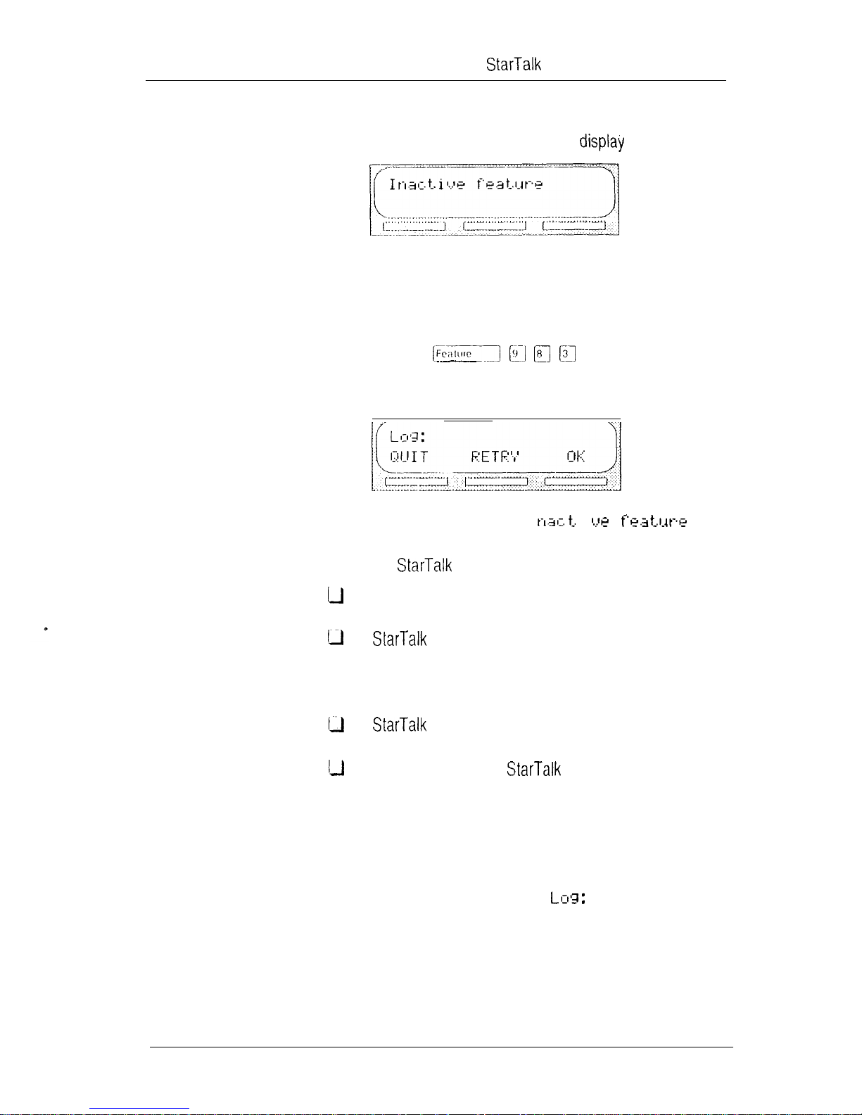
Troubleshooting the Star-Talk installation is needed if you
attempt to initialize the system and the shows:
Should this occur:
1.
Check the wiring at the distribution block, then enter
the System Administration Feature Code. The default
code is
The display should show:
2.
If the display still shows I
disconnect the AC power and check all the wiring for
the
Mini module. Make sure the:
i
power supply is connected and plugged in
Mini module has had the necessary time to
complete the three to five minute self testing
procedure
is connected to a working station port
power source to the
damaged
3.
Note
not operational, unmount and repackage the module, and
return it to your distributor.
After checking all the wiring, reconnect the power.
Wait three to five minutes and enter the System
Administration Feature Code.
The display should show:
If you have checked the wiring and the module is still
Mini module is not
Page 29
24 Mini Installation Guide
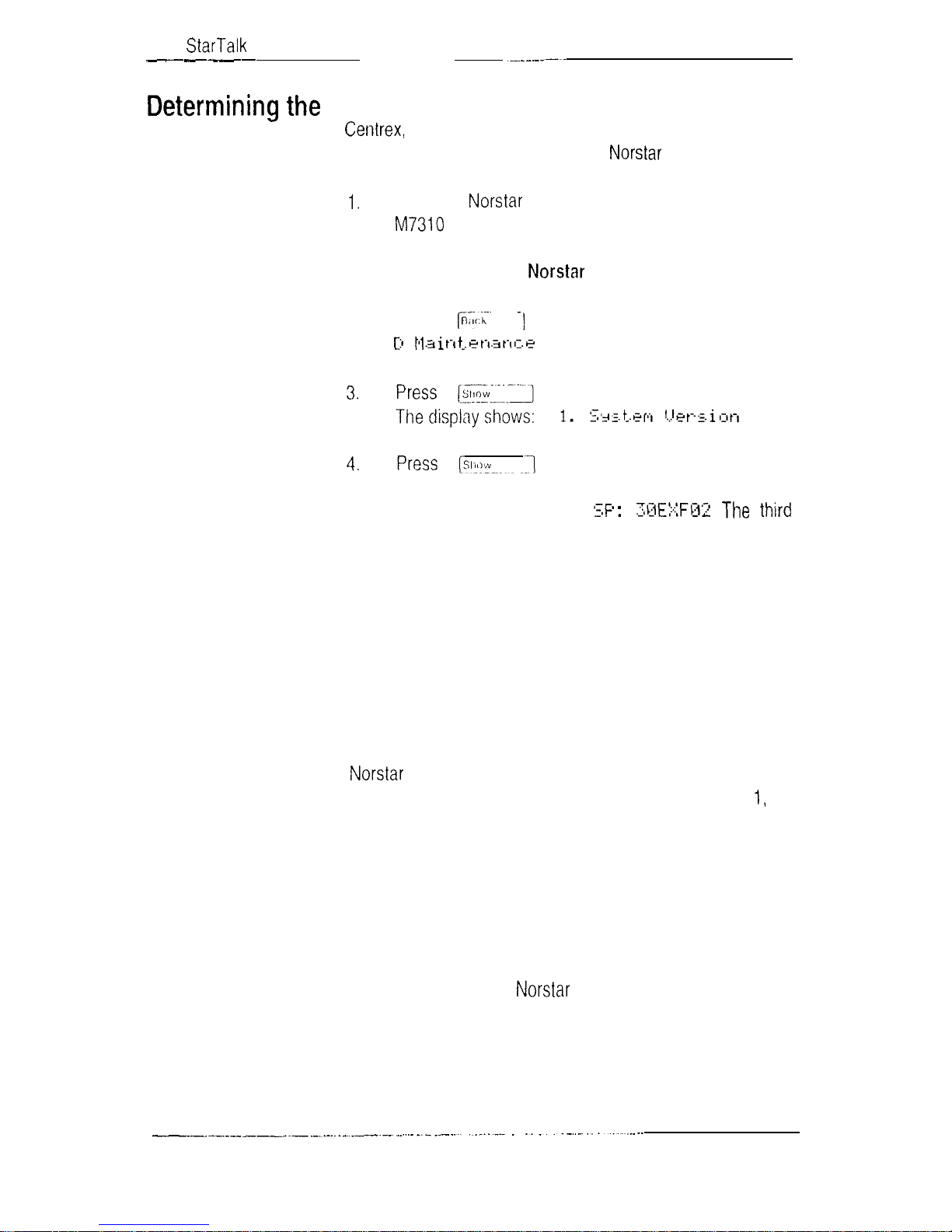
KSU software
The Modular KSU is available with DR2, DR3, DR4, DR5,
software and software version in the system:
type and
version
2.
For example: the display shows:
character to the right of the colon indicates the kind of KSU
software. The fourth character to the right of the colon
indicates the language combination of the KSU software.
The last three characters indicate the version of software
being used.
and Centrext software. To determine the kind of
Enter the Configuration programming from any
or M7324 telephone.
Note:
ming, refer to the
For more information on Configuration program-
KSU Installation Guide.
Press
.
to move to the Heading
If the fifth character to the right of the colon is not an E, the
KSU software is compatible. If the character is an E,
continue to verify the version number.
uses letters of the alphabet to designate version
numbers. The letter A represents 0, letter B represents
letter C represents 2, and so on.
In the example, F02 is the version number where F represents the number 5. Therefore, the KSU software version
number is 5.2.
Note:
If the software type is not DR2 version 5.2 or greater,
you must upgrade the software.
Page 30
Mini Installation Guide 25
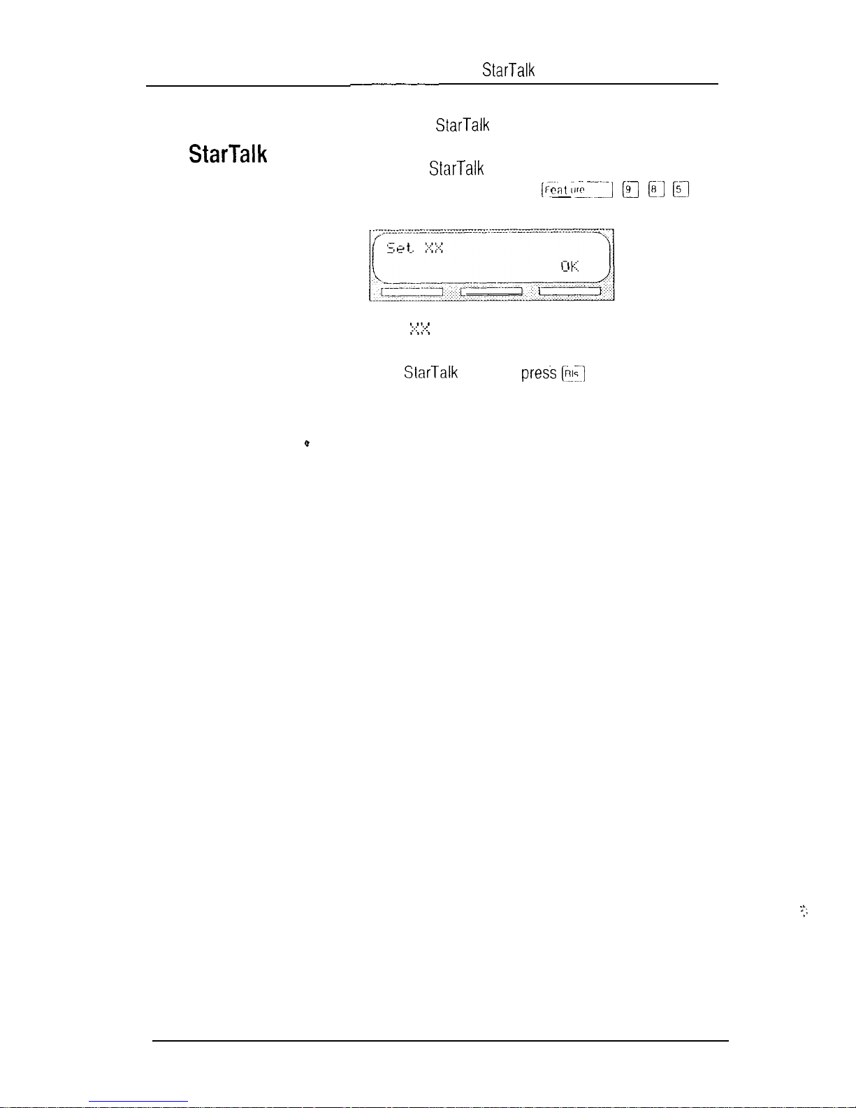
Determining TO
the k
software
version
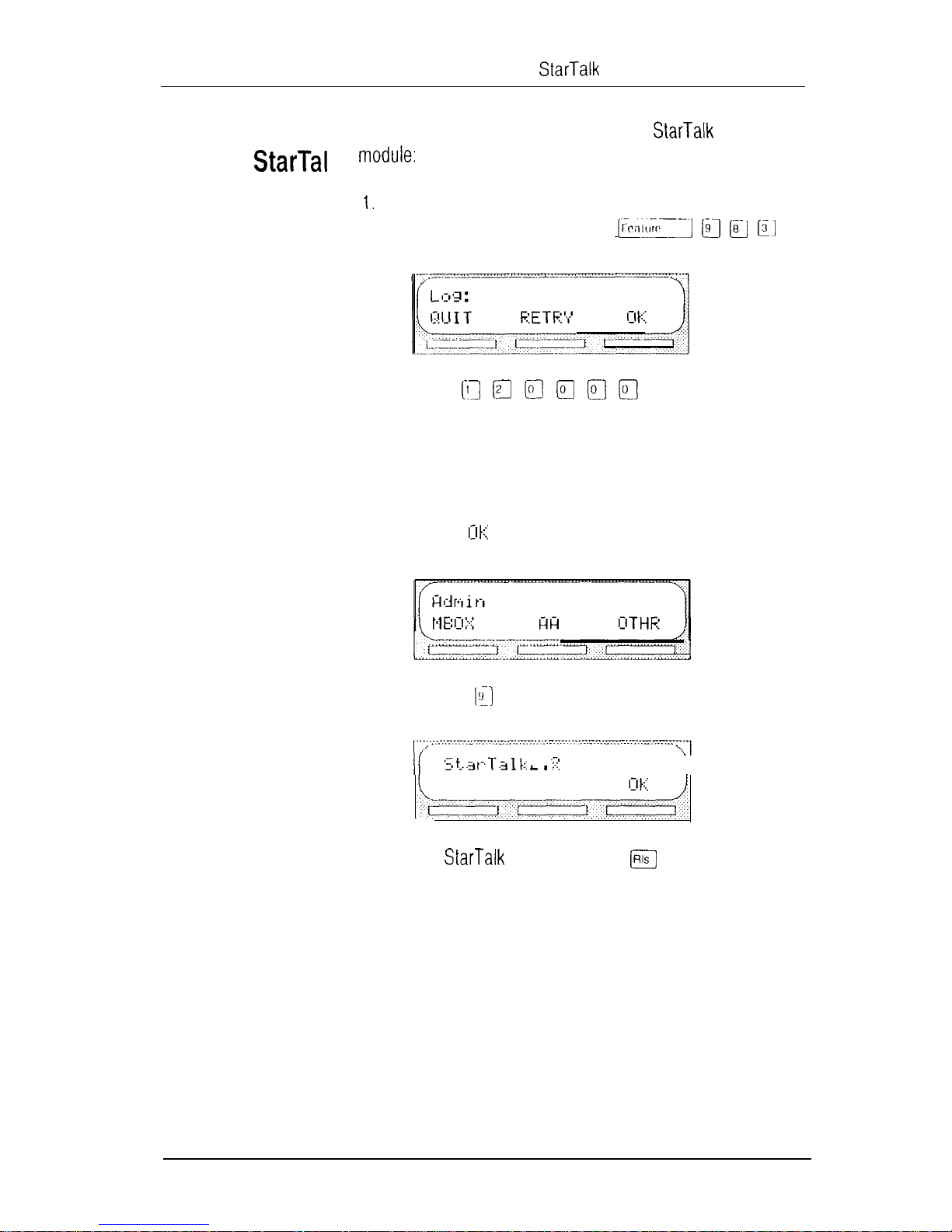
2.
3.
determine the software version of the Mini
Enter the System Administration Feature Code.
Note: The default code is
The display shows:
Enter
Note:
length being used. The mailbox number and default
password combination for each mailbox number length
are shown on
Press
The display shows:
This number depends on the mailbox number
Figures and Tables,
Table 3.
4.
To end the session, press
Press
The display shows:
\I
Page 31

26 Mini Installation Guide
Figures
and
The straight through cable is connected from the
Mini module to an terminal. 2 on one end is
connected to pin 2 on the other end, pin 3 on one end is
connected to pin 3 on the other end, and pin 7 on one end is
connected to pin 7 on the other end. The end of the cable
attached to
must be male.
Note: If the connector is not a 25 pin RS-232 connector,
refer to the operating manual of the terminal you are connecting for instructions.
Figure 4
Transmit Data
Receive Data
I
I Ground
Table 1
Mini Module
Pin Definition
Pin
Pin 2
Pin 3
Pin 7
RS-232 Terminal
Receive Data
Transmit Data
Ground
Page 32

Mini Installation Guide
27
Figure 5
Pin
1
2
3
4
5
Table 2
supply to
Attaching the RS-232 cable
Connection
no connection
GND
GND
Pin out of from the power
Mini
Figure
the power supply
Page 33

28 Mini Installation Guide
System Coordinator mailbox
and default password
DN length
mailbox
number length
combination
120000
1020000
10020000
100020000
1000020000
10000020000
Table 3 DN length, corresponding mailbox
number length and System Coordinator mailbox number and
default password combination
The default Feature Codes for are 980 through 986,
inclusive. When these Feature Codes are used by other
applications or products (i.e. PCI, RAD, SMDR)
assigns Feature Codes between 900 and 999 to
These codes might not be assigned in sequential
order. Record the assigned Feature Codes on Table 4.
Feature Code name
Number
Leave Message Feature 9 __ __
Open Mailbox
Feature 9 __ __
Operator Status Feature 9
System Administration Feature 9 __ __
Date and Time Feature 9 __ __
Directory Number Feature 9
Transfer
Table 4 Assigned Feature Codes
Feature 9 __ __
Page 34

_I_
-.
StarTalk Mini Reference Guide
-c
Page 35

Table of contents
How to use this guide
Introduction
How this guide is organized
Other documents
Knowing the different symbols
Prerequisites
l-l
l-2
l-3
1-4
2. Learning about
Introduction
How works
Who can use
About the Feature Codes
Determining
Feature Code descriptions
About the Automated Attendant
About the Company Directory
About the mailboxes
The Special Mailboxes
Personal Mailboxes
Information Mailboxes
Mailbox rules
Using the
Using with a two-line display
Using
Using
Entering characters into the command line
About the
Interrupting a voice prompt
Exiting from
Programming a memory button
with a single-line display
with an Analog Terminal Adapter
voice prompts
Feature Codes
2-1
2-l
2-l
2-2
2-3
2-4
2-5
2-6
2-7
2-a'
2-a
2-9
2-9
2-9
2-10
2-11
2-11
2-12
2-13
2-14
2-14
2-14
2-15
Mini Reference Guide
Page 36

2 Table of contents
3. Information Mailboxes
Introduction
Using Information Mailboxes
Where to begin
Recording the Information Mailbox Greeting
4. Your Personal Mailbox
Introduction
Personalizing your mailbox
Initializing your mailbox
Your personal greetings
Primary mailbox greetings
Alternate mailbox greetings
Recording your primary greeting
Recording your alternate greeting
Selecting a personal greeting
Mailbox options
Listening to your messages
Options while a message is playing
Options at the end of a message
Copy option
Reply options
Record a message
Mailbox Administration
Changing a Company Directory name
Greeting options
Record option
Selecting a greeting
Changing your mailbox password
Off-premise Message Notification
Setting Up Off-premise Message Notification parameters
Assigning Message Notification
Changing the destination number
.
3-l
3-l
3-l
3-2
3-3
4-l
4-l
4-l
4-2
4-5
4-6
4-6
4-7
4-9
4-11
4-13
4-14
4-14
4-16
4-17
4-18
4-19
4 20
4-22
4-22’
4 23
4-23
4-25
4-25
4 29
4 30
Mini Reference Guide
Page 37

Table of contents 3
5. The Leave Message feature
Introduction
Using the Leave Message feature
Assigning Message Delivery options
Using the Company Directory option
Selecting the Company Directory option
Leaving a message from a
Leave Message options
Opening your mailbox after leaving a message
Transferring a caller to a mailbox
The different types of
Group Message
About the Group List
Broadcast Messages
telephone
messages
6. Telephone etiquette
Introduction
Telephone etiquette
5-1
5-l
6-1
6-l
7. Troubleshooting
Introduction
Timeout
Messages are cut off
Mailbox full too often
Wrong prompt language
Glossary
Index
7-l
7-l
Glossary
Index 1
Mini Reference Guide
Page 38

4 Table of contents
Mini Reference Guide
Page 39

How to use this guide
l-l
Introduction
this guide
is organized
This guide is designed to assist you in using the Business Communication
describes the features accessible to a
This section tells you what to expect as you read through this guide, and how
information contained in this guide is presented.
The
How to use this guide
of this guide and the conventions used for describing features and their
operation.
Learning about
section defines the terms that are used in explaining the features.
Mini voice module. The information contained in this guide
user.
Mini Reference Guide
provides a brief overview, identifying the organization
provides an overview of how works. This
is organized according to sections that
. .
Information Mailboxes
and how to use them.
Your Personal Mailbox
up a Personal Mailbox, and also provides a description of all the options
accessible from a mailbox.
options that can be selected from the Leave Message feature.
Telephone etiquette
Troubleshooting
that might occur while operating
and are of Northern Telecom
Mini Reference Guide
provides a description of the Information Mailboxes
provides an outline of the steps you perform to set
Leave Message feature
provides a list of suggestions for operating
provides diagnostic and recovery procedures for problems
provides information about the different
Page 40

1
2 Section 1: How to use this guide
Other
documents
Glossary
Index
information is located. The Index is in alphabetical order. If you cannot find a
term, try looking for your item according to its task.
For more information about see your System Coordinator or refer to
the
defines the terms used in this guide.
provides a list of everything contained in this guide and where the
Mini User Card.
Mini Reference Guide
Page 41

Section 1: t-low to use this guide 1 3
Knowing
different
As you work through this guide, you will notice that conventions have been used
to represent the words that appear on the display.
Display command line text
Words in the first line of the display appear in a different text. Any word or
prompt that is part of the first line of the display appears in a different text.
Example:
When see a word in a different text, it represents the action you must take
to proceed.
Display button options text
Options in the second line of the display appear in an underlined text.
Example:
When you see an underlined word, you can press the button directly below the
option the display to proceed.
Buttons
This guide uses button representations. Any button that appears in the
text or instruction steps indicates the button that selects an option.
Example:
When you see a button, it represents the button you must press to
proceed.
Angled brackets
Some information is descriptive information that is entered using the
This descriptive information is always enclosed in angled brackets.
Example:
Press
Enter mailbox owner’s last name and first initial>
The information in angled brackets describes what you should enter. In the
example above, you would enter a user’s last name and first initial by pressing
the corresponding buttons on your telephone.
Mini Reference Guide
Page 42

1 4 Section 1: How to use this guide
Before you attempt to use ensure that you are familiar with how the
requisites
look through your telephone user card before proceeding.
one and two-line display telephones operate. We recommend that you
Mini Reference Guide
Page 43

Learning about
2-1
. .
Introduction
--
is a fully automated receptionist service that offers call routing and
message taking services. This section describes how works and
covers:
basic system operation
using the Feature Codes
the Automated Attendant
the Company Directory
the different mailboxes
using the
the displays
voice prompts
exiting from
entering characters into the command line
programming a Feature Code memory button
receptionist service that routes calls and provides voice message taking
capability. When enabled, answers incoming calls and routes the calls
works
Mini Guide
to extensions and mailboxes within the system.
.
.
The first component is the Automated Attendant. The Automated Attendant
works like a receptionist would when answering incoming calls. The Automated
Attendant plays a list of options to a caller with a voice prompt. If you know
which option you want, you can interrupt the Automated Attendant by pressing
your selection on the
works with a Business Communication System, offering a
has three main components:
Automated Attendant
Mailboxes (Voice Messaging)
Custom Call Routing (CCR)
of any tone dial telephone.
Page 44

2 2 Section 2: Learning about
When an option has been selected, the Automated Attendant responds to the
command by either routing the call to an extension or mailbox within your
company, or directing a caller to the Company Directory or designated operator.
The second component of
System Coordinator and then initialized by the mailbox owner. They store the
voice messages left by callers. Any caller can leave a message after a mailbox
is initialized.
Each mailbox owner can customize a Personal Mailbox with special
options. The mailbox options are:
record and select primary and alternate greetings
.
.
.
.
The third component of
single-digit access application, providing callers with a series of voice prompts
and call transfer options. Using CCR, a user can:
.
.
password selection
record a name in the Company Directory
set up and maintain Off-premise Message Notification
receive and send messages
listen to the Home Menu and make a selection
listen to a pre-recorded Information Message
leave a message in a mailbox
transfer to an extension
is mailboxes. Mailboxes are added by the
is Custom Call Routing (CCR). CCR is a
Who
can use
company. Away from the office, can be used with any tone dial
telephone. Inside your office, can be used from any telephone
or tone dial telephone connected to your company’s Business Communication System.
Even outside callers using a rotary dial telephone are able to use
When a caller uses from a rotary dial telephone, transfers the
caller to your company receptionist or designated operator. If a receptionist or
designated operator is not available
to General Delivery Mailbox.
can be used by any outside caller, and by mailbox owners in your
answer the call, the caller is transferred
Mini Reference Guide
Page 45

Section 2: Learning about
2
About the
Feature
Codes
When you are using from a telephone, you must enter a
Feature Code. Feature Codes are used to access the different functions and
options of
first be entered.
Feature Codes are assigned during the
Feature Codes for are 980 through 986, inclusive. When these
Feature Codes are used by other applications or products (i.e. PCI,
Hourglass,
These codes might not be assigned in sequential order. For more
information about Feature Codes, see your System Coordinator.
Table 2.1 shows the default Feature Codes, and also provides a space to
record the assigned Feature Codes.
To use a function or option, a Feature Code must
installation. The default
assigns Feature Codes between 900 and 999 to
Table 2.1 Feature Codes
Mini Reference Guide
Page 46

2 4 Section 2: Learning about
Determining
Feature
Codes
To determine the Feature Codes, you must use a or
M7324 display telephone. To determine Feature Codes:
2.
3.
4.
Press
The display shows:
Note:
Press The display shows the Feature Code for the Open
Mailbox feature. Record the Feature Code for the Open Mailbox feature
in Table 2.1.
Continue pressing to show all of the Feature Codes and
record these codes in Table 2.1.
represents a number between 00 and 99
the Feature Code for the Leave Message feature in Table 2.1.
q
When you reach the last Feature Code, the display shows:
To end this
session, press or T
Mini Reference Guide
Page 47

Section 2: Learning about
Feature
descriptions
Leave Message Feature Code
Is used by mailbox owners to leave a message in a mailbox initialized with
Users can also transfer a caller to a mailbox using the
Leave Message feature.
To use the Leave Message feature, press
Open Mailbox Feature Code
Is used by mailbox owners to open their Personal Mailboxes. All Personal
Mailboxes are protected by a password that is established by the mailbox
owner.
To use the Open Mailbox feature, press
Directory Number (DN) Feature Code
Is used to determine directory number. This number is used to
forward a telephone to and to use with an Analog
Terminal Adapter
To use the DN feature, press
Transfer Feature Code
Is used to transfer calls to a mailbox. While the call is active, enter the Transfer
Feature Code, then enter the mailbox number where you want to direct the call.
Do not put the call on hold. The caller is now transferred.
To use the Transfer feature, press
Feature Codes can be programmed for single button access.
information on programming Feature Codes, refer to
memory button,
Note:
The Feature Codes shown here represent the default Feature
Codes.
later in this section.
Programming a
Mini Reference Guide
Page 48

2 6 Section 2: Learning about
the
Automated
Attendant
The Automated Attendant is‘the receptionist. When enabled, the
Automated Attendant answers your company’s incoming telephone lines
according to the lime of day. When the Automated Attendant is turned ON, the
utomated Attendant menu prompt provides a list of options so that a caller
can:
reach an extension or a mailbox in your company
l
.
.
.
.
The Automated Attendant provides callers with commands to use each of
these options. A caller must press the button associated with the option they
want to activate. For example, to use the Company Directory, press
leave a message in a mailbox
select an alternate language (not a voice prompt)
look for an extension or mailbox in the Company Directory
reach your company receptionist or designated operator
open a Personal Mailbox as a mailbox owner (not a voice prompt)
When the default Automated Attendant menu prompt is turned OFF, the
System Coordinator must record a Customized Automated Attendant menu
prompt. This customized prompt should provide callers with a list of options,
such as leaving a message in a mailbox or reaching an operator. The customized prompt plays after the Company Greeting, and after a caller has recorded
and sent a message to a mailbox.
Mini Reference Guide
Page 49

Section 2: Learning about 2
About the
Company
Directory
The Company Directory is a list of mailbox owners registered with
Before any mailboxes can be used, the owners must record their names in the
Company Directory. If mailbox owners do not want their names to appear in the
Company Directory, they can see the System Coordinator. The Company
Directory can be changed at any time.
Any two-line display user can access the Company Directory
by selecting I when the display shows the Directory option. The Company
Directory can also be opened by pressing when the Automated Attendant
announces the option is available.
When you have opened the Company Directory, you can enter the last name of
a mailbox owner or you can press
the members of the Company Directory, the
the first member in the Directory. To see the next name, you must press
to view all the names. When you view
display shows the name of
Mini Reference Guide
Page 50

2 8 Section 2: Learning about
About the
mailboxes
The Special
A mailbox is a storage place for messages. The Mini system can store
24 mailboxes. There are three groups of mailboxes including:
.
.
l
Special Mailboxes
Personal Mailboxes
information Mailboxes
The Special Mailboxes are administered by your company’s System
tor. The Special Mailboxes include:
System Coordinator Mailbox
.
System Coordinator Mailbox
General Delivery Mailbox
This mailbox is used by your System Coordinator as a Personal Mailbox. You
can leave’messages for your company’s System Coordinator in this mailbox.
The System Coordinator Mailbox has a default mailbox number of 12. This is
the number assigned when the mailbox number length is set at two. Mailbox
number lengths range from two to seven digits. For more information about the
System Coordinator Mailbox numbers, see your System Coordinator.
General Delivery Mailbox
This mailbox is used to collect messages from callers who use a rotary dial
telephone, for individuals in your company who do not have Personal Mailboxes,
and for mailbox owners whose mailboxes are full. Your company’s receptionist
or System Coordinator will route messages left in the General Delivery Mailbox
using
COPY option.
The General Delivery Mailbox has a default mailbox number of 10. This is the
number assigned when the mailbox number length is set at two. Mailbox
number length ranges from two to seven digits. For more information about the
General Delivery Mailbox numbers, see your System Coordinator.
For more information about the Special Mailboxes, see your System Coordinator.
Important:
number length is 2, the Special Mailbox numbers default to 20 and 22.
If the Group List leading digit is assigned as 1 and the mailbox
Mini Reference Guide
Page 51

Section 2: Learning about
2 9
Personal
Mailboxes
Personal Mailboxes are assigned by your System Coordinator and maintained
by the mailbox owner. A Personal Mailbox can be a User or Guest Mailbox,
For more information about your Personal Mailbox features and options, refer to
Section 4: Your Personal Mailbox.
User Mailboxes
User Mailboxes can be assigned to each user who has an operating
extension. User Mailboxes store the messages for users who are unable to
answer their telephone.
Guest Mailboxes
Guest Mailboxes provide temporary employees and guests with access to
internal messaging and call routing features. Guest Mailboxes do not have an
operating extension. To request an Guest Mailbox, see your System
Coordinator.
Information Mailboxes provide greetings that relay important company or
department messages. information Mailboxes do not have an operating
extension, To request an Information Mailbox, see your System Coordinator.
Mail box
Only a few rules apply to the mailboxes. Remembering these rules
make using your mailbox a simple, everyday task.
The mailbox rules are:
1.
You must always enter a password.
2.
3.
A mailbox can be opened from any telephone from the
display prompt by entering the mailbox number and password
combination.
When a mailbox is assigned to a
shows the
or
When a single line display is being used, press
to reach the display prompt.
A mailbox must be initialized before it can be used.
prompt. To reach the prompt, press
telephone, the display always
q
Mini Reference Guide
Page 52

2 10 Section 2: Learning about
the
The buttons on the act as both numbers and letters. Each button
represents a number and also represents letters of the alphabet.
The is shown in Figure 2.1.
Figure 2.1
When you are entering a name using the Company Directory option, you need
only press the number button associated with the letters of the name once, You
do not need to enter a comma. For example, if you are looking for the last
name Taylor, you would press:
When you are looking for a mailbox owner using the Company Directory, you
can find the name by entering the first four letters of the last name. If
cannot find the name the first time, you can press or
the names in the Directory, press
find the mailbox owner you are looking for.
Note: If you are trying to find a mailbox owner with less than four letters in the
last name, for example Fry, press the buttons on the
last name, and press
q
To view all
Then press or until you
that spell the entire
Mini Reference Guide
Page 53

Section 2: Learning about 2
Using
with a
two-line
display
The two-line display on and M7324 telephones provides
information about options and commands available when you are using
The display can provide up to three display button options at a time. In some
instances, you must wait for the voice prompt to play the other available
options. In those instances when options are played by the voice prompt and
the corresponding button does not appear on the display, you must select the
option using the numbers on the
The two-line display is shown in Figure 2.2.
Display
--
command line
button options
Using
with a
single-line
display
--
2.2 two-line display
The
used for any session. If you are using a telephone with a
single-line display, the display shows only the
All options are given immediately by the
options are selected using the
option list, you can interrupt the voice prompt and make your selection immediately.
buttons
and M7208 telephones with a single-line display can be
command.
voice prompts and your
only. When you become familiar with
options, you do not need to wait for the voice prompt to complete the
Mini Reference Guide
Page 54

2 12 Section 2: Learning about
A single-tine, tone dial connected to a KSU through an
Analog Terminal Adapter can be used for any session. How-
ever, you cannot use a single-line telephone attached to an
System Administration tasks.
Analog
There is no Message Waiting Notification capability when you are using an
Terminal
Adapter
Although the single-line telephone does not have a feature button, you can
access
To access features, such as Leave Message or Open Mailbox, call
and follow the voice prompts. The DN determined by using
Feature 985 on a telephone.
If you have an Enhanced you can also enter:
features.
for
to open your mailbox,
or
and
follow the voice prompts.
Note:
When a caller uses from a rotary dial telephone,
transfers the caller to your receptionist or designated operator, If a
receptionist or designated
is transferred to General Delivery Mailbox.
is not available to answer the call, the caller
Mini Reference Guide
Page 55

Section 2: Learning about
2
Entering
characters
line
The command line of the display shows 16 characters at a time. There
are several situations when the prompt and the information to be entered
combined total less than 16 characters, and you can see both the command
and the information you entered. The prompt remains on the display when less
than ten characters are entered. The maximum number of characters you can
enter is 16.
For example:
There are four situations when the command line prompt will disappear. This
happens when the display shows the command line prompt:
For instance, when the display shows:
Once you begin to enter the last name, the command line prompt disappears.
For example, if you were entering the name S. Martin, you press the
button for M, the display drops the
After you have entered the entire name, the display shows:
The display does not show the command line prompt:
and changes to show:
,
Mini Reference Guide
Page 56

14
Section 2: Learning about
the
Each command that is shown on the
rom On a two-line display telephone, the voice prompt plays after a
five second delay. When you do not select an option, will exit. On a
single-line display telephone, the voice prompt plays immediately.
When you do not select an option within the next five seconds, the voice
prompt replays the options before ends the session.
voice prompts provide the same options as the display button options,
and additional options not appearing on the display. When the voice prompt
plays the available options, it only provides the
invoke the options.,
When the voice prompt announces a display option with a corresponding
button, you can use the display buttons or buttons. Either
button will invoke the selected option.
When
the language of the Automated Attendant prompts for the duration of the call.
The user can press
mated Attendant voice prompt or before recording a message using the Leave
Message Feature.
has bilingual language capability enabled, a user can change
on the while listening to the top level Auto-
display is accompanied by a voice
number buttons that
Interrupting
a voice
prompt
Exiting
from
Voice prompts can be interrupted by selecting an option on the display or
A voice prompt can also be stopped by pressing
interrupt a prompt that is informing you of an error.
When a single or two-line display telephone is being used, pressing
backs up the display to the-previous display prompt.
YOU
can exit from
Replacing the handset.
You cannot
2.
3.
Note: When you press
three seconds, except when you are transferring a caller to a mailbox.
Pressing an alternate line button.
Pressing
- the session will end in two to
Mini Reference Guide
Page 57

ming a
memory
Section 2: Learning about 2 15
enables you to program each Feature Code to a single
memory button. When programmed, the Feature Codes are easily
accessed using a single button on your
The most frequently used Feature Codes are:
telephone.
Leave Message
.
.
.
To program a memory button:
2.
Open Mailbox
Determine
Directory Number
Transfer
The display shows:
Note: What appears on the display is determined by the
software version installed on your Mini system. Regardless of
the version in use, follow the same steps to program a memory button.
Select a programmable button.
Feature 980
Feature 981
Feature 985
Feature 986
4.
5.
Repeat steps 1 through 5 for each Feature Code you want to program.
Mini Reference Guide
Enter the Feature Code number. For example, 980.
The display shows:
Label the button with the Feature Code description, using the paper
labels provided with your telephone.
Page 58

2 16 Section 2: Learning about
Mini Reference Guide
Page 59

3-l
Information Mailboxes
This section describes the Information Mailboxes, how to use them, and the
tasks you need to perform to maintain them.
Information Mailboxes are set up by the System Coordinator and maintained by
the user. The Automated Attendant voice prompt provides a caller with single
digit options to access Information Mailboxes.
Note: Information Mailboxes are different from CCR Information Mailboxes.
CCR Information Mailboxes are set up and maintained by the System Coordinator. Callers must use the CCR Tree to access a CCR Information Mailbox. For
more information about Information Mailboxes, see your System Coordinator.
Information Mailboxes provide messages and announcements to callers,
Mailboxes .
Information Mailboxes can be used to:
announce sales
.
.
For example:
Room. dance is
Contemporary jazz in the Blue Room. The Studio and Recital Rooms are
located at 222 Street, Anywhere. S. A.
provide product lists
announce special events
“On Your Toes Studio an extravaganza of dance. The
at on Toddlers lap is in the White
the Green Room. Classical is in the Pink Room.
Mini Reference Guide
Page 60

3 2
Section 3: Information Mailboxes
When you use the Information Mailbox feature, you must ensure the mailboxes
are accessible to callers.
Important:
You must make the Information Mailboxes easy for a caller to find.
You can do this using your company’s operator or the Company
Greetings. For details, see your System Coordinator.
If you are using a
Mini system with bilingual capability, the Information
Mailbox greeting must be recorded in both languages.
Before you record your Information Mailbox Greeting, you must determine what
the greeting is to include. When preparing your greeting, be sure to include
important times and dates. Write the greeting out and practice reading it aloud.
When you’are confident the greeting includes everything you want it to, record
the greeting.
Mini Reference Guide
Page 61

Section 3: information Mailboxes
Recording
the
information
Mailbox
Greeting
The Mailbox Greeting can be recorded or changed whenever you
need to update the recording.
To record your Information Mailbox Greeting:
1.
2.
3.
Press
The display shows:
Press
The display shows:
Enter <the information Mailbox number and password>
Note:
For your Information Mailbox number and password combination,
see your System Coordinator.
4.
5.
Press or
The display shows:
Press
At the tone, record the prirnary Information Mailbox Greeting.
Note:
For information about Pause and Continue while recording a
greeting refer to
telephone.
Section 5, Leaving a message from a
Reference Guide
Page 62

3 4 Section 3: Information Mailboxes
6.
Press to end the recording.
The display shows:
Note: To listen to your greeting before accepting it, press
record your greeting again, press
7.
Press to accept the recording.
Note: To record an alternate lnforrnation Mailbox Greeting, press
and follow the instructions that appear on the display.
To end this
..&-
t-
session, press
To
Mini Reference Guide
Page 63

Your Personal
is a fully automated receptionist service that offers call routing and
message taking services. This section describes how
covers:
personalizing your mailbox
initializing your mailbox
recording your primary and alternate greetings
selecting a mailbox greeting
mailbox options
listening to messages
recording a message
mailbox administration
changing a Company Directory name
greeting options
changing your mailbox password
Off-premise Message Notification
disabling Off-premise Message Notification
changing the destination number
works and
. .
Personalizing your mailbox involves initializing your mailbox to receive
ing your
sages, recording and selecting greetings that will make your mailbox uniquely
yours. Personalizing your mailbox consists of:
mailbox
.
.
.
.
Mini Reference Guide
initializing your mailbox
recording your primary greeting
recording your alternate greeting
choosing which greeting you want to play
Page 64

4 2 Section 4: Your Personal Mailbox
Initializing a mailbox prepares the mailbox to receive messages. A mailbox
your
mailbox
cannot receive and store messages until it has been initialized. Initializing a
mailbox involves:
changing the default password
When your company’s System Coordinator registers a mailbox, it is
given a
default password. For all new mailboxes, this pass-
word is 0000 (four zeros).
recording your name in the Company Directory
This establishes your “voice” name in a directory that is used by other
users and outside callers who search through the Company
Directory.
Note: If you do not want your name to appear in the Company Directory, see your System Coordinator.
To initialize your Personal Mailbox:
2.
3.
display
shows:
Note: If you are using a telephone that has not been assigned
to you, you must press to access the display prompt.
From the
display prompt, enter your mailbox number and the
default password.
Enter <the default password
The display shows:
--
--- . .
Mini Reference Guide
Page 65

Section 4: Your Personal Mailbox 4
4.
5.
6.
7.
Enter <your Personal Mailbox password>
Note: Your password must be between four and eight digits long. A
password cannot start with zero (0).
To end your password, press or
The display shows:
To accept your password, press or
The display shows:
At the tone, record your name.
Note: When you record your name, remember to speak clearly and at a
pace that is easy to understand. It is a good idea to include your
mailbox number in your Company Directory recording. For example,
“Marina
mailbox number 41
To end your recording, press or
The display shows:
Note: To replay your before accepting it, press
or
To re-record your recording, press or
Mini Reference Guide
Page 66

4 4 Section 4: Your Personal Mailbox
9.
To accept your recording, press or
The display shows:
After your mailbox is initialized, you must record your Personal Mailbox
Greeting. Refer
your alternate greeting,
to Recording your primary greeting
and
Recording
later in this section.
Your mailbox is now ready to receive messages. You can change both your
password and your Company Directory name at any time. To change your
password refer to
To change your Company Directory recording refer to
Directory name,
Changing your mailbox password,
later in this section.
Changing a Company
later in this section.
Mini Reference Guide
Page 67

Section 4: Your Personal Mailbox 4
Your personal
greetings
Personal greetings are played to callers who choose to leave a message in your
mailbox. There are two types of personal greetings: the primary and alternate
greetings.
The purpose of both greetings is to inform callers they have reached the correct
mailbox-yours-and to give callers any necessary information or instructions,
You can change primary and alternate greetings at any time.
Note: If you do not record any personal greetings, your Company Directory
name recording plays to callers who reach your mailbox.
When you record your primary and alternate greetings, you should include your
name, extension, and a brief explanation that you are to answer the call
personally. You can include in your alternate mailbox greeting how long you
plan to be away from your desk or office, and whether or not you are away on a
business trip, vacation, or sick leave. You should also assure callers their
messages will receive your prompt attention.
When recording your personal greetings, remember to speak clearly, with a
pleasant voice, at a pace that is easy to understand. Do not speak too softly or
too loudly, or make your greeting too lengthy. After recording a greeting, you
should replay the greeting before accepting it to ensure the recording sounds
the way you intended.
You can record or change a greeting from any telephone or, if you are
away from the office, from any tone dial telephone.
Note: Whenever you are recording a greeting, do not use Norstar’s Handsfree
feature. A better recording
speak directly into the handset.
Mini Guide
Page 68

4 6 Section 4: Your Personal Mailbox
Primary
mailbox
greetings
Your primary mailbox greeting is recorded for everyday use. This greeting
should include your name and a brief message explaining to callers that you are
unable to answer their call. Recording your greeting with a friendly voice, and
the details of when you will be back at your desk to take calls, encourages
callers to leave you a message. For example:
If you are a new mailbox owner, you should record your primary greeting
immediately.
Alternate
mailbox
In special circumstances, such as business trips, vacation, or sick leave, you
wilt want to leave callers special information. For this reason, provides
greetings you
greeting. For example:
“Hi.
This is Paul Wayne. I’m not able fake your fight now.
Please leave me a message at the tone and I will return your call as
soon as possible.
with an alternate greeting. This greeting is called the alternate mailbox
“/ii. This is Paul Wayne.
December 17. Although
daily.
call
Please leave me a message at the tone and I will your
as soon as possible. Thank you.
am of office until Thursday,
am out of the office, I do check my mailbox
Because the alternate greeting is normally used for special circumstances, you
do not have to record one until the need arises. You can select which greeting
you want
to play. You can change the selection at any time, and as
often as needed.
Note:
After you have recorded your greetings, you must choose the greeting to
be played. If you do not choose a greeting, the primary greeting plays automatically. Whenever you choose the alternate greeting, remember to change back
to the primary greeting when your circumstances return to normal.
Mini Reference Guide
Page 69

Section 4: Your Personal Mailbox
4
7
Recording
your
primary
greeting
To record your primary greeting:
2.
3.
Press
The display shows:
Enter <your password>
Note: Your unique password was determined when you first opened
your mailbox and performed the initialization steps. If you are recording
a greeting from a
assigned to your Personal Mailbox, press
prompt. When this prompt appears, enter your mailbox number
and password combination.
Press OK or
The display shows:
telephone extension that has not been
The display shows the
4.
5.
6.
Press
The display shows:
Press
The display shows:
Press
The display shows:
GREET
or
or
or
Mini Reference Guide
Page 70

4 8 Section 4: Your Personal Mailbox
7.
8.
9.
10.
Press
Note:
If you are changing your primary greeting, your current
or
recorded primary greeting begins to play.
The display shows:
Press
or [I
The display shows:
At the tone, record your greeting.
Press or to end your recording.
The display shows:
11.
You now have the options to RETRY (re-record) the greeting, PLAY the
greeting back, or OK (accept) the greeting. When you are satisfied with
the
greeting, press or to return to
the
prompt.
Your primary personal greeting is now recorded.
After you have recorded your primary and alternate greetings, you must choose
the greeting to be played. If you do not choose a greeting, the primary greeting
automatically plays. Refer to
Selecting a personal greeting,
later in this
section.
Mini Reference Guide
Page 71

Section 4: Your Personal Mailbox
4
9
Recording
your
alternate
greeting
To record your alternate greeting:
2.
Press
The display shows:
Enter <your password>
Note: Your unique password was determined when you first opened
your mailbox and performed the initialization steps. If you are recording
a greeting from a
assigned to your Personal Mailbox, press
prompt. When this prompt appears, enter your mailbox number
and password combination.
The display shows:
telephone extension that has not been
The display shows the
4.
5.
Press or
The display shows:
Press
or
q
Mini Reference Guide
Page 72

4 10 Section 4: Your Personal Mailbox
6.
7.
8.
Press or
The display shows:
Press or
q
Note: If you are changing your alternate greeting, your current recorded
alternate greeting begins to play.
The display shows:
Press
The display shows:
or
9.
10.
At the tone, record your greeting.
Press or to end your recording.
The display shows:
11.
.
After recording your greeting, you can RETRY (re-record) the greeting,
PLAY the greeting back, or OK (accept) the greeting. When you are
satisfied with the greeting, press
Ha
i 1
i prompt.
or to return to the
You have now finished recording your alternate mailbox greeting. For instructions about selecting your alternate greeting, refer to
greeting,
later in this section.
Selecting a personal
Mini Reference Guide
Page 73

Section 4: Your Personal Mailbox 4 11
Selecting a
personal
greeting
For a primary or alternate greeting to play, you must select a greeting. If you
do not select a greeting, the primary greeting plays automatically. If you select
the alternate greeting, remember to change back to the primary greeting at the
appropriate time.
To select a primary or alternate greeting:
2.
The display shows:
Enter <your password>
Note: Your unique password was determined when you first opened
your mailbox and performed the initialization steps. If you are recording
a greeting from a
assigned to your Personal Mailbox, press
the
prompt. When this prompt appears, enter your mailbox
telephone extension that has not been
The display shows
number and password combination.
3.
4.
5.
Press or
Press I or
The display shows:
Press
or
The display shows:
Mini Reference Guide
Page 74

4 12 Section 4: Your Personal Mailbox
The display shows:
x,.-w --
--
I-----.-.---
7.
Your Personal Mailbox Greeting is now selected and plays each time a caller
chooses to leave a message in your mailbox. If you choose the alternate
greeting, remember to change back to the primary greeting at the appropriate
time.
Select the greeting you want to play.
To select the primary greeting, press or
To select the alternate greeting, press RLT or
The display changes to show:
Note: If you have selected a greeting that is not yet recorded, you are
transferred back to the Greeting options to record the greeting.
q
and then
Mini Reference Guide
Page 75

----
Section 4: Your Personal Mailbox 4 13
---
Mail box
options
Open Mailbox Feature is powerful, easy to use, and designed to
increase office productivity. Following is a description of all the options you can
use with this feature. To open your mailbox:
1.
If you are calling from an outside telephone, press
mailbox. At the prompt, enter your mailbox number and password. If you are
calling from a
the
mailbox number and password combination.
Once in your mailbox, you can choose from six options. These options are
referred to as the main mailbox menu.
Press
prompt, press The display shows: Enter your
El
Listening to your messages
begin playing the messages in your mailbox. When someone sends you
a message, your
After opening your mailbox, automatically plays Broadcast
Messages. The display informs you of the number of messages
in your mailbox. Urgent messages are played next. Then, new mes-
sages are played in the order received from first message (oldest) to last
(most recent). Saved messages are played last.
telephone other than your own, when the display shows
and enter your password.
to open your
Selecting the Play option tells to
telephone display shows
El
El
Listening to your saved messages
saved messages in your mailbox.
Recording a message
to one or more mailboxes.
Mailbox Administration
record your name in the Company Directory, record and select primary
and alternate personal greetings, change your password, and establish
Off-premise Message Notification.
Operator
operator, if one is available. This option does not appear on your
display.
To Use the Automated Attendant
Automated Attendant. This option does not appear on your display,
This option transfers you from your mailbox to an internal
Use this option to record a message and send it
With Mailbox Administration options you can
Use this option to listen to the
This option transfers you to the
Mini Reference Guide
Page 76

4 14 Section 4: Your Personal Mailbox
Listening
One set of options is available while a message is playing, and another set is
messages
Options
while a
message is
playing
After you select the Play option, your messages will begin playing automatically.
available after a message has played through to the end.
While you are listening to a message, you can:
Replay
plays it again. Press on the display,
Backup
This option rewinds the message to the beginning and
This option backs up (rewinds) the message nine
seconds and resumes playing the message from that point.
Press on the display.
Pause/Continue
This option temporarily stops a message that
is playing. When you stop the message, you have the option to
play the previous message, continue playing the current
message, or skip to the next message. You can stop and
continue a message as many times as required.
End of Message
This option allows you to skip all the way to
the end of the message being played. To reach the end of the
Forward
This option advances the message nine seconds and
continues playing from that point. Press
display.
on the display A
message can be forwarded as many times as required.
Previous
This option stops playing the current message and
begins playing the previous one. This option is not shown on the
display.
Copy
This option allows you to send a copy of the message to
one or more mailboxes. When you record an introduction to a
message, the introduction must be more than three seconds
long. This option is not shown on the’display.
Mini Reference Guide
Page 77

Section 4: Your Personal Mailbox 4 15
Next
This option stops playing the current message and begins
playing the next message in your mailbox. This option is not
shown on the display. You can also press
to listen to the
next message.
Envelope
This option plays the information on the message’s
envelope. The envelope information is similar to that on a letter
sent through the postal service. It includes the date and time the
message was sent and, if the message was internal, the
directory name of the sender. This option is not shown on the
display.
Save Message
This option saves the message being played.
This option is not shown on the display.
Erase
This option deletes the message being played. If you do
not delete a message, it is automatically saved. Since your
mailbox has limited message storage space, you should delete
any messages you no longer need.
Reply
This option allows you to reply to the message. Your
reply to the sender can be either a message to the sender’s
mailbox, or a telephone call. automatically sends your
message to the sender’s mailbox or dials the sender’s extension.
This option is not shown on the display and is not available for
messages left by outside callers.
Note:
After listening to the messages left in your mailbox, and exiting
all messages you do not erase are automatically saved.
To end the session, replace the handset or press
Mini Reference Guide
Volume Control
that is playing. Pressing
This option adjusts the volume of the message
increases the volume by 3
The volume can be increased to’a maximum of 9 When the
volume reaches 9
the next time you press the volume
returns to 3 This option is not shown on the display.
Page 78

4 16 Section 4: Your Personal Mailbox
Options at the
end of
a message
After a mailbox message has played, you can:
Replay
This option rewinds the message to the beginning and
plays it again. This option is not shown on the display.
Previous
This option plays the previous message. This option
is not shown on the display.
Copy
This option allows you to send a copy of the message to
one or more mailboxes. When you record an introduction to a
message, the introduction must be more than three seconds
long. This option is not shown on the display when the message
is from an inside caller.
Next
This option plays the next message in your mailbox.
Envelope
This option plays the information on the message’s
envelope. The envelope information is similar to that on a letter
sent through the postal service. It includes the date and time the
message was sent and, if the message was internal, the
directory name of the sender. The option is not shown on the
display.
Save Message
This option saves the message being played.
This option is not shown on the display.
Erase
This option deletes the message that just played. If you
do not delete a message, it stays in your mailbox indefinitely.
Since your mailbox has limited message storage capacity, you
should delete messages you no longer need.
Reply
This option allows you to reply to the message that just
played. Your reply to the sender can be either a message to the
sender’s mailbox, or a telephone call.
automatically
sends your message to the sender’s mailbox or dials the
sender’s extension. This option is not available for messages
left by outside callers.
Next Message
This option plays the next message in your
mailbox. This option does not appear on the display.
Quit
This option stops playing the message and replays the
Mailbox Main menu options.
Mini Reference Guide
Page 79

Section 4: Your Personal Mailbox 4 17
Copy option
When you select the option to forward a copy of a message to a mailbox, you
are first asked if you want to record an introduction to the message. When the
message is listened to at the other end, your introduction is played first,
followed immediately by the message.
You should record an introduction to a copied message. The message
introduction you must be at least three seconds long. You cannot
forward a message with an introduction that is
three seconds.
When recording an introduction, you use options to indicate you have finished
recording, or to erase what you have recorded so far and start over, After you
finish recording the introduction, you have options to erase and re-record, play,
or accept the introduction and send it, with the message, to a mailbox.
When you select SEND, you can choose a Delivery option to mark a message
CERTIFIED, URGENT, or PRIVATE. You can also enter the mailbox number of
the person you want to send the copy to. If you do not know the mailbox
number, you can find the mailbox owner in the Company Directory. If you
change your mind about forwarding the message, you can select the QUIT
option. This returns you to the end of messages options.
When you enter the mailbox number, your introduction and a copy of the
message are automatically sent to the mailbox you selected. You then have
options to send an additional copy of the introduction and the message to
another mailbox, or to quit and return to the Listen to Messages menu. You can
forward copies to as many mailboxes as you want.
Note: Messages marked PRIVATE cannot be forwarded to another mailbox.
l
Mini Reference Guide
Page 80

4 18 Section 4: Your Personal Mailbox
Reply options
You can reply to any message sent by a user who has a mailbox.
When you select the REPLY option, you must first indicate how you want to
reply to the message. You can reply by calling the message sender, or by
sending a message of your own to the message sender’s mailbox. If you
change your mind, you can quit and return to the end of messages options.
When you select the CALL option, dials the message sender’s
extension for you.
When you select the MSG option, you begin recording your reply at the tone.
While, recording the message, you can:
Retry
This option erases what you have recorded so far and
starts the recording session again. This option is not available
on a
Pause/Continue
single-line display telephone.
Selecting PAUSE temporarily stops the
recording session. When you are ready to continue recording,
select CONTINUE. You can pause and continue as many as
five times, If you are using a
single-line display tel-
ephone, press
OK
This option ends the recording session.
When you have finished recording your reply, you can:
Play
This option plays your recorded reply. As it is playing, you
can select options to retry the recording, play it again, or send it.
Retry
This option erases your recorded reply and starts the
recording session again.
Accept
When you select this option, accepts your reply
message.
Delivery options
This option allows you to mark your messages CERTIFIED, URGENT, or PRIVATE before sending them.
For more information about Delivery options, refer to
Section
Assigning Message Delivery options.
Send
When you select this option, automatically
delivers your reply to the message sender’s mailbox.
Mini Reference Guide
Page 81

a
message
Section 4: Your Personal Mailbox 4 19
When you open your mailbox, the Record a Message option is available on the
Mailbox Main menu. When you select this option, record your message at the
tone. While recording, you have three options:
Retry
starts the recording session again. This option is not available
on a single-line display telephone.
Pause/Continue
recording session. When you are ready to continue recording,
select CONTINUE. You can pause and continue as many as
five times. On a
press
OK
ing your message.
When you have finished recording your message, you can:
Play
you can select options to retry the recording, play it again, or
send it.
This option erases what you have recorded so far and
Selecting PAUSE temporarily stops the
single-line display telephone, you can
to
Pause
Select this option to tell you have finished record-
This option plays your recorded message. As it is playing,
and to
Continue.
Retry
recording session again.
Accept
mailbox number of the person(s) you want to send the message
to or use the Company Directory option.
Delivery options
sages CERTIFIED, URGENT, or PRIVATE before sending them.
Send
delivers your message to a mailbox.
Quit
Main menu options.
After you have sent your message, you can send a copy of the message to
another mailbox, or you can quit and select another option from the Mailbox
Main menu. If you choose to send a copy of the message you recorded to
another mailbox, you are asked to enter the mailbox number, as before.
This option erases your recorded message and starts the
This option accepts your message. You must enter the
This option allows you to mark your mes-
When you select this option, automatically
This option erases the message and replays the Mailbox
Mini Reference Guide
Page 82

4 20 Section 4: Your Personal Mailbox
Mail box
tion
Changing a
Directory
There are four Mailbox Administration options:
Directory name
the Company Directory. The option does not appear on your display.
Greetings
greetings, and to choose which greeting you want played.
Password
Off-premise Message Notification
notify you at another extension, a remote telephone number or
pager when a message is left in your mailbox.
This option allows you to change your name in the Company Directory, To use
this option, you must open your mailbox using Open Mailbox
This option is used to record or re-record your name in
This option is used to record your primary and alternate
This option allows you to change your mailbox password.
This option allows to
To record your Company Directory name:
2.
3.
4.
Enter <your mailbox password>
Press or
The display shows:
Press or
The display shows:
Mini Reference Guide
Page 83

Section 4: Your Personal Mailbox 4
21
5.
6.
7.
a.
While recording your Company Directory name, you can:
Press
Note:
This is a voice prompt option. It does not appear on the option
line of a two-line display telephone.
At the tone, record your name.
Note:
It is a good idea to include your mailbox (extension) number in
your recording.
To end your recording, press or
To accept your recording, press or
Retry
This option erases what you have recorded so far and
starts the recording session again. This option is not available
on a single-line display telephone.
OK
Select this option to tell you have finished record-
ing your name.
L
When you have completed recording your name, you can:
Play
This option plays your recorded name. As it is playing, you
can select options to retry the recording, play it again, or accept
it.
Retry
This option erases your recorded name and starts the
recording session again.
OK
This option tells you are satisfied with the recorded
name. If the System Coordinator has assigned your name to
appear in the Company Directory, the recording is automatically
placed in the Company Directory.
Star
This option erases your recorded name and replays the
Mailbox Administration menu options.
To end this session, press
Mini Reference Guide
Page 84

4 22 Section 4: Your Personal Mailbox
Greeting
options
Record
You have two Greeting options:
Record
This option allows you to record your primary or
alternate greeting.
Choose
play.
This option is used to tell which greeting to
Note:
If you do not choose a greeting, plays your
primary greeting to callers reaching mailbox.
When you select the Record option, indicate whether you want to record your
primary or alternate greeting.
If you have a recorded greeting, it begins to play.
After the greeting has played, or if you have no recorded greeting, you are given
options for recording a new greeting:
Yes Selecting this option tells to begin a recording
session.
No This option returns you to the Greetings menu. This option
I
is not available on a
Quit
This option returns you to the Mailbox Administration menu
single-line display telephone.
options.
Star
This option erases your recorded name and replays the
Mailbox Administration menu options.
When you have finished recording your greeting, you can:
Play
This option plays your recorded greeting. As it is playing,
you can select options to retry the recording, play it again, or
accept it.
Retry
This option erases your recorded greeting and starts the
recording session again.
OK
Selecting this option tells you are satisfied with the
recorded greeting. After you accept a recording, you are
returned to the Mailbox Administration menu.
Mini Reference Guide
Page 85

Section 4: Your Personal Mailbox 4 23
Selecting a
greeting
When selecting which greeting is going to play, you can press:
I
Choose
greeting will play.
Primary
to all callers.
Alternate
greeting to all callers. Note: If you choose a greeting that has
not yet been recorded, you are automatically transferred back to
the Greeting options to record your greeting.
Star
Quit
menu.
This option allows you to record or choose which
This option tells to play your primary greeting
This option tells to play your alternate
This option returns you to the Greeting options menu.
This option returns you to the Mailbox Administration
r
Changing
Your password was created when you first initialized your mailbox. Your
mailbox password can be changed at any time.’ Keep your password in a safe
place, and avoid giving it to your co-workers. When determining what your
password will be, remember, a password must be between four and eight digits
long. A password cannot start with zero (0).
To change your password:
1.
2.
3.
4.
Press
The display shows:
Enter <your old password>
Press or
Press
I
or
Mini Reference Guide
Page 86

4 24 Section 4: Your Personal Mailbox
5.
6.
7.
8.
Press or
Enter
To end your password, press
The display shows:
<your new mailbox password>
or
To accept your new password, press or
While you are entering your new password, you can:
Retry
This option erases what you have entered so far and
starts password entry over again.
OK Select this option to tell you have finished entering
your new password.
When you have finished entering your new password, you are given three
options:
Yes Selecting this option tells you are satisfied with the
new password. The new password is installed and you are
returned to the Mailbox Administration menu.
No This option erases the password you just entered and
password entry over again. This option is not available on a
single-line display telephone.
Quit
This option erases the password you just entered and
returns you to the Mailbox Administration menu. Your password
is not changed.
To end this
session, press
Mini Reference Guide
Page 87

Section 4: Your Personal Mailbox 4 25
Off-premise
Message
Notification
Setting Up
Off-premise
Message
Notification
parameters
Off-premise Message Notification, to any telephone number or to a pager, alerts
you when messages are left in your mailbox. Off-premise Message Notification
is assigned in the
Coordinator. You can administer Off-premise Message Notification from any
tone dial telephone. You can also direct your message notification to any tone
dial telephone.
Setting up Off-premise Message Notification involves establishing a destination
phone number, selecting whether or not you are using a telephone or pager,
determining a notification time range, and selecting which type of messages you
receive. When you have set the Off-premise Message Notification parameters,
message notification is enabled automatically.
Note: A notification time range establishes how long message notification is in
effect.
To set up Off-premise Message Notification parameters, you must first open
your mailbox using the Open Mailbox Feature Code. After you have opened
your mailbox:
Class of Service designation by your System
1.
2.
3.
4.
5.
Press
Press
The display shows
Press
The display shows:
Press
Note: Pressing selects a line within a line pool. Pressing
selects an intercom line. If you press IC, you must enter an extension
number, accept the number and go to step 12.
Enter <the LINE, POOL, or Intercom number>
I
or
or
LI to select an outgoing line.
I
Mini Reference Guide
Page 88

4 26 Section 4: Your Personal Mailbox
6.
7.
8.
Press OK or
Press or
The display shows:
Enter <the destination phone number>
Press or to end the destination phone number.
The display shows:
The destination telephone number cannot be longer than 30 digits.
While you are entering the destination phone number, you can press a
number to represent dial tone recognition or other telephone
number options. When is installed on behind PBX or
and you want to access an outside line, you must enter the
command to recognize dial tone. For example:
l
enter to access an outside line
l
enter to recognize dial tone
l
enter
q
l
enter <the destination number>
to enter more digits
,
press to access special digits and any required pauses
l
follow prompts
Note:
Pauses must be entered to activate pager notification. Each
pause entered is four seconds long. For definitions of Pause, Recognize
Dial Tone and Enter More Digits, refer to the
Guide, Glossary
or see your System Coordinator.
Mini Reference
10.
Press OK or to accept the telephone number.
The display shows:
Mini Reference Guide
Page 89

Section 4: Your Personal Mailbox
4
27
11.
12.
13.
Select the Destination type.
Note: Pressing
Press
or
changes the type to Pager. Proceed to step 18.
The display shows:
Enter
Off-premise Message Notification start time>
The display changes to show:
Note: This is a four-digit field. Any single-digit must be preceded by a
zero.
14.
16,
Enter or or
or
Press or to accept the time.
The display shows:
Enter
Off-premise Message Notification stop time>
The display changes to show:
Note: This is a four-digit field. Any single-digit must be preceded by a
zero.
Mini Reference Guide
Page 90

4 28 Section 4: Your Personal Mailbox
17. Enter
18.
Press or
The display shows:
Note: Pressing changes the message type to URGENT. The
default message type is NEW. This means you are notified whenever
you receive a New message. Changing the message type changes
NEW to URGENT. This means you are only notified when you receive
an Urgent message.
20.
or or
The display shows:
This completes setting up Off-premise Message Notification. Off-premise
Message Notification is enabled automatically.
Mini Reference Guide
Page 91

Section 4: Your Personal Mailbox
4
29
Assigning
Off-premise
Notification
Off-premise Message Notification can be enabled or disabled at any time.
Disabling does not affect any of the parameters assigned to Off-premise
Message Notification. Enabling means you will be notified whenever you
receive a message during the time you specified.
To assign Off-premise Message Notification, you must first open your mailbox
using the Open Mailbox Feature Code. After you have opened your mailbox:
1.
2.
Press
Press
or
The display shows:
3.
Press
SELECT
or
The display shows:
Note: Pressing T
allows you to verify the and stop time
parameters.
4.
5.
Press
Press T or to return to the Mailbox Administration menu.
or
Off-premise Message Notification is now assigned.
Mini Reference Guide
Page 92

4 30 Section 4: Your Personal Mailbox
Changing the
destination
Off-premise Message Notification allows you to direct your messages to any
telephone, or to a pager. The telephone or pager destination number can be
To change the destination number, you must first open your mailbox using the
Open Mailbox Feature Code. After you have opened your Mailbox:
1.
2.
3.
Press
Press
The display shows:
Press
The display shows:
I
I
or
4.
Press LI or or I
The display shows:
Note: If you press Pool or these appear on the display instead of
Line.
Mini Reference Guide
Page 93

Section 4: Your Personal Mailbox 4
5.
6.
7.
a.
Press
The display shows:
Press
The display shows:
Enter <the new destination number>
Note: To cancel the number and enter a new number, press
insert a pause, press or and press
or The
To
pause entered is automatically four seconds long. To recognize dial
tone, press To enter more digits, press
Press OK to end the new number.
9.
Press to accept the new number.
The destination number is now changed. To end this session,
press
Mini Reference Guide
Page 94

4 32 Section 4: Your Personal Mailbox
Mini Reference Guide
Page 95

The Leave Message feature
Leave Message feature is used inside your company to quickly
access another user’s mailbox. Using this feature, you can:
leave a message
.
.
.
assign Message Delivery options
access the Company Directory
open your Personal Mailbox
transfer an outside caller to a mailbox
the
feature
This section describes each of the options contained in the
Message feature. It also describes the different types of messages that you are
able to send, and the types of messages you might receive in your own
Personal Mailbox.
Leave Message feature is assigned a special three-digit code, similar
to the Open Mailbox Feature Code. The Leave Message Feature Code is
To use the Leave Message Feature Code, press
The Leave Message display shows:
Note: If you are using a single-line display telephone, the option line showing
DIR and QUIT does not appear. These options are played immediately by the
voice prompt. To use the Company Directory, press
session, press
Leave
980.
q
To end the
Mini Reference Guide
Page 96

5 2 Section 5: The Leave Message feature
You
can also leave a message in a
Feature Code. The Open Mailbox Feature Code is 981.
mailbox using
the Open Mailbox
Assigning
Message
Delivery
options
To use the Open Mailbox Feature Code, press
The display shows:
The voice prompts instruct you through each step of leaving your message,
Message Delivery options allow you to assign a Delivery option to any message
that you are sending to a
accepted your mailbox message, to access Message Delivery options press
or
Delivery option button.
Certified
To assign one of the Delivery options, press the appropriate
provides you with four Message Delivery options, which are:
mailbox. After you have recorded and
This option sends you notification that
your message
read.
q
.
been received and
Urgent
Private
Normal
or
This option marks the message, and
plays it before playing other
left in the mailbox.
This option prevents a message from
being forwarded to another mailbox.
This option sends a message to
mailbox. Normal messages are listened
a
to in the order they are received, and
can be forwarded to other mailboxes.
Mini Reference Guide
Page 97

the
Company
Section The Leave Message feature 5 3
The Company Directory option allows you to search through the list of
tered mailbox owners by entering their last names on the buttons.
Directory
are leaving a message to a Group List, ensure that you get a mailbox list from
the System Coordinator. This list shows you all the mailboxes contained in the
Group. For more information about Group Lists, refer to
the
Directory ,
To use the Company Directory option, you must use the Leave Message
feature. To access the Company Directory:
ou cannot select a Group List from the Company Directory. When you
The different types of
messages,
Press
The display shows:
Note:
To view all the names in the Company Directory,
press
later in this section.
or
and
or
2.
Using the enter the first four letters of the mailbox owner’s last
name.
The display shows:
Note: When the mailbox owner has less than four letters in their last
name, press the buttons on the
name, then press
or
that spell out the entire last
Mini Reference Guide
Page 98

5 4
Section 5: The Leave Message feature
3.
4.
5.
6.
7.
To accept this mailbox owner, press OK or
q
The display shows:
The primary greeting plays, and the display changes to show:
Record your message.
Press or to end the recording.
Note: To listen to your message before sending it, press
To
record you message again, press
Press to access Delivery options.
8.
9.
Select a Delivery option.
Press
or
If you are using a display telephone, the mailbox owner’s name appears
on the command line. After you have accepted the mailbox owner, you are
greeted with the mailbox owner’s personal greeting.
Note: When a mailbox owner does not have a personal greeting recorded and
selected, the name recorded in the Company Directory plays.
Mini Reference Guide
Page 99

message
from a
Section 5: The Leave Message feature 5 5
After you have opened the Leave Message feature and entered a mailbox
number, the mailbox owner’s name appears on the display. When you enter a
Group List number, the Group List name appears on the display. At this point,
you can choose to leave a message for a mailbox owner, Group List members,
or you can select another mailbox.
.
telephone
To accept the mailbox and leave a message:
1.
After you have accepted the mailbox, you are greeted with one of the mailbox
owner’s personal greetings.
The display shows the mailbox owner’s name and changes to show:
2.
Press or
At the tone, record your message.
Note: Remember to speak directly into the handset, speak clearly and at
a pace that is easy to understand. The display changes to show:
To temporarily stop your message, press
To continue recording your message, press
If you need to re-record your message, press RETRY
3.
4. Press
To end your recording, press or
The display shows:
Note: If you do not assign a Delivery option, you can press
q
Mini Reference Guide
or
or
to assign a Delivery option.
or
after step 3 and your message is sent normally.
Page 100

5 6
Section 5: The Leave Message feature
Leave Message
options
After you have ended your message, you can assign a Delivery option before
you send your message. Other message options allow you to play,
accept, or retry the before you send your message.
To PLAY your message, press or
This allows you to listen to the message you just recorded. Playing a message
ensures that your message contains all the details you wanted. You can also
check to see if any background noise made your message inaudible. While you
are playing your recorded message, you can retry the recording, play it again,
or send the message to the mailbox you selected.
To retry your message, press
your message.
To assign a Delivery option, press
To send your message without assigning a Delivery option, press
or press
or This allows you to re-record
To cancel recording and select another mailbox, press
After you send your message, the display shows:
To leave another message in a new mailbox, press or
q
Mini Reference Guide
 Loading...