

Page 1
ttttttttttttttttttttttttttttttttttttttttt
Modular DR5
Installer Guide
Page 2

Networking with
The Big Picture
Bits and pieces
Loop start trunks
Configuration requirements
E&M trunks
DID trunks
Benefits
Security
Unified dialing plan
Call handling with target lines
Customer Use
In the public network
In the private network
In the system
1
1
4
5
5
6
8
10
13
15
17
18
22
25
Installation
Module installation
Recommended layout
System hardware configuration
Mounting a module
installing the Feature Cartridge
Installing an Expansion Cartridge
Installing a Trunk Cartridge
Upgrading the Software Cartridge
Wiring
Cable routing in the cable trough
Connecting internal wiring
Connecting external lines
Connecting DS-30 cables
Emergency telephones
Connecting emergency telephones
Testing the emergency telephones
Installing
Wall-mounting a telephone
telephones
Telephones
29
31
34
36
38
41
42
44
46
48
48
49
50
52
53
53
54
55
55
56
Modular DR5 Installer Guide
Page 3
ii
Contents
Applying the button cap labels
default button assignments
Optional equipment
‘Auxiliary Ringer
External music source
Installing an external paging system
Power Bar installation
Power up the system
Telephone relocation and replacement
Automatic Telephone Relocation
Telephone replacement
Regulations
Specifications and wiring charts
Port numbering
Port number coding on the wiring charts
system numbering plan
KSU wiring charts
Station Module wiring chart
Loop Start or Cl Trunk Cartridge wiring chart
E&M or
Using the wiring chart
DID Trunk Cartridge wiring chart
Using the DID wiring chart
Trunk Cartridge wiring chart
58
59
63
63
64
65
66
67
68
68
69
71
75
79
79
79
82
85
86
87
87
91
91
Modular DR5 Installer Guide
Programming
Startup defaults
Configuration defaults 97
General administration defaults
Configuration overview
How programming is done
Reviewing programmed settings
Programming tools
Entering Configuration
Exiting Configuration
Configuration headings
95
97
102
108
108
108
110
111
111
112
Page 4

Contents
iii
Using the Overlay
The
Programming details
Data
Trunk lines and Target lines
Trunks
Target lines
Remote system access
Copying Trunk and Line data
Trunk data
Line data
Line Access
Call Handling
Miscellaneous
System Data
Set copy
Applying Set copy
Maintenance
Beginning a Maintenance session
System Version
Status
Examining Status
Module Status
Examining Module Status
Diagnostics
Running Diagnostics
System Test Log
Examining the System Test Log
System Administration Log
Examining the System Administration Log
Alarm codes
If you see an alarm code
Event messages
Dealing with event messages
Significant event messages
Complete list of event numbers
Maintenance records
Recording information
display buttons
114
115
116
117
117
118
121
122
124
125
131
134
139
143
151
155
157
159
160
161
163
164
170
176
177
180
180
183
183
185
185
190
190
190
193
195
195
Modular Installer Guide
Page 5

iv Contents
Version number record
System Test Log
System Administration Log record
Troubleshooting
Getting ready
Other troubleshooting tools
Types of problems
General troubleshooting procedure
Installation check
Testing the system
Checking the hardware
Problems with equipment
equipment trouble
Symptoms at the alarm telephone
Problems with lines
Auto-answer line rings at a telephone
Prime telephone gets misdialed calls
Selected line shows Not in service
Selected line pool shows No free lines
Problems with features
Problem descriptions
Network telephone trouble for remote users
Calling directly to
Calling through
Using remote features
Calling through to another system
Problems with optional equipment
Analog Terminal Adapter
Auxiliary ringer
Call Identification Interface
External paging
196
197
198
199
199
199
200
201
202
202
204
207
207
211
213
216
216
217
218
219
219
222
222
226
229
230
234
234
235
236
237
Glossary
Modular DR5 Installer Guide
239
Page 6
can now be part of a corporate telecommunications
network. You can connect
or to other
This chapter explains:
how components behave in a network,
how they benefit your business, and
how you can configure to achieve those benefits.
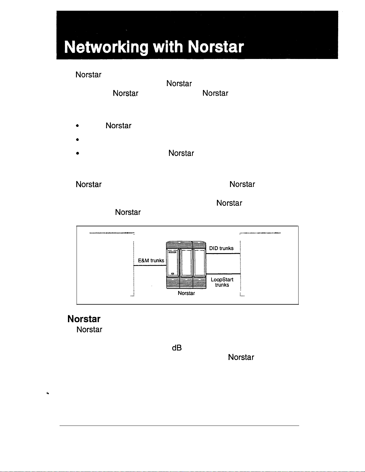
The Big Picture
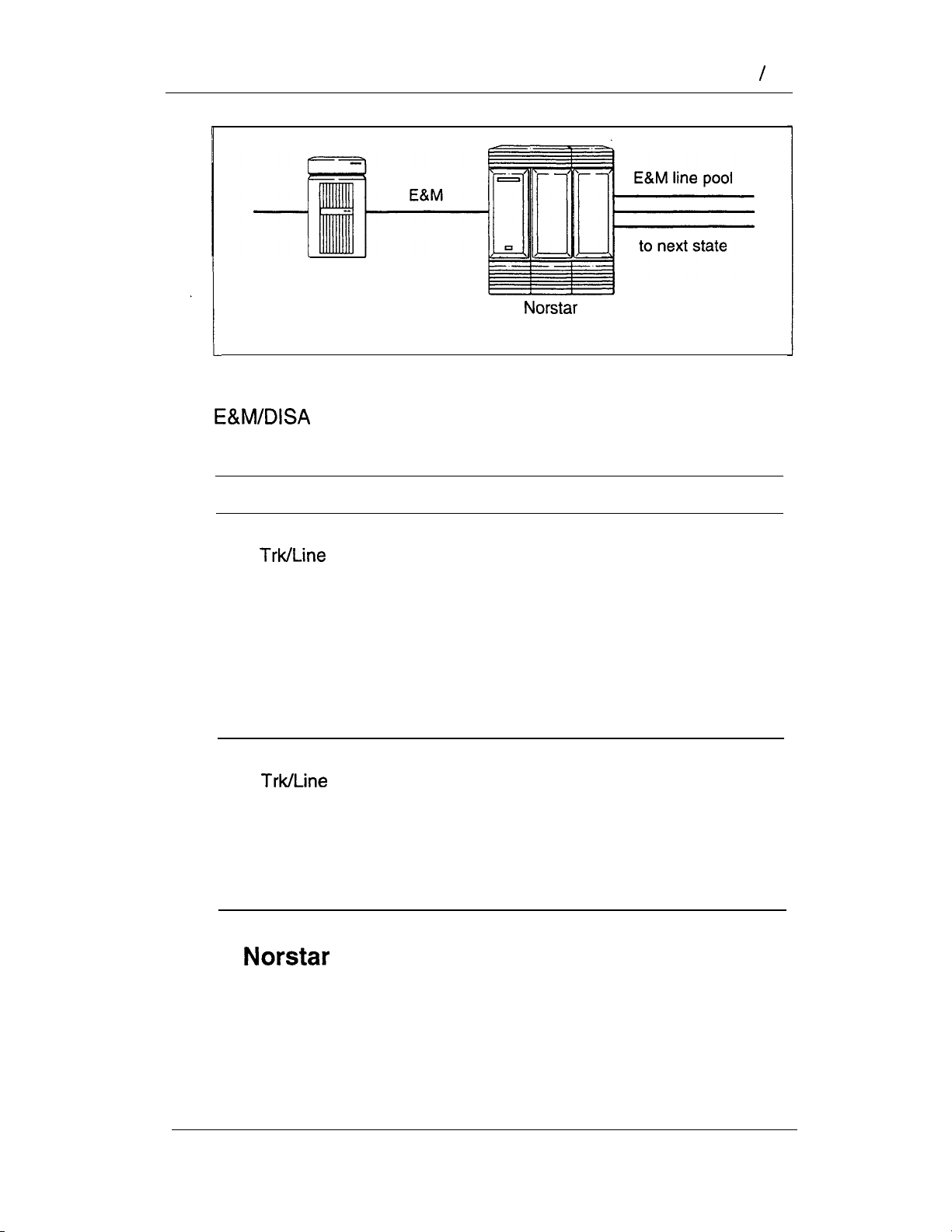
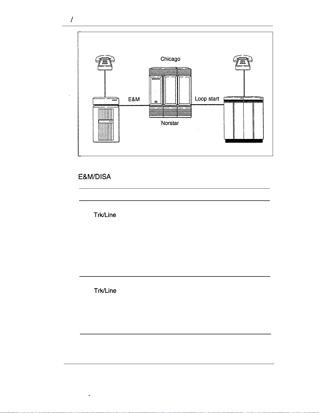
uses enhanced trunking to join other or customer
equipment in a private network. Authorized users can also
access tie-lines, Central Office lines, and
outside the
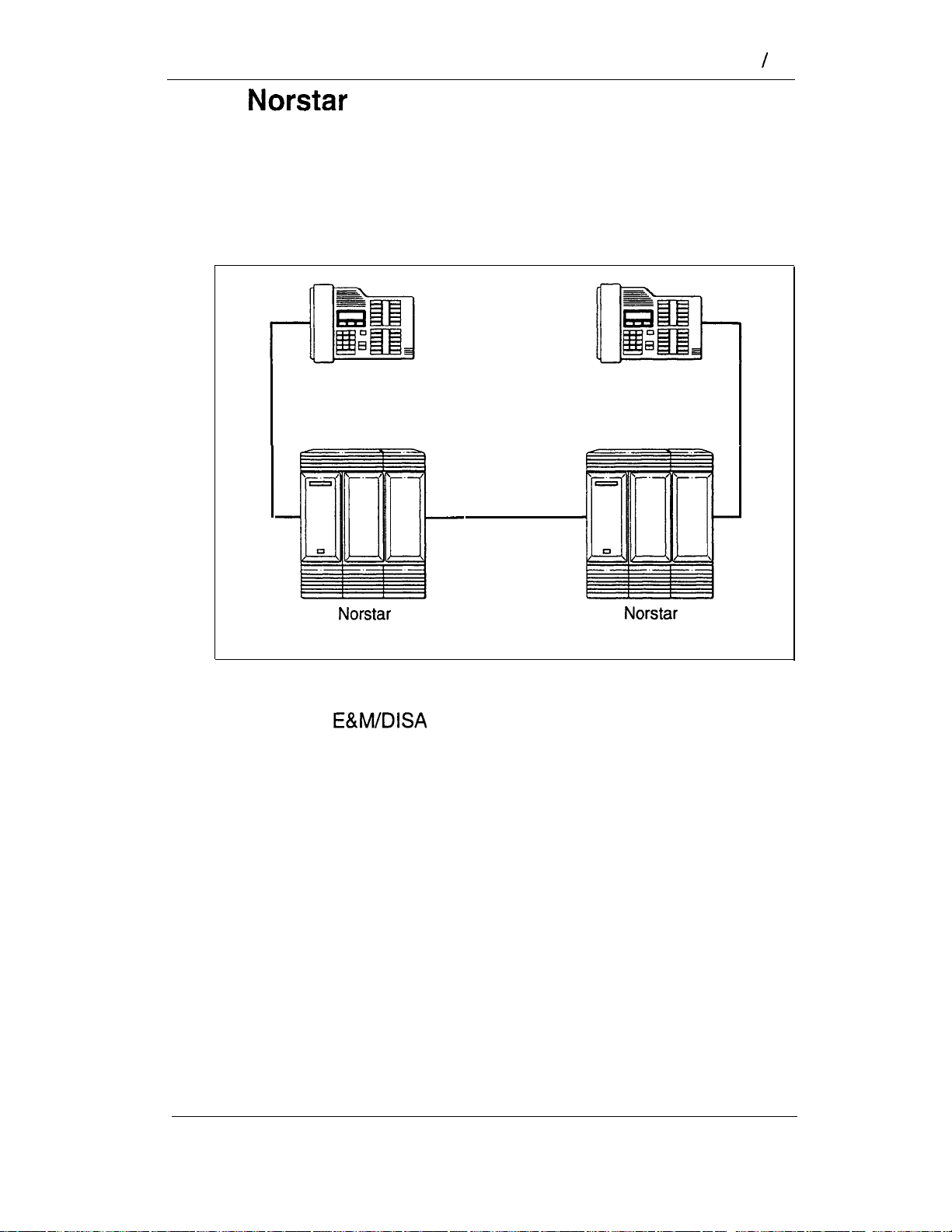
to an existing private network,
systems to form a network.
features from
system.
. . . Private network
Public network
as an OPX
can be used as an off premise extention (OPX) from a
PBX. In order to support this application, the OPX lines must be
engineered not to exceed 7
central office to the demarcation point at the
total loop loss from the serving
KSU.
Modular DR5 Installer Guide
Page 7
2 Networking with
Bits and pieces
The trunks and lines that uses make network access
possible. Target lines concentrate incoming calls on fewer trunks,
and three types of trunks provide the network access:
l
E&M trunks handle incoming and outgoing traffic between
the
DID trunks route incoming calls from the public network
directly to telephones within
l
loop start trunks handle incoming and outgoing calls between
and the public network.
Benefits
Security
provides the security that expanded access demands.
You can:
system and the private network.
without an attendant.
control remote access to tie-lines, Office lines, and
system features by setting up a specific Class of Service for
each type of caller,
l
restrict outgoing calls to certain telephone numbers or area
codes by applying dialing filters to lines and telephones, and
screen remote callers by configuring trunks to answer with
DISA, a system response that requires callers to enter a valid
password.
Unified dialing plan
When you link a number of systems into a network, you
can configure them so that the length of Directory Numbers
the line pools, and the line pool access codes are
consistent from one system to the next.
Call handling capabilities
In the system, the concentrated environment supports
call handling features on up to 184 lines, of which 80 are physical
trunks and 104 are target (virtual) lines.
Modular
Installer Guide
Page 8

Customer use
Callers in the public network can:
call directly to one or more telephones,
call into the system and select outgoing tie-lines to
access the private network,
call into the system and select outgoing Central
Office lines to access the public network, and
.
call into the system and use remote features.
Callers in the private network can:
call directly to one or more telephones,
l
call into the system and select outgoing tie-lines to
access other nodes in the private network,
call into the system and select outgoing Central
Office lines to access the public network, and
Networking with Not-star 3
call into the system and use remote features.
Callers in the
system can:
call directly to a specific telephone,
select outgoing tie-lines to access the private network,
select outgoing tie-lines to access features that are available
on the private network,
select outgoing Central Office lines to access the public
network, and
use all of the features.
Modular
Installer Guide
Page 9

4 Bits and Pieces
Bits and pieces
To understand the capabilities that are described later in this
chapter, you need to know how the trunks and lines behave in
the
system.
A trunk is a physical connection between the
the outside world. A line is a flexible communication path
between a
one-to-many relationship between trunks and lines.
What this means is that one trunk does not have to represent
one line, but can represent several lines. You achieve this in two
ways:
1. Auto-answer trunks
lines, you configure it as Auto-answer. The
answers calls and maps incoming digits onto numbers that
you define in programming. The numbers can access the
system, so that callers can then use selected features or call
out to another destination (calling through the system). The
numbers can also access target lines that appear on one or
more
2. Target lines
number of different target lines. These are virtual lines that
can appear on a
are incoming lines only, and cannot be selected for outgoing
calls. They are identified to the system by their number. Any
line with a number from 081 to 184 is a target line.
user and the outside world. This allows a
If you want one trunk to serve many
telephones.
incoming calls on one trunk can map onto a
telephone like any other line. They
system and
system
Of course, you can still have a one-to-one relationship between a
trunk and a line. In this case, you configure the trunk as
manual-answer.
You can read more on target lines in the Programming chapter.
To learn more about the types of trunks and the important
differences between auto-answer and manual-answer trunks,
read on.
Modular DR5 Installer Guide
Page 10
Loop start trunks
Loop start trunks give you incoming and outgoing access to the
public network. However, you would typically configure your
system with loop start trunks for outgoing calls and DID trunks for
incoming calls. Loop start trunks can be configured as
manual-answer or auto-answer.
When a call comes in on a manual-answer loop start trunk, it
alerts at all telephones with that line appearance.
When a call comes in on an auto-answer loop start trunk, you
hear a stuttered dial tone if the trunk is configured to answer with
DISA. Then you must use a DTMF telephone to enter a
Class of Service password.
When a call comes in on an auto-answer loop start trunk, you
hear the system dial tone if the trunk does not have DISA, or if
the Class of Service password is valid. Use a DTMF telephone to
enter a target line number, the DN, a line pool access
code, or a remote feature code.
Bits and Pieces 5
To place an outgoing call, select a loop start line by dialing a line
pool access code, pressing a line button on the telephone, or
pressing a memory button that has been programmed with a line
pool access, code.
Configuration ‘requirements
You need one Loop Start Trunk Cartridge or Cl Trunk Cartridge
for every four trunks beyond the eight that come with the Key
Service Unit. If you wish to configure your loop start lines as
auto-answer, the lines must have disconnect supervision. You
will also need one
start lines that you configure as auto-answer. An auto-answer
loop start trunk can give you the same kind of direct inward
dialing function as a DID trunk, but you will require
Trunk Cartridges to receive the incoming digits from the Central
Office.
Trunk Cartridge for every two loop
Modular DR5 installer Guide
Page 11

6 Bits and Pieces
You may configure a loop start line as the Prime line for a
telephone.
E&M trunks
An E&M trunk gives incoming and outgoing tie-line access from
other systems in the private network to the
trunks can be configured as manual-answer or auto-answer.
system. E&M
cartridges
. . . . . . . . . . . . . . . . . . . . . . . . . . . . . .
. . . . . . . . . . . . . . . . . . . . . . . . . . . . .
When a call comes in on a manual-answer E&M trunk, it alerts at
all telephones with that line appearance.
Modular
Installer Guide
Page 12
Bits and Pieces 7
When a call comes in on an auto-answer E&M trunk, you hear a
stuttered dial tone if the trunk is configured to answer with DISA.
Then you must use a DTMF telephone to enter a 6-digit Class of
Service password.
When a call that comes in on an auto-answer E&M Trunk, you
hear the system dial tone if the trunk does not have DISA, or if
the password is valid. Use a DTMF telephone to enter a target
line number, the DN (the number that will call for a Class of
Service password), a line pool access code, or a remote feature
code.
When a call comes in on an auto-answer E&M trunk from an
intelligent network, the system answers the call and
interprets the incoming digits:
l
If the digits map onto a target line, routes the call to
all
devices with an appearance of that line.
If the digits map onto the DN, you hear a stuttered dial
tone, and must use a DTMF telephone to enter a valid Class
of Service password to get the system dial tone.
If the digits map onto the Auto DN (the number for direct
system access), you hear the system dial tone, and can use
a DTMF telephone to enter a target line number, the
DN, a line pool access code, or a remote feature code.
To place an outgoing call, select an E&M trunk by dialing a line
pool access code, pressing a line button on the telephone, or
pressing a memory button that has been programmed with a line
pool access code.
Configuration requirements
In your configuration, one Trunk Cartridge is required
for every two E&M trunks. One
also required for every two DTMF receivers required for on
loop start trunks.
Trunk Cartridge is
You may configure an E&M trunk as the Prime line for a
telephone.
Modular DR5 Installer Guide
Page 13

8 and Pieces
DID trunks
DID trunks give you direct inward dialing (DID) from the public
network to the system. A typical application of these
trunks is to map incoming digits onto target line appearances
within the
auto-answer trunks.
system. DID trunks can operate only as
Target lines
084
I--
r
Central office
Modular DR5 Installer Guide
Page 14

Bits and Pieces 9
When a call comes in on a DID trunk, interprets the
incoming digits:
If the digits map onto a target line, routes the call to
all devices with an appearance of that line.
l
If the digits map onto the DN, you hear a stuttered dial
tone, after which you must use a DTMF telephone to enter a
valid Class of Service password to get the system dial tone.
If the digits map onto the Auto DN, or if the Class of Service
password is valid, you hear the system dial tone. Then you
can use a DTMF telephone to enter a target line number, a
line pool access code, or a remote feature code.
Configuration requirements
You need one DID trunk cartridge for every four DID trunks. Each
DID Trunk Cartridge has four DID trunks and four DTMF
receivers dedicated to those trunks.
You cannot configure a DID trunk as the Prime line for a
telephone.
Modular DR5 installer Guide
Page 15

10
Benefits
Benefits
Security
In the Capabilities section of Administration programming, there
are several ways of protecting your
unauthorized access.
Class of Service
Class of Service refers to the capabilities that provides to
users who access the system from the public or private network.
The Class of Service includes:
l
filters that restrict dialing on the line, and
an access package, which defines the set of line pools that
may be accessed and whether or not the user has access to
the paging feature.
system from
The Class of Service that is applied to an incoming
remote-access call is determined by:
the filters that you apply to the incoming trunk, or by
the Class of Service password that the caller used to gain
access to the
In cases where is not applied to incoming calls, the remote
caller can change the Class of Service by dialing the
and entering a Class of Service password.
To program Class of Service passwords, see Administration in
the Programming chapter.
system.
DN
Dialing filters
You can use dialing filters to restrict the numbers that may be
dialed on any external line within your
specify up to 100 dialing filters for the system. A dialing filter
consists of up to 48 restrictions and their associated exceptions.
system. You may
Modular
Installer Guide
Page 16
Benefits
11
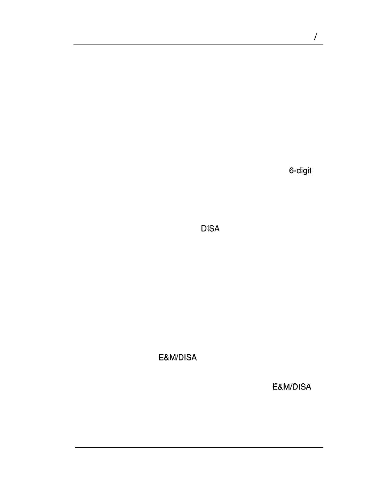
Dialing within the system
To restrict dialing within the system, you can apply dialing filters
to outgoing external lines (as line filters), to telephones (as set
filters), and to external lines on specific telephones (as line per
set filters).
Line
Filter
no long
line 1
Set
Filter
distance
distance
except area
codes 212.
718.214.713
line 1
1
no long
distance
line 5
Line per Set
Filter
no long
line 5
distance
except
area codes
Dialed digits must both the line filter and the set filter. The
line per set filter overrides the line filter and set filter.
In this diagram, a caller using line 1 could only dial long-distance
numbers to area codes 212 and 718. A caller using line 3 could
not dial any long-distance numbers. A caller using line 5 could
dial long-distance numbers to area codes 212, 718, and 415.
Set filters have no effect on the numbers that are dialed
on an E&M trunk.
Modular DR5 Installer Guide
Page 17
12 Benefits
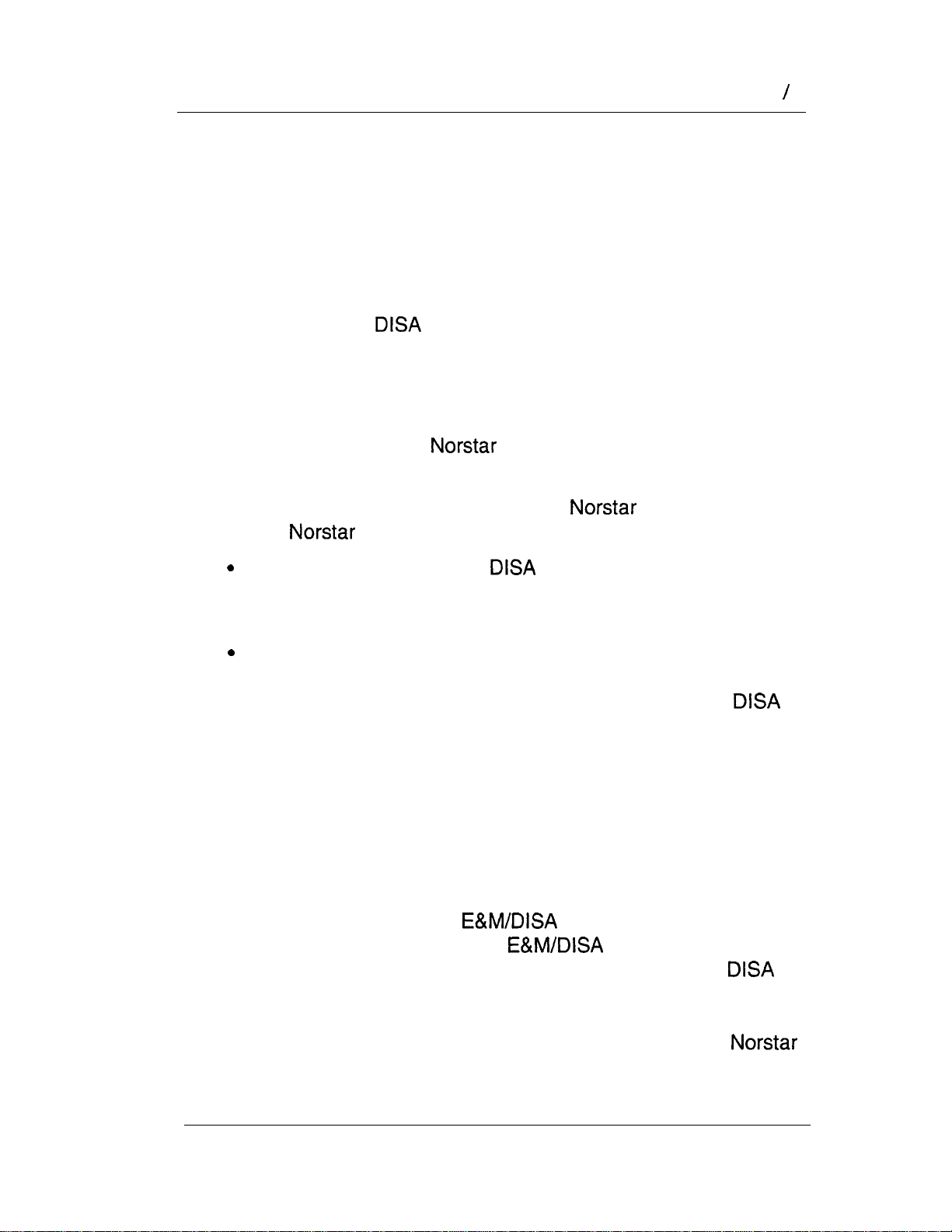
Dialing outside the system
To restrict dialing outside the system (once a caller gains remote
access), you can apply dialing filters to incoming external lines
(as remote filters).
Remote
caller
Line
Filter
In this case, dialed digits must pass both the remote filter and the
line filter. A remote caller can override these filters by dialing the
DN and entering a Class of Service password.
For programming instructions, see the Programming chapter of
this Installer Guide.
Direct inward system access (DISA)
To control access from the public or private network, you can
configure auto-answer trunks to answer with DISA. Remote
callers hear a stuttered dial tone and must then enter a Class of
Service password that determines what they are allowed to do in
the system.
Auto-answer loop start and E&M trunks are configured to answer
with
Note;’
by default.
You must have one Trunk Cartridge for every
two auto-answer loop start trunks.
Modular
Installer Guide
Page 18
Benefits 13
DID trunks cannot be configured to answer with DISA. If you
want incoming DID calls to be answered with DISA, configure the
system with a
DN are then routed to a line that has DISA.
For programming instructions, see the Programming chapter of
this Installer Guide.
DN. incoming DID calls that map onto the
Unified dialing plan
The system does not support a coordinated dialing plan
for other systems in the network. However, if you are configuring
more than one Nor-star system in your network, you can make
access between the systems much easier with a unified dialing
plan.
Directory Numbers
Make sure that the length of your is the same for all the
systems.
Line pools
If the systems are close to each other geographically,
you can conserve resources by not duplicating access. For
example, system A has a line pool to New York, System B has a
line pool to Los Angeles, and system C has a line pool to Dallas.
A
Dallas.
user in system A calls system C to get the line pool to
Line pool access codes
To simplify access between systems, all line pools that
go to the same destination should have the same line pool
access code. For example, system A and system B both have a
line pool to London. You can configure both systems with the
same line pool access code for the Nashville line pool.
Modular Installer Guide
Page 19
14 Benefits
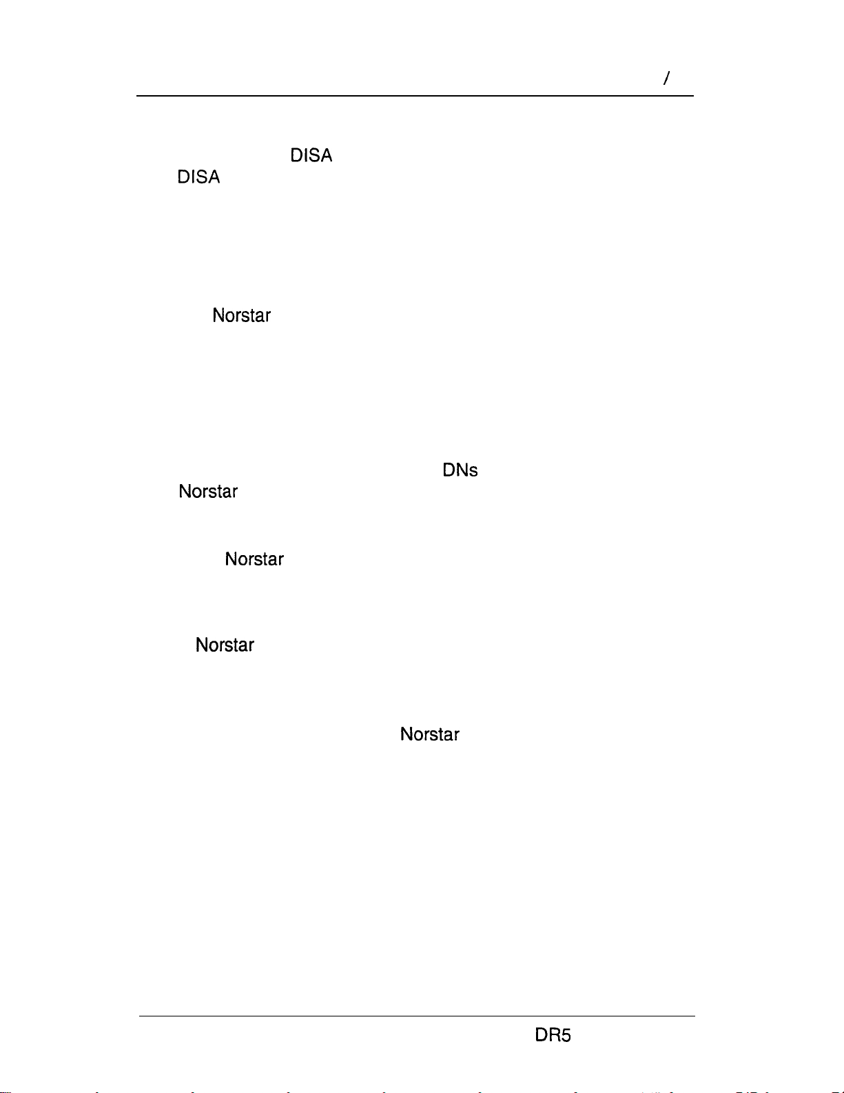
Unified dialing plan among four systems
A dialing plan similar to the one in the following figure will let you
create a company directory that includes the line pool access
codes.
E&M
Netwk #: 5234
Internal 234
System A
System D
Netwk
6334
System
E&M
System C
Netwk 8534
Internal
534
Internal
434
For instance, the person on System A at telephone 234 can
select an Intercom button and dial 7434.
This means that telephone 234 has dialed the line pool access
code of the trunk to System C, and will receive the dial tone of
System C. The digits 434 then map to the Received number 434,
and ring telephone 434 with an appearance of the associated
target line.
Modular DR5 Installer Guide
Page 20

Call handling with target lines
Having target lines with the system means that call
coverage is extended. All call handling features that apply to
regular lines also apply to target lines.
Here are some brief descriptions of features that apply to any line
appearance on a telephone. For complete information on
these features, see the Telephone features chapter of this
‘Installer Guide.
Auxiliary Ringing
If the system has an auxiliary ringer (a bell that is not part
of a telephone), the target line can be administered so that the
auxiliary ringer alerts in addition to the telephone ringer.
Callback
When an external call on a target line is transferred to a busy
telephone or not answered after a specified number of rings, the
call automatically rings at the Prime telephone for that line. The
display shows that the telephone was busy or that the call was
not answered.
Benefits 15
Camp on
Even when a telephone is busy, a call on a target line can be
routed to the telephone, where it waits in a queue until the
telephone is not busy.
Delayed Ring Transfer
Target line calls that go unanswered after a specified number of
rings can be routed to the Prime telephone if programmed to do
so in Configuration.
Held Line Reminder
When a target line call is placed on hold, the telephone gives two
reminder tones at periodic intervals until the call is taken off hold.
This happens only if Held reminder is activated during
Configuration programming.
Modular Installer Guide
Page 21

16 Benefits
Overflow Call Routing
If a call comes in for a target line that is busy, routes the
call to the Prime telephone for that target line. If you don’t assign
a Prime telephone for the target line or if a call cannot be
mapped onto a target line, the call will go to the Prime telephone
for the incoming trunk.
Prime Telephone Call Capture features
See the Prime Telephone User Card for details.
Privacy
When a user is on an external call and the Privacy
feature is turned on, no other
target line can join in on the call. If Privacy is turned off, another
person with the same line can press the line button to join your
conversation, forming a conference.
telephone with the same
Service Modes
When there are fewer people available to answer calls during
lunch hours, nights, or weekends, you can administer the system
so that target line calls ring at certain telephones.
Modular DR5 Installer Guide
Page 22

Customer Use 17
Customer Use
This section shows sample configurations for different types of
network access. Each example has four parts:
A scenario explains the caller’s goal and what is required to
achieve it.
A diagram shows the network configuration that supports the
l
application.
.
A list shows the
configuration.
Tables show the Configuration and Administration
l
programming required. Only those settings that are important
to network access are described here.
hardware required to support the
Modular Installer Guide
Page 23

18
Customer Use
In the public network
Call one or more telephones
Ms. Nelson is a bank customer who has a question for an
accountant. She dials the telephone number that maps onto
target line 083. All of the accountants’ telephones ring.
Ms. Nelson
Target line
083
Accountant
Accountant
(telephone 226)
Central office
Hardware:
any version of KSU, one Trunk Module, one DID
Trunk Cartridge.
Heading
1. Data
5. System Data
Parameter
Rec’d #
Line 009
Rec’d # length 4 (can be up to 7
Setting
4321 (for Line 083)
DID
digits, but must match
number of digits sent
by Central Office)
Modular Installer Guide
Page 24
Customer Use
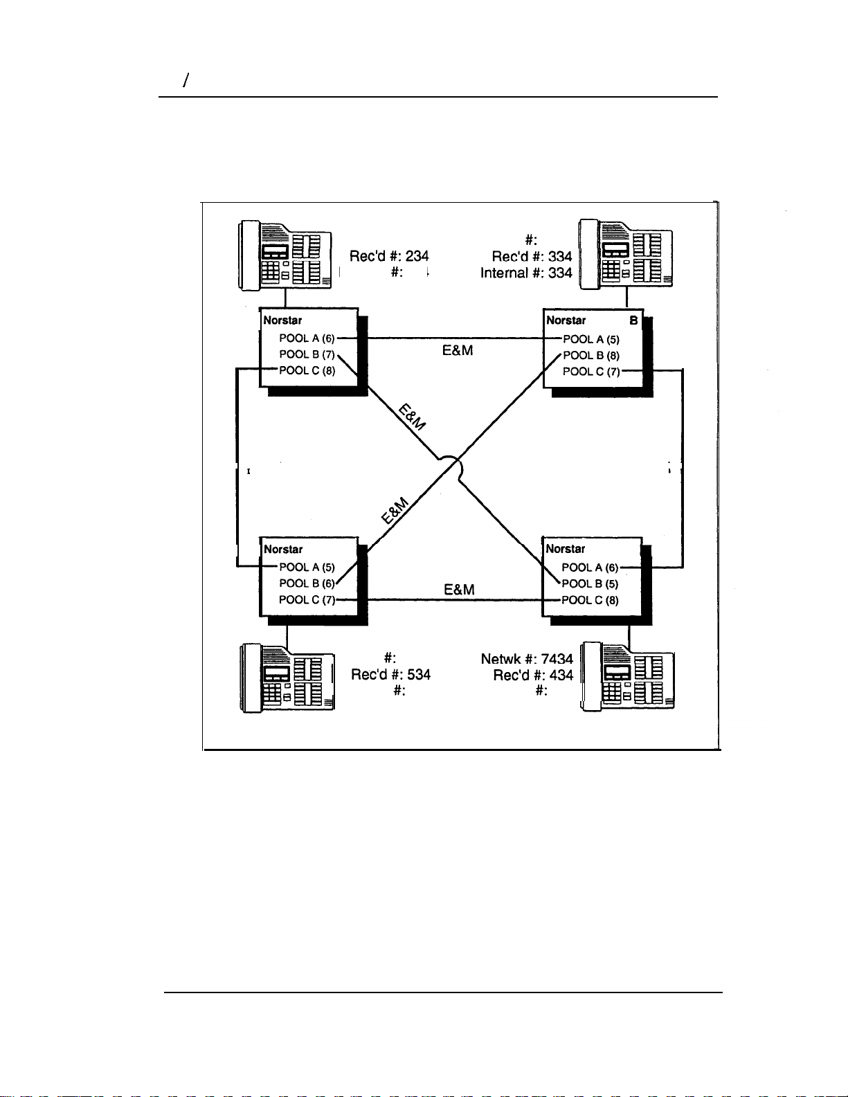
Call and select tie lines to a private network
A manager in Georgia wants to use the tie lines at headquarters
to call Washington. He dials a telephone number that maps onto
the
dials a line pool access code to select a tie line to Washington.
DN, enters a Class of Service (COS) password, then
Central office
19
Hardware:
any version of KSU, one Trunk Module, one DID
Trunk Cartridge, two Trunk Cartridges (for the three
trunks in the line pool to Washington).
Heading
Incoming trunk:
1.
4. Miscellaneous
5. System Data
Outgoing trunk:
1.
4. Miscellaneous
5. Capabilities
Data
Data
Parameter
Line 009
DN
Rec’d
Line 013
Line type
Line pool F
length
Setting
DID
5321
4 (can be up to 7
digits, but must match
number of digits sent
by Central Office)
E&M
Pool F
6 (up to 4 digits)
Define filters: Define
remote access pkgs.
Assign a dialing filter
to the line. Assign
COS passwords and
filters for each class
of service.
Modular DR5 Installer Guide
Page 25
20 Customer Use
Call and select lines to the public network
Gord wants to make a long-distance business call from home. To
avoid being charged, he dials the telephone number that maps
onto the Auto DN at work. After hearing the dial tone, Gord dials
a line pool access code to select a line to the public network. He
then dials the long-distance number.
r
Gord
at home
Business
client
Central office
Hardware:
any version of KSU, one Trunk Module, one DID
Trunk Cartridge.
DID
Line
Central office
Modular Installer Guide
Page 26

Customer Use 21
Heading
Incoming trunk:
1.
4. Miscellaneous
5. System Data
5. Capabilities
Outgoing trunk:
1.
Data
Data
Parameter Setting
Line 009
Auto DN
Rec’d # length
Line 001
Line type
DID
4321
4 (can be up to 7
digits, but must match
number of digits sent
by Central Office)
Define dialing filters.
Define remote access
packages. Assign a
remote filter and
remote package to
the line.
Loop
Pool A
4. Miscellaneous
5. Capabilities
Line pool A
1234
Assign a dialing filter
to the line.
Modular DR5 Installer Guide
Page 27

22 Customer Use
In the private network
Call one or more telephones
The production supervisor in Houston selects the less-expensive
company tie line to call the manager at the Administration office
in Dallas. Once the line is selected, the production supervisor
dials the digits that will map onto the target line of the manager in
Dallas.
target line
083
PBX in
Houston
Hardware
E&M
: any version of KSU, one Trunk Module, one
Trunk Cartridge.
Heading Parameter Setting
incoming trunk:
1. Data
5. System Data
Rec’d #
Line 009
Ans Mode
Rec’d # length 4 (can be up to 7
4321
083)
E&M
Auto
digits, but must match
number of digits sent
by Central Off ice)
Manager
in Dallas
(for target line
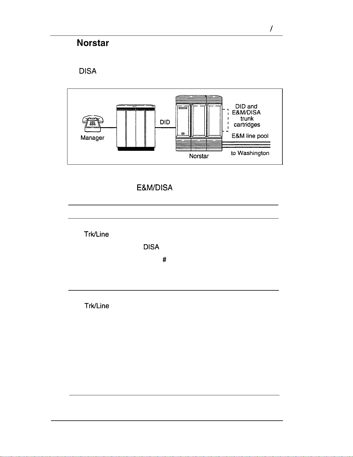
Call and select tie lines to other nodes in the
private network
At a branch office, Joan selects a tie line to the government office
downtown. After hearing the dial tone, she dials a line pool
access code to select another tie line to a government office in
the next town.
Modular Installer Guide
Page 28
Key system
Customer Use 23
Hardware:
any version of KSU, one Trunk Module, two
Trunk Cartridges (for the three lines in the line pool
and the one incoming line)
Heading
Incoming trunk:
1.
5. Capabilities
Outgoing trunk:
1.
4. Miscellaneous
Data
Data
Parameter
Line 009
Ans mode
Line 010
Line type
Line pool D
Setting
E&M
Auto
Define dialing filters.
Define remote access
packages. Assign a
remote line filter and
remote package to
the trunk.
E&M
Pool D
71 (up to 4 digits)
5. Capabilities
Assign a dialing filter
to the trunk.
Call and select lines to the public network
Liz needs to call long-distance to a client in Toronto. She selects
a tie-line to the branch office in Toronto. After hearing the dial
tone, she dials a line pool access code to select a line to the
public network. Then, she dials the client’s number as a local call.
Modular DR5 Installer Guide
.
Page 29
24 Customer Use
Liz in
Memphis
Key system
Hardware:
Client in
Toronto
Central office
any version of KSU, one Trunk Module, one
Trunk Cartridge.
Heading
Incoming trunk:
1.
5. Capabilities
Outgoing trunk:
1.
4. Miscellaneous
5. Capabilities
Data
Data
Parameter Setting
Line 009
Ans mode
Line 001
Line type
Line pool B
E&M
Auto
Define dialing filters.
Define remote access
packages. Assign a
remote filter and
remote package to
the trunk.
Loop
Pool B
73 (up to 4 digits)
Assign a dialing filter
to the line.
Modular DR5 Installer Guide
Page 30
Customer Use 25
In the system
Select tie trunks to the private network
. For a confidential call, the Montana sales manager presses the
line button for a private E&M trunk to the Oregon office. This
automatically alerts at the line appearance on the telephone of
the Oregon sales manager.
Montana
Sales Manager
E&M
Hardware:
(for both systems) any version of KSU, one Trunk
Module, one Trunk Cartridge
Oregon
Sales Manager
Modular DR5 Installer Guide
Page 31

26 Customer Use
Heading
Outgoing trunk
(Montana):
Trunk Data
(Line 009)
Line Data
(Line 009)
Incoming trunk
(Oregon):
Trunk Data
(Line 009)
Parameter Setting
Line
Line type Private
Line
Ans mode
Line type
E&M
E&M
Manual
Private
Modular installer Guide
Page 32

A System Feature
Line Redirection feature
I””
target line
092
Branch office
I
I
Customer Use 27
line 3
,
incoming call
redirected
call
The branch office is receiving more calls than it can handle, so it
redirects one of its lines to the main office. All calls that come in
on target line 092 will be routed out on line 003 to the
office.
Whenever a call is redirected, the target line and outgoing line
will be busy for the duration of the call.
Hardware
: Version 2 or higher KSU, an Trunk
Cartridge if the incoming trunk is E&M, or a DID Trunk Cartridge
if the incoming trunk is DID.
Note:
Any line appearance on a telephone can be
selected as the incoming line to be redirected. A
target line can not be selected as the outgoing
line for redirection.
The incoming trunk must have disconnect
supervision.
Modular DR5 Installer Guide
Page 33

28 Customer Use
Program heading
Incoming trunk:
1.
5. System Data
Outgoing trunk:
1. Data
Data Line001
Trunk mode:Super
Ans mode:Auto
OR
Line 009:DID
OR
Line
Ans mode:Auto
Rec’d 1
(for target line 092)
Rec’d # length:4 (can be up to 7
digits, but must match number
of digits sent by Central Office)
Line 003: Loop
OR
Line01
Branch office set:
5. Capabilities
Allow redirect:\/
Modular DR5 Installer Guide
.
Page 34

Check the location where the system modules, the
telephones, and auxiliary equipment are to be installed. This
includes making sure sufficient space is available to install the
components.
Location requirements
Clean, dry, and well-ventilated
Temperature: to 50°C (32°F to 122°F)
Humidity: 5% to non-condensing
Location: at least 4 m (13.1 ft) from equipment such as
photocopiers, electrical motors, and other equipment that can
produce electromagnetic, radio frequency, and electrostatic
interference.
Electrical requirements
Non-switched outlet
ac outlet located not more than 1.5 m (4.9 ft) from the Key
Service Unit (KSU). The actual distance from the KSU to the
Power Bar may vary with additional Trunk and Station
Modules. Do not use an extension cord between the KSU
and the power bar.
For the 110 V system
Dedicated 110-V ac nominal, 15-A minimum
service with third wire ground.
the 220 V system
Dedicated to 240-V ac nominal,
10-A minimum service with third wire ground.
WARNING
The ac outlet must be equipped with a third wire ground
to avoid electromagnetic interference.
Modular Guide
Page 35

30 installation
Internal wiring requirements
All new or existing wiring for telephones must meet the
following specifications:
one twisted pair per telephone
a dc loop resistance less than 59
cable length (0.5 mm or 24 AWG) not to exceed 305 m
(1000 ft)
use of a Station Auxiliary Power Supply (SAPS) to
extend the loop up to 790 m if the cable is longer than 305 m
(1000 ft)
no bridge taps
Installers should also check the lightning protectors at
the cable entry point to the building with special attention
to the grounding. Any problems should be reported to
the telephone company in writing.
wiring should not leave the buildings as it is not
lightning-protected.
WARNING
telephone
Mounting requirements
If a smooth surface is not available, cut a backboard large
enough to accommodate the system modules and the distribution
block. The system module physical dimensions are listed in this
chapter.
Equipment ‘for mounting the modules
screwdriver, diagonal cutters, pliers, connecting tool, pencil,
level (optional)
four 1 long wood screws for the KSU and four for
each of the expansion modules
(1 %-in) long screws for the cable troughs
thick wooden backboard (if necessary)
Modular DR5 Installer Guide
Page 36

Module installation 31
Module installation
Key System Unit (KSU)
The Key Service Unit (KSU) is the hub of the Not-star System. It
can function on its own as a basic system (with up to 24
telephones and eight external lines). The system may also be
expanded with any combination of up to six Trunk Modules
and/or Station Modules.
LED
CO Lines connector
Feature cartridge (2 parts)
Cable clips
Stations connector
Expansion cartridge
cartridge shown)
Half-size
Cable trough
Modular DR5 Installer Guide
Page 37

32 Module installation
Trunk Module (TM)
The Trunk Module allows additional Trunk Cartridge installation.
This in turn allows more external lines to be connected to the
system. The Trunk Module has three slots in front for
inserting Trunk Cartridges. Each Trunk Module can add a
maximum of 12 external lines (four external lines per Trunk
Cartridge). Different types of Trunk Cartridges can be mixed in
one Trunk Module. When mixing Trunk Cartridges, use a
separate distribution block for each type of Trunk Cartridge.
Slot for Trunk cartridge
(face plate removed)
Protective faceplates
covering unused slots
LED
DS-30 port
Cable clip
connector
Trunk cartridge
Half-size
Cable trough
Modular Installer Guide
Page 38

Module installation 33
Station Module (SM)
The Station Module allows up to 16 additional telephones
to be connected to the system. A DS-30 cable connects each
Station Module to the KSU.
LED
DS-30 port
Cable clips
50-pin connector
Cable clips
Quarter-size
Cable trough
Modular DR5 Installer Guide
Page 39

34 Module installation
Recommended layout
The Key Service Unit (KSU), Trunk Modules (TM), and Station
Modules (SM) can be mounted in any order. Allow suitable wall
space for installing future Trunk and Station Modules.
S
r
dimensions
If possible, leave
enough room for
future expansion
TM SM
mm (15.5 in.)+
698 mm
Widths
L
Additional dimensions of KSU, TM SM
Dimension
KSU
TM
SM
Clearance
(front)
Modular DR5 Installer Guide
171
(6.7
346
(13.6
7.5
Kg
(16.6
mm
in)
mm
in)
lb)
4.3
Kg
(9.5 lb)
2.4
(5.3
Kg
lb)
Page 40

Module installation 35
Remember
Leave about 15 centimetres (6 inches) of space above the screw
holes of the mounting bracket. This allows room to slide the KSU,
Trunk Module and Station Module on and off the bracket and
provides space for venting the heat from the modules.
Bottom
Ensure there is at least 10 centimetres (4 inches) of space
between the bottom of the cable trough and the floor, or any
object that may block the flow of air from the bottom for cooling.
CAUTION
All modules must be mounted well above the floor to
prevent water damage.
Sides
Mount the distribution block on the left side of the KSU. Leave
enough room to mount additional Trunk Modules and Station
Modules on the right side.
Front
Leave enough room to allow the doors of the modules to open
and the cabling to run on the side.
Between modules
The space between two modules hung on the mounting brackets
is approximately
Note:
Refer to the illustration showing the system dimensions
mm in).
for additional module clearance requirements.
CAUTION
Mount the KSU vertically to avoid overheating.
Modular DR5 Installer Guide
Page 41
36 Module installation
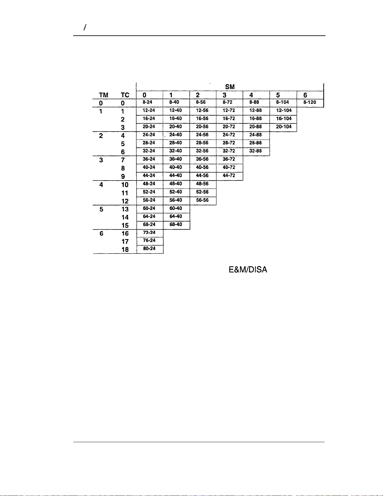
System hardware configuration
This chart shows combinations of Trunk Modules, Trunk
Cartridges, and Station Modules for expanding the system.
Possible line and station configurations
Note:
Number of physical lines shown is for Loop Start, DID,
and Cl Trunk Cartridges only.
Cartridges provide half the number of lines.
Trunk
Modular DR5 Installer Guide
Page 42

Module installation 37
How to read the hardware chart
To find the maximum number of lines and telephones for a
particular configuration of KSU, Trunk Module(s), and Station
Module(s):
1.
Find the number of Trunk Modules in the left column. The
column labeled “TC” gives the number of Trunk Cartridges.
2.
Find the number of Station Modules in the top row.
3.
Read across to the right from the Trunk Module column and
down from the Station Module row.
A pair of numbers indicates lines and telephones for that
combination of Trunk Modules and Station Modules. The left
number is the maximum number of external lines. The right
number is the maximum number of telephones.
Examples:
8-24
12-24 =
12-40 =
=
8 lines and 24 telephones (KSU without Trunk
Modules or Station Modules).
12 lines and 24 telephones (KSU lines and
telephones, plus one Trunk Module and one Trunk
Cartridge with 4 more lines, and no Station
Modules).
12 lines and 40 telephones (KSU lines and
telephones, plus one Trunk Module and one Trunk
Cartridge with 4 more lines, and one Station Module
with 16 more telephones).
Modular DR5 Installer Guide
Page 43

38 Module installation
Mounting a module
1.
Position metal mounting bracket(s) on the wall or on the
backboard. Fasten the brackets with
in) screws.
Hint:
2.
Slide the KSU, Trunk Module, or Station Module down onto
the mounting brackets. Line up with the notches on either
side of the mounting bracket as you slide the module onto
the mounting bracket(s). This facilitates accurate hanging.
3.
Slide the cable trough(s) up under the appropriate module(s).
The KSU requires two half-size cable troughs. A Trunk
Module uses one half-size cable trough, while an Station
Module uses a quarter-size cable trough.
Open each cable trough door and let the door swing open.
5.
Fasten the cable trough to the wall with long screws.
Each cable trough requires two screws through the holes
provided in the lower tray of the cable trough.
6.
Close the doors of the cable troughs.
Before positioning the mounting brackets, draw a line
using a level and a pencil. This will help align the
modules.
7.
Do
not
connect power at this point.
Installing the KSU mounting bracket
Modular Installer Guide
Page 44

Module installation 39
Installing the cable troughs
Modular DR5 Installer Guide
Page 45

40 Module installation
Trunk Module. and Station Module installed
Key Service Unit (KSU)
Feature
Expansion
cartridge
shown)
Note:
Station
Module
Cable trough
(l/2-size)
Cable trough
For clarity, the illustration shows a KSU, a Trunk Module,
and an Station Module without doors. The doors should
not be removed during installation or operation. Also
shown are the Feature, Expansion, and Trunk Cartridges
which are installed later.
Modular DR5 Installer Guide
Page 46

Module installation 41
Installing the Feature Cartridge
The Feature Cartridge is made up of a Software Cartridge and a
Data Cartridge. The Software Cartridge contains the system
programming. The Data Cartridge contains the data from
Configuration and Administration programming.
When there is a software upgrade, only the Software Cartridge,
and not the Data Cartridge, needs to be replaced.
CAUTION
Do not touch the printed circuit board inside the cartridge
casing. This is an electrostatic-sensitive device.
1.
Turn the KSU power OFF before installing or removing a
Feature Cartridge.
Make sure you are wearing a grounding strap when handling
cartridges.
3.
Insert the Software Cartridge into the Data Cartridge.
4.
Insert the Feature Cartridge assembly into the KSU.
Unassembled and
assembled Feature
Cartridges
Installing the Feature
Cartridge
Modular Installer Guide
Page 47

42 Module installation
Installing an Expansion Cartridge
The two-port Expansion Cartridge allows up to two additional
modules (Trunk Modules and/or Station Modules) to be
connected to the system. The six-port Expansion Cartridge
allows the connection of up to six additional Trunk or Station
Modules. This Cartridge fits into the right slot of the Key Service
Unit (KSU).
Two-port Expansion
cartridge
Six-port Expansion
cartridge
Modular Installer Guide
Page 48

Module installation 43
The procedures for installing the Two-port and Six-port
Expansion Cartridges are identical. (Refer to the Port Numbering
information in this Guide for changes to default internal number
length caused by installing an Expansion Cartridge.)
CAUTION
Do not touch the printed circuit board on the Expansion
,
1.
2.
Cartridge. This is an electrostatic-sensitive device.
Make sure that the KSU power is OFF before installing or
removing an Expansion Cartridge.
Remove the cover of the
Expansion Cartridge slot
in the KSU. Use a
screwdriver at the bottom
of the cartridge slot cover
to help detach the
cartridge slot cover from
the slot.
3.
Make sure you are wearing a grounding strap when handling
any cartridge.
4.
While holding the latches
open, insert the Expansion
Cartridge in the
appropriate slot and close
the latches at the same
time to align the cartridge
properly.
Modular Installer Guide
Page 49

44 Module installation
Installing a Trunk Cartridge
The Trunk Cartridge, when inserted in a Trunk Module, adds up
to four external lines to the
Trunk Cartridges can be installed in each Trunk Module.
There are four types of Trunk Cartridges:
the Loop Start Trunk Cartridge (4 lines)
the Trunk Cartridge (2 lines)
the DID Trunk Cartridge (4 lines)
l
the Cl Trunk Cartridge (4 lines)
The Loop Start Trunk Cartridge supports regular external lines.
The
network. The DID Trunk Cartridge supports direct inward dialing
on incoming external lines. The Cl Trunk Cartridge supports Call
Display features on external lines.
Trunk Cartridge connects to a private
system. A maximum of three
Trunk Cartridges
Loop Start
DID
Cl
Different Trunk Cartridges can be installed in one Trunk Module if
required for a particular installation. When mixing Trunk
Cartridges, use a separate distribution block for each type of
Trunk Cartridge.
Modular DR5 Installer Guide
Page 50

Module installation 45
The procedures for installing the different Trunk Cartridges are
identical. See the wiring charts in this Guide for details.
CAUTION
I
Do not touch the printed circuit board on the Trunk
Cartridge. This is an electrostatic-sensitive device.
1.
Make sure that the Trunk Module power is OFF before
installing or removing a Trunk Cartridge.
2. Remove the appropriate
cartridge slot cover of an
unused Trunk Cartridge slot
on the Trunk Module. Use a
screwdriver at the bottom of
the cartridge slot cover to
detach the cover from a
Trunk Cartridge slot.
The numbers on the cartridge slots indicate the order
that the cartridges should be installed. If an
or a DID Trunk Cartridge is installed in
slot 1, Emergency telephones cannot be supported.
3.
Make sure you are wearing a grounding strap when handling
cartridges.
4.
While holding the latches open,
insert the Trunk Cartridge in the
appropriate slot and close the
latches at the same time to
align the cartridge properly.
Modular DR5 Installer Guide
Page 51

46 Module installation
Upgrading the Software Cartridge
Before installing a Modular DR5 Cl Trunk Cartridge or Call
Identification Interface (CII), the KSU system Software Cartridge
must be upgraded to DR5.
There are two possible situations where a software upgrade is
necessary:
1.
upgrading from a DR2 Software Cartridge, or
2.
upgrading from either a DR3 or a DR4 Software Cartridge.
Upgrading from DR2
If you are upgrading from a DR2 Software Cartridge, you must
first upgrade to DR3 software.
When a DR3 Feature Cartridge is plugged into a DR2 KSU, an
automatic upgrade takes place. In order to allow remote
programming of the NVRAM and prevent the automatic upgrade,
the following should be done:
Insert the Cartridge into the Data Cartridge prior to
installing in the system.
Place the new DR3 Feature Cartridge assembly into a
2.
captive KSU with the appropriate Two-port or Six-port
Expansion Cartridge, and power up the system.
Perform the Administration programming appropriate for the
3.
customer’s site. This will maintain their DR2 programming.
Change the Time and Date (either the hour or minutes, or
4.
both). This sets a lock on the NVRAM data so that it cannot
be updated.
Power down the captive KSU, remove the DR3 Feature
5.
Cartridge and take it to the customer site. To return a DR3
Feature Cartridge to the state where an automatic upgrade
will occur, perform ** Startup on it while it is in the captive
KSU.
Modular DR5 Installer Guide
Page 52

Module installation 47
Continue with the following procedure to install the DR3 Feature
Cartridge assembly in the customer’s KSU.
1.
Make sure that the KSU power is OFF before installing or
removing the DR3 Feature Cartridge assembly.
2.
Make sure you are wearing a grounding strap when handling
a cartridge.
3.
Insert the DR3 Feature Cartridge assembly into the KSU.
Once you have completed the upgrade to DR3 you can continue
with the next procedure to upgrade from DR3 to DR5 software.
Upgrading from DR3 or DR4
1.
Ensure that there is no call activity by informing all
users that the system will briefly be out of operation.
Turn OFF the KSU power (unplug the power cord).
2.
While wearing a grounding strap, remove the Feature
3.
Cartridge from the KSU.
4.
Remove the Software Cartridge from the Data Cartridge.
Insert the new Software Cartridge into the Data Cartridge.
5.
Insert the new Feature Cartridge into the KSU.
6.
Turn ON the KSU power (plug in the power cord)-.
7.
Modular DR5 Installer Guide
Page 53

48 Wiring
Wiring
Cable routing in the cable trough
Cable troughs beneath the Trunk Module, and Station
Module hold the 25-pair cables, the DS-30 cables, the power
cord(s), and the Power Bar (if required).
The cable troughs have been designed to keep the ac power
cords and Power Bar separate from the connecting cables and to
allow ease of access. Place the cabling in the two shelves, as
described in the following chart and pages.
Upper shelf
Lower shelf
All cables and DS-30 cables:
Place
Place the DS-30 cables in the front.
All power cords and the Power Bar(s).
cables in the back.
WARNING
To avoid electrical shock, hazard to personnel, or
equipment.damage, observe the following precautions
when installing telephone equipment:
l
Never install telephone wiring during a lightning storm.
l
Never install telephone jacks in wet locations unless
the jack is specifically designed for wet locations.
l
Never touch non-insulated telephone wires or terminals
unless the telephone line has been disconnected at the
network interface.
Modular DR5 Installer Guide
Page 54

Connecting internal wiring
To connect the internal telephones, each KSU and Station
Module requires one
female 50-pin connector at one end. Enough 50-pin distribution
blocks are required to accommodate the internal wiring.
1.
Plug the co
into the station connector on the KSU or the
Station Module. (The connector is labeled
with an icon representing a telephone.)
2.
Route the cable(s) through the upper shelf of the cable
troughs to the distribution block.
Note: Route the cables straight out to one side of the cable
trough in a bundle. Use cable ties to secure them to
the wall and to support their weight.
3.
Connect the wires to the appropriate pins on the distribution
block. (Refer to the wiring charts in this Guide.)
nnector of a cable
(24-AWG) cable with a
Wiring 49
4.
Cross-connect the KSU and Station Module telephone wires
to the corresponding station pins on the distribution block.
(Refer to the wiring charts in this Guide.)
5.
Using a single pair of wires for each telephone, connect each
of the telephones according to the wiring charts.
Connecting to the KSU
Connecting to the Station
Module .
Modular DR5 Installer Guide
Page 55

50 Wiring
Connecting external lines
To connect the external lines and auxiliary equipment, each KSU
and Trunk Module requires one
terminated with a female 50-pin connector on one end. A
distribution block is required for each
1.
Plug the connector of a cable into the external
line connector on the KSU or the Trunk Module. (The
connector is labeled with an icon representing telephone
poles.)
2.
Route the cable(s) through the upper shelf of the cable
trough to the
block.
0.5mm (24-AWG) cable
cable.
Note:
3.
Cross-connect the external lines to the distribution block.
(Refer to the KSU and Trunk Module external line wiring
charts and wiring arrangement diagrams in this Guide.)
4.
Connect the auxiliary equipment lines to the distribution
block. (Refer to KSU and Trunk Module external line wiring
charts and wiring arrangement diagrams in this Guide.)
Note: Auxiliary equipment cannot be connected to the
Route the cables straight out to one side of the cable
trough in a bundle. Use cable ties to secure them to
the wall and to support their weight.
RJ-21 interface.
Modular DR5 Installer Guide
Page 56

Wiring 51
5.
Connect external lines to a standard RJ-21 interface:
Bring the external cable to the distribution block and use the
distribution block to cross-connect to the corresponding KSU
and Trunk Module external lines according to the KSU and
Trunk Module external line wiring charts and diagrams. Refer
to the following charts and illustrations in this Guide:
Wiring arrangement for KSU
Wiring arrangement for Trunk Module
KSU external lines and auxiliary equipment wiring
Loop Start/Cl Trunk Cartridge wiring chart
6.
Wire the auxiliary equipment lines separately. (Refer to the
KSU and Trunk Module external line wiring charts and
diagrams.)
Note: For the Trunk Module, the auxiliary equipment line is
an Emergency Telephone (ET).
Connecting the KSU
external lines
Connecting the Trunk
Module external lines
as an OPX
can be used as an off premise extension (OPX) from a
PBX. In order to support this application, the OPX lines must be
engineered not to exceed 7 total loop loss from the serving
central office to the demarcation point at the KSU.
,
Modular DR5 Installer Guide
Page 57

52 Wiring
Connecting DS-30 cables
Plug one end of the DS-30 cable into the DS-30 port on the
front of a Trunk Module or Station Module.
2.
Route the cable through the cable clips on the right side of
the Trunk Module or Station Module.
3.
Route the cable through the upper shelf of the cable trough
to the KSU and up through the cable clip to the Expansion
Cartridge.
4.
TM DS-30 into
the
port and work DOWN.
available
Plugging in a Trunk Module
DS-30 cable
Plug SM DS-30 into
the LOWEST available
port and work UP.
Plugging in a Station
Module DS-30 cable
Modular Installer Guide
Page 58

Emergency telephones 53
Emergency telephones
Emergency telephones (ET) are standard single-line
telephones that provide emergency service in case of power
failure or
The KSU has two emergency telephone connections. Each
Trunk Module has one emergency telephone connection.
Connecting emergency telephones
The procedure is the same for connecting emergency telephones
to the distribution block for a KSU or a Trunk Module.
Wire a modular jack or equivalent to each set of emergency
telephone pins on the distribution block for KSU or
Trunk Module external lines.
power to the system is disconnected.
The connections on the distribution block for emergency
telephones appear in the wiring charts in this Guide.
Note:
Connect a single-line telephone to the modular jack.
2.
The emergency telephone connections will not work
if there is an
the first slot of the Trunk Module.
or DID Trunk Cartridge in
Modular DR5 Installer Guide
.
Page 59

54 Emergency telephones
Testing the emergency telephones
The emergency telephones must be tested with the power OFF
at the KSU and Trunk Module.
Pick up the receiver of the emergency telephone.
2.
Listen for the dial tone.
If you hear a dial tone, both the emergency telephone and
the line are functioning properly.
If you hear no dial tone:
Verify that power to the KSU and Trunk Module(s) is
OFF.
Check that the external line and emergency telephone
connections have been made correctly.
Ensure that the emergency telephone is not faulty, by
connecting it directly to the external line and listening for
dial tone.
Verify that there is dial tone on lines 1 and 2 of the KSU
and on line 1 of the Trunk Module.
3.
If all previous steps have been verified and there is still no
dial tone at the emergency telephone, replace the KSU if the
emergency telephone is connected to the KSU, or replace
the Trunk Module if the emergency telephone is connected to
the Trunk Module.
Modular DR5 Installer Guide
Page 60

telephones
WARNING
telephones cannot be used as off-premise
extensions (OPX). For OPX applications, use the
Analog Terminal Adapter and a single line
telephone. (See the
Installing Telephones
Connect the receiver cord to the telephone modular jack
1.
indicated by the following symbol, then route the cord
through the appropriate cord guide in the base of the
telephone.
installation card for details.)
telephones 55
Connect the line cord to the telephone jack indicated by the
2.
following symbol, then route the cord through the appropriate
cord guide.
Plug the other end of the line cord into the modular jack
3.
wired from the distribution block.
When the telephone is connected to the KSU or Station
4.
Module, the telephone display and indicators flash briefly
while the telephone initializes (when the
powered up). The telephone is fully operational when the
display shows the default time and date.
For example:
Note:
If the telephone line is supported with auxiliary power,
the power source must be a Class 2 device that is UL
and CSA listed.
Jan 1
1:
System is
Modular Installer Guide
Page 61

56 Not-star telephones
Wall-mounting a telephone
telephones can be mounted on the wail.
1.
Remove the beveled wall-mounting base from the back of
the telephone. Grip the telephone, and with your thumbs,
push on the wide edge of the base to pop it out from the
telephone.
2.
Remove the receiver clip from the wall-mounting base. Install
the clip in the forward lip of the receiver rest.
3.
Use a screwdriver or similar tool to remove the center
knock-out panel in the wall-mounting base.
4.
Screw the base to the wall (thin end up) so that the wall jack
projects through the knock-out.
5.
Connect one end of the line cord to the telephone line jack
(indicated by the symbol below).
6.
Route the line cord through the appropriate cord guide in the
bottom of the telephone.
7.
Connect the other end of the line cord to the wall jack. Store
any spare cord neatly in the base of the telephone and
mount the telephone on the base.
Modular
Installer Guide
Page 62

telephones 57
Removing the
wail-mounting base
Removing the knock-out
panel
Installing the receiver clip
Installing the
wall-mounting base
Connecting the line cord
Mounting the telephone
Modular DR5 Installer Guide
Page 63

58 telephones
Applying the button cap labels
Before you apply button labels, activate the Button Inquiry
feature
functions, and to avoid activating features as you put the labels
onto the buttons.
There are two types of button labels: printed and blank. Keep the
extra labels and button caps with each
leave them with the System Coordinator.
Types of button caps
Unlabeled, clear button caps
with appropriate green or grey paper for typing in line
numbers, telephone numbers, and features
Pre-printed, colored button caps
in green or grey
to verify the buttons’ programmed
telephone or
Some example pre-printed button caps
Green caps
To make identification of line types easier, use preprinted
green button caps for lines that support incoming and
outgoing calls. Use clear button caps for target lines that
are incoming only.
Grey caps
Identifying the telephones
1.
Write the individual telephone numbers on the labels and
attach them to the appropriate
2.
Write the telephone number and the internal number on the
appropriate Receiver Card for each type and color of
telephone that is to be installed.
3.
Cover the Receiver Card underneath the receiver of
each telephone with the plastic lens.
telephones.
Modular DR5 Installer Guide
Page 64

telephones 59
default button assignments
During Startup, the Installer chooses one of four default
templates: Square, Hybrid, or PBX. Default features are
assigned automatically to the programmable buttons on
telephones, and vary with the template and the telephone. The
default features are listed in the tables in this chapter.
Note:
button caps‘in place for the Square template.
telephones are shipped from the factory with the
Rules of default button assignment
Line and Intercom buttons are assigned by default templates and
can be changed in Configuration programming. Handsfree/Mute
and Answer buttons are not assigned by default. If these features
are defined, however, they are automatically assigned to specific
buttons, as described on this and the following page. None of
these buttons can be assigned to
Handsfree/Mute
This feature appears on the bottom right-hand button (the bottom
button on the M7208 Telephone), moving the Intercom button(s)
up one position.
Intercom
Each telephone can have up to eight Intercom buttons. They
appear above the button at the bottom
right-hand position on your telephone (the bottom button on the
M7208 Telephone).
Telephones.
Answer
Each telephone can have up to four Answer buttons. They
appear above Intercom buttons in the right column and continue
up from the bottom in the left column, replacing the features on
those buttons. (On the M7208 Telephone, Answer buttons
appear above Intercom buttons and below external line buttons
in a single column.)
Modular Installer Guide
Page 65

60 telephones
External line
External line buttons appear in ascending line order, starting at
the top button in the left column (the top button on the M7208
Telephone). If more than five external lines are assigned to an
M7310
Telephone, or more than 12 to an M7324 Telephone,
assignment continues down the buttons on the right column,
erasing the features on those buttons. Line buttons have priority
over feature access buttons but not Handsfree/Mute, Intercom, or
Answer buttons.
Telephone button defaults
Each column-Square, Hybrid, and PBX-shows the
defaults specific to these templates.
M7100 Telephone
For Square, Hybrid, and PBX templates, the one
programmable button on the
Telephone is
M7208 Telephone
The default button assignments for the M7208 Telephone
depend on the template applied.
Square
[Line]
[Last]
(Speed]
(Intercom]
[Intercom]
Note:
Hybrid
(Line]
[Last No.
I
Dial
[Intercom]
I
[No.]
[Ii-
The default Page button activates the External Page
PBX
[Pick-Up]
[Last]
(Intercom]
option
Modular DR5 Installer Guide
Page 66

telephones 61
Telephone
The default button assignments for the Telephone
depend on the template applied. The exception is the default
numbering for the dual-memory buttons.
Dual-memory buttons
This example shows defaults for a system with three-digit internal
numbers.
These defaults do not actually exist on any telephone, as no
telephone has an
would be taken by the button for itself, is blank.
,
Template button assignments
button for itself. The position that
Modular DR5 Installer Guide
Page 67

62 telephones
M7324 Telephone
The default button assignments for the M7324 Telephone
depend on the template applied.
Square
[Call]
(Speed]
blank
blank
blank
blank
blank
blank
blank
blank
blank
blank
Hybrid
(Line]
[Speed]
(Pick-Up]
(Intercom]
[Intercom]
blank
blank
blank
blank
blank
blank
blank
blank
blank
blank
blank
blank
blank
[Call]
[Speed]
[No.]
[Link]
[Pick-Up]
[Call]
(Intercom]
PBX
blank
blank
blank
blank
blank
blank
blank
blank
blank
blank
[Saved]
[Transfer]
[Intercom]
Modular DR5 Installer Guide
blank
blank
blank
blank
blank
blank
blank
blank
blank
blank
[Transfer]
[Intercom]
(Intercom]
Page 68

Optional
Optional equipment 63
Auxiliary ringer
The
external ringer. The auxiliary ringer can be activated by setting
auxiliary ring for specific external lines, and auxiliary ring for
specific telephones.
Refer to the chapters on programming for more details. Refer
specifically to the following headings in Administration and
Configuration.
Heading
Capabilities
Service Modes
1.
Follow the manufacturer’s installation instructions.
KSU provides a control contact to operate an
Data
(Customer Supplied)
Programmed in:
Configuration
Administration
Administration
2.
Connect the Auxiliary Ring Generator to the
distribution block as shown in the wiring charts in this Guide.
The pins in this chart provide a control contact. They do not
provide ring current or dc voltage. The ringer must not draw
more than 50
from a 40-V dc source.
Modular DR5 Installer Guide
Page 69

64 Optional equipment
External source
Music for callers on Hold and for Background Music must be
enabled through programming. Refer to the Programming
chapter for more details. Refer specifically to the following
programming headings in Configuration and confirm that the
following settings are implemented:
Heading
Call Handling
Miscellaneous Background Music: Yes
External music source programming
The music source can be any approved low-power device such
as a radio with a high-impedance earphone jack. The
recommended KSU input level is 1 V rms across an input
impedance of 3300
Setting
On Hold:
(Customer Supplied)
Music
Connect the music source and ground to the
distribution block, as shown in the internal wiring charts in
this Guide.
‘CAUTION
To avoid damage to audio equipment, ensure that the
polarity of the audio input is correct according to the
KSU internal wiring connector chart.
2.
Adjust the volume of the music source to a comfortable level
by activating Music on Hold or Background Music and
adjusting the volume at the music source.
Background Music volume can also be adjusted at each
telephone.
Modular Installer Guide
Page 70

Optional equipment 65
Installing an external paging system
The paging system uses the speakers on telephones and
can also be used with external loudspeakers provided by the
customer. The paging output from the KSU is
775
1.
2..
3.
rms across an input impedance of 600
Follow the manufacturer’s installation instructions.
Connect the paging system audio input to the
distribution block as shown in the internal wiring charts in this
Guide.
Connect the pagingsystem relay to the distribution
block as shown in the internal wiring charts.
Note:
system external paging does not support
talk-back paging equipment unless an external line port
is used.
In addition, the KSU provides a relay contact that can be
used for other applications (for example, switching music ON or
OFF).
External paging contacts
idle
Yellow-Slate
(make)
Slate-Yellow
(common)
Violet-Blue
(break)
l
active
Yellow-Slate
(make)
Slate-Yellow
(common)
Violet-Blue
(break)
The KSU provides both a “make” (normally open) and a
“break” (normally closed) set of contacts that operate in
conjunction with the External Page feature. These contacts can
be used to control various external devices. The external device
being connected through these contacts must not draw more
than 50
from a 40-V dc source.
Modular DR5 Installer Guide
Page 71

66 Power Bar installation
Power Bar installation
CAUTION
For 110-V systems, use only a CSA certified and UL
listed Power Bar having a third wire ground.
For 220-V systems, use only an approved
Power Bar having a third wire ground.
1.
Slide the Power Bar into the lower shelf of the cable trough.
All power cords must go only in the lower shelf.
Where any combination of four or more Trunk or Station
Modules is present, use a second Power Bar to provide
additional plugs. On a 110-V system, the power cord from
the second Power Bar must be plugged into the first Power
Bar. On a 220-V system, the Power Bars are connected with
a separate power cord.
220-V
2.
Route the power cord from the KSU, Trunk Module, and
Station Module through the cable clips located in the lower
shelf of the cable trough.
3.
Plug the KSU, Trunk Module, and Station Module power
cords into the Power Bar(s).
4.
If you have a 220-V system, plug the ac power cord into the
Power Bar.
Modular DR5 Installer Guide
Page 72

Power up the system 67
Power up the system
Double check all wiring before turning the system power ON.
1.
Connect to the outlet (a non-switchable, third-wire ground
2.
ac outlet):
For a 11 O-V system:
If a Power Bar is used, plug the Power Bar into the ac outlet.
plug the KSU power cord into the ac outlet.
For a 220-V system:
If a Power Bar is used, plug the Power Bar into the separate
ac power cord. This ac power cord plugs into the ac outlet.
Otherwise, plug the KSU power cord into the ac power cord.
This ac power cord plugs into the ac outlet.
Check that the red power are ON. (The KSU, Trunk
3.
Module, and Station Module each have one LED.)
LED
TM LED
SM LED
If none of the are ON, check the power at the ac outlet.
4.
If there is no power, check with building maintenance.
OR
If there is ac power at the outlet, replace the module(s)
that do not have a red LED ON.
Modular Installer Guide
Page 73

68 Telephone relocation and replacement
Telephone relocation and
replacement
Automatic Telephone Relocation and telephone replacement are
features associated with moving and replacing
telephones in the system. The basic difference is that relocation
allows a moved telephone to retain its programming, and
replacement re-assigns or removes programming.
Automatic Telephone Relocation
Automatic Telephone Relocation is disabled by default. For
Automatic Telephone Relocation to work, the system power must
be ON and the Automatic Telephone Relocation feature must be
activated in Configuration programming.
A telephone can be moved to a new location within the
system without losing its programmed settings. The internal
numbers,
remain with the telephone when it is unplugged. To move a
telephone, simply unplug it and plug it in again at another
location. Recognition of the telephone by the KSU may take up to
45 seconds.
Notes: All telephones being moved should be relocated
before new telephones are plugged into their place. This
allows the moved telephones to retain their programmed
settings. If a new telephone is plugged into the
system before the old telephone is reconnected at a new
location,
to the new telephone, and the old telephone will no
longer be recognized by the system. (Refer to Telephone
replacement, below.)
When changing a telephone’s internal number (in
Configuration programming), wait one minute after
Automatic Telephone Relocation.
settings, and Personal Speed Dial codes
will give the old telephone’s information
Modular
Installer Guide
Page 74

Telephone relocation and replacement 69
Telephone replacement
In a powered-up system, an existing telephone can be
replaced by a new
one that was not previously in service within the system.
Replacing telephones of the same type
If an existing telephone is unplugged, and a new
#telephone of the same type is then plugged into the same jack
(for example, replacing an M7208 Telephone with another
M7208 Telephone), the new telephone acquires the
programming and the internal number of the old telephone. This
is normally done to replace a defective telephone.
Replacing telephones of different types
If an existing telephone is unplugged, and a new
telephone of a different type is plugged into the same jack (for
example, replacing an M7208 Telephone with an
Telephone), the new telephone keeps the old internal number.
The new telephone receives a default profile for a telephone of
its type. (Refer to the button defaults listed in the section on
telephones and system defaults listed in the
Programming chapter).
telephone. A new telephone is
Note: If the telephone being replaced has more lines than the
new telephone, automatic outgoing line selection may
not work with the Handsfree/Mute feature. A line must be
selected manually.
Status of a telephone that was replaced
The old telephone that was unplugged, and replaced by
a new telephone, loses its programming and internal
number. The old telephone’s internal number has been given to
the new telephone and the programming has either been
removed or given to the new telephone when it was plugged into
the old jack. The replaced telephone (if still functional) is now
treated by the system as a telephone not previously in service.
Modular DR5 Installer Guide
Page 75

70 Telephone relocation and replacement
Modular DR5 Installer Guide
Page 76

Radio Frequency
This equipment uses, and can radiate radio
frequency energy. If not installed and used in
accordance with the instruction manual, it may cause
interference to radio communications. It has been tested
and found to comply with the limits for a Class A
computing device pursuant to Part 15 of the FCC Rules,
which are designed to provide reasonable protection
against such interference when operated in a
commercial environment. Operation of this equipment in
a residential area is likely to cause interference, in which
case the user, at his own expense, will be required to
take whatever measures may be required to correct the
interference. Each
assigned an FCC Registration Number and a Ringer
Equivalence designation. The number and designation
are printed on the Key Service Unit (KSU) label on the
front of the unit inside the door.
Key Telephone System is
Registration
The Key Telephone System is registered with the FCC
based upon compliance with Part 68 of its rules. Connection of
the Key Telephone System to the nationwide
telecommunications network is made through a standard network
interface jack that you can order from your telephone company.
Jacks for this type of customer-provided equipment will not be
provided on party lines or coin lines.
Interconnect
Modular equipment meets all applicable requirements of
both the Canadian Department of Communications CS-03 and
US Federal Commission FCC part 68 and has been registered
under files DOC 3322492A and FCC
(key system) and (hybrid system).
Modular DR5 installer Guide
Page 77

72 Regulations
Ringer Equivalence Number (REN)
The FCC Registration Label, on the inside of the door on the
front of the Key Service Unit (KSU), includes the Ringer
Equivalence Number (REN). This number shows the electrical
load that your KSU requires from your telephone line. If
the KSU requires more electrical current than your telephone
company’s central office equipment can provide, your telephones
may not ring and you may have difficulty dialing telephone
numbers.
Call the telephone company to find out the total REN allowed for
your telephone line(s).
Hearing Aid Compatibility
telephones are Hearing Aid compatible, as defined in
Section 68.316 of Part 68 FCC Rules.
Electromagnetic compatibility (EMC)
Radiated emissions
Modular equipment meets all FCC part 15, class A
radiated emissions requirements.
Conducted emissions
Modular equipment meets all FCC part 15, class A
conducted emissions requirements.
Safety
Modular equipment meets all applicable requirements of
both the Canadian Standards Association C22.2 No. 234 Ml989
and US Underwriter’s Laboratory UL-1459, and UL-1950, and
has been registered under files CSA
UL El 15515
and
Modular Installer Guide
Page 78

Regulations 73
Telephone Company Registration
It is usually not necessary to call the telephone company with
information on the equipment before connecting the
Telephone System Key Service Unit (KSU) to the telephone
network but, if the telephone company requires this information,
provide the following:
Telephone number(s) to which the Key Service Unit (KSU)
will be connected.
FCC Registration Number (on label affixed to KSU, inside the
door).
Ringer Equivalence Number (on label affixed to KSU, inside
the door).
USOC Jack
RJ-21 X for service)
Service Order Code (SOC) 9.0 F
Key
Facility Interface Code
for service)
Use of a Music source
In accordance with U.S. Copyright Law, a license may be
required from the American Society of Composers, Authors and
Publishers, or similar organization if Radio or TV broadcasts are
transmitted through the Music On Hold or Background Music
features of this telecommunication system.
Northern Telecom Inc. hereby disclaims any liability arising out of
the failure to obtain such a license.
This digital apparatus does not exceed the Class A limits for
radio noise emissions from digital apparatus set out in the Radio
Interference Regulations of the Canadian Department of
Communications.
Modular DR5 Installer Guide
Page 79

74 Regulations
Rights of the Telephone Company
If the system is determined to be causing harm to the telephone
network, the telephone company may discontinue your service
temporarily. If possible, the telephone company will notify you in
advance. If advance notice is not practical, you will be notified as
soon as possible. You will be given the opportunity to correct the
situation and you will be informed of your right to file a complaint
to the FCC. Your telephone company may make changes in its
facilities, equipment, operations or procedures that could affect
the proper functioning of your system. If it does this, you will be
notified in advance to give you the opportunity to maintain
uninterrupted telephone service.
In the event of an equipment malfunction, all repairs will be
performed by Northern Telecom Inc. or by one of its authorized
dealers.
Address of a repair facility
USA
Northern Telecom Inc.
Product Service Center
640 Drive
Nashville, TN
37210
Attn..
Canada
Northern Telecom Canada Ltd.
Customer Service Dept. 914
12345 Boul Albert Hudon
Montreal-Nord,
Modular Installer Guide
Page 80

Service tone cadences
Tone
Overflow
Confirmation tone
Recall tone
Ring splash
Cadence (seconds)
0.5 ON 0.5 OFF
0.25 ON
2.0 ON
1 .O ON 1 .O OFF (3 bursts followed
by no tone)
1 .O ON 1 .O OFF (3 bursts followed
by steady tone)
0.2 ON (1 burst)
0.25 OFF
4.0 OFF
Power specifications for the 110 V system
Characteristic
Voltage
Current
Vac
A rms
(max)
KSU
92-127
1.75 1.75
TM
92-l
27
SM
92-l
1.0
27
Frequency Hz
Crest factor
Power specifications for the 220 V system
Characteristic
Voltage V ac 170-264 170-264
Current A rms (max)
Frequency Hz 45-63 45-63
Crest factor
KSU
1 .O
TM
1.0
Modular DR5 Installer Guide
SM
170-264
0.5
45-63
Page 81

76 Specifications and wiring charts
Telephone loop specifications
Characteristic
Loop resistance
Loop length
Terminating impedance
Flash rate
(incoming alerting call)
Minimum voltage at
telephone
Current at telephone
(idle)
Current at telephone
(active)
Value
50 (295 m of 0.5 mm wire or
1000 ft of 24 AWG wire)
150
and network interface for E, SG, M,
and SB leads on an
600
1 Hz (50% duty cycle)
45 nominal
80
per conductor between TC
TC
maximum
Electrical requirements
Characteristic
Electrostatic discharge
KSU and telephones
Connectors
Radiated immunity
Conducted immunity
IEC
801-2 severity level 4
maximum of 12 with a
150
I EC
maximum of 5 V/m from 10 to
1
maximum of 2 V rms or 86
from 0.06to0.1
maximum
30 MHz
50 probe
801-2 severity level
MHz
of 92
from
2
0.011 to
Modular
DR5 Installer Guide
Page 82

Mechanical requirements
Vibration operational EC
Specifications and wiring charts 77
Resonance search
Vibration endurance
transportation
Shock fragility
Unpacked drop
Packaged drop
Environmental requirements
Characteristic
Operating temperature
range
Storage temperature
range
I EC
I EC
IEC 68-2-55 A
IEC
IEC 68-2-31
NSTA Proj.
I.E.C. 68-2-l Tests Ad and Ab
0°C to to 122°F)
I.E.C. 68-2-2 Test Bd
-55°C to 70°C (-67°F to 158°F)
Thermal shock
above
(93°F)
I.E.C. 68-2-14 Test Na
5% to 95% (non-condensing)
52 mbar of water vapor pressure
Humidity
Modular equipment can operate from to
(32°F to 122°F) with relative humidities between 5% and
95% RH except that at temperatures above
(93°F) the relative humidity may be limited to 52 mbar of water
vapor pressure.
For the purpose of demonstration of compliance, the product
shall be exposed to
followed by operational tests.
(104°F) at 90% to 95% RH for 3 days
Modular DR5 Installer Guide
Page 83

78 Specifications and wiring charts
In addition, the product (without its transportation package) shall
be able to withstand days storage at (104°F) at 90% to
95% RH as per I.E.C. 68-2-3, Test Ca, Severity A, without
evidence of corrosion, physical damage or degradation in
electrical performance.
Transportation methods
No special constraints need be applied to standard methods of
shipment (such as air freight, truck, and rail) except for the
(-67°F) storage limit..
Modular DR5 Installer Guide
Page 84

Port numbering 79
Port numbering
Port number coding on the wiring charts
The code shown for “Ports” (as on the wiring charts for Trunk
Module external line wiring and Station Module internal wiring)
shows the link between particular port numbers and the wiring on
the distribution block. This is useful for example, in tracking down
faults during a Maintenance session where codes appear on a
telephone display indicating error messages (see the
Maintenance chapter).
The code shown on the charts (for example: “X12”) has two
components:
corresponds to the number which appears on the face of
the Expansion Cartridge port to which the Trunk Module or
Station Module is connected.
Numerical digits (for example “01” or identify an
individual port number associated with that Expansion
Cartridge.
For example:
The code “812” appearing as part of an error message for a
Trunk Module indicates Expansion Cartridge port
port “12”. The corresponding Trunk Module pins on the
distribution block are Pin 47 (Violet-Orange) and Pin 22
(Orange-Violet). These codes apply to both Trunk Modules and
Station Modules (up to “Xl 6” for Station Modules for up to 16
telephones; up to “X12” for Trunk Modules for up to 12 external
lines).
and internal
.
system numbering plan
The system provides flexibility in the assignment of line
pool access codes and internal numbers (also called Directory
Numbers or
Modular Installer Guide
Page 85

80 Port numbering
The Numbering Plan follows specific rules such as:
Internal numbers can have up to seven digits.
All internal numbers must have the same number of digits.
Line pool access codes are one to four digits, and cannot
start with the same number as:
the first digit of any internal number
the first digit of any Received number
the Park prefix
the Direct-dial digit
The digit may be assigned to a telephone. If this is the
case, no internal number or Call Park Retrieval code can
begin with “0”.
The same sequence of digits cannot be used for two internal
numbers, for two line pool access codes, or for both an
internal number and a line pool access code. All codes and
numbers must be unique.
Symbols such as an asterisk (*) or a pound sign cannot
be used in internal numbers or line pool access codes.
Key Service Unit (KSU)
The Key Service Unit (KSU) has 8 lines and 24 telephones.
In the charts on the following page, notice that the KSU has two
internal ports, KSU
KSU
handles lines.
and KSU KSU handles telephones.
Two-port Expansion Cartridge
One or two DS-30 cables for Trunk Modules and/or Station
Modules can be plugged into a Two-port Expansion Cartridge.
Six-port Expansion Cartridge
A combination of up to six Trunk Modules and/or Station Modules
can be plugged into a Six-port Expansion Cartridge.
Modular DR5 Installer Guide
Page 86

Port numbering 81
and B2 Directory Numbers (DN)
The terms and B2 correspond to channels on for
transmitting voice and data. Each DN port number has a
and a B2 DN. Devices such as the M7100, M7208,
M7310, and M7324 Telephones use only the DN. Other
devices may need both
and
Non-expanded system (KSU alone) numbering
Port # External External
lines line ports
KSU
l-8 -- -- --
-- --
Two-port Expansion Cartridge and KSU numbering
Expansion
port #
KSU
External External
lines line ports
9-20
21-32
l-8
-- --
and channels, therefore requiring
401-412
.
301-312
201-208
DN
21-44 45-68 101-124
DN
261-276
245-260
-- -221-244 277-300
DN
B2 DN
317-332
301-316
DN ports
DN ports
401-416
301-316
-101-124
DN
Six-port Expansion Cartridge and KSU numbering
Expansion External External
DN
B2 DN DN ports
and telephone numbers reflect the default
numbering scheme.
Port is the bottom DS-30 cable port on both the
Two-port and the Six-port Expansion Cartridge.
Modular DR5 Installer Guide
Page 87

82 KSU wiring charts
KSU wiring charts
Wiring arrangement for Not-star KSU
15.2 m (50 ft.)
Max. Length
KSU
External line
connections,
Auxiliary Services,
ET1 and ET2
Connector
Auxiliary
Services ET 2
See the wiring chart for the Key Service Unit (KSU) to external
lines and auxiliary equipment connecting arrangement.
ET 1
External
Lines
RJ-21 connector
Wiring arrangement for TM
15.2 m (50 ft.)
Max. Length
KSU
External line
connections,
Auxiliary Services,
ET1 and ET2
II
Connector
Distribution
Block
Auxiliary
Services ET 2
ET 1
External
Lines
RJ-21 connector
See the wiring chart for the Trunk Module (TM) to external lines
connecting arrangement.
Modular DR5 Installer Guide
Page 88

KSU wiring charts 83
KSU external lines and auxiliary equipment wiring
RJ-21 external line
KSU external lines connector connector
Pin
26
1
27
2 Orange-White 202
28
3
29 White-Brown 204
4 Brown-White 204
30 White-Slate 205 T
5 Slate-White 205
31
6
32 Red-Orange 207 T
7 Orange-Red 207
33 Red-Green 208
8
Port number code: see the explanation page preceding the charts.
Wire color Port Service Line
White-Blue
Blue-White
White-Orange 202
White-Green 203
Green-White 203 3
Red-Blue
Blue-Red 206
Green-Red 208
201
201
206
T
T2
T3
T
T631Red-Blue
T
1
1
22
4
4
5
55
66
7
7
8
88
KSU external lines connector
Pin
34 Red-Brown
9
35
10
36
11
37 Black-Orange
12
38 Black-Green ----
13
39
14
40
15
41
16
42
17
43
18
44
19
45
20
46
21
47
22
48 Violet-Green
23
49
24
50
25
Note: Auxiliary equipment can not be connected to the RJ-21 connector.
Wire color
Brown-Red
Red-Slate T
Slate-Red
Black-Blue T
Blue-Black
Orange-Black
Green-Black ---Black-Brown ---Brown-Black ---Black-Slate
Slate-Black
Yellow-Blue
Blue-Yellow
Yellow-Orange ----
Orange-Yellow ---Yellow-Green
Green-Yellow
Yellow-Brown
Brown-Yellow
Yellow-Slate
Slate-Yellow
Violet-Blue
Blue-Violet
Violet-Orange
Orange-Violet
Green-Violet ----
Violet-Brown ---
Brown-Violet ---Violet-Slate
Slate-Violet
Service
----
----
T
T
T
T
T
Line
No connection
No connection
ET 1
ET 1
ET2
ET2
No connection
No connection
No connection
No connection
No connection
No connection
No connection
No connection
No connection
No connection
No connection
No connection
Auxiliary Ring Make
Auxiliary Ring Common
Ring Break
No connection
Page Relay Make
Page Relay Common 20
Page Relay Break
No connection
Page Out Tip 47
Page Out Ring 22
No connection
No connection
No connection
No connection
No connection
No connection
Pin
26 White-Blue
27 White-Orange
28 White-Green
3
29
4
30 White-Slate
32 Red-Orange
7
33 Red-Green
Aux equipment
connections
Pin
35 Red-State
10
36 Black-Blue
11
‘em-
----
43
18
44
19
45
46
21
Wire color
Blue-White
Orange-White
Green-White
White-Brown
Brown-White
Slate-White
Blue-Red
Orange-Red
Green-Red
Wire color
Slate-Red
Blue-Black
____
____
Yellow-Green
Green-Yellow
Yellow-Brown
Brown-Yellow
Yellow-Slate
Slate-Yellow
Violet-Blue
Blue-Violet
Violet-Orange
Orange-Violet
Modular DR5 Installer Guide
Page 89

84 KSU wiring charts
KSU internal wiring
Pin
Wire color Port Service
Telephones
Default DN
26
1
27 White-Orange
2
28
3
29
4
5
31
6
32
7
33 Red-Green
6
34
9 Brown-Red
35 Red-Slate
10
36 Black-Blue
11
37 Black-Orange
12
38 Black-Green
13
39
14
40 Black-Slate
15
41
16
42
17
43
18
44
19
45
20
46
21
47
22
48
23
49
24
50
25
Note: T and
Station connections are non-polarized.
CAUTION:
Blue-White
Orange-White
White-Green
Green-White
White-Brown
Brown-White
White-Slate
Slate-White
Red-Blue
Blue-Red
Red-Orange
Orange-Red
Green-Red
Red-Brown 109
Slate-Red
Blue-Black
Orange-Black
Green-Black
Black-Brown
Brown-Black
Slate-Black
Yellow-Blue
Blue-Yellow
Yellow-Orange
Orange-Yellow
.
Yellow-Green
Green-Yellow
Yellow-Brown
Brown-Yellow
Yellow-Slate
Slate-Yellow
Violet-Blue
Blue-Violet
Violet-Orange
Orange-Violet
Violet-Green
Green-Violet
Violet-Brown
Brown-Violet
Violet-Slate
Slate-Violet ---- ---- Music-on-hold input ----
represent station connections and should not be confused with Tip and Ring on external lines.
For ‘Music -on-hold’. ensure that the polarity of the audio input is the same as identified above for pins
and to avoid damage to audio equipment
101
101
102 T
102 2 22122212222
103 T 3
103
104
104
105 T 5
105 5
106 T 6
106 6
107 T 7
107 7 27122712227
106 T 6
108 28122812228
109 9 29122912229
110 10
111
111
112
112
113
113 13
114 T
114
115 T 15
115 15 35123512235
116
116
117
117 17
116
118
119 T
119 19
120
120 20
121
121 21
122
122 22
123 T 23
123
124
124
T
T
T9
T
T
T
T
T
T
T
T
T
T22
T
1
1
2
3
4
4
10
11
11
12
12
13
14
14
16
16 36123612236
17
16
18
19
20
21
23
24
24
Music-on-hold ground ----
23122312223
24122412224
31123112231
32123212232
Modular DR5 Installer Guide
Page 90

Station Module wiring chart 85
Station Module wiring chart
Pin
26 White-Blue x01
1
27 White-Orange
2
28 White-Green
3
29 White-Brown
4
30 White-Slate T
31
6
32 Red-Orange
7
33 Red-Green
8
34 Red-Brown
9
35 Red-Slate
10
36 Black-Blue T
11
37 Black-Orange
12
38 Black-Green
13
39 Black-Brown
14
40 Black-Slate
15
41
16
42
17
43
18
44
19
45
20
46
21
47
22
48
23
49
24
50
25
Note: T and represent station connections and should not be confused with Tip and Ring on external lines.
Station connections are non-polarized.
Note: Port number code: see the explanation page preceding the charts.
Wire color Port Service
Blue-White
Green-White
Brown-White
Slate-White
Red-Blue
Blue-Red
Orange-Red
Green-Red
Brown-Red
Slate- Red
Blue-Black x11
Orange-Black x12
Green-Black x13
Brown-Black
Slate-Black x15
Yellow-Blue
Blue-Yellow Xl6
Yellow-Orange
Orange-Yellow
Yellow-Green
Green-Yellow
Yellow-Brown
Brown-Yellow
Yellow-Slate
Slate-Yellow
Violet-Blue
Blue-Violet
Violet-Orange
Orange-Violet
Violet-Green
Green-Violet
Violet-Brown
Brown-Violet
Violet-Slate
Slate-Violet
x01
x09
x09
x10
x10
x12
x13
Xl4
x14
x15
Xl6
----
----
----
----
----
----
----
----
----
----
----
----
----
T
T2
T3
T
T
T7
T8
T
T
T
T
T
T
T
____
____
__-_
-__-
Telephones (SM)
1
1
2
3
4
4
5
5
6
6
7
8
9
9
10
10
11
12
12
13
13
14
14
15
15
16
16
no connection
no
no
no
no
no connection
no connection
no
no connection
no connection
no connection
no connection
no
no
no connection
no
no connection
no connection
,
connection
connection
connection
connection
connection
connection
connection
connection
Modular DR5 Installer Guide
Page 91

86 Loop Start or Cl Trunk Cartridge wiring chart
Loop Start or Cl Trunk Cartridge
wiring chart
TM connector arrangement
TC
Slat 1 26
Slot
Slot
For an explanation of Port codes, see the section called Port number coding on the wiring charts.
Pin
1
27 White-Orange
2
28 White-Green
3
29
4 Brown-White
30 White-Slate
5
31
6
32
7
33 Red-Green
8 Green-Red
2 34 Red-Brown
9 Brown-Red
35 Red-Slate
10
36 Black-Blue
11
37 Black-Orange
12
38 Black-Green
13
39 Black-Brown
14
40 Black-Slate
15
41
16
3
42
17
43
18
44 Yellow-Brown
19
45
20
46 Violet-Blue
21
47
22 Orange-Violet
48
23
49
24 Brown-Violet
50
25
Auxiliary equipment can not be connected to the RJ-21 connector.
Wire color
White-Blue T
Blue-White
Orange-White
Green-White ----
White-Brown ----
Slate-White
Red-Blue T
Blue-Red
Red-Orange ---Orange-Red ----
Slate-Red
Blue-Black
Orange-Black
Green-Black
Brown-Black
Slate-Black --- No connection ---- ---- ---Yellow-Blue ---- No connection ---- ---- ----
Blue-Yellow
Yellow-Orange x09
Orange-Yellow x09
Yellow-Green
Green-Yellow
Brown-Yellow
Yellow-Slate
Slate-Yellow
Blue-Violet
Violet-Orange x12
Violet-Green ---Green-Violet
Violet-Brown
Violet-Slate
Slate-Violet
Port Service
T
----
----
----
----
----
----
----
----
X08
----
----
----
----
----
----
x12
----
----
----
---- ET
---- ET
No
connection
____ ____ ____
No
connection
No
connection
T
____ ____
No connection
No connection
T
T
No connection
No connection
No connection
No connection
T
T
No connection
No connection
T
T
No connection
No connection
No connection
No connection
T
T
____ ____ ____
No connection
No connection
No
connection
Line Pin Wire color
1
11
2
22
---- ---- ----
---- ---- ----
---- ---- ---3 28 White-Green
3
4 29 White-Brown
4
---- ---- ----
---- ---5
5
6
66
---- ---- ----
---- ----
---- ---- ----
---- ---- ---732
7
8 33 Red-Green
8
---- ---- ----
---- ---- ---934
9
10
10
---- ---- ----
---- ----
---- ----
---- ---- ---11
11 11
12
12 12
---- ----
---- ----
---- ---- ----
26 White-Blue
27 White-Orange
3
4
30 White-Slate
5
31
7
8
9
35
10
36
37
connector
Blue-White
Orange-White
Green-White
Brown-White
----
Slate-White
Red-Blue
Blue-Red
----
Red-Orange
Orange-Red
Green-Red
Red-Brown
Brown-Red
Red-Slate
Slate-Red
----
----
Black-Blue
Blue-Black
Black-Orange
Orange-Black
----
----
No connection
No connection
Modular DR5 Installer Guide
Page 92

or Trunk Cartridge wiring chart 87
N
T
E&M or Trunk Cartridge
wiring chart
Using the wiring chart
Use the diagrams in this section when a Trunk Module
(TM) contains Trunk Cartridges (TC) or a mixture of
and DID or loop start
Chart: Trunk Module with cartridges
shows the connections on the TM.
shows the cross-connections;
to be used where alone are installed.
To obtain the cross-connections for service, read
across, the column headings.
Example of how to read wiring charts for mixed service
to be used where there is a mixture of DID, and
loop start
To obtain the cross-connections for mixed service, match Service
columns on the appropriate charts in the example.
Note:
ote:
When installing a mixture of and DID or loop
start
each type of TC to a separate distribution block.
In addition, the cross-connections to each distribution
block must always begin at pins 26 and 1. This allows
you to wire to the correct pins for an RJ-21 connection
and for an connection.
o retain emergency telephone function, a loop start TC
it is important to cross-connect the wiring for
Page 93

88 E&M or Trunk Cartridge wiring chart
cross connections
When you are required to connect two
distribution blocks together (connecting to another or
Private Branch Exchange), you will need to make these cross
connections:
Back-to-back cross connections
1 st distribution block
Next distribution block
T
SB M SG
SG SB
E
Modular Installer Guide
Page 94

E&M or Trunk Cartridge wiring chart 89
Trunk Module with Trunk Cartridges and wiring
connections
TM connector arrangement
TC
Pin
Wire color Port Service
Slot
Slot
1
26 White-Blue
1
27
2
3
29 White-Brown
4
30 While-Slate
5
31
6
32 Red-Orange
7
33 Red-Green 233
Slot 2 34 Red-Brown
Slot 3 42
Note:
9
35 Red-Slate
10
36 Black-Blue
11
37 Black-Orange
12
38 Black-Green
13
39 Black-Brown
14
40 Black-Slate
15 SG
41
16
17
43
18
44
19
45
20
46
21
47
22
23
49
24 Brown-Violet
50
25
Auxiliary equipment can not be connected to the connector.
For an explanation of
Blue-White x01
White-Orange x01
Orange-White x01
White-Green x01
Green-White x01
Brown-White x01
Slate-White
Red-Blue 2
Blue-Red 2
Orange-Red
Green-Red
Brown-Red 3
Slate-Red 3
Blue-Black
Orange-Black
Green-Black 4
Brown-Black 4
Yellow-Blue
Blue-Yellow
Yellow-Orange
Orange-Yellow
Yellow-Green
Green-Yellow
Yellow-Brown
Brown-Yellow
Yellow-Slate
Slate-Yellow
Violet-Blue
Blue-Violet
Violet-Orange
Orange-Violet
Violet-Green
Green-Violet
Violet-Brown
Violet-Slate
Slate-Violet
codes, see the section called Port number coding on the charts.
T
E
SG
M
SB
T
E
SG 2 7
T
E
SG
M
SB
T
E
T
E
SG
M545Yellow-Slate
T646Violet-Blue
E
SG
M
SB 6
---- ET
---- ET
connector
Line
1
11
1
1
1
1
1
1
230
25
2
28
334
‘3
3 36 Black-Blue
3
337
3
438
4
4
4
4
4
542
5
5
5
5
5
520
6
6
6
648
623
649
Pin
26 White-Blue
27
2
28 White-Green
3 Green-White
29 White-Brown
4
31
6
32
9
35
10
11
12
13
39
14
40
15
41
16
17
43
18
44
19
21
47
22
24
Wire color
Blue-White
White-Orange
Orange-White
Brown-White
White-Slate
Slate-White
Red-Blue
Blue-Red
Red-Orange
Orange-Red
Red-Green ,
Green-Red
Red-Brown
Brown-Red
Red-Slate
Slate-Red
Blue-Black
Black-Orange
Orange-Black
Black-Green
Green-Black
Black-Brown
Brown-Black
Black-Slate
Slate-Black
Yellow-Blue
Blue-Yellow
Yellow-Orange
Orange-Yellow
Yellow-Green
Green-Yellow
Yellow-Brown
Brown-Yellow
Slate-Yellow
Blue-Violet
Violet-Orange
Orange-Violet
Violet-Green
Green-Violet
Violet-Brown
Brown-Violet
No connection
No connection
Modular Installer Guide
Page 95

90 E&M or Trunk Cartridge wiring chart
xample of how to read the wiring chart
wiring connections
Pin
Win
Wiring charts for mixed service
Shown here is an installation with two Loop Start
in Slots 1 and 2 and one EBMIDISA TC in Slot 3.
Slots 1 and 2: Only the T and leads are
connected.
Slot 3: All leads are connected.
Note that the
chart) begin on a new distribution block.
tine numbers begin at pins 26 and 1 to indicate the
first line.
connections (on the
Modular DR5 Installer Guide
Page 96

DID Trunk Cartridge wiring chart
DID Trunk Cartridge wiring chart
Using the DID wiring chart
Use the diagrams in this section when a Trunk Module
(TM) contains DID Trunk Cartridges (TC) or a mixture of DID and
or loop start
Chart: Trunk Module with DID cartridges
shows the connections on the TM.
shows the RJ-21 cross-connections;
to be used where DID alone are installed.
To obtain the cross-connections for DID service, read across the
column headings.
91
Example of how to read wiring charts for mixed service,
to be used where there is a mixture of DID and or
loop start
To obtain the cross-connections for mixed service, match Service
columns on the appropriate charts in the example.
Note:
When installing a mixture of DID and or loop
start
each type of TC to a separate distribution block.
In addition, the cross-connections to each distribution
block must always begin at pins 26 and 1. This allows
you to wire to the correct pins for an RJ-21 connection
and for an
To retain Emergency Telephone function with mixed
service, a loop start TC should go in the first slot of the
TM.
it is important to cross-connect the wiring for
connection.
Modular DR5 Installer Guide
Page 97

92 DID Trunk Cartridge wiring chart
DID supervisory signaling
Allowing this equipment to be operated in a manner that does not
provide for proper answer supervision signaling, as outlined
below, is in violation of FCC Part 68 Rules, and may be in
violation of local tariffs.
This equipment is designed to return supervisory signals to the
Public Switched Telephone Network (PSTN) when the DID calls
are:
answered, by the called station
answered by the attendant
routed to a customer controlled recorded announcement
routed to a dial prompt
This equipment is designed to return supervisory signals on all
DID calls forwarded through the system back to the PSTN within
20 s of the call forwarding sequence being initiated.
Emergency transfer conditions
Every DID Trunk Cartridge has a Control Circuit Interface
which should be connected directly to the Central Office for
monitoring purposes.
If the system loses power or the microcontroller on the
DID Trunk Cartridge malfunctions, the CCI signals the Central
Office that it can no longer handle DID calls. The Central Office,
by pre-arrangement, can then forward the DID lines to other
numbers.
The CCI signaling to report power loss or malfunction of
the DID Trunk Cartridge is not supported by all carriers.
For carriers or installations which do not use CCI
signaling, the CCI and ET connections should be treated
as “No connection”.
Modular Installer Guide
Page 98

DID Trunk Cartridge wiring chart 93
Trunk Module with DID Trunk Cartridges and RJ-21 wiring connections
TM connector arrangement RJ-21 connector
TC
Pin
Wire color
Slot
Slot 1 26
Slot 2 34 Red-Brown T531Red-Blue
Slot
Note: Auxiliary equipment can not be connected to the RJ-21 connector.
Port codes are explained in the section Port number coding on the wiring charts.
Note: For CCI connections in Service column: NC1 stands for the normally closed relay and
relay.
Note: CCI signaling is not supported by all carriers. For carriers or installations which do not use CCI signaling,
the CCI and ET connections should be treated as “No connection”.
CCI wiring is a non-standard wiring arrangement which has been submitted to the DOC.
1
27 White-Orange
2
28 White-Green
3 Green-White ----
29 White-Brown
4
30 White-Slate
5
31
6
32 Red-Orange
7
33 Red-Green
8 Green-Red ---- No connection
9
35 Red-Slate
10
36 Black-Blue
11
37 Black-Orange
12
38 Black-Green
13
39 Black-Brown
14
40
15
41
16
3
42
17
43 Yellow-Green x10
18
44 Yellow-Brown
19
45 Yellow-Slate
20
46 Violet-Blue x11
21
47 Violet-Orange x12
22
48 Violet-Green
23 Green-Violet
49 Violet-Brown
24
50
25
White-Blue
Blue-White
Orange-White
Brown-White
Slate-White
Red-Blue
Blue-Red
Orange-Red
Brown-Red
Slate-Red
Blue-Black
Orange-Black
Green-Black
Brown-Black
Black-Slate
Slate-Black
Yellow-Blue
Blue-Yellow
Yellow-Orange x09
Orange-Yellow x09
Green-Yellow x10
Brown-Yellow
Slate-Yellow
Blue-Violet
Orange-Violet x12
Brown-Violet
Violet-Slate
Slate-Violet ----
Port Service Line
x01
----
----
----
----
----
----
----
----
----
----
X08
----
---- No connection ---- ----
----
----
----
---- No connection
----
---- CCI ---x11
----
----
----
----
----
T
T2
No connection ---- ---No connection
CCI NC1
CCI Corn
T
T
No connection
No connection ----
No connection
T
No connection
No connection
CCI NC1
CCI ---T7
T
No connection
No connection ---- ---- --No connection ---- ----
T
T
No connection ---- ----
CCI NC1
T
T12
No connection ---No connection
No connection
No connection
ET
ET
1
1
1
22
---- ----
---- 3 Green-White
3
3 4 Brown-White
4
4 5 Slate-White
---- ----
----
----
5
6
6
----
----
7
8
8
----
9
9
10
10
---- ----
11
11
12 15
---- ----
----
----
Pin
26
1
27 White-Orange
28 White-Green
29 White-Brown
30
----
----
----
6
32
7
----
---33 Red-Green
8
34 Red-Brown
9
35
10
----
36 Black-Blue
11
37
12
38
13
39 Black-Brown
14
40 Black-Slate
----
----
----
Wire color
White-Blue
Blue-White
Orange-White
White-Slate
---
Blue-Red
Red-Oranae
Orange-Red
Green-Red
Brown-Red
Red-Slate
Slate-Red
Blue-Black
Black-Orange
Orange-Black
Black-Green
Green-Black
Brown-Black
Slate-Black
No connection
No connection
the common
Modular Installer Guide
Page 99

94 DID Trunk Cartridge wiring chart
how read
Trunk module with DID and
cartridges
2
42
33
35
37
12
13
39
14
17
18
3
4
no
Pm-l
the
--
chart
connections (DID)
46
21
49 ---
--
--
--
. . ET
E
Wiring charts for mixed service
Shown here is an installation with two DID
in Slots and
Slots 1 and 2: Only the T, and CCI leads are
connected.
2 and one TC in Slot
Slot 3: All leads are connected.
Note that the
connections (on the
chart) begin on a new distribution block.
tine numbers be in at pins 26 and 1 to indicate the
first (
line.
3.
.
--
Modular DR5 installer Guide
Page 100

After the hardware has been installed and powered up, use
Startup
to initialize the system, and select one of the four system
templates.
CAUTION
Startup
erases any existing programmed data, and
resets the system to factory defaults.
Performing Startup
Enter the Startup access code from a M7324 or
1.
telephone dial pad, by pressing
which is the same as
To be accepted, the Startup code must be entered no later
than 15 minutes after the
up. (If 15 minutes have elapsed since you powered up the
system, turn system power OFF and ON, to prepare for the
Startup process.)
system has been powered
Enter the Installer password:
2.
which is the same as
The Installer password is not shown on the display.
Note:
The Installer password shown is the default normally
used for Startup. For a system which has already
been programmed, the Installer password might
have been changed in Configuration and recorded
below.
Modular DR5 installer Guide
 Loading...