

Page 1

l em*mmemmmmeemmmmmmemmmoommmmoomemm
Modular
Installer
Guide
Page 2

Planning a network with
Components
Hardware installation
Introduction to programming
Startup
Configuration
Administration
Maintenance
Hardware upgrades
Troubleshooting
2
3
4
5
6
Network troubleshooting
Telephone features
Telephone user cards
Technical data
Glossary 15
11
12
13
Page 3

Planning a network
with
l eee*eeeeeeeeeo*e*eeeeeeeee*e*eeeme
Page 4

Page 5

What’s new about 1
The Big Picture 2
Bits and pieces 2
Benefits 3
Customer use 3
Bits and pieces 5
E&M Trunks 7
Configuration requirements 9
DID Trunks
Configuration requirements 11
Loop Start Trunks 12
Configuration requirements 13
Contents i
Benefits 14
Security 14
Class of Service 14
Dialing filters 15
Direct inward system access (DISA) 17
Unified dialing plan 18
Directory Numbers 18
Line pools 18
Line Pool access codes 18
Unified dialing plan among four systems
Call handling capabilities 20
Auxiliary Ringing 20
Callback 20
Camp on 20
Delayed Ring Transfer 20
Held Line Reminder 21
Overflow Call Routing 21
Prime Telephone Call Capture features 21
19
Planning a network with
Page 6

ii Contents
Customer Use
In the public network 23
In the private network 30
In the system 36
Privacy 21
Service Modes 21
Call one or more
Call and select tie lines to the private
network 24
Call
Call and use the paging feature 28
Call one or more
Call
private network 31
Call
Call and use the paging feature
Call a
Select tie trunks to the private network
Select lines to the public network
Use system features 39
and select lines to the public network
and select tie lines to other nodes in the
and select lines to the public network
telephone 36
telephones
telephones 30
23
35
37
38
26
33
Planning a network with
Page 7

What’s new about 1
at’s new about
Modular Design Release 4 can now be part of your
corporate telecommunications network. You can connect
to your existing private network, or to other
systems to form a network.
As a Network Manager, you understand your
network, but you want to know how can add to your
network. This chapter will explain:
how components behave in a network,
how they benefit your business, and
how you can configure to achieve those
benefits.
This chapter will not teach you about telecommunications
networks, and it will not teach you about in general.
If you want to know more about see the other
chapters in the Modular DR4 Installer Guide.
Planning a network with
Page 8

2 What’s new about
The Big Picture
E &M trunks
Private network
Public network .
Modular is a digital key system that enhanced
trunking abilities to broaden network access. Where a
company once had to rely on the public network to access a
small branch office, it can now reach the small office through
the corporate network.
A series of systems can be linked together to extend
the communications reach of a business. Authorized users
can also access tie-lines, Central Office lines, and
features from-outside the system.
Bits and pieces
The components that make network access possible are the
trunks and lines that uses. Target lines concentrate
incoming calls on fewer trunks, and three types of trunks
provide the network access:
E&M trunks handle incoming and outgoing traffic
between the system and the private network.
DID trunks route incoming calls from the public network
directly to telephones within the system,
without an attendant.
Loop Start trunks handle incoming and outgoing calls
between and the public network.
Planning a network with
Page 9

Benefits
Security
provides the security that expanded access
demands:
Control remote access to tie-lines, Central Office lines,
and system features by setting up a specific Class of
Service for each type of caller.
Restrict outgoing calls to certain telephone numbers or
area codes by applying dialing filters to lines and
telephones.
Screen remote callers by configuring trunks to answer
with DISA, a system response that requires callers to
enter a valid password.
Unified dialing plan
What’s new about 3
When you link a number of systems into a network,
you can configure them so that the length of Directory
Numbers
codes are consistent from one system to the next.
the line pools, and the Line Pool access
Call handling capabilities
In the system, the concentrated environment
supports call handling features on up to 184 lines, of which
80 are physical trunks and 104 are target (virtual) lines.
Customer use
Callers in the public network can:
call directly to one or more telephones.
.
call into the system and select tie
lines to access the private network.
call into the system and select outgoing Central
Office lines to access the public network.
call into the system and use remote features.
Planning a network with
Page 10

4 What’s new about
Callers in the private network can:
call directly to one or more telephones.
call into the system and select outgoing tie
lines to access other nodes in the private network.
call into the system and select outgoing Central
.
Office lines to access the public network.
call into the system and use remote features..
Callers in the
call directly to a specific telephone:
select outgoing tie lines to access the private network.
select outgoing tie lines to access features that are
available on the private network.
select outgoing Central Office lines to access the public
network.
use all of the features, including two new ones:
Line Redirection and Unsupervised Conference with
two external parties.
system can:
Planning a network with
Page 11

its and pieces
To understand the capabilities that are described later in this
chapter, you need to know how the trunks and lines behave
in the
Modular system.
Bits and pieces 5
A trunk is a physical connection between the
and the outside world. A line is a flexible communication path
between a
one-to-many relationship between trunks and lines.
What this means is that one trunk does not have to represent
one line, but can represent several lines. You achieve this in
two ways:
1.
Auto-answer trunks
many lines, you configure it as Auto-answer. The
system answers calls and maps incoming digits
onto numbers that you define in programming. The
numbers can access the system, so that callers can
then use selected features or call out to another
destination (calling through the system). The numbers
can also access target lines that appear on one or
more
of the next paragraph.
user and the outside world. This allows a
If you want one trunk to serve
telephones. Target lines are the subject
system
2.
Target lines
onto a number of different target lines. These are virtual
lines that can appear on a
other line. They are incoming lines only, and can not be
selected for outgoing calls. They are identified to the
system by their number. Any line with a number from
081 to 184 is a target line.
Of course, you can still have a one-to-one relationship
between a trunk and a line. In this case, you configure the
trunk as manual-answer.
incoming calls on one trunk can map
telephone like any
Planning a network with
Page 12

6 Bits and pieces
You can read more on target lines in the Configuration
chapter of the Nor-star Modular DR4 Installer Guide. To learn
more about the types of trunks and the important differences
between auto-answer and manual-answer trunks, read on.
Planning
a network with
Page 13

Trunks
PRX
Key system
intelligent network
Bits and pieces 7
Trunk
, cartridges
Key
An E&M trunk gives incoming and outgoing tie-line access
from other systems in the private network to the
system. E&M trunks can be configured as manual-answer or
auto-answer.
When a call comes in on a manual-answer E&M it
alerts at all telephones with that line appearance.
When a call comes in on an auto-answer E&M trunk, the
system responds:
Planning a network with
Page 14

8 Bits and pieces
When a call comes in on an auto-answer E&M trunk from an
intelligent network, the
interprets the incoming digits:
If the trunk is configured to answer with DISA, the caller
hears stuttered dial tone. The caller must then use a
DTMF telephone to enter a 6-digit Class of Service
(COS) password.
If the trunk does not have DISA, or if the password is
valid, the caller hears system dial tone. The caller can
then use a DTMF telephone to enter a target line
number, the
COS password), a Line Pool access code, or a remote
feature code.
If the digits map onto a target line, routes the
call to all
line.
DN (the number that will call for a
system answers the call and
devices with an appearance of that
.
If the digits map onto the DN, the caller hears
stuttered dial tone, after which the caller must use a
DTMF telephone to enter a valid Class of Service
password to get system dial tone.
If the digits map onto the Auto DN (the number for
direct system access), the caller hears system dial
tone, after which the caller can use a DTMF telephone
to enter a target line number, the
access code, or a remote feature code.
To place an outgoing call, a caller selects an E&M
trunk by dialing a Line Pool access code or by pressing a
line button on the telephone or by pressing a memory button
which has been programmed with a Line Pool access
DN, a Line Pool
Planning a network with
Page 15

Bits and pieces 9
Configuration requirements
In your configuration, you need one Trunk
Cartridge for every:
2 E&M trunks.
2 DTMF receivers that you require for on Loop
Start trunks.
You may configure an E&M trunk as the prime line for
telephone.
Planning a network with
Page 16

Bits and pieces
593-1234
I
Central off ice
DID trunks give you direct inward dialing (DID) from the
public network to the
system. A typical application of
these trunks is to map incoming digits onto target line
appearances within the
system. DID trunks can
operate only as auto-answer trunks.
Planning a network with
Page 17

Bits and pieces 11
When a call comes in on a DID trunk, interprets the
incoming digits:
If the digits map onto a target line, routes the
call to all devices with an appearance of that
line.
. .
If the digits map onto the DN, the caller hears
stuttered dial tone, after which the caller must use a
DTMF telephone to enter a valid Class of Service
password to get system dial tone.
If the digits map onto the Auto DN, or if the COS
password is valid, the caller hears system dial tone.
The caller can then use a DTMF telephone to enter a
target line number, a Line Pool access code, or a
remote feature code.
Configuration requirements
You need one DID trunk cartridge for every four DID trunks.
Each DID Trunk Cartridge has four DID trunks and four
DTMF receivers dedicated to those trunks.
You can not configure a DID trunk as the prime line for a
telephone.
Planning a network with
Page 18

12 Bits and pieces
Start
Trunks
Loop Start trunks give you incoming and outgoing access to
the public network. However, you would typically configure
your system with Loop Start trunks for outgoing calls and
DID trunks for incoming calls. Loop Start trunks can be
configured as manual-answer or auto-answer.
When a call comes in on a manual-answer Loop start trunk,
it alerts at all telephones with that line appearance.
When a call comes in on an auto-answer Loop start trunk,
responds:
if the trunk is configured to answer with DISA, the caller
hears stuttered dial tone. The caller must then use a
DTMF telephone to enter a 6-digit Class of Service
(COS) password.
if the trunk does not have or if the COS
password is valid, the caller hears system dial tone.
The caller can then use a DTMF telephone to enter a
target line number, the
code, or a remote feature code.
To place an outgoing call, a
Start line by dialing a Line Pool access code or by pressing a
line button on the telephone or by pressing a memory button
which has been programmed with a Line Pool access code.
DN, a Line Pool access
caller selects a Loop
Planning a network with
Page 19

Bits and pieces 13
Configuration requirements
You need one Loop Start Trunk Cartridge for every four
trunks beyond the eight that come with the Key Service Unit.
If you wish to configure your Loop Start lines as
answer, the lines must have disconnect supervision. You will
also need one
Loop Start lines that you configure as auto-answer.
Note that an auto-answer Loop Start trunk can give you the
same kind of direct inward dialing function as a DID trunk,
but you will require
mentioned in the previous paragraph) to receive the
incoming digits from the Central Office.
You may configure a Loop Start line as the prime line for a
telephone.
Trunk Cartridge for every two
Trunk Cartridges (as
Planning a network with
Page 20

14 Benefits
Security
Class of Service
In the Capabilities section of Administration programming,
there are several ways of protecting your
from unauthorized access.
Class of Service (COS) refers to the capabilities that
provides to users who access the system from the public or
private network. The Class of Service includes:
filters that restrict dialing on the line.
an access package, which defines the set of line pools
that may be accessed and whether or not the user has
access to the paging feature.
system
The Class of Service that is applied to an incoming
access call is determined by:
the filters that you apply to the incoming trunk, or by
the COS password that the caller used to gain access
to the
In cases where is not applied to incoming calls, the
remote caller can change the Class of Service by dialing the
DN and entering a COS password.
To program COS passwords, see Capabilities in the
Administration chapter of the Modular
system.
Guide.
Planning a network with
Page 21

Benefits 15
Dialing filters
You can use dialing filters to restrict the numbers that may
be dialed on any external line within your system.
You may specify up to 100 dialing filters for the system. A
dialing filter consists of up to 48 restrictions and their
associated exceptions.
Dialing within the system
To restrict dialing within the system, you can apply
filters to outgoing external lines (as line filters), to telephones
(as set filters), and to external lines on specific telephones
(as line per set filters).
Line
Filter
Line per Set
Filter
no long
line 1
line 5
Planning a network with
Page 22

16 Benefits
Dialed digits must pass both the line filter and the set filter.
The line per set filter overrides the line filter and set filter.
In the diagram on the previous page, a caller using line I
could not dial any long-distance number except to area
codes 212 and 718. A caller using line 3 could not dial any
long-distance number. A caller using line 5 could dial
distance numbers to area codes 212, 718, and 415.
Note: Set filters have no effect on the numbers that are
dialed out on an E&M trunk.
Dialing outside the system
To restrict dialing outside the system (once a caller gains
remote access), you can apply dialing filters to incoming
external lines (as remote filters).
Line
Filter
no long
distance
,
Remote
caller
Remote
Filter
no long
distance
except
area codes
212.718
Access Code
.
Dialed digits in this case must pass both the remote filter and
the line filter. A remote caller can override these filters by
dialing the DN and entering a Class of Service
password.
For programming instructions, see the Administration
chapter of the Modular DR4 Installer Guide.
Planning a network with
Page 23

Benefits 17
Direct inward system access (DISA)
To control access from the public or private network, you
configure auto-answer trunks to answer with DISA. Remote
callers hear stuttered dial tone and must then enter a Class
of Service password that determines what they are allowed
to do in the system.
Auto-answer Loop Start and E&M trunks are configured to
answer with
by default.
Note:
DID trunks can not be configured to answer with DISA. If you
want incoming DID calls to be answered with
configure the system with a DN. Incoming DID calls
that map onto the
has DISA.
For programming instructions, see the Configuration chapter
of the
You must have one Trunk Cartridge for
every two auto-answer Loop Star-t trunks.
DN will then be routed to a line that
Modular DR4 Installer Guide.
Planning a network with
Page 24

18 Benefits
Unified dialing plan
The system does not support a coordinated dialing
plan for other systems in the network. However, if you are
configuring more than one
you can make access between the systems much easier
with a unified dialing plan.
Directory Numbers
Make sure that the length of your is the same for all the
systems.
Line pools
If the systems are close to each other
geographically, you can conserve resources by not
duplicating access. For example, system A has a line pool to
New York, System B has a line pool to Los Angeles, and
system C has a line pool to Dallas. A
A calls system C to get the line pool to Dallas.
.
system in your network,
user in system
Line Pool access codes
To simplify access between systems, all line pools
that go to the same destination should have the same Line
Pool access code. For example, system A and system B
both have a line pool to Nashville. You can configure both
systems with the same Line Pool access code for the
Nashville line pool.
Planning a network with
Page 25

Benefits 19
Unified dialing plan among four systems
A dialing plan similar to the one below will let you to create a
company directory that includes the line pool access codes.
E&M
Netwk 5234
Rec’d #: 234
Internal #: 234 Internal #: 334
Netwk #: 8534 Netwk #: 7434
Netwk #: 6334
Rec’d #: 334
E&M
Internal #: 434
For instance, the person on System A at telephone 234 can
select an intercom button and dial 7434.
This means that telephone 234 has dialed the line pool
access code of the trunk to System C, and will receive the
dial tone of System C. The digits 434 then map to the
Received number 434, and ring telephone 434 with an
appearance of the associated target line.
Planning a network with
Page 26

20 Benefits
Call handling capabilities
The addition of target lines to the Nor-star Modular system
means that call coverage is extended. All call handling
features that apply to regular lines also apply to target lines.
Here are some brief descriptions of features that apply to
any line appearance on a
information on these features, see the Telephone features
chapter of the
Modular Installer Guide.
telephone. For complete
Auxiliary Ringing
If the system has an auxiliary ringer (a bell that is not
part of a telephone), the target line can be administered so
that the auxiliary ringer alerts in addition to the telephone
ringer.
Callback
When an external call on a target line is transferred to a busy
telephone or not answered after a few rings, the call
automatically rings at the prime telephone for that line. The
display shows that the telephone was busy or that the call
was not answered.
.
.
Camp on
Even when a telephone is busy, a call on a target line can be
routed to the telephone, where it waits in a queue until the
telephone is not busy.
Delayed Ring Transfer
Target line calls that go unanswered after a specified
number of rings can be routed to the prime telephone if
programmed to do so in Configuration.
Planning a network with
Page 27

Benefits 21
Held Line Reminder
When a target line call is placed on hold, the telephone gives
two reminder tones at periodic intervals until the call is taken
off hold. This happens only if Held reminder is activated
during Configuration programming.
Overflow Call Routing
If a call comes in for a target line that is busy, routes
the call to the prime telephone for that target line. If you don’t
assign a prime telephone for the target line or if a call can
not be mapped onto a target line, the call will go to the prime
telephone for the incoming trunk.
Prime Telephone Call Capture features
See the
Prime Telephone User Card
for details.
Privacy
When a user is on an external call and the Privacy
feature is turned on, no other
same target line can join in on the call. If Privacy is turned
off, another person with the same line can press the line
button to join in your conversation, forming a conference.
telephone with the
Service Modes
When there are fewer people available to answer calls
during lunch hours, nights, or weekends, you can administer
the system so that target line calls ring at certain telephones.
Planning a network with
Page 28

22 Customer use
This section shows you sample configurations for the
different types of network access. Each example has four
parts:
A diagram shows the route that a call follows from
beginning to end.
A scenario explains the caller’s goal and the actions
needed to accomplish it.
A list shows the hardware required to support
the configuration.
A table shows the programming settings in
Configuration and Administration. Only those settings
that are important to network access are described
here.
In many cases, there are several ways to configure your
system for a particular type of network access. The
examples show the more typical configurations.
Planning a network with
Page 29

the public network
Call one or more telephones
Ms. Nelson
Customer use 23
Target line
trunk
cartridges
Target line
083
Accountant
(telephone 226)
Ms. Nelson is a bank customer who has a question for an
accountant. She dials the telephone number that maps onto
target line 083. All of the accountants’ telephones ring.
Hardware
: any version of KSU, 1 Trunk Module, 1 DID
Trunk Cartridge.
Program heading
1. Data
Setting
Rec’d
(for Line083)
5. System Data
Rec’d length:4 (can be up to 7
digits, but must match number
of digits sent by Central Office)
Planning a network with
Page 30

24 Customer use
Call and select tie lines to the private
network
DID
Campaign
manager
Nors
E&M line pool
to Washington
A campaign manager in Georgia wants to use the tie lines at
headquarters to call Washington. The manager dials a
telephone number that maps onto the
DN, enters a
Class of Service (COS) password, then dials a Line Pool
access code to select a tie line to Washington.
Hardware
: any version of KSU, 1 Trunk Module, 1 DID
Trunk Cartridge, 2 Trunk Cartridges (for the three
trunks in the line pool to Washington)
Planning a network with
Page 31

Customer use 25
Program heading
Incoming trunk:
1.
4. Miscellaneous
5. System Data
Outgoing trunk:
1. Data
4. Miscellaneous
5. Capabilities
Dialing filters
Rem access pkgs
Line filters
COS passwords
Data
Setting
Rec’d length:4 (can be up to 7
digits, but must match number
of digits sent by Central Office)
Line01
Line type:Pool F
Line pool (up to 4 digits)
Define filters.
Define remote access pkgs.
Assign a dialing filter to the line.
Assign passwords and filters for
each class of service.
Planning a network with
Page 32

26 Customer use
Call and select lines to the public network
Business
client
DID
Line
pool
Central office
Central office
Gord wants to make a long-distance business call from
home. To avoid being charged, he dials the telephone
number that maps onto the Auto DN at work. After hearing
dial tone, Gord dials a Line Pool access code to select a line
to the public network. He then dials the long-distance
number.
Hardware
: any version of KSU, 1 Trunk Module, 1 DID
Trunk Cartridge
Planning a network with
Page 33

Customer use 27
Program heading
Incoming trunk:
1.
Data
4. Miscellaneous
5. System Data
5. Capabilities
Dialing filters
Rem access pkgs
Line abilities
Outgoing trunk:
1. Data
Setting
Auto
Rec’d # length:4 (can be up to 7
digits, but must match number
of digits sent by Central Office)
Define dialing filters.
Define remote access pkgs.
Assign a remote filter and
remote pkg to the line.
Line001
Line A
4. Miscellaneous
5. Capabilities
Line filter
Line pool
234
Assign a dialing filter to the line.
Planning a network with
Page 34

28 Customer use
Call and use the paging feature
President
at home
Central office
“I’m going to
be late, people.
You’ve got 30
more minutes
to prepare
your reports.”
The company president is going to be late for a meeting at
the office. The president dials the number that maps onto the
Auto DN, dials the paging feature code, selects a page zone,
and makes an announcement.
Hardware
Trunk Cartridge
Planning a network with
: any version of KSU, 1 Trunk Module, 1 DID
Page 35

Customer use 29
Program heading
Incoming trunk:
1. Data
4. Miscellaneous
5. System Data
5. Capabilities
Rem access pkgs
Line abilities
Setting
Auto
Rec’d # length:4 (can be up to 7
digits, but must match number
of digits sent by Central Office)
Define remote access pkgs.
Assign a remote pkg to the
trunk.
Planning a network with
Page 36

30 Customer use
the private network
Call one or more telephones
E&M
PBX in
Houston
target line
083
Manager
in Dallas
The production supervisor in Houston selects the
expensive company tie line to call the manager at the
Administration office in Dallas. Once the line is selected, the
production supervisor dials the digits that will map onto the
target line of the manager in Dallas.
Hardware
: any version of KSU, Trunk Module, 1
Trunk Cartridge
Program heading
Setting
Incoming trunk:
1.
5. System Data
Planning a network with
Data
Rec’d
(for target line 083)
E&M
Ans mode:Auto
Rec’d # length:4 (can be up to 7
digits, but must match number
of digits sent by Central
Page 37

Customer use 31
Call Nor-star and select tie lines to other nodes in
the private network
r
At a branch office, Joan selects a tie line to the government
office downtown. After hearing dial tone, she dials a Line
Pool access code to select another tie line to a government
office in the next state.
Hardware
pool and the one incoming line)
: any version of KSU, 1 Trunk Module, 2
Trunk Cartridges (for the three lines in the line
Planning a network with
Page 38

32 Customer use
Program heading
Incoming trunk:
1.
5. Capabilities
Dialing filters
Rem access pkgs
Line abilities
Outgoing trunk:
1.
4. Miscellaneous
5. Capabilities
Line filter
Data
Data
Setting
Ans mode:Auto
Define dialing filters.
Define remote access pkgs.
Assign a remote filter and
remote pkg to the trunk.
Line01
Line D
Line pool
Assign a dialing filter to the
trunk.
(up to 4 digits)
Planning a network with
Page 39

Customer use 33
and select lines to the public network
r
Liz in
Memphis
Client in
Chicago
Key system
Liz needs to call long-distance to a client in Chicago. She
selects a tie-line to the branch office in Chicago. After
hearing dial tone, she dials a Line Pool access code to select
a line to the public network. Then she dials the client’s
number as a local call.
Hardware
: any version of KSU, 1 Trunk Module, 1
Trunk Cartridge
Central off ice
Planning a network with
Page 40

34 Customer use
Program heading
Incoming trunk:
Data
5. Capabilities
Dialing filters
Rem access pkgs
Line abilities
Outgoing trunk:
Data
4. Miscellaneous
5. Capabilities
Line filter
Setting
Ans mode:Auto
Define dialing filters.
Define remote access pkgs.
Assign a remote filter and
remote pkg to the trunk.
Line001
Line type:Pool B
Line pool (up to 4 digits)
Assign a dialing filter to the line.
Planning a network with
Page 41

Call Not-star and use the paging feature
Private network
Journalist
in Buffalo
New York office
Customer use 35
office now!”
A journalist in Buffalo knows that the New York editor is
never at her desk. The journalist selects an E&M tie-line to
the New York news office and dials the Page feature code.
The journalist then selects a page zone and pages the editor.
Hardware
1
: any version of KSU, 1 Trunk Module,
Trunk Cartridge
Program heading Setting
Incoming trunk:
Data
Ans mode:Auto
5. Capabilities
Dialing filters
Rem access pkgs
Line abilities
Define dialing filters.
Define remote access pkgs.
Assign a remote filter and
remote pkg to the trunk.
Planning a network with
Page 42

36 Customer use
In the system
Call a telephone
3459
To call within the system, Dr. in Research
dials an internal telephone number which makes Dr. Kidd’s
telephone alert in Pediatrics.
Dr. Kidd
telephone
Hardware
Programming:
There are no network-related programming requirements for
an internal call.
: Version 1 or higher KSU
Planning a network with
Page 43

Select tie trunks to the private network
Customer use 37
For a confidential call, the Montana sales manager presses
the line button for a private E&M trunk to the Oregon office.
This automatically alerts at the line appearance on the
telephone of the Oregon sales manager.
Hardware
Module, 1
Program heading Setting
Outgoing trunk (Montana):.
1.
Incoming trunk (Oregon):
1. Data
: (for both systems) any version of KSU, 1 Trunk
Trunk Cartridge
Data
Line type:Private
Ans
Line type:Private
Planning a network with
Page 44

38 Customer use
Select lines to the public network
Marj
at work
Line I
Loop start
Marj’s
home
Central office
To call her home nearby, Marj in shipping presses a line
button on her telephone to select an outgoing line to the
public network. She then dials her home telephone number.
Hardware
Program heading
Outgoing trunk:
Data
5. Capabilities
Dialing filters
Set filter
Line filter
Planning a network with
: Version or higher KSU
Setting
Line001
Line (or Private)
Define dialing filters.
Assign a dialing filter to the set.
Assign a dialing filter to the line.
Page 45

Use system features
Customer use 39
Unsupervised Conference with
Central Office
Customer Maureen
two external parties
Central Office
Technical
information
A customer dials the number that maps onto the target line
at Maureen’s telephone. Maureen, the technical
representative, sees that the customer wants highly technical
information. She puts the customer’s call on hold and calls a
technical information service. Then she joins the two parties
in a conference call.
Planning a network with
Page 46

40
Customer use
I Central Office
Customer
Maureen
Central Off ice
Technical
information
When it is clear that she is not needed, Maureen dials the
Transfer feature code and leaves the conference. The other
two parties remain connected, and the lines on Maureen’s
telephone stay busy until one of the two parties disconnects.
Hardware
: Version 2 or higher KSU, a DID Trunk Cartridge
Note: The incoming trunk must have disconnect supervision.
Program heading
Setting
Incoming trunk:
1. Data
5. System Data
Outgoing trunk:
1.
Planning a network with
Data
Rec’d (for Maureen’s
target line)
Rec’d # length:4 (can be up to 7
digits, but must match number
of digits sent by Central Office)
Line001
Trunk mode:Super
Page 47

Line Redirection feature
Customer use 41
Branch office
incoming call
Main office
The branch office is receiving more calls than it can handle,
so it redirects one of its lines to the main office. All calls that
come in on target line 092 will be routed out on line 003 to
the main office. Whenever a call is redirected, the target line
and outgoing line will be busy for the duration of the call.
Hardware
: Version 2 or higher KSU, an Trunk
Cartridge if the incoming trunk is E&M, or a DID Trunk
Cartridge if the incoming trunk is DID.
Any line appearance on a telephone can be selected
as the incoming line to be redirected. A target line
can not be selected as the outgoing line for
redirection.
Note: The incoming trunk must have disconnect supervision.
Planning a network with
Page 48

42 Customer use
Program heading
Setting
Incoming trunk:
1. Data
Line001
Trunk
Ans mode:Auto
OR
Line 009:DIDI
OR
Line
Ans mode:Auto
Rec’d
(for target line 092)
5. System Data Rec’d length:4 (can be up to 7
digits, but must match number
of digits sent by Central Office)
Outgoing trunk:
1. Data
Line 003:Loop
OR
Line01
For more information on features, see the Telephone
features chapter of the Not-star Modular Installer Guide.
Planning a network with
Page 49

Page 50

Page 51

About this chapter 1
Anaioq Terminal Adapter 2
Lamp Field 3
4
Central Answering Position module 5
Data Communications Interface 6
cables 7
Expansion Cartridae 8
Feature Cartridge 9
Contents i
Kev Service Unit 10
telephone 11
M7208 telephone 12
M7310 telephone 13
M7324 telephone 14
brackets 15
PC Interface card 16
Power bar 17
Station Auxiliary Power Supply 18
Station Module 19
Trunk Cartridge 20
Trunk Module 21
Components
Page 52

Page 53

About this chapter 1
this chapter
This chapter briefly describes the main components of the
Modular system. The components are arranged in
alphabetical order. For quick reference, each component’s
description appears on a separate page. Illustrations help
you identify each component.
Components
Page 54

2 Analog Terminal Adapter
Terminal Adapter
The Analog Terminal Adapter converts the
digital interface to analog signals. This allows the connection
of analog devices such as single line telephones, FAX
machines, modems, and answering machines. The
allows single line telephones to access features such
as Transfer, Call Pickup, and Exclusive Hold.
Analog Terminal Adapter
Components
Page 55

Busy Lamp Field 3
The Busy Lamp Field (BLF) contains a panel of LCD
indicators, and connects to the
indicators reflect the status (idle or busy) of
telephones corresponding to dual-memory buttons
programmed for Internal Autodial.
Busy Lamp Field
telephone. These
II
---
J)
Components
Page 56

4 Cable troughs
Cable troughs are used to route the cabling from the Key
Service Unit (KSU), the Trunk Module, and the Station
Module. Each cable trough is detachable from its module.
There are two sizes of cable troughs:
l
l
Two half-size cable troughs are attached to the KSU; one
half-size cable trough is attached to the Trunk Module; and
the quarter-size cable trough is attached to the Station
Module.
Half-size and quarter-size cable troughs
half-size
quarter-size
Components
Page 57

Central Answering Position module 5
The Central Answering Position (CAP) module is a device
.
which connects to an M7324 telephone. A second CAP
module can also be attached to the first. Each CAP module
shows the status (busy or not busy) of as many as 48
telephones. You can press CAP module buttons to answer
external calls on up to 80 lines (if two CAP modules are
attached). You can also use CAP module buttons to program
features and numbers. You need a Station Auxiliary
Power Supply for every two CAP modules.
CAP module
Components
Page 58

6 Data Communications interface
Data Communications
The Data Communications Interface allows you to attach
any serial RS-232 data device to the system. You can
then place external data calls using an external line, or place
internal data calls to other within the system.
Data Communications Interface
.
Components
Page 59

DS-30 cables
DS-30 cables connect Trunk Modules and Station Modules
to the KSU. One end of a DS-30 cable plugs into the
appropriate connector in the Trunk Module or Station
Module. The other end plugs into a connector in the
Expansion Cartridge.
DS-30 cables
Components
Page 60

8 Expansion Cartridge
The Expansion Cartridge allows for the addition of extra
Trunk Modules and/or Station Modules to the
system. This Cartridge fits into the right slot of the Key
Service Unit (KSU).
The two-port Expansion Cartridge allows up to two additional
modules (Trunk Modules and/or Station Modules) to be
connected to the Modular system. The six-port Expansion
Cartridge allows the connection of up to six additional Trunk
or Station Modules.
and six-port Expansion Cartridges
Components
Page 61

Feature Cartridge 9
The Feature Cartridge is made
up of a Software Cartridge and
a Data Cartridge. The Software Cartridge contains the system
programming. The Data Cartridge contains the data from
Configuration and Administration programming.
The Software Cartridge slides into the Data Cartridge. The
Feature Cartridge assembly is then inserted into
When there is a software upgrade, only the Software
Cartridge, and not the Data Cartridge, needs to be replaced.
Unassembled and assembled Feature Cartridges
Software Cartridge
Data Cartridge
Components
Page 62

10 Key Service Unit
The Key Service Unit (KSU) is the hub of the System.
It can function on its own as a basic system (with up to 24
may also be expanded by any combination of up to six Trunk
Modules and/or Station Modules.
Key Service Unit
telephones and eight external lines). The system
Components
Page 63

telephone 11
The M7100 telephone offers the following features:
l
a one-line display
l
one memory button without an indicator
telephone
Components
Page 64

12 M7208 telephone
The M7208 telephone offers the following features:
l
a one-line display
eight memory buttons with indicators
l
M7208 telephone
telephone
Handsfree capability
Components
Page 65
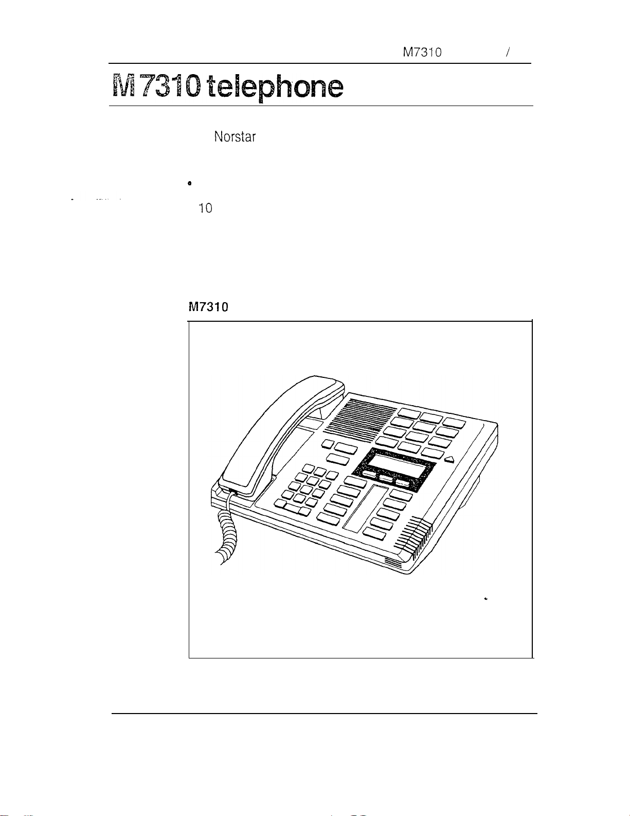
telephone 13
The
l
a two-line display
M7310 telephone offers the following features:
three display buttons
memory buttons with indicators
.
l
12 dual memory buttons without indicators
l
a shift button
l
Handsfree capability
telephone
Components
Page 66

14 M7324 telephone
The M7324 telephone offers the following features:
l
a two-line display
l
three display buttons
l
24 memory buttons with indicators
l
Handsfree capability
M7324 telephone
Components
Page 67

Mounting brackets 15
brackets
Mounting brackets support the Key Service Unit, Trunk
Module and Station Module on a wall. These brackets are
notched at the ends to aid in mounting the modules. Three
sizes of mounting bracket are available:
Size:
Full-size Key Service Unit
Half-size Trunk Module
Quarter-size Station Module
Mounting brackets
Mounting for:
Components
Page 68
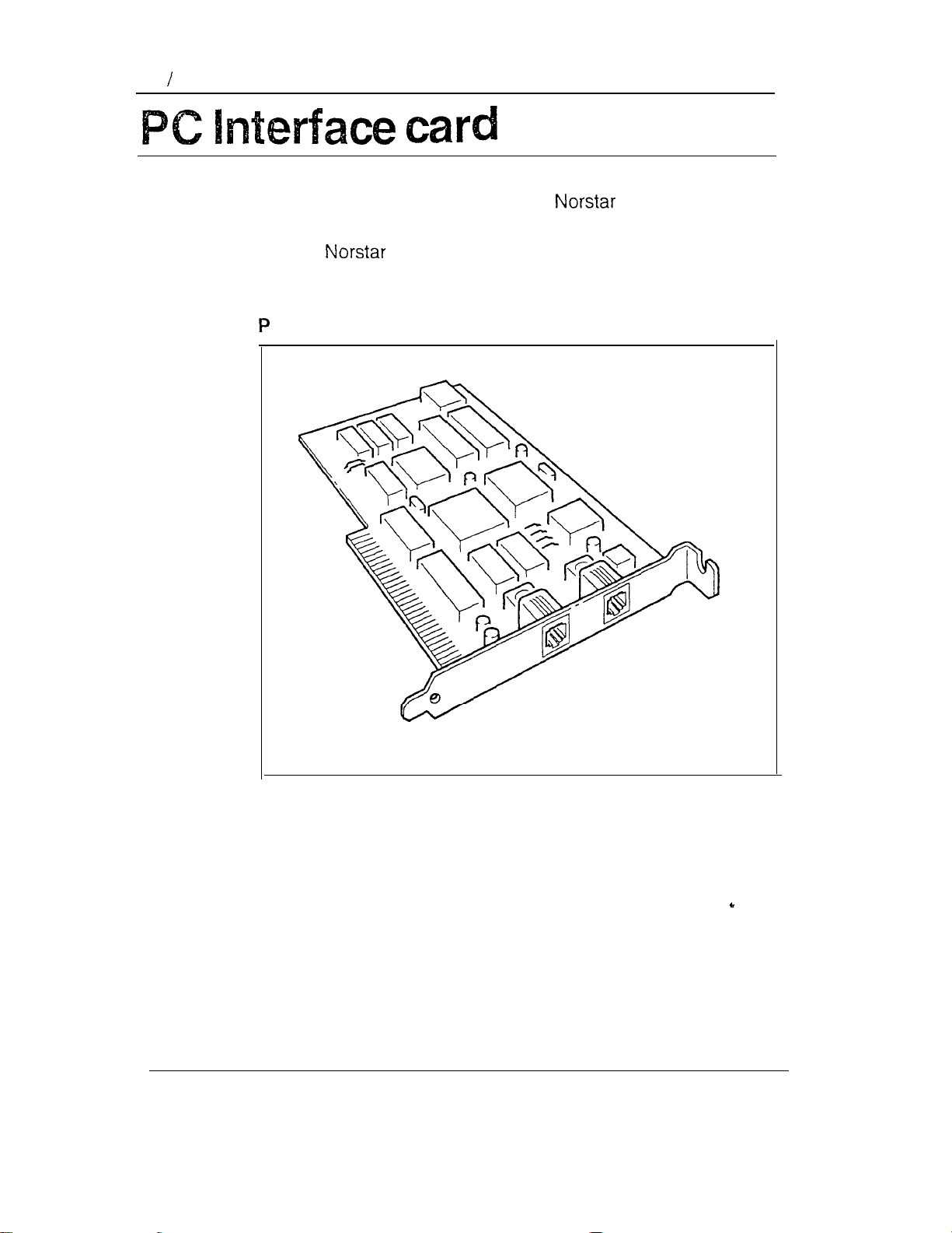
16 PC Interface card
The PC Interface card connects the system to a
Personal Computer (PC), This allows PC applications to run
with the system. The PC Interface card fits inside the
PC.
C Interface card
Components
Page 69

Power bar 17
The power bar provides four plug-in outlets for Trunk
Modules and/or Station Modules. It should be installed in the
lower half of the cable trough. If more modules are required
than can be plugged into one power bar, a second power bar
is required.
There are two types of power bars:
l
the 110 volt power bar which is approved
for use in North America
l
the 220 volt power bar for use outside North America
1 IO and 220 volt power bars
.
r
Components
Page 70

18 Station Auxiliary Power Supply
The
Station Auxiliary Power Supply (SAPS) is a
power transformer which plugs into a grounded 110 V ac
outlet. The SAPS provides regulated direct current for either
of two applications:
.
station loops longer than 305 m (1000 ft)
.
a Central Answering Position (CAP)
One SAPS can power two CAP modules, which do not have
to be connected to the same M7324 telephone.
Station Auxiliary Power Supply
Components
Page 71

Station Module 19
odule
The Station Module allows up to 16 additional
telephones to be connected to the Modular system. A
DS-30 cable connects each Station Module to the KSU.
Station Module
.
Components
Page 72

20 /Trunk Cartridge
The Trunk Cartridge, when inserted in a Trunk Module, adds
up to four external lines to the
Trunk Cartridges can be added to each Trunk Module.
There are three types of Trunk Cartridges:
l
the Loop Start Trunk Cartridge (4 lines)
l
the Trunk Cartridge (2 trunks)
l
the DID Trunk Cartridge
The Loop Start Trunk Cartridge supports regular external
lines. The Trunk Cartridge connects to a
private network. The DID Trunk Cartridge supports direct
inward dialing on incoming external lines.
(4
system. Up to three
trunks)
Loop Start, and DID Trunk Cartridges
Components
Page 73
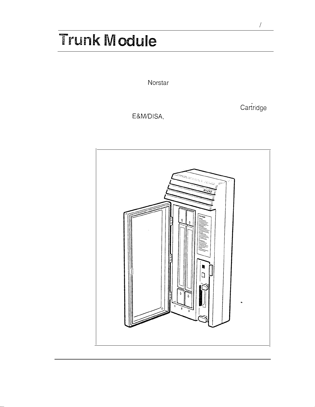
Trunk Module 21
The Trunk Module allows additional Trunk Cartridge
installation. This in turn allows more external lines to be
connected to the
system. The Trunk Module has
three slots in front for inserting Trunk Cartridges. Each Trunk
Module can add a maximum of 12 external lines (four external
lines per Trunk Cartridge). All three types of Trunk
(Loop Start, and DID) can be mixed in one Trunk
Module.
Trunk Module
Components
Page 74

Page 75

Hardware installation
l **ooeaoooo*ooooooooooooooooooooooo
Page 76

Regulations iii
Rights of the Telephone Company
If the system is determined to be causing harm to the
telephone network, the telephone company may discontinue
your service temporarily. If possible, the telephone company
will notify you in advance. If advance notice is not practical,
you will be notified as soon as possible. You will be given the
opportunity to correct the situation and you will be informed
of your right to file a complaint to the FCC. Your telephone
company may make changes in its facilities, equipment;
operations or procedures that could affect the proper
functioning of your system. If it does this, you will be notified
in advance to give you the opportunity to maintain
uninterrupted telephone service.
In the event of an equipment malfunction, all repairs will be
performed by Northern Telecom Inc. or by one of its
authorized dealers.
Address of repair facility
USA Canada
Northern Telecom Inc.
Product Service Center Customer Service Dept.
720
Nashville, TN
Attn. RA#
Drive
Use of a Music source
In accordance with U.S. Copyright Law, a license may be
required from the American Society of Composers, Authors
and Publishers, or similar organization if Radio or TV
broadcasts are transmitted through the Music On Hold or
Background Music features of this telecommunication
system.
Northern Telecom Inc. hereby disclaims any liability arising
out of the failure to obtain such a license.
Northern Telecom Canada Ltd.
914
12345
Albert Hudon
Hardware installation
Page 77

iv Regulations
This digital apparatus does not exceed the Class A limits for
radio noise emissions from digital apparatus set out in the
Radio interference Regulations of the Canadian Department
of Communications.
General installation warnings
WARNING
telephones must not be used as Off Premises
Station Sets (OPS).
equipment only. Connecting a telephone
directly to a CO line may result in equipment damage.
For OPS applications use the
Adapter
with single-line telephones.
Installers should also check the lightening protectors at
the cable entry point to the building with special attention
to the ground. Any problems should be reported to the
telephone company in writing.
should not leave the building, as it is not
protected.
telephones are for use with
Analog Terminal
telephone wiring
To avoid electrical shock, hazard to personnel, or
equipment damage, observe the following precautions
when installing telephone equipment:
l
Never install telephone wiring during a lightning storm.
l
Never install telephone jacks in wet locations unless
the jack is specifically designed for wet locations.
l
Never touch non-insulated. telephone wires or terminals
unless the telephone line has been disconnected at the
network interface.
l
Use caution when installing or modifying the telephone
lines.
Hardware installation
WARNING
Page 78

Radio Frequency Interference
WARNING
This equipment generates, uses, and can radiate radio
frequency energy. If not installed and used in
accordance with the instruction manual, it may cause
interference to radio communications. It has been tested
and found to comply with the limits for a Class
computing device pursuant to Subpart J of Part 15 of the
FCC Rules, which are designed to provide reasonable
protection against such interference when operated in a
commercial environment. Operation of this equipment in
a residential area is likely to cause interference, in which
case the user, at his own expense, will be required to
take whatever measures may be required to correct the
interference. Each Meridian
System is assigned an FCC Registration Number and a
Ringer Equivalence designation. The number and
designation are printed on the Key Service Unit (KSU)
label on the front of the unit inside the door.
Regulations i
A
Key Telephone
Registration
The Meridian Key Telephone System is registered
with the FCC based upon compliance with Part 68 of its
rules. Connection of the Meridian
System to the nationwide telecommunications network is
made through a standard network interface jack that you
can order from your telephone company. Jacks for this type
of customer-provided equipment will not be provided on
party lines or coin lines.
Key Telephone
Hardware installation
Page 79

ii Regulations
Ringer Equivalence Number (REN)
Hearing Aid Compatibility
The FCC Registration Label, on the inside of the door on the
front of the Key Service Unit (KSU), includes the Ringer
Equivalence Number (REN). This number shows the
electrical load that your
KSU requires from your
telephone line. If the KSU requires more electrical current
than your telephone company’s central office equipment can
provide, your telephones may not ring and you may have
difficulty dialing telephone numbers.
Call the telephone company to find out the total REN allowed
for your telephone line(s).
Meridian telephones are Hearing Aid compatible, as
defined in Section 68.316 of Part 68 FCC Rules.
Telephone Company Registration
It is usually not necessary to call the telephone company
with information on the equipment before connecting the
Meridian
(KSU) to the telephone network but, if the telephone
company requires this information, provide the following:
l
Telephone number(s) to which the Key Service Unit (KSU)
will be connected.
l
FCC Registration Number (on label affixed to KSU,
inside the door).
l
Ringer Equivalence Number (on label affixed to KSU,
inside the door).
l
USOC Jack
l
Service Order Code (SOC)
l
Facility Interface Code (FIC) for
Key Telephone System Key Service Unit
RJ-21 X for
service)
9.0 F
service)
Hardware installation
Page 80

Pre-installation
Checking the location
Checking the equipment
Unpacking the equipment 3
Installation
The KSU, TM and SM 4
Mounting the KSU, TM and SM
Installing an Expansion Cartridge 15
Installing a Trunk Cartridge 17
KSU and TM external lines 21
KSU and SM internal wiring 25
Contents v
Environment
Power source 2
3
Internal wiring 3
Tools 3
Recommended cable routing in cable troughs
Modular system hardware configuration
Reading the hardware chart 6
Hanging the modules on mounting brackets
11
External line cable and wiring material required
Connecting external lines 21
Station telephone cable and wiring material required:
25
Connecting KSU and SM internal wiring: 26
4
5
8
21
Connecting
Installing the Feature Cartridge 32
Emergency telephones 34
Connecting emergency telephones for a KSU
Connecting the emergency telephone for a TM
Testing the emergency telephones 36
Cables 29
34
35
Hardware installation
Page 81

vi Contents
Optional equipment 37
Installing an auxiliary ringer control 37
Installing an external music source 38
Installing an external paging system 39
Not-star telephones 42
Hearing aid compatibility 42
Installing M7324, M7310, M7208, and M7100
Telephones 42
Installing a wall-mounted telephone 43
Applying the button cap labels 47
Types of button caps 47
Typing the telephone numbers 48
default button assignments 49
Rules of default button assignment 49
Telephone button defaults 50
Power Bar installation 54
Installing a 110 V Power Bar 54
Installing a 220 V Power Bar
55
Power up system 56
Powering up 56
Automatic Telephone Relocation and telephone
replacement 58
Automatic Telephone Relocation 58
Relocating a telephone 58
Telephone replacement 59
Replacing
Replacing telephones of different types
Status of a telephone that was replaced
telephones of the same type
60
59
Hardware installation
Page 82

Checking the location
Check the location where the system modules, the
telephones, and auxiliary equipment are to be installed. This
includes making sure sufficient space is available to install
the components.
If a smooth surface is not available, cut a backboard large
enough to accommodate the system modules and the
distribution block. The system module physical dimensions
are listed in the Installation section of this chapter.
All modules must be mounted well above the floor to
Pre-installation 1
CAUTION
prevent water damage.
CAUTION
Mount the KSU vertically to avoid overheating.
Check also that the requirements for the environment and for
the power source are met.
Environment
Clean, dry, and well-ventilated
Temperature: to 50°C (32°F to 122°F)
Humidity: 5% to non-condensing
Location: at least 4 m (13.1 from equipment such as
copiers, electrical motors, and other equipment that can
produce electromagnetic, radio frequency, and
electrostatic interference.
Hardware installation
Page 83

2 Pre-installation
Note:
Installers should also check the lightning protectors
at the cable entry point to the building with special
attention to the grounding. Any problems should be
reported to the telephone company in writing.
buildings, as it is not lightning-protected.
Power source
Non-switched outlet
ac outlet located not more than 1.5 m (4.9 from the.
Key Service Unit (KSU). The actual distance from
KSU to the Power Bar may vary with additional Trunk
and Station Modules. Do not use an extension cord
between the KSU and the power bar.
For the V system
Dedicated 110 V ac nominal, Hz, 15 A minimum
service with third wire ground.
For the 220 V system
Dedicated 220-240 V ac nominal, Hz,
10 A minimum service with third wire ground.
Telephone wiring must not leave the
The ac outlet must be equipped with wire ground
to avoid electromagnetic interference.
Hardware installation
WARNING
Page 84

Checking the equipment
Check that you have the equipment required for
wiring
All new or existing wiring must meet the following
specifications:
one twisted or spiraled pair per telephone
dc loop resistance less than 59 ohms
cable length (0.5 mm or 24 AWG) not exceeding 305 m
(1000
A Station Auxiliary Power Supply can be used
to extend the length of the loop if the cable length
exceeds 305 m (1000 ft) but is less than 785 m
(2600 ft)
Pre-installation 3
no bridge taps.
screwdriver, diagonal cutters, pliers, connecting tool,
pencil, level (optional)
backboard, wooden, 19 mm inch) thick (when
recommended)
19 mm inch) screws suitable for surface mounting
bracket
38 mm (1 inch) screws for cable trough.
Unpacking the equipment
When unpacking the equipment, keep the boxes and inserts
in case any of the equipment has been damaged and must
be shipped back.
Hardware installation
Page 85

4 Installation
The MSU, TM and SM
The Key Service Unit (KSU), Trunk Modules (TM) and
Station Modules (SM) can be physically mounted in any
order. Allow suitable wall space for installing Trunk and
Station Modules for future expansion.
Note:
The doors of the KSU, TM and SM should not be
removed.
Recommended cable routing in cable troughs
Cable troughs beneath the KSU, TM and SM hold the
cables, the DS-30 cables, the power cord(s) and the
Power Bar (if required for a particular installation).
The cable troughs have been designed to keep the ac power
cords and ac Power Bar separate from the
and to allow ease of access after the installation. Place the
cabling in the two shelves as described in the following chart.
Cable placement
Upper shelf
All
only.
Place
cables and DS-30 cables
cables in the back.
cables
Lower shelf All power cords and the Power
Hardware installation
Place the DS-30 cables in the front.
Bar(s) only.
Page 86

Installation 5
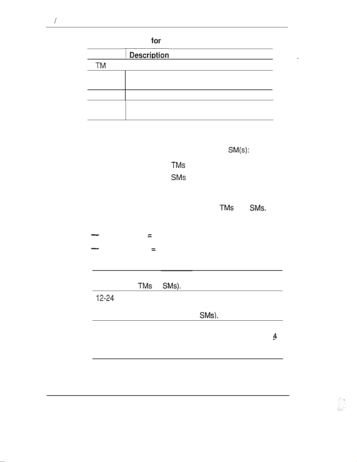
Modular system hardware configuration
This chart shows combinations of Trunk Modules (TM),
Trunk Cartridges (TC) and Station Modules (SM) for
expanding the Modular system. The first number represents
the number of physical external lines; the second number
represents the number of telephones. See the next page for
how to read the chart.
Possible line and station configurations
SM SM SM SM SM
TM TC 0 1 2 3 4 5
00 8-24 8-40 8-56 8-72 8-88 8-104
11
2 16-24 16-40
14 64-24 64-40
15
6 16
17 76-241
18
Note:
Number of physical lines shown is for Loop Start and DID Trunk Cartridges
only. Trunk Cartridges provide half the number of
12-24 12-40 12-56 12-72 12-88 12-104
16-72 16-88 16-l 04
68-24 68-40
80-24
.
6
8-120
Hardware installation
Page 87
6 Installation
Key to the terms the hardware chart
Term
Number of Trunk Modules
TC
SM
8-24
Number of Trunk Cartridges (maximum of 3
for each TM)
Number of Station Modules
The KSU has a maximum of 8 lines and 24
telephones.
Reading the hardware chart
To find the maximum number of lines and telephones for a
particular configuration of KSU, TM(s) and
1.
Find the number of in the left column.
2.
3.
Find the number of in the top row.
Read across to the right from the TM column and down
from the SM row. A pair of numbers indicates lines and
telephones for that combination of
For each pair of numbers on the chart:
left number maximum number of lines.
and
right number maximum number of telephones.
Examples:
8-24
12-40
Hardware installation
=
8 lines and 24 telephones (KSU without
or
=
12 lines and 24 telephones (KSU lines and
telephones, plus one TM and one TC with 4
more lines, and no
=
12 lines and 40 telephones (KSU lines and
telephones, plus one TM and one TC with
more lines, and one SM with 16
telephones).
more
Page 88
Installation 7
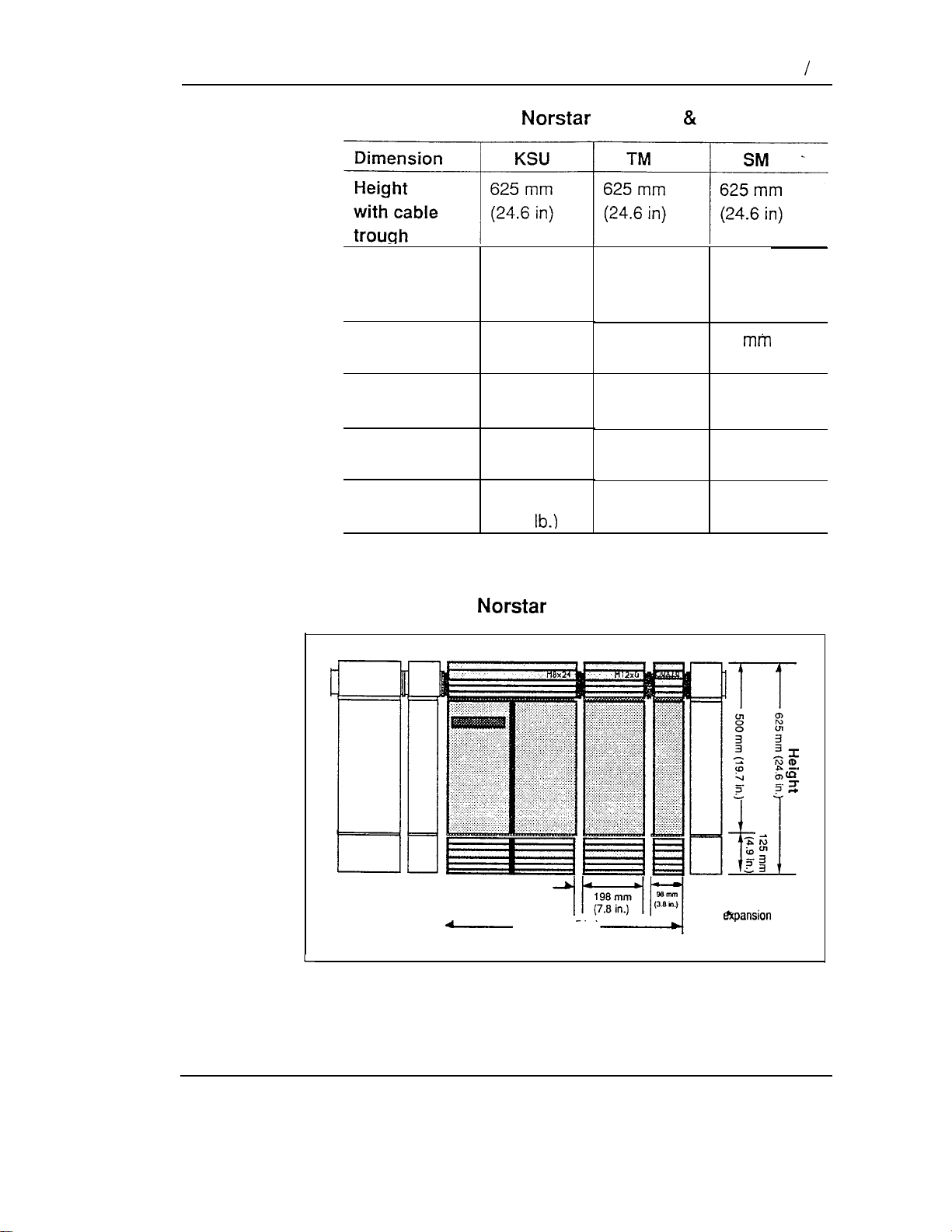
Physical dimensions of KSU, TM SM
Height
without cable
500
(19.7
mm
in)
500 mm
(19.7 in) (19.7 in)
trough
Width
Depth
Clearance
(front)
Weight
395
mm
(15.5 in)
171 mm
(6.7 in)
346 mm
(13.6 in)
7.5
Kg
(16.6
4.3
198 mm
(7.8 in) (3.8 in)
171 mm 171 mm
(6.7 in)
346 mm 245 mm
(13.6 in) (9.6 in)
Kg
(9.5 lb.)
Dimensions of the Modular System
r
KSU TM SM
500 mm
98
(6.7 in)
2.4
Kg
(5.3 lb.)
If possible, leave
enough room for
future expansion
Note:
395 mm(15.5 in.) If possible, leave
t
696 mm (27.5 in.)
Widths
enough room for
future
Modules may be installed in any order. If possible,
leave enough room for expansion as indicated.
Hardware installation
Page 89

8 Installation
Hanging the modules on mounting brackets
Leave about 150 mm (6 inches) of space above the screw
holes of the mounting bracket. This allows room to lift the
KSU, TM and SM ON and OFF the bracket and provides
space for venting the heat from the modules.
Bottom
Ensure there is at least 100 mm (4 inches) of space between
the bottom of the cable trough and the floor, or any object
that may block the flow of air from the bottom, for cooling.
Sides
Leave enough room to be able to open the doors of the
modules and to run cabling out to the side.
Between modules
The space between two modules hung on the mounting
brackets is approximately 3 mm
Note:
See the illustration showing dimensions of the
Modular system for additional module
clearance requirements.
inch).
Hardware installation
Page 90

Key Service Unit (KSU)
Installation 9
LED
CO Lines 50-pin connector
Feature cartridge (2 parts)
Cable clips
Stations connector
Expansion cartridge
cartridge shown)
Half-size
Cable trough
Trunk Module (TM)
Slot for Trunk cartridge
(face plate removed)
Protective faceplates
covering unused slots
LED
DS-30 port
Cable clip
50-pin connector
Trunk cartridge
Half-size
Cable trough
Hardware installation
Page 91

IO
Station Module (SM)
LED
DS-30 port
Cable clips
connector
Cable clips
Quarter-size
Cable trough
Hardware installation
Page 92

Mounting the KSU, TM and
Installation 1
1
-1.
Position metal mounting bracket(s): Fasten the
bracket to the wall using four 19 mm in) screws.
Hint:
installing the KSU mounting bracket
Use a level and draw a pencil line to align the
KSU. This will be useful to line up Trunk and
Station Modules if they are part of the system.
Hardware installation
Page 93

12 installation
2.
Slide the KSU, TM or SM down onto the mounting
brackets. Line up with the notches on either side of the
bracket as you slide the KSU onto the
mounting bracket(s). This facilitates accurate hanging.
Hanging the KSU
3.
Slide the cable trough(s) up under the appropriate
module(s). The KSU requires two cable troughs.
Hardware installation
Page 94

4.
Open each cable trough door and allow the door to
swing down.
Installation 13
5.
Use 38 mm (1 in) screws to fasten each cable trough
to the wall as shown in the cable trough installation
illustration. Each cable trough requires two screws
through the holes provided in the lower tray of the cable
trough.
Installing the cable troughs
Hardware installation
Page 95

14 Installation
KSU, TM and SM installed
Key Service Unit (KSU)
Feature
cartridge
Expansion
cartridge
shown)
Note:
Trunk
The illustration shows a KSU, TM and SM
Start
e
without the doors for clarity. The doors should
not be removed during installation or operation.
Also shown are the Feature, Expansion and
Trunk Cartridges which are installed later.
6.
Close the door(s) of the cable trough(s).
Cable trough Cable trough
(l/4-size)
Station
Module
7.
Do
Hardware installation
not
connect power at this point.
Page 96

installation 15
an Expansion Cartridge
Installation for Two-port and Six-port Expansion Cartridges
follow the same procedure. (Refer to the Port Numbering
section of the Technical data module for changes to default
DN length caused by installing an Expansion Cartridge.)
CAUTION
Do not touch the printed circuit board. This is an
electrostatic-sensitive device.
Make sure that the KSU power is OFF before installing
1.
or removing an Expansion Cartridge.
2.
Remove the cover of the Expansion Cartridge slot in
the KSU. Use a screwdriver at the bottom of the
cartridge slot cover, as indicated by the icon, to help
detach the cartridge slot cover from the slot.
Removing the cartridge slot cover
Hardware installation
Page 97

16 installation
Make sure you are wearing a grounding strap when
handling any cartridge.
While holding the latches open, insert the Expansion
Cartridge in the appropriate slot as shown and close
the latches at the same time to align the cartridge
properly.
installing a Six-port Expansion Cartridge
Hardware installation
Page 98

Installation 17
a Trunk Cartridge
The types of Trunk Cartridges available are
Loop Start Trunk Cartridge (with or without disconnect
supervision)
Trunk Cartridge
DID Trunk Cartridge
The procedures for installing the different types of Trunk
Cartridges are identical. For wiring charts, see the Technical
data chapter.
Programming Trunk Mode for Trunk Cartridges
It is important, in Configuration programming, to set the
Trunk Mode value for Loop Start Trunk Cartridges correctly.
All lines on a Trunk Cartridge will be affected by changing
the Trunk Mode setting on any one line. See the
Configuration chapter to set Trunk Mode.
Hardware installation
Page 99

18 Installation
All three types of Trunk Cartridges can be installed in one
Trunk Module if required for a particular installation. When
mixing Trunk Cartridges, use a separate distribution block for
each type of Trunk Cartridge. This ensures that the proper
(Loop Start and DID) and
interfaces are obtained (see the examples in
the Technical data chapter on how to read the
and the DID wiring charts).
CAUTION
Do not touch the printed circuit board. This is an
electrostatic-sensitive device.
1.
Make sure that the Trunk Module power is OFF before
installing or removing a Trunk Cartridge.
2.
Remove the appropriate cartridge slot cover of an
unused Trunk Cartridge (TC) slot on the TM. Use a
screwdriver at the bottom of the cartridge slot cover, as
indicated by the icon, to detach the cartridge slot cover
from a Trunk Cartridge (TC) slot.
The Trunk Cartridges (TC) are installed starting
from the left slot to the right slot.
Hardware installation
Page 100

Removing the cartridge slot cover
Installation 19
Hardware installation
 Loading...