

Page 1
Norsat NewsLink
Operator’s Manual
June 2003
Page 2

Page ii
Please read this entire guide
Veuillez lire entièrement ce guide
Bitte das gesamte Handbuch durchlesen
Sírvase leer completamente la presente guía
Si prega di leggere completamente questa guida
Important
Please read this entire guide before you install or operate this product. Give particular attention
to all safety statements.
Important
Veuillez lire entièrem ent ce gui de avant d ’installer ou d’utili ser ce pro duit. Prêt ez une at tention
particulière à toutes les règles de sécurité.
Zu Beachten
Bitte lesen Sie vor Aufstellen oder Inbetriebnahme des Gerätes dieses Handbuch in seiner
Gesamtheit durch. Achten Sie dabei besonders auf die Sicherheitshinweise.
Importante
Sírvase leer la presente guía antes de instalar o emplear este producto. Preste especial
atención a todos los avisos de seguridad.
Norsat NewsLink 099-20003-01OM
Norsat
Page 3
Notices
Tr ademark Acknowledgments
Norsat is a registered trademark of Norsat International, Inc.
The Norsat logo is a registered trademark of Norsat International, Inc.
All other trademarks shown are trademarks of their respective owners.
Disclaimer
Norsat International, Inc. assumes no responsibility for errors or omissions that may appear in
this publication. Norsat reserves the right to change this publication at any time without notice.
Copyright
©2003 Norsat International, Inc. All rights reserved. Printed in Canada.
Information in this pub lication is subject to c hange without notice. No part of th is publication
may be reproduced o r transmitted in any form, by photo copy, microfilm, xerography, or any
other means, or in corporated into any information retrieval syste m, electronic o r mechanical,
for any purpose, without the express permission of Norsat International, Inc.
Page iii
Revision History
Date Nature of Revision Release
January 2003 Initial Draft. 1.0
February 2003 Update with release changes. 1.1
June 2003 R1 Release. 1.2.2
Norsat NewsLink 099-20003-01OM
Norsat
Page 4

Page iv
Norsat NewsLink 099-20003-01OM
Norsat
Page 5

Contents
Notices iii
Trademark Acknowledgments iii
Disclaimer iii
Copyright iii
Revision History iii
Preface ix
Text Conventions ix
Definitions, Abbreviations and Acronyms x
Protocols and Standards xii
CHAPTER 1 Safety Precautions 1
CHAPTER 2 Norsat NewsLink Overview 3
Features 3
System Operation 3
CHAPTER 3 Norsat NewsLink Cases 7
CHAPTER 4 Antenna/RF Unit 9
Antenna/RF Unit Cases 9
Antenna 11
Transceiver 11
Peripherals 11
Compass 11
Inclinometer 12
Level 12
Norsat NewsLink 099-20003-01OM Page v
Page 6

Page vi
Interface/Indicator Unit 12
Ku-L Block Down-converter 12
CHAPTER 5 Baseband/IF Unit 13
Baseband/IF Unit Case 13
Baseband/IF Unit Interfaces 14
IFL Interface Panel 14
Test Interface Panel 15
Power Inte rface Panel 16
Auxiliary Interface Panel 16
Audio Monitor Interface Panel 17
Analog Audio In Interface Panel 17
Video In Interface Panel 17
Digital Sig nal In Interface Panel 17
L-Band Interface Panel 17
GPS Receiver Interface Panel 18
Baseband/IF Unit Functionality 18
Transmit and Output Power Settings 18
Maintenance and Indicati on 18
Transmission Frequency Setting 18
Audio & Video Encoding 19
Channel Coding and Modulation 19
Upconversion, Frequency Level Control 19
Reception of DVB-S/MPEG-2 TS 19
Encoded Video Display 19
Antenna Pointing Calculations 19
Spectrum Analyzer 20
CHAPTER 6 Norsat NewsLink Deployment 21
Deploying the Antenna/RF Unit 21
Opening the RF Unit Cases 22
Deploying the Antenna 23
Deploying the Baseband/IF Unit 32
Opening the Baseband/IF Unit Case 33
Baseband/IF Unit Cable Connections 33
Antenna and Baseband Unit Interconnections 33
Interfacility Link 34
Interconnection 34
Connecting Peripherals to the Baseband/IF Unit 36
Powering Up the Baseband/IF Unit 36
CHAPTER 7 Norsat NewsLink Configuration 37
Setup Procedure Overview 37
Step 1: Configure System Settings 37
Step 2: Antenna Alignment 38
Step 3: Transmitter Control 38
Norsat NewsLink GUI 39
System Settings 40
Norsat NewsLink 099-20003-01OM
Norsat
Page 7

Satellite Information 40
Transmission Profiles 42
Transmit Frequency Presets 47
Transmit Power Quick Keys 49
LNB Selection 50
Antenna Alignment 51
Transmitter Control 59
Keyboard Shortcuts 62
Transmitter Status 63
CHAPTER 8 Storing the Norsat NewsLink 71
Storing the Baseband/IF Unit 71
Powering Down the Baseband/IF Unit 71
Closing the IF Unit Case 71
Disconnecting Peripherals from the Baseband Unit 71
Disconnecting the Antenna and Baseband Units 72
Storing the Antenna/RF Unit 72
CHAPTER 9 Troubleshooting 77
Page vii
General Troubleshooting Tips 77
Transmission Problems 77
Video Problems 78
Two-way Communication Problems 79
Persistent Problems 79
Appendix A 81
NewsLink GUI Status Indicators 81
Video Lock 81
Encoder Activity 81
Transmitter and Upconverter Current 82
SSPA Current 82
SSPA Temperature 83
PLL Lock 83
Tx Power 84
Tx Downconverter Current 84
Video Bitrate 85
Audio Bitrate 85
Transmit Loopback Quality 85
Downconverter & LNB Current Consumption 86
Rx Signal Quality 86
Appendix B 89
Compass Calibration 89
Norsat NewsLink 099-20003-01OM
Norsat
Page 8

Page viii
Norsat NewsLink 099-20003-01OM
Norsat
Page 9

Text Conventions
Preface
• Text appearing in Courier font indicates charac ters to be t yped in; e.g.
type Shell indicates that the word “Shell” mus t be entered exactly as it
appears, with the first letter capitalized.
• Text appearing in Bookman Old Style font indica tes a direc tory path or
filename; e.g. c:\Program Files.
• Text enclosed in angle brackets indi cates a field entry; e.g. <PID> indi-
cates that a PID value must be entered.
• Text appearing in
indicates either a bu tton that m us t be c li cked, a key that must be presse d
or a particular screen; e.g. B
SMALL CAPS and Century Gothic font in an instruction
UTTON indicates a button that must be clicked.
Norsat NewsLink 099-20003-01OM Page ix
Page 10

Page x
Definitions, Abbreviations and Acronyms
A Ampheres
AC Alternating Current
BER Bit Error Rate
CW Continuous Wave
dB Decibels
dBi Decibels Relative to an Isotropic Radiator
dBm Decibels Relative to 1 Milliwatt
dBW Decibels Relative to 1 Watt
DC Direct Current
DTS Decoding Time Stamp
DVB Digital Video Broadcast
DVB-S DVB over Sa tellite
EIRP Equivalent Isotropic Radiated Power
ETSI European Telecommunications Standards Institute
FCC Federal Communications Commission
FEC Forward Error Correction
GHz Giga-Hertz
GOP Group of Pictures
GPS Global Posi tioning System
GUI Graphical User Interface
IF Intermediate Frequency
IFL Interfacility Link
IP Internet Protocol
IRD Integrated Receiver Decoder
Ka 18 GHz to 36 GHz Frequency Band
LED Light Emitting Diode
LNB Low Noise Block Downconverter
Mbps Megabits Per Second
MHz Mega-Hertz
MPEG-2 Moving Pictures Expert Group
NTSC National Television Standards Committee
OMT Ortho Mode Transducer
PAL Phase Alternation Line
PID Packet Identifier
PLLs Phase-Locked Loops
QEF Quasi Error Free
QPSK Quadrature Phase Shift Keying
RF Radio Freq uen cy
Rx Receive / Receiver
Norsat NewsLink 099-20003-01OM
Norsat
Page 11

SDI Synchronous Digital Interface
SES Société Européenne Des Satellites
SNG Satellite News Gathering
SSPA Solid State Power Amplifier
TS Transport Stream
Tx Transmit / Transmitter
USB Universa l Serial Bus
WWatt
Page xi
Norsat NewsLink 099-20003-01OM
Norsat
Page 12

Page xii
Protocols and Standards
10BaseT IEEE 802.3 10Base-T Standard
100BaseT IEEE 802.3 100Base-T Standard
ANSI American National Standards Institute, web.ansi.org
ARP Address Resolution Pro toc ol
ASI Asynchronous Serial Interface
DAVIC Digital Audio-Visual Council, www.davic.org
DSM-CC ISO/IEC 13818-6
DVB Digital Video Broadcast Project, www.dvb.org
DVB-S ETS 300 421 Digital Satellite Transmission Systems
IEEE Institute of Electrical and Electronic Engineers,
ISO/IEC International Organization for Standardization, www.iso.ch
IP RFC 791 Internet Protocol, Version 4 (IPv4)
IPSec RFC 2401, Security Architecture for the Internet Protocol
MIB Management Information Base
MMDS DVB (M)MDS ETS 300 748 & ETS 300 749 Digital (Micro-
MPEG-2 Moving Picture Experts Group: Generic Coding of Moving
ODBC Open DataBase Connectivity
PPP RFC 1661, Point-to-Point Protocol
PPTP Point-to-Point Tunnelling Prot ocol
RADIUS RFC 2138, Remote Authentication Dial In User Service
RIPv2 Routing Information Protocol, Version 2
SMPTE 325M SMPTE 325M-1999 Opportunistic Data Broadcast Flow
SNMP RFC 1905, Protocol Operations for Version 2 of the Simple
SQL ISO/IEC 9075:1992, Information Technology Database Lan-
TCP RFC 793, Transmission Control Protocol
TCP/IP Transmission Control Protocol/Internet Protocol
www.ieee.org
wave) Multipoint Distribution Systems (MDS)
Pictures and Associated Audio Information ISO/IEC DIS
13818
Control; RP 206-1999 Opportunistic Data Flow Control
Using Ethernet as a Control Channel in an MPEG-2 Transport Emissions Multiplex
Network Management Protocol (SNMPv2)
guages - SQL & ANSI X3.135-1992, Database Language
SQL
Norsat NewsLink 099-20003-01OM
Norsat
Page 13
CHAPTER 1 Safety
Precautions
IMPORTANT All safety precautions should be read and understood pr ior to d eploying
the Norsat NewsLink.
W
ARNING FCC INFORMATION FOR UNINTENTIONAL RADIATOR PORTIONS AS PER FCC
15.19, 15.21
“This equipment has been tested and found to comply with the limits for a
Class A digital device, pur suant t o Pa rt 1 5 of th e F CC Rul es. T hes e lim its are
designed to provided reasonable protection against harmful interference
when the equipment is operated in a commercial environment. This equipment generates, uses, and can radiate radio frequency energy and, if not
installed and used in accordance with the instruction manual, may cause
harmful interference t o radio co mmunicati ons. Opera tion of this equipme nt in
a residential area is likely to cause harmful interference in which case the user
will be required to correct the interference at his own expense.”
AND 15.105
W
ARNING Changes or modifications not expressly approved by Norsat International
could void the user’s authority to operate the equipment.
W
ARNING FCC RF EXPOSURE INFORMATION
To satisfy FCC RF exposure requi rements for mobile tra nsmitting device s, a
separation distance of 2.5 meters or more should be maintained between the
!
W
ARNING FCC FREQUENCY COORDINATION AS PER FCC 25.203(C), 25.251 AND 101.103
W
ARNING MICROWAVE RADIATION: HAZARDS CAUSED BY ELECTROMAGNETIC FIELDS
Norsat NewsLink 099-20003-01OM Page 1
antenna of this device and pers ons during device op eration. To ensure compliance, operations at closer than this distance is not recommended.
To satisfy FCC frequency coordination requirements, the user must ensure
that they co-ordinate propo sed frequen cy and power usage wit h other terrestrial and satellite users prior to transmission.
When in operation, i.e. power on, the area directly in front of the Norsat
NewsLink antenna dish must be considered an Area of Restricted Occupancy.
Limit human exposure time to this area when the Norsat NewsLink is in
operation.
Page 14
Page 2
Never place any part of the body between the antenna dish an d the antenna
feed horn assembly, or in line with the direction of the antenna transmission
path when the Norsat NewsLink is in operation.
Locate the terminal as far as practical from ungrounded metal.
G
ROUNDING
When used within urban areas, it is suggested that the Norsat NewsLink be
earthed via a grounding electrode in strict accordance with National and Local
electrical codes.
C
AUTION Wherever possible, operate the Norsat NewsLink with the grounding
conductor connected.
W
ARNING HIGH VOLTAGE AND HIGH CURRENT POWER PRESENT
During periods of rain or strong wind, as well as in wet conditions, be
especially attentive to the connectors and power cords of the Norsat
!
NewsLink. Be on the look out for an y el ectr ic al dang ers c aus ed by the Nor sa t
NewsLink power coming in contact with water. Disconnect the Norsat
NewsLink from the power source prior to moving it out of danger spots.
Immediately disconnect the Norsat NewsLink from the power source when
unit power malfunction is suspected.
C
AUTION The Baseband Unit together with all its parts, including the bulkhead
connectors, are not rated as water resistant and therefore must always be
sheltered from rain or any othe r s ourc e of wate r. Failure to do so can result in
Norsat NewsLink sy stem damag e, and/o r se rious user inju ry due to elec trical
hazards.
Norsat NewsLink 099-20003-01OM
Norsat
Page 15

CHAPTER 2 Norsat
NewsLink
Overview
The Norsat NewsLink is a portable sat ellite terminal th at provides broadc ast
quality MPEG-2 vid eo transmiss ion, communic ating with a centr al teleport or
HUB station. Its design allows it to be carried by two p eople, with an in field
deployment and setup time by a camera operator of less than 15 minutes.
Features
System Operation
The Norsat NewsLink:
• Allows for quick on-location arrival and setup time, in order to begin
broadcasting for major int ernationa l news events before a typic al flyaway
system could arrive and be operational
• Provides more flexibility to the on-site news team as to the location of
where the uplink s ystem can b e operated, as opposed to traditiona l flyaway systems which require a fixed major center for the duration of the
transmission
• Allows for quic k tran sp ort due to i ts por tability, thus enabling ne ws te ams
to easily cover sma ll live international events or reach a l ocation that is
typically not considered by conventional flyaway operations
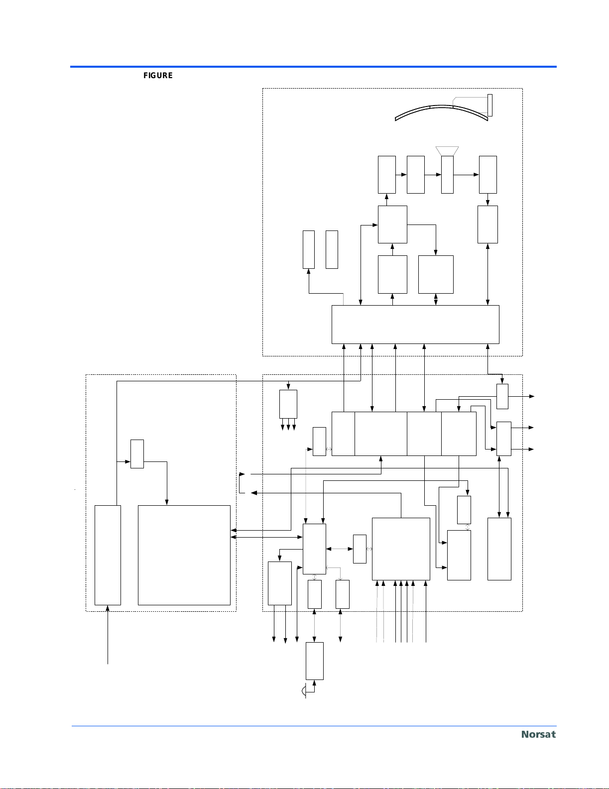
A block diagram of the Norsat NewsLink is given in Figure 1 on page 4.
Norsat NewsLink 099-20003-01OM Page 3
Page 16
Page 4
FIGURE 1. Norsat NewsLink Block Diagram.
with
superstructure
Segmented Antenna
Filter
Bandpass
Compass
Inclinometer
12V DC
Antenna/RF Unit
DC-DC
USB-
70 MHz in
DC-DC
from external modulator
Serial
SSPA DC/MAC
SSPA DC
SSPA MAC
Signal Strength
70-L
DC-DC/uP/Ref
Upconverter
Isolator
25 W
Ku SSPA
L-Ku
>2 W
Transmitter
Indicator
Inerface/
Tx IF/DC/REF
OMT / Feed
Ku-L
Block DNC
Box
Txb IF/DC/REF
L-25
L-25
(Tx signal)
Downconverter
TRF
LNB
(Internal
Reference)
Rx IF/DC
Rx IF/DC
Splitter
(Rx beacon )
Downconverter
switch
to External
(back panel)
Demodulator
(front panel)
to external IRD
Rx and Tx monitor
24V DC
MAC
70 MHz
Monitor
USB Ethernet
AC -DC Power Supply
Power Supply /Notebook Unit
AC 110V/220V In
Rugged Notebook
Baseband/IF Unit
MAC
#2#5
#7
USB Hub
#1
#6
#4
Audio
Processor
USB-
Serial
GPS
Receiver
USB Input
Audio 1 & 2 Mon
Audio 3 & 4 Mon
USB-
To external Modem
USB-
Serial
Serial
MAC
#3 #8
&
Encoder
MPEG-2
DVB-S Modulator
SDI
Composite Video
Digital A udio
Bal. Audio 1,2,3,4
Unbal. Au di o 1,2,3,4
USB-
Parallel
Module
Analyzer
Spectrum
MAC
Rx or Tx monitor
DVB-S Receiver
Norsat NewsLink 099-20003-01OM
Norsat
Page 17

Page 5
Satellite infor mation may be setup prior to on-location arrival, in addition to
Transmission Profile(s) that detail the sy stem settings, includ ing the creation
of a transport stream and setup of video and audio PIDs.
The Norsat NewsLink is enclosed in thre e cases; the Base band/IF case and
the two Antenna/RF case s: RF and Antenn a Unit case, Model 32 00-RF, and
Accessories case , Model 3200-AC. Once the news team is on location, the
antenna is removed from the case and assembled; the Baseband unit may be
removed from the carrying case, or may be in a shock mounted chassis. After
the antenna is assembled, it is connected to the Baseband/IF unit. The Norsat
NewsLink is now ready to be configured.
The antenna must be al igned to the proper elev ation, azimuth and polar ization for the desired satellite transponder. Using the Norsat NewsLink graphical
user interface (GUI), the user selects the desired satellite and polarization
from which the global position ing system (GPS) deter mines the curre nt location of the antenna. Once this is obtained the proper azimuth, polarization and
elevation are calculated.
The polarization is set using the indicator located on the fe ed assembly. A
compass located on th e base of the antenna indicate s the current azimuth,
and an inclinometer lo cated on the back of the d ish indicat es the curre nt elevation. The azimuth and elevation values are set to the values indicated in the
Norsat NewsLink GUI. Then, while watching the signal strength meter, the
antenna is fine tuned in order to obtain an optima l si gna l stren gth . In addition ,
the Norsat NewsLink G UI contains a spectrum analyze r, which can also be
used to align the antenna and verify that locked onto correct satellite.
After the antenna is pr ope rly al ign ed, the ca mera and external equipment are
then connected to the Baseband unit.
N
OTE This step is done after an tenna align ment as the Base band/IF uni t may need
to be moved.
Using the Norsat NewsLin k GUI, the previously configured Transmiss ion Pro-
file is selected.
The satellite operator is now called to obtain approval for transmis sion. The
user indicates to the satellite operato r the selected sate llite and transponder
(frequency and polariza tion) they wish to transmit on. When author ization is
given by the satell ite operator, the news crew brings up a continuous wave
(CW) signal at the requested power setting. This setting will be adjusted to the
proper levels a s indicated by the satellite operator. The polarization will then
be checked usin g a cross-pol signal. The satellite opera tor will then request
that the news crew turns modulation ON at low power. The power level is
gradually increased unti l t he m axi mu m power level is reached. O nce prop er ly
set, the satellite oper ator will give the news team auth orizati on to beg in news
transmission.
Norsat NewsLink 099-20003-01OM
Norsat
Page 18

Page 6
Norsat NewsLink 099-20003-01OM
Norsat
Page 19

CHAPTER 3 Norsat
NewsLink
Cases
The cases that house the Norsat NewsLink Antenna/RF and Baseband/IF
units are weatherproof, and there should be no water penetration when all
winglocks are properly secured.
The cases will provide sh ock and vibration protection du ring storage, transport and, in the case of the Baseband/IF unit, operation. However, care
should be taken when handling the cases in consideration of the enclosed
electronic equipment of the Norsat NewsLink.
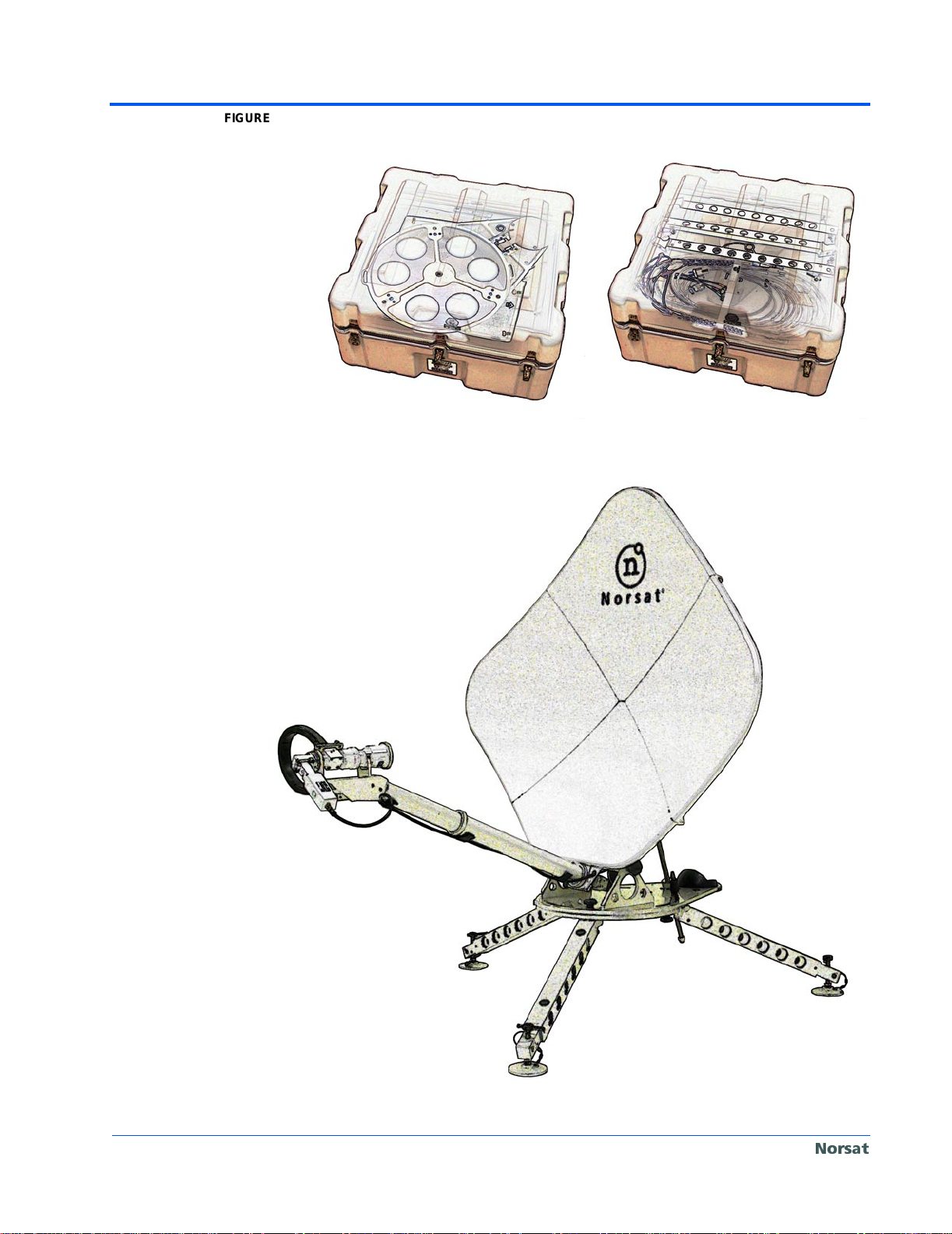
The Antenna/RF unit i s stored in two case s, the RF and Antenna Unit case,
Model 3200-RF, and the Accessorie s case, Mo del 3200-AC; re fer to Figure 2
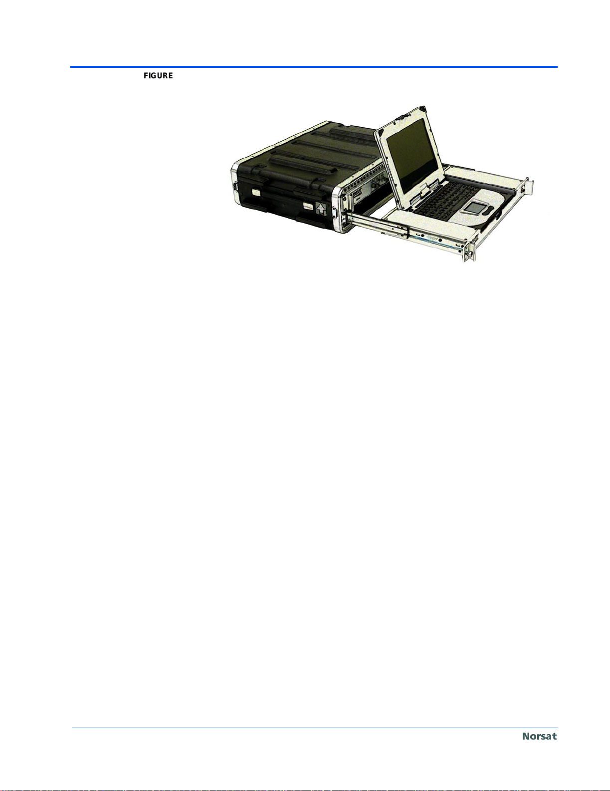
on page 8. The Baseb and/IF unit is st ored in one case; r efer to Figure 3 on
page 8.
The Antenna/RF cases are equipped with a press ure relief valve that equa lizes the pressure inside and outside the case. This relief is provided automatically should the pressure difference become too large, thus preventing the
case from exploding due to extreme differences in atmospheric pressure.
Alternatively, the case may be under a vac uum and hard to open . The valve
can also be depressed by the user to manually equalize the pressure.
N
OTE This procedure i s necessary befor e opening a case to e nsure that unlo cking
the latches on the c ase is bo th safe and easy; refer to “ Opening th e RF Unit
Case” on page 22 for instructions.
Norsat NewsLink 099-20003-01OM Page 7
Page 20
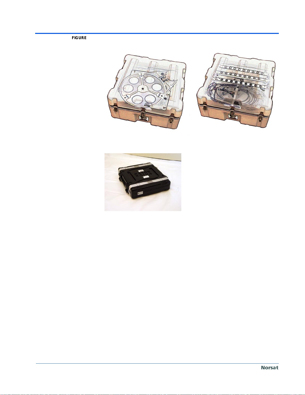
Page 8
FIGURE 2. Antenna/RF Unit Cases.
FIGURE 3. Baseband/IF Unit.
Norsat NewsLink 099-20003-01OM
Norsat
Page 21

CHAPTER 4 Antenna/RF
Unit
The Antenna/RF unit is comprised of the following components:
• Antenna
• Transceiver
• Peripherals
A diagram of the Antenna/RF unit cases are given in the next section, followed by descriptions and specif ications for each of the above liste d components.
Antenna/RF Unit Cases
The Antenna/RF unit contains the components that comprise the antenna.
Figure 4 on page 10 shows the disassembled antenna components when
stored, and Figure 5 on page 10 shows the assembled antenna.
Norsat NewsLink 099-20003-01OM Page 9
Page 22
Page 10
FIGURE 4. Antenna/RF Unit Stored. RF and Antenna Unit case, Model 3200-RF, on
the left and Accessories case, Model 3200-AC, on the right.
FIGURE 5. Antenna/RF Unit Deployed.
Norsat NewsLink 099-20003-01OM
Norsat
Page 23

Antenna
Transceiver
Page 11
The antenna consists of the di sh reflector, feed horn, OMT, flex waveguides,
boom arm with built in rigid waveguide and mechanical support structure. The
mechanical support structure positions and points the antenna reflector in
order to aim the antenna beam at the required satellite.
The Transceiver consists of block upconver ter/transmitter, a 15 W or 25 W
solid state power amplifier (SSPA) and a low-noise block (LNB) downconverter. The block upconverter converts the incom ing L-band (950- 1450 MHz)
signal to Ku-band (14 -14.5 GHz). That signal is then amplified by the 15 W or
25 W SSPA, and fed through the antenna. Thus, after converting to dBW, the
system provides a maximum effective isotropic radiated power (EIRP) of 53
dBW for the 15 W SSPA and 55.5 dBW for the 25 W SSPA.
The LNB then down-converts the down-linked Ku-band signal:
• A: 11.7 - 12.2 GHz
• B: 12.25 - 12.75 GHz
• C: 10.95 - 11.7 GHz
to an L-band signal:
• A: 0.95 - 1.45 GHz
• B: 0.95 - 1.45 GHz
• C: 0.95 - 1.7 GHz
Peripherals
The peripherals aid in antenna pointing and include the following:
• Compass: used for azimuth settings
• Inclinometer: used for elevation settings
• Level: used to ensure antenna is level
• Interface/Indicator: interface for IFL connections, indicates when the
transmitter is on and indicates the receive signal strength
• Ku-L Block Down-converter
Compass
The fluxgate compass has a di gital display with an accuracy of degree.
The compass is mounted on the base of the antenna in order to accurately
indicate the azimuth of the antenna beam. T he compass is powered by 12 V
supplied from the Bas eband/IF unit. It is connected to the Interface Indica tor
unit by a flying lead with a multi-pin connector.
As with all fluxgate compass es, best perfor mance occur s when the compass
is level and ther e is no ferrous metal ob jects a round. To compensate for both
hard and soft magnetic inter ference, the compass should b e calibrated. The
compass is calibrated at the factor y, however, it is beneficial to re-calibrate it
Norsat NewsLink 099-20003-01OM
1±
Norsat
Page 24

Page 12
Inclinometer
at new locations or if the ma gnetic environment/interface cha nges. Refer to
“Compass Calibration” on page 89 for instructions on re-calibration.
The inclinometer has a digital display with an accuracy greater than 0.5
degrees and is powered by a standard 9 V battery. The inclinometer is
mounted on the mechanical sup por t of the ant enn a, lo cated on the right hand
side of the RF back plate, i n order to accurately indicate the elevat ion of the
antenna beam. The antenna has an offset angle of 18.9 degr ees, which is
pre-programmed into the inclinometer so that the angle indicated is the elevation angle of the antenna boresight.
Only the top button of the inclinometer should be used. The top button has the
following functions:
• First press turns the inclinometer ON
• Pressing the button a gain for less than three sec onds turns on the ligh t;
when the light is on, the inclinometer holds the last measurement
• Pressing the button again for less than three seconds turns off the light
• Pressing and holding the button for more than three seconds turns off the
inclinometer
The inclinometer is c alibrated at the facto ry. The mechanical variation is calibrated out at the factory.
N
OTE The angular offset between the aluminum backplate of the antenna and th e
Level
Interface/Indicator Unit
Ku-L Block Down-converter
antenna boresight is 10.3 degrees. Thus, if the antenna is adjusted so that the
aluminum backplat e is perfectly vertical, a no rmal inclinometer will read 90
degrees. In this position, the antenna boresight is 10.3 degrees above the
horizon.
The spirit bulls-eye lev el is mounted on the antenna base in order to accurately indicate how level the support base is. The level is 1.250 inches in
diameter, filled with clear minera l spirits. The mounting ca se is brass with a
black finish. The sensitivity per 0.1 inch is 45 minutes, with a tolerance of
%.
10±
The Interface/Indicator u nit is the interface poi nt with the IFL. The Interface/
Indicator contains an LED whi ch becom es il lumin ated when the trans mitter is
ON. A three charac ter disp la y indic ates th e rec eived power wit hin a spe cifie d
10 MHz window. The center frequen cy o f t his w indow is set in th e A
LIGNMENT
screen of the Norsat NewsLink GUI.
Converts the Ku-band t ransmit signal, rec eived from the SSPA monitor port,
to transmit monitoring L-band (950-1450 MHz) signal.
Norsat NewsLink 099-20003-01OM
Norsat
Page 25

CHAPTER 5 Baseband/IF
Unit
Baseband/IF Unit Case
The Baseband/IF unit case contains:
• 70-L upconverter
• L-25 MHz receive signal downconverter
• L-25 MHz transmit monitoring signal downconverter
• Spectrum Analyzer module
• DVB-S receiv er car d
• Modulator
• MPEG-2 Encoder
Norsat NewsLink 099-20003-01OM Page 13
Page 26
Page 14
FIGURE 6. Baseband/IF Unit.
Baseband/IF Unit Interfaces
The Baseband/IF unit interfaces are:
• IFL interface panel
• Test interface panel
• Power interface panel
• Auxiliary interface panel
• Audio Monitor interface panel
• Analog Audio In interface panel
• Video In interface panel
• Digital Signal In interface panel
• L-Band interface panel
• GPS Receiver interface panel
The following sections describe the connectors located on each panel.
IFL Interface Panel
Transmit IF (T
The Transmit IF (TX) connector is a 50 ohm N-type female connector, which is
colour coded red. The signals supplied on this interface are:
• Transmit IF (950 and 1450 MHz): the signal to be upconv erted, amp lified
and transmitted to the satellite. This signal may be either a continuous
wave (CW) or a modulated signal.
• 24 V DC: provides power to the Transmitter/Upconverter.
• 10 MHz reference: provides a reference signal for the Transmitter/Upcon-
verter.
Norsat NewsLink 099-20003-01OM
X)
Norsat
Page 27

Page 15
Receive IF (RX)
The Receive IF (RX) connector is a 50 ohm N-type femal e co nnec to r, which is
colour coded green. The signals supplied on this interface are:
• Receive IF: the received signal amplified and downconverted by the LNB.
• 24 V DC: supplied by the Baseband/IF unit to power the LNB.
N
OTE This cable is a 50 ohm c able rather than the usual 75 ohm cable fo r receive
systems. The LNB has a 75 ohm connection, however, the impedance is
changed in the Interface/Indicator unit.
Transmit Monitor In (TX MONITOR)
The Transmit Monitor In (TX MONITOR) connector is a 50 ohm N-type female
connector, which is colour coded blue. The signal s supplied on this interface
are:
• Transmit Monitor IF: a downconverted sample of the transmitted signal;
the transmitted signal is coupled and downconverted to L-band (950-1450
MHz).
• 24 V DC: supplied by the Ba seband/IF unit to power the Down converter
Module.
• 10 MHz reference: supplied by the Baseband/IF unit to the Downcon-
verter Module to lock the local oscillators used in the downconversion.
Test Interface Panel
SSPA Control and DC (DC/CONTROL)
The SSPA Control and DC (DC/CONTROL) connector is a multi-pin amphenol
female connector. The signals supplied on this interface are:
• SSPA Mute Control: allows the SSPA to be turned off by the Baseband/IF
unit.
• SSPA Temperature Sensor Reading: provides an ind ication of the SSPA
temperature; this mea suremen t is us ed in the temp eratur e compen sa tion
algorithms found in the Baseband/IF unit.
• SSPA Power Detector Reading: provides an indication of the SSPA trans-
mitted power; this measu rement is dis played on t he user interf ace and is
used in the power control algorithms .
• Received Signal Strength Indication: provides an indication of the
received signal st rength in a spec ified 1 0 MHz wind ow. The 10 MHz window is specified on th e NewsLink GUI, with the b andwidth of t he window
being fixed. The r eceive signal s trength is measu red in the Base band/IF
unit and is displayed on the NewsLink GUI. This Received Signal
Strength is provided to the Antenna/RF unit for display via the Receive
Signal Strength Indication signal.
• Ground: ties the chassis of the Baseband/IF and Antenna/RF units
together.
Receive Out (R
The Receive Out connector is a 50 Ω N female connector. The L-band receive
signal is split prior to the downconverter; one portion is provided to an external
Norsat NewsLink 099-20003-01OM
X OUT)
Norsat
Page 28

Page 16
Power Interface Panel
receiver modem via this interface. There is no DC on this interface and no DC
should be supplied by any equipment attached to this interface.
Modulator Output (TX 70 MHZ OUT)
The Modulator Outpu t co nnecto r is a 50 Ω BNC female connector. This interface provides the 70 MHz outp ut of the modulator to the user. Normally this
interface is looped back to the Upconverter Input connector.
Upconverter Interface (TX 70 MHZ IN)
The Upconverter Inter face connector is a 50 Ω BNC female conn ector. This
interface is the 70 MHz input to the Upconverter. Normally the Modulator Output connector is looped to this interface. An external modem can be connected to this interface.
AC Input
The AC Input connector is a IEC 320 male socket with cable r etention clip.
The Baseband/IF unit will acc ept 110-220 V AC at 50 or 60 Hz. There is an
RFI filter at the input to the Baseband/IF unit.
N
OTE The ground of the AC input is connected to this ground stud.
N
OTE Ground studs are located on both the power supply and Baseband/IF unit
Auxiliary Interface Panel
ON/OFF Switch
The ON/OFF switch controls t he AC power to the int erior of the Baseb and/IF
unit.
Ground Stud
The ground stud provid es a mea ns to grou nd the c hassis of the Ba seband /IF
unit to earth ground.
tray.
Safety Switch
The Safety Switch is a momentary act ion switch t hat causes the S SPA to be
muted whenever the sw itch is pressed. When the switch is held for several
seconds, the Baseband/IF unit detects an alarm and shuts down the transmitter and SSPA. Transmission can only be restarted by deliberate user action.
Serial (RS-232)
This interface is a DB-9 connector, provided for control of an external modulator.
USB Port
The USB port provides a means to access the USB port of the Norsat
NewsLink.
Norsat NewsLink 099-20003-01OM
Norsat
Page 29

Control In
The Control In connect or is a mul ti- pi n am phe nol fem ale co nnec to r. This connects the laptop to the baseband/IF chassis.
Audio Monitor Interface Panel
Receive Audio Out Ports 1 & 2
Receive Audio Out Port 1 contains audio channels 1 and 2, and Receive
Audio Out Port 2 contains audi o channels 3 and 4. Each Receive Aud io Port
consists of two 1/8 inch mini jacks. The receive audio out port monitors the
audio input to the MPEG encoder.
Analog Audio In Interface Panel
Balanced Audio Input
The balanced audi o input is a 4-input XLR fema le balanced c onnectors, two
for the left channels of Au dio PIDs 1 and 2, and two for the right channe ls of
Audio PIDs 1 and 2. The audio input can be set to dual mono and stereo.
Unbalanced Audio Input
The unbalanced audio inp ut is a 4-input RCA female conne ctors, two for the
left channels of Audio PIDs 1 and 2, and two for the right channels of Audi o
PIDs 1 and 2. The audio input can be set to dual mono and stereo.
N
OTE Only one audio input, i.e. balanced or unbalanced, can be used at a time.
Page 17
Video In Interface Panel
Composite Video Input
The Composite Video input consists of a BNC female and an RCA female
socket.
N
OTE Only one input video input can be used at a time.
Digital Signal In Interface Panel
SDI Video Input (optional)
The SDI video input is a 70 Ω BNC connector.
N
OTE Only one input video input can be used at a time.
L-Band Interface Panel
Rx Monitor
The Rx Monitor connector is an F-type female connector.
Tx Monitor (Out)
The Tx Monitor (out) connector is an F-type female connector.
Norsat NewsLink 099-20003-01OM
Norsat
Page 30

Page 18
GPS Receiver Interface Panel
GPS Receiver
The GPS Receiver connector is a multi-pin amphenol female connector .
Baseband/IF Unit Functionality
The Baseband/IF unit performs the following functions:
• Transmit power settings
• Output power settings
• Maintenance and indication
• Setting transmission frequency
• MPEG-2 encoding of user supplied video and audio
• DVB-S compliant coding, interleaving, scrambling and modulation
• Upconversion of the modulated signal to L-band
• Reception of DVB-S compliant MPEG-2 TS
• Display of transmitted video
• Antenna pointing calculations
• Spectrum Analyzer
The following section s provide de scription s and spec ifications for each of the
above listed functions.
Transmit and Output Power Settings
The transmit power se ttin gs ar e co n tro lled v i a the TRANSMITTER CONTROL panel
of the Norsat NewsLink GUI. The power can be entered manually, or via
transmit power quick keys whi ch store assigned values for low and nominal
power. The low and nominal power level s of the for the qui ck keys are set i n
the T
RANSMIT POWER panel of the Norsat NewsLink GUI.
Maintenance and Indication
If the desired output power setting is above 25 dBm, for both the 15 W and 25
W SSPA, the output power level will be mai ntained at its current level independent of temperature drift. However, if the desired output power level is
below 25 dBm, the actual output power level may fluctuate with temperature.
The Antenna Alignment scre en of the Nors at News Li nk GU I ind icates the signal strength.
Tr ansmission Frequency Setting
The transmission freq uency s etting is co ntrolled v ia the TRANSMITTER CONTROL
panel of the Norsat NewsLink GUI. The transmission frequency can be
entered manually, or via transmit frequency presets which store frequently
used transmit frequen cies, and are set in the F
Norsat NewsLink GUI.
REQUENCY PRESETS panel of the
Norsat NewsLink 099-20003-01OM
Norsat
Page 31

Audio & Video Encoding
N
OTE There is a trade-off between the encoder latency and the quality.
Page 19
The MPEG-2 Encoder accepts a single video and four mono audio inputs,
which are processed and compressed to produce an MPEG-2 transport
stream.
The video inputs accepted are either:
• Composite video
• SDI (optional)
A latency of either N
ORMAL (HIGH QUALITY) or LOW (REDUCED QUALITY) may be
selected.
The audio inputs, both the left (L) and right (R) channels, accepted are either:
• Analog balanced audio (L and R)
• Analog unbalanced audio (L and R)
in one of the following modes:
• Stereo
• Dual mono
The video process ing is compliant with ISO/IEC 13818-2 and the audio processing is compliant with ISO/IEC 13818-3.
Channel Coding and Modulation
The DVB Modulator accepts the MPEG-2 transport stream containing the
audio, video and data packets, and processes it as defined in ETS 300-421.
Upconversion, Frequency Level Control
The modulated sign al is upcoverted to L-band; the cen ter frequency of the
modulated signal is configurable with a reso lution of 100 Hz. The Ba seband/
IF unit provides greater than 30 dB of level control.
Reception of DVB-S/MPEG-2 TS
The Baseband/IF unit r eceives and demodulat es, decodes and recreates IP
data from an MPEG-2/DVB-S transport stream received via satellite.
Encoded Video Display
The Baseband/IF unit can display the encoded video being transmitted in
real-time.
The audio is provided to the user via a 1/8 inch mini jack.
N
OTE The receiver m ust be set t o Tx Loca l Loopback in order to monitor yo ur own
audio and video.
Antenna Pointing Calculations
The Baseband/IF unit calculates the antenna azimuth, elevation pointing
angles and polarization using either a manually entered location or GPS loca-
Norsat NewsLink 099-20003-01OM
Norsat
Page 32

Page 20
Spectrum Analyzer
tion data. The GPS data is accu rate to withi n 100 m in longi tude, lat itude an d
altitude. Both the GPS receiver and antenna are part of the Baseband/IF unit.
The Spectrum Analyzer provides the capability to view the received and transmitted spectrums.
On the receive side , th e S pectr um An al yz er a ids i n a lignment and verification
of correct satellite acquisition. The Spectrum Analyzer is capable of monitoring a satellite beacon with a na rrow bandwi dth, and enabl es the use r to view
the entire receive frequency spectrum. In addition, it is possible to monitor the
Norsat NewsLink transmit signal that is translated and broadcasted by the
satellite to the central hub.
On the transmit side, the Spectrum Analyzer monitors the occupied bandwidth and sideband regrowth of the transmitted signal.
Norsat NewsLink 099-20003-01OM
Norsat
Page 33

CHAPTER 6 Norsat
NewsLink
Deployment
The following procedures describe the steps required to deploy the Norsat
NewsLink.
W
ARNING FCC RF EXPOSURE INFORMATION
To satisfy FCC RF exposur e requirements for mo bile transmitting devices, a
separation distance of 2.5 meters or more should be maintained between the
!
antenna of this device and pers ons during device op eration. To ensure compliance, operations at closer than this distance is not recommended.
Deploying the Antenna/RF Unit
The Antenna/RF cases contain the components of the antenna; the RF and
Antenna Unit case, Model 3200- RF, and the Accessories cas e, Model 3200AC. The following steps describe the procedure for opening the case and
assembling the antenna. Figure 7 on page 22 shows the antenna once
assembled.
Norsat NewsLink 099-20003-01OM Page 21
Page 34

Page 22
FIGURE 7. Assembled Antenna.
Opening the RF Unit Cases
1. Position the RF unit cases such that the a rrow label on th e unit points
upward.
2. Press the button in the cent er of the pressur e-equaliz ation val ve until the
airflow through the valve ceases.
C
AUTION This valve must be manual ly pres sed in order to equali ze the p ress ure ins ide
the case before op ening the case. Fa ilure t o do so may resu lt in in jury to the
user, due to pressurization differences forci ng the case open when th e case
latches are unlocked. Alternatively, the case may be under a vacuum and
hard to open.
3. Unfasten the seven latches keeping the case lid shut:
i. Lift the winglever and turn it counter-clockwise.
ii. Fold in the winglever unti l it is on ce agai n flush wit h the latch mec ha-
nism.
Norsat NewsLink 099-20003-01OM
Norsat
Page 35

Deploying the Antenna
FIGURE 8. RF and Antenna Unit Case (Model 3200-RF).
Page 23
This section details the procedure for assembling the components of the
antenna.
1. The RF and Antenna Unit case, model 32 00-RF, contains the base of the
antenna; refer to Figure 8 on page 23.
2. The Accessories case , model 3200-AC, contains the remaining compo-
nents of the antenna; refer to Figure 9 on page 23. The top layer contains
the legs, IFL cable and Power cord. The middle layer consists of the
pouch that contains the rem aining three reflecto r panels of the antenna.
The bottom layer contains the waveguide, feed assembly, boom arm, elevation support rods and LNBs.
FIGURE 9. Accessories Case. (Model 3200-AC)
3. Remove the IFL cable and Power cord.
Norsat NewsLink 099-20003-01OM
Norsat
Page 36

Page 24
Support Legs
1. Remove the three base support legs and feet; refer to Figure 10 on
page 24.
FIGURE 10. Support Leg and Foot.
2. Insert the foot support rod into the foot.
3. With the support base remaining in the case, attach each of the three
support legs to the support base; refer to Figure 11 on page 24:
i. Slip the two pins a t the top o f the leg into the g uide sl ots on the s up-
port base.
ii. Once in place, turn the hand wheel clockwise, until tight, to secure.
FIGURE 11. Attaching Legs to Support Base.
4. Remove the support base, with legs attached, from the case.
Reflector Dish Pouch
1. Remove the pouch containing the antenna reflector panels.
Dish Elevation Rod
1. Locate the following; refer to Figure 12 on page 25:
i. Elevation rod: quantity 2 of different len gths; select the le ngth appro-
priate for the required elevation.
ii. Quick action knobs: quantity 2
Norsat NewsLink 099-20003-01OM
Norsat
Page 37

iii. Elevation fastening collars: quantity 2
FIGURE 12. Elevation Rod, Knobs and Nuts.
2. Remove the two elevation fastening collars and one quick action knob
from the elevation rod.
3. Slide the first quick action knob onto the elevation rod to the required
position, approximately 1/3” from the bottom, by depressing button.
4. Insert the elevation rod through the el evation bas e suppo rt hole, from the
underside of the base; refer to Figure 13 on page 25.
FIGURE 13. Elevation Base Support Hole.
Page 25
5. Slide the second quick action knob onto the elevation rod to required
position by depressing the button; refer to Figure 14 on page 26.
Norsat NewsLink 099-20003-01OM
Norsat
Page 38

Page 26
FIGURE 14. Elevation Rod Inserted into Support Base.
6. Thread one fastening collar on the elevation rod approximately 2 inches.
7. Slide the elevation rod into the dish elevation support hole; refer to
Figure 15 on page 26.
FIGURE 15. Elevation Rod Inserted into Dish Elevation Support Hole.
8. Thread the second fastening collar to th e elevation rod, and t ighten both
collars to block to lock in place.
Norsat NewsLink 099-20003-01OM
Norsat
Page 39

Reflector Dish
The dish is divided into four refle ctor panels that each compris e a quarter of
the dish. One reflector panel is permanently fastened to the support base,
leaving three reflector panels to be assembled.
1. Remove the three unsecured reflector panels from the Dish Reflector
Pouch.
2. Locate the reflector panel with the A label , and al ig n it wi th the A label on
the permanently secured reflector panel; refer to Figure 17 on page 28.
3. Insert the pins into the guide holes and fasten the camlocks by turning
them clockwise, to sec ure th e dish quarter ; refer to Figure 16 o n page 27
and Figure 17 on page 28.
FIGURE 16. Guide Holes and Cam Locks.
Page 27
4. Align the B label on each of the remaining reflector panels; refer to
Figure 17 on page 28.
5. Secure the two reflector panels together by inserting the pins into the
guide holes, then fasten the camlocks by turning them clockwise.
6. Align this piece with the panels already fastened to the support base;
refer to Figure 17 on page 28.
7. Secure the piece by ins erting the pins int o the guide holes and fastening
the camlocks by turnin g them clockwise.
Norsat NewsLink 099-20003-01OM
Norsat
Page 40

Page 28
FIGURE 17. Assembling Reflector Panels.
Boom Arm
1. Locate the Boom Arm; refer to Figure 18 on page 28.
FIGURE 18. Boom Arm.
2. Insert the boom arm i nto the socket locat ed at the bottom of the d ish. A
steel pin is provided to ensure alignment; refer to Figure 19 on page 29.
Norsat NewsLink 099-20003-01OM
Norsat
Page 41

Page 29
FIGURE 19. Boom Arm Assembly.
3. Spin collar until secured.
N
OTE Be careful to not overtighten the collar as this could make it difficult to remove.
Feed Assembly
1. Locate the Feed Assembly; refer to Figure 20 on page 29.
FIGURE 20. Feed Assembly.
2. Insert the feed assembly into the boom arm socket. A steel pin is provided
to ensure alignment; refer to Figure 21 on page 30.
Norsat NewsLink 099-20003-01OM
Norsat
Page 42

Page 30
FIGURE 21. Feed Assembly Attachment.
3. Fasten the collar until secure .
OTE Be careful to not overtighten the collar as this could make it difficult to remove.
N
Flexible Waveguide
1. Locate the flexible waveguide; refer to Figure 22 on page 30.
FIGURE 22. Flexible Waveguide.
2. Insert one side of the flexible waveguide into the waveguide flange
located in the feed assembly, and secure with the h and-tighten screws;
refer to Figure 23 on page 31.
Norsat NewsLink 099-20003-01OM
Norsat
Page 43

FIGURE 23. Flexible Waveguide Attachment Location.
3. Turn the knobs clockwise to secure.
4. Insert the other end of the flexibl e wavegu ide into the OMT loc ated in the
feed assembly and secure with the hand-tighten screws.
Page 31
LNB Cable
1. The LNB cable will be attached to the LNB, and coiled with the feed
assembly; refer to Figure 24 on page 31.
FIGURE 24. LNB Cable.
2. Insert the cable to the connector on the Interface/Indicator unit.
Norsat NewsLink 099-20003-01OM
Norsat
Page 44

Page 32
FIGURE 25. LNB Cable Connection on LNB.
3. Secure cable to the feed assembly with nylon clips.
4. Secure cable to the boom arm with nylon clips.
Level Antenna Base
1. Using the knobs on e ach foot, adjust the he ight of the suppor t legs until
the bubble of the level indicator is centered in the target; refer to
Figure 26 on page 32.
2. Tele scopic Legs (optio nal): adjust the l ength of the length of th e support
legs until the bubble of the level indicator is centered in the target; refer to
Figure 26 on page 32.
FIGURE 26. Adjust the Height of Leg and Adjust the Length of the Leg (optional).
Deploying the Baseband/IF Unit
The following steps des cribe the p rocedure for opening the Bas eband/IF uni t
case.
Norsat NewsLink 099-20003-01OM
Norsat
Page 45

Opening the Baseband/IF Unit Case
1. Position the Base band/IF unit case suc h that the arrow label o n the unit
points upward.
2. Unfasten the four latches that attach the case end caps:
i. Lift the winglever and turn it counter-clockwise.
ii. After unlatched, fold i n the winglever until it is onc e again flush with
C
AUTION The Baseband/IF unit an d all of its parts are not rated as wate r resistant, an d
therefore must alw ays be sheltered from rain or any other sour ces of water.
Failure to do so coul d r e sul t in te rmin al sy s tem dam age , an d/or s erio us in ju ry
to the user due to electrical hazards.
3. Extend the laptop t ray by turning the side kno bs counter-clockwi se, and
then pulling the unit forward; refer to Figure 27 on page 33.
FIGURE 27. Extending Laptop Tray.
Page 33
the latch mechanism.
Baseband/IF Unit Cable Connections
1. Connect one end of the power cord to the Baseband/IF unit and the other
end to the power source; refer to Figure 28 on page 33.
FIGURE 28. Power Cord Connector on Baseband/IF Unit.
Antenna and Baseband Unit Interconnections
The following steps des cribe the procedure for intercon necting the Antenna
and Baseband units.
C
AUTION All connections/disconnections should be made while the power is off.
Norsat NewsLink 099-20003-01OM
Norsat
Page 46

Page 34
Interfacility Link
N
C
The Baseband/IF unit and Antenna/RF unit are connected via a 10 meter
multi-cable assem bly call ed th e interfacility link (IF L); a 30 m eter c abl e is provided as an option.
OTE The calibration files may need to be changed in order to accommodate the 10
meter and 30 meter cables.
The IFL is comprised of five indiv id ual ly shield ed cables encased in a braided
sheath:
• Transmit IF
• Receive IF
• Transmit Monitor IF
• SSPA Power
• Monitor and Control
The three IF cables are 50 o hm co-axial cables with N-male connector s on
each end. In addition to the L-band IF signals , these c ables als o carry a 24 V
DC and a 10 MHz reference. Each of the co-axial cables is colour coded:
• Transmit IF: Red
• Receive IF: Green
• Transmit Monitor: Blue
AUTION All co-axial cables in the IFL carry 24 V DC.
Interconnection
The SSPA power cable supplies 24 V to the SSPA. The current in the cabl e
can be in excess of six amperes.
The Monitor and Control cable contains the following control signals:
• SSPA Mute
• Temperature Sensor Reading
• SSPA Power Detector Reading
• SSPA Fan Alarm
• Receive Signal Strength
The SSPA Power and the Monitor and Control cables are terminated in a
common multi-pin connector. The Baseband/IF unit side uses a male connector and the Antenna /RF unit side uses a female connector. The cable ends
are labeled A
NTENNA and BASEBAND accordingly. Each end of the cable has a
strain reli ef .
The following steps describe the procedure for interconnecting the Baseband/
IF unit and Antenna/RF unit.
1. Assemble the Antenna/RF unit.
2. Locate the IFL cable; refer to Figure 29 on page 35.
Norsat NewsLink 099-20003-01OM
Norsat
Page 47

FIGURE 29. IFL Cable and Power Cord.
3. Attach the strain re lief cable to the hook o n the Antenna/RF superst ruc-
ture.
4. Attach the Red co-axia l cable to the N-connector marked T
coded red.
5. Attach the Blue co-axial cable to the N-connector marked T
and colour coded blue.
6. Attach the Green co-axial cable to the N-connector marked R
coded green.
7. Attach the multi-pin connector to the connector marked DC/C
8. Repeat steps 3 through 7 for the Baseband /IF unit end. shows the strain
relief cable hooked up to the Baseband unit, an d shows the Baseband
unit with the IFL cable connected.
Page 35
X and colour
X MONITOR
X and colour
ONTROL.
FIGURE 30. Baseband Strain Relief Cable Hook.
FIGURE 31. Baseband IFL Cable Connections.
Norsat NewsLink 099-20003-01OM
Norsat
Page 48

Page 36
NOTE The Norsat NewsLink IFL is a calibrated cable assembly and must be used to
interconnect the Anten na/RF and Baseband/IF units. Use of alterna te cable
assemblies will result in incorrect power settings.
Connecting Peripherals to the Baseband/IF Unit
Refer to “Baseband/IF Unit Interfaces” on page 14 for descriptions of the
interfaces for connecting peripherals to the Baseband/IF unit.
Powering Up the Baseband/IF Unit
1. Switch the power switch located at the rear of the chassis to ON.
2. To power up the laptop:
i. Open the laptop by pressing the latch on the laptop lid.
ii. Press the power button.
Norsat NewsLink 099-20003-01OM
Norsat
Page 49

CHAPTER 7 Norsat NewsLink
Configuration
This chapter is des igned to give step by step instructions for configuring th e
Norsat NewsLink, in cluding antenna alignment, trans mitter control, tra nsmission profiles and satellite information, using the Norsat NewsLink GUI application.
Setup Procedure Overview
The Norsat NewsLink GUI, accessed via the Baseband/IF un it, provides the
utilities for:
• Configuring system settings
• Determining antenna alignment settings
• Transmitter control
The following secti ons explain and describe th e three main steps for typical
system set-up.
Step 1: Configure System Settings
This step involves pr e-co nfigurin g the Bas eband/I F unit with al l of the cus tom
uplink settings:
• Satellite information: storing the orbital position, horizontal and vertical
carrier frequency of the satellite, and the operator phone number.
• Transmission profiles: setting up a transport stream, video PIDs and
audio PIDs.
• Transmit frequency presets: storing frequently used transmit frequencies.
Norsat NewsLink 099-20003-01OM Page 37
Page 50

Page 38
Step 2: Antenna Alignment
• Transmit power quick keys: storing of assigned low and nominal power
values for conven ience an d reduct ion in the chance of error wh en beginning transmission. The starting of a typical satellite transmission follows:
Transmission of a low power carrier and adjustment of the operating
parameters
Raising of the power l evel to the assign ed operating le vel; i.e. nominal power
Modulation of the carrier
• LNB selection: selecting which LNB is attached to the antenna.
This step is typically do ne a t hea dqu ar ter s pr ior to the unit being sent out int o
the field.
In this step, the current loca tion of the antenn a is determine d via the GPS or
by manually entering its coordinates. The desired satellite is then selected
from the pre-entered satellite information list, as entered in step 1, or by entering the orbital position of the satellite. The transmit polarization is then
selected. With th is information, the req uired antenna settings a re calculated
and displayed via the Norsat NewsLink GUI. The user then aligns the antenna
according to the displayed values. The DVB carrier search functionality allows
the user to confirm that they are locked on to the correct satellite.
Step 3: Transmitter Control
Transmission will commence during this step. The user selects a transmission
profile from the pre-ente re d trans mi ssi on pr ofi le li st, as en ter ed in step 1. The
user then selects a transmit frequency p reset from the preset frequency list
as, entered in step 1, or manually enters a value for the transmit frequency.
While on the phone with the satellite operator, the operator will advise the
selection of different modulations and power levels in order to verify that there
is a properly adjuste d and reliable uplink signal. Transmission will start au tomatically as the final stage of this step.
Norsat NewsLink 099-20003-01OM
Norsat
Page 51

Norsat NewsLink GUI
FIGURE 32. NORSAT NEWSLINK Panel.
Page 39
The Norsat NewsLink GUI will automatically be launched when the laptop
boots.
To manually launch the Norsat NewsLink GUI:
1. From the Windows toolbar, select S
TIONAL
2. The N
NORSAT NEWSLINK.
ORSAT NEWSLINK panel is then launched; refer to Figure 32 on
TART
PROGRAMS NORSAT INTERNA-
page 39.
Norsat NewsLink 099-20003-01OM
Norsat
Page 52

Page 40
System Settings
Satellite Information
FIGURE 33. SATELLITE INFORMATION Tab.
This section describes the steps required for configuring transmission profiles
and satellite information.
1. Click on the S
YSTEM SETTINGS icon in the main screen of the Norsat
NewsLink GUI.
This section describes the steps required to add, edit and delete satellite
information.
1. Click on the S
ATELLITE INFORMATION tab in the SYSTEM SETTINGS panel; refer to
Figure 33 on page 40.
Adding New Satellite Information
The following procedure details the steps required to add a new satellite to the
satellite selection list.
1. Click A
DD in the SATELLITE INFORMATION tab. The SATELLITE INFORMATION
panel is launched; refer to Figure 34 on page 41.
Norsat NewsLink 099-20003-01OM
Norsat
Page 53

FIGURE 34. SATELLITE INFORMATION Panel.
Page 41
2. In the S
i. Select D
ATELLITE INFORMATION sub-panel:
ISPLAY IN LIST OF AVAILABLE SATELLITES if the satellite is to be
shown in the list.
ii. Enter a D
ESCRIPTION for the satellite; maximum le ngth of 20 charac-
ters.
iii. Enter the O
iv. Enter the T
RBITAL POSITION of the satellite.
X/RX TRANS in MHz. This indicates the amount your fre-
quency is down-conver ted by the sat ell it e.
v. N
OTES associated with the satellite may optionally be added.
vi. Enter the O
3. In the A
LIGNMENT CARRIERS sub-panel, the horizontal and vert ical frequen-
PERATOR PHONE # ; maximum length of 20 characters.
cies of the known carrie r, or beacon, are entered. These are us ed to set
the center frequency of the signal strength meter.
i. Enter the horizontal polarization carrier frequency of the satellite in
the H
ORIZONTAL ALIGNMENT FREQ (MHZ) field.
ii. Enter the ver tical polarizatio n carrier freq uency of the satellite in the
V
ERTICAL ALIGNMENT FREQ (MHZ) field.
When using the Spectrum Analyzer, if the A
LIGN CARRIER quick key is pressed,
it will center the spec trum on the alignment carrier specified i n the satellite
profile.
Norsat NewsLink 099-20003-01OM
Norsat
Page 54

Page 42
Editing Satellite Information
Deleting a Satellite
4. In the DVB CARRIERS sub-panel, the horizontal and vertical frequencies
are set on the same satellite that the video is to be played/recorded.
These are used to set the DVB-S receiver.
i. To enter the horizontal carrier frequency of the satellite, select the
H
ORIZONTAL CARRIER check box. Enter the frequency in the FREQUENCY
(MHZ) field, and the symbol rate in the SYMBOL RATE (KS) field.
ii. To ente r the ve rti c al ca rr ier fr equ enc y of the s ate ll ite, selec t the V
CAL CARRIER check box. Enter the frequency in th e FREQUENCY (MHZ)
field, and the symbol rate in the S
YMBOL RATE (KS) field.
ERTI-
5. Click OK.
1. From the S
click E
ATELLITE INFORMATION tab, select the sate llite to be edited and
DIT. The form in Figure 34 on page 41 will be displayed.
2. Enter the required changes, then click OK.
1. From the S
click D
2. Click Y
ATELLITE INFORMATION tab, select the satellite to be removed and
ELETE.
ES to confirm the removal of the satellite, or NO to cancel.
Transmission Profiles
This section describes the steps req uired to add , edit, delete and copy tran smission profiles.
1. Click on the T
RANSMISSION PROFILES tab in the SYSTEM SETTINGS panel; refer to
Figure 35 on page 43.
Norsat NewsLink 099-20003-01OM
Norsat
Page 55

FIGURE 35. SYSTEM SETTINGS: TRANSMISSION PROFILES Tab
Page 43
Adding a Transmissi on Profile
The following procedur e details the s teps requir ed to add a new transmi ssion
profile, which inclu des creating a transpor t stream, video PI D and two audio
PIDs.
1. Click A
DD in the TRANSPORT PROFILES tab. Th e TRANSPORT PROFILE panel is
launched; refer to Figure 36 on page 44.
Norsat NewsLink 099-20003-01OM
Norsat
Page 56

Page 44
FIGURE 36. TRANSMISSION PROFILE: TRANSPORT STREAM Setup Panel.
Create the TRANSPORT STREAM
1. Enter a DESCRIPTION for the transport s tr eam ; ma xi mum le ngth of 5 0 c haracters.
N
OTE While duplicate profile desc riptions are al lowed, to all ow for easier identifica-
tion it is suggested that each profile is given a unique description.
2. Enter a value for the S
3. Select an FEC I
N
OTE The DATA RATE, i.e. the maximum allowa ble bitrate, wi ll automatica lly be cal-
NNER CONV. CODE RATE from the drop-down box.
culated in accordance with the following formula:
DATA RATE SYMBOL RATE 2× FEC×
In other words, the D
• 2: QPSK modulation is 2 bits per symbol
• FEC: the fraction actual data (i.e. does not include error bits)
• 188/204: the fraction of actual bits to total bits in Reed Solomon coding
N
OTE The sum of the bi trates for the video PID, audi o 1 PID and audio 2 P ID must
be less than or equal to the D
N
OTE The actual video PID bitrate by be adjusted down slightly to accommodate the
transport overhead.
4. Next click on the V
YMBOL RATE between 2,000,000 and 8,000,000.
188
-------- -
×=
204
ATA RATE is equal to the SYMBOL RATE, multiplied by:
ATA RATE.
IDEO tab; refer to Figure 37 on page 45.
Norsat NewsLink 099-20003-01OM
Norsat
Page 57

FIGURE 37. TRANSMISSION PROFILE: VIDEO Setup Panel.
Page 45
Create the VIDEO PID
1. If a video PID is required, select VIDEO ENABLED.
2. Enter a PID number in the range of 34 to 8190 in the PID N
N
OTE The VIDEO PID number cannot be the same as the AUDIO PID numbers.
3. Enter a value in the B
select A
UTO to set to the highest allow able bitrate for the given SYMBOL
ITRATE field in the range of 1.5 Mbps to 10 Mbps, or
RATE entered in the TRANSPORT STREAM tab.
4. From the S
5. From the S
IGNAL TYPE drop-down box, select either NTSC or PAL.
IGNAL SOURCE drop-down box, sele ct either COMPOSITE or SDI
(optional signal source).
6. From the R
i. If the S
ii. If the S
7. Enter a value from 1 to 15 for the GOP R
ESOLUTION drop-down box:
IGNAL TYPE is NTSC, select either 704X480 or 352X480.
IGNAL TYPE is PAL, select either 704X576 or 352X576.
EFERENCE GAP field, M. The
default value for this setting is 15.
8. Select either N
L
ATENCY MODE.
N
OTE There is a trade-off between the encoder latency and the quality.
ORMAL (HIGH QUALITY) or LOW (REDUCED QUALITY) for the
Norsat NewsLink 099-20003-01OM
UMBER field.
Norsat
Page 58

Page 46
9. Enter a value for the DTS OFFSET (MS). This field allows the user to improve
the compatibility of the video and audio stream with the IRD. If N
(HIGH QUALITY) is selected, the default value is 10. If LOW (REDUCED QUAL-
ITY) is selected, the default value is 15.
10. Next click on the A
FIGURE 38. TRANSMISSION PROFILE: AUDIO Setup Panel.
UDIO tab; refer to Figure 38 on page 46.
ORMAL
Create the AUDIO PID
To e nable Audio PID 1, selec t AUDIO 1 ENABLED. Likewise, to enable Audio
PID 2, select A
1. Enter a PID number in the range of 34 to 8190 in the PID N
N
OTE The AUDIO PID numbers cannot be the same as the VIDEO PID number.
2. From the M
i. D
example, if you sele ct D
will always receive 8 0 kbps and the right channel will always recei ve
80 kbps.
ii. S
channels. For exa mple, if you select S
channel is silent, then the right channel will receive almost the full 160
kbps while the left one receives only the remainder .
3. The S
Norsat NewsLink 099-20003-01OM
UDIO 2 ENABLED. For each of the enabled PIDs:
UMBER field.
ODE drop-down box, select either:
UAL MONO: each channel always uses exactly half of the bitrate. For
UAL MONO at 160 kbps, then the left channel
TEREO: the bitrate is dynam ically ba lanced between the left and right
TEREO at 160 kbps and the left
AMPLING RATE (HZ) is 48000.
Norsat
Page 59

Page 47
4. Select a bitrate from the BITRATE (BPS) drop-down box. The bitrates avail-
able, for both D
UAL MONO and STEREO, are:
• 128,000 bps
• 160,000 bps
• 192,000 bps
• 224,000 bps
• 256,000 bps
• 320,000 bps
• 384,000 bps
5. From the S
(an internally-generated tone used for testing) or SDI EMBEDDED
TONE
IGNAL SOURCE drop-down box, select either ANALOGUE, TEST
(available only if selected SDI for Video).
6. Click OK.
Editing a Transmission Profile
Deleting a Transmission Profile
Copying a Transmission Profile
N
OTE While duplicate profile desc riptions are al lowed, to all ow for easier identifica-
Transmit Frequency Presets
The newly created tran smission profile will now appear in t he T
RANSMISSION
PROFILES tab.
1. From the T
edited and click E
RANSMISSION PROFILES tab, select the transmissi on profile to be
DIT.
2. Enter the required changes, then click OK.
1. From the T
removed and click D
2. Click Y
1. From the T
duplicated and click C
RANSMISSION PROFILES tab, select the transmissi on profile to be
ELETE.
ES to confirm the removal of the profile, or NO to cancel.
RANSMISSION PROFILES tab, select the transmissi on profile to be
OPY.
tion it is suggested that each profile is given a unique description.
2. Enter any required modifications to the profile, then click OK.
This section describes the steps required to add, edit and delete preset transmit frequency values. Refer to “Step 1: Configure System Settings” on
page 37 for a description of frequency presets.
1. Click on the F
REQUENCY PRESETS tab in the SYSTEM SETTINGS panel; re fer to
Figure 39 on page 48.
Norsat NewsLink 099-20003-01OM
Norsat
Page 60

Page 48
FIGURE 39. FREQUENCY PRESETS Panel.
Adding a Preset Transmit Frequency
The following proced ure details the steps required to add a pres et transmit
frequency.
1. Click A
launched; refer to Figure 40 on page 49.
DD in the FREQUENCY PRESETS tab. The FREQUENCY PRESET panel is
Norsat NewsLink 099-20003-01OM
Norsat
Page 61

FIGURE 40. FREQUENCY PRESET Panel.
Page 49
2. Enter a D
acters.
N
OTE While duplicate descr iptions are allowe d, to all ow for ea sier ide ntification it is
suggested that each preset is given a unique description.
3. Enter a value in the F
MHz, in 125 KHz s teps.
4. Click OK.
Editing a Preset Tra nsmit Fre quency
1. From the F
and click E
2. Enter the required changes, then click OK.
Deleting a Transmit Preset Frequency
1. From the F
removed and click D
2. Click Y
Transmit Power Quick Keys
There are three qu ick keys that can be used to begin tra nsmission, each of
which start the transmission at either L
ESCRIPTION for the frequency preset; maximum length of 50 char-
REQUENCY field in the range of 14000 MHz to 14500
REQUENCY PRESETS tab, select the preset frequency to be edited
DIT.
REQUENCY PRESETS tab, select the preset frequency to be
ELETE.
ES to confirm the removal of the preset, or NO to cancel.
OW or NOMINAL power; refer to “Step 1:
Norsat NewsLink 099-20003-01OM
Norsat
Page 62

Page 50
Configure System Settings” on page 37 for a description of the transmit power
quick keys. This sect ion describes the steps required to set the quick key values for L
1. Click on the T
OW POWER and NOMINAL POWER.
RANSMIT POWER tab in the SYSTEM SETTINGS panel; refer to
Figure 41 on page 50.
FIGURE 41. TRANSMIT POWER Panel.
2. Enter a value in the L
The corresponding va lue in W
buttons can also be used to increment/decrement the L
3. Enter a value in the N
dBm. The correspondin g value in W
OW POWER field in the range of 20 dBm to 41.6 dBm.
ATTS will be disp layed . The UP/DOWN arrow
OW POWER.
OMINAL POWER field in the range o f 20 dBm to 41.6
ATTS will be displayed. The UP/DOWN
arrow buttons can also be used to increment/decrement the NOMINAL
POWER.
N
OTE The value for the NOMINAL POWER level must be greater than the value for the
L
OW POWER level.
4. Click C
LOSE.
LNB Selection
This section describes the steps required to select which LNB is attached to
the antenna.
1. Click on the RF U
page 51.
Norsat NewsLink 099-20003-01OM
NIT tab in the SYSTEM SETTINGS panel; refer to Figure 42 on
Norsat
Page 63

FIGURE 42. RF UNIT Panel.
Page 51
Antenna Alignment
2. In the LNB sub-panel, select one of the following:
i. A: 11.7-12.2 (L
ii. B: 12.25-12.75 (L
iii. C: 10.95-11.7 (L
O 10.75) (GHz)
O 11.30) (GHz)
O 10.00) (GHz)
This section describes the ste ps requir ed to obtain ante nna alig nme nt parameters for elevation, azi muth and polarizatio n, based on the satellit e that is to
be transmitted to.
Information required beforehand :
• Satellite to be used
• Transmit frequency allocation
• Transmit polarization
• Receive beacon or other known carrier frequency
• Spectral signature of the satellite
External equipment required:
• Sand-bags (optional)
Norsat NewsLink 099-20003-01OM
Norsat
Page 64

Page 52
1. Ensure the GPS is connected to the GPS Receiver port on the front of the
Baseband/IF chassis.
2. Place the GPS antenna in an area with a clear view of the sky.
3. From the N
The A
ORSAT NEWSLINK GUI main panel, click on ANTENNA ALIGNMENT.
NTENNA ALIGNMENT INFORMATION panel is then launched; refer to
Figure 43 on page 52.
FIGURE 43. ANTENNA ALIGNMENT INFORMATION Panel.
N
OTE The last selected settings for the LATITUDE, LONGITUDE, DESIRED SATELLITE and TX
POLARIZATION will be used as default settings upon exit of this screen.
4. From the C
i. Select the U
URRENT LOCATION sub-panel, eith er :
SE GPS radio button and click OBTAIN LOCK to have the
position of the terminal acquired automatically by the GPS component, or
ii. Select the M
position of the terminal in the L
ANUAL COORDINATES radio button and enter the current
ATITUDE and LONGITUDE fields, in the for-
mat <degrees.minutes>.
N
OTE An error message will appear if a GPS reading cannot be obtained, instructing
the operator to reposition the system such that it has a clear view of the sky.
5. From the D
ESIRED SATELLITE sub-panel, select the satelli te from the SELECT
FROM LIST drop-down box, or select ENTER ORBITAL POSITION to manually
enter the satellite orbital position.
6. From the T
X POLARIZATION sub-panel, select e ith er HORIZONTAL or VERTICAL.
Norsat NewsLink 099-20003-01OM
Norsat
Page 65

7. Click NEXT. The ANTENNA ALIGNMENT panel will be displayed; refer to
Figure 44 on page 53.
FIGURE 44. ANTENNA ALIGNMENT Panel.
Page 53
8. In the A
NTENNA ALIGNMENT SETTINGS sub-panel:
i. The following antenna alignment settings will be displayed:
ZIMUTH (degrees): set the compass to this value; refer to
• A
Figure 45 on page 54. The azimuth bearing is calculated from the
satellite position and the terminal position. Magnetic declination is
included in the calculation so no adjustments are necessary.
• E
LEVATION (degrees): set the inclinometer to this value; refer to
Figure 46 on page 55.
• P
OLARIZATION (degrees): set the feed rotation to the value indi-
cated here and in the diagram; refer to Figure 47 on page 55.
• T
X H/V: displays the selected polarization form the ANTENNA
ALIGNMENT INFORMATION panel.
ii. Additional information, p rovided by the user when the satellite i nfor-
mation was entered, will be displayed in the N
OTES field.
Norsat NewsLink 099-20003-01OM
Norsat
Page 66

Page 54
Setting the Antenna Azimuth
9. This is done by either moving the whole antenna, or by loosening the
three azimuth plat e hand wheels/ levers and rotating the refl ector relati ve
to the legs.
N
OTE If the entire antenn a is moved, ensure that the tripod is leveled. If required ,
place sand-bags or weights on the tripod feet to stabilize the antenna.
10. The azimuth should b e adjusted until t he compass bearing matc hes the
A
ZIMUTH (degrees) calculated by the News Link GUI ; refer to Figur e 45 on
page 54.
FIGURE 45. Compass.
Setting the Antenna Elevation
11. Ad just the elevati on of the antenn a to the ELEVATION (degree s) calc ulated
by the Norsat NewsLink GUI.
i. Coarse adjustment is made by sliding the quick adjust collar to the
approximate position.
ii. Fine adjustment is done by turning th e collar to engage t he threaded
rod.
12. The elevation should be adjusted until the inclinometer value matches the
E
LEVATION (degrees); Figure 46 on page 55.
Norsat NewsLink 099-20003-01OM
Norsat
Page 67

FIGURE 46. Inclinometer.
Setting the Antenna Polarization
13. Set the polarization to the value indica ted in the POLARIZATIO N (d egrees)
field.
14. Unlock the Feed Rotation by loosen ing the thumb screw under the feed
Assembly; refer to Figure 47 on page 55.
15. Align the dot on the feed bra cket with the specified angle and then re-
tighten the thumb screw.
Page 55
FIGURE 47. Polarization Scale on the Fee d Rotation.
The Signal Strength meter on both the NewsLink GUI and the LED display on
the antenna should indicate the presence o f a signal. The v alue indicated is
highly variable and depends on the beacon/carrier power. A strong digital carrier could easily be 500 or greater, while a beacon could be 120.
16. In the C
ARRIER DETECTOR sub-panel:
i. The following antenna alignment settings will be displayed:
• S
ATELLITE: indicates the satellite being aligned
• C
URRENT LNB: indicates which LNB is selected; ensure that the
LNB selected is correct for this location
• Enter the C
ARRIER FREQ. (MHz) of the s ign al st rength me ter wi thin
the range indicated in the C
URRENT LNB field, then click SET. A
Norsat NewsLink 099-20003-01OM
Norsat
Page 68

Page 56
reading of 90 fo r the signal strength me ter is typica l. The de fault
value is the alignment carrier that is set up in your satellite profile.
• C
ARRIER SIGNAL STRENGTH: indicates the signal strength for the car-
rier; value in the range 0 - 999. A digital disp lay located on the
junction box also displays the carrier signal strength; refer to
Figure 48 on page 56.
FIGURE 48. Signal Strength Indicator.
Spectrum Analyzer
To verify that the antenna is pointed at the correct satellite, check the spectral
signature on the Spectrum Analyzer and compare it with the known signature.
Alternatively, if a beacon frequency is known, find the beac on on the Spectrum Analyzer.
17. To launch the Spectrum Anal yz er, click on the S
The spectrum for the receiv er is disp layed in the R
quency [MHz] on the horizontal axis and decibels on the vertical axis;
refer to Figure 49 on page 57.
N
OTE The CARRIER SIGNAL STRENGTH meter will be disabled.
Norsat NewsLink 099-20003-01OM
PECTRUM ANALYZER button.
ECEIVER panel, with fre-
Norsat
Page 69

FIGURE 49. Spectrum Analyzer.
Page 57
18. In the R
i. S
ECEIVER SETUP panel, set the following fields:
PAN: the total length of the horizontal axis. This value can be
between 1 and 500 MHz, in 0.1 MHz increments.
ii. C
ENTER: the center frequency in GHz; the range for this value is
dependant on the LNB selected.
iii.
DB/DIV: the number of dBm per division on the vertical axis. This
value can be between 0.5 and 30 dB.
iv. R
EFERENCE: maximum value of the horizontal axi s. This value c an be
between -200 and 0 dB.
v. A
VERAGING: th e number of sam ples the si gnal is aver aged over. This
value can be between 1 and 16.
19. In the Q
UICK KEYS panel, select one of the following to set the bandwidth of
the analyzer:
i. A
LIGN. CARRIER: default bandwidth of 10 MHz, cen tered to alignment
carrier frequencies set in the S
ii. DVB C
ARRIER: bandwidth set to two times the symbol rate, centered to
DVB carrier frequencies set in the S
iii. F
ULL SPAN: bandwidth set to full range of selected LNB.
N
OTE The ALIGN. CARRIER and DVB CARRIER buttons are disable d if a satellite was
ATELLITE INFORMATION panel.
ATELLITE INFORMATION panel.
entered manually, as opposed to selected.
Norsat NewsLink 099-20003-01OM
Norsat
Page 70

Page 58
20. In the RESOLUTION BANDWIDTH panel, the s pan of the filt er is b eing set; i.e.
the number of samples. Select:
i. 3.05
ii. 97.65
21. The S
KHZ: for a detailed, but slower display.
KHZ: for a fast, but less detailed display.
TATUS panel displays the frequency (GHz) and amplitude (dB) for the
two markers on the graph , and for the difference be tween the two markers. The markers can be placed at a particular point on the graph by:
i. Using the left and right arrows for each marker.
ii. Clicking, or clicking and dragging, the left mouse button to move
marker 1; right mouse button for marker 2.
N
OTE The amplitude is relative.
22. If pointing is very inaccurate, signal peaking may be required before a
clear signature or beacon is seen.
i. Slowly sweep the azimuth to peak the signal.
ii. Tighten the azimuth hand wheels/levers.
iii. Slowly sweep the elevation to peak the signal by turning the quick
adjust collars on the elevation jack screw.
iv. Tighten the quick adjust screws to lock the elevation position.
v. Verify that the antenna is pointed at the correct satellite by checking
the spectral signature or known beacon frequencies.
vi. Polarization is best peaked by maximizing a cross-pol signal. Attempt
to find a cross-pol signal in an are a without a carrier present: deter-
mine a clear area and zoom in on this area with the Spectrum Ana-
lyzer.
vii. Set the center frequenc y of th e Si gna l Strength meter t o the center of
this clear area, and note the signal strength reading.
viii. Slowly sweep the polarization in one direction until the signal strength
reading rises.
ix. Verif y on the Spe ctrum Analyze r that the sign al level rises ; ideally 10
dB. Note this polarization setting and signal strength reading.
x. Sw eep the p ol ar izati on b ac k t hr oug h the startin g po int until the signal
strength reading is the sam e as the re ading not ed in step ix . The sig-
nal on the Spectrum Analyze r should also be the same as in step ix.
Note this polarization setting.
xi. Calculate the mid-point of the two extremes and set the po larization
setting to this value.
xii. Tighten the thumb screw.
N
OTE It may take several attempts to find a suitable cross-pol signal; note the cross-
pol signal frequency for future use. If a cross-pol signal cannot be found,
attempt to maximize the sign al by slowly rotating the feedhorn and watching
the Signal Strength meter and/or the Spectrum Analyzer.
The antenna is now aligned with the satellite, and the satellite access process
can begin.
23. In the DVB Carrier Search sub-panel, functionality is provided to verify
that the antenna is locked on to the correct satellite.
i. H
OLDING: indicates the satellite that the antenna is locked on to, if it is
indeed locked.
ii. S
IGNAL QUALITY: indicates the strength of the signal. This bar is green
if the signal quality is good, yellow if the signal quality is poor.
Norsat NewsLink 099-20003-01OM
Norsat
Page 71

Page 59
iii. LOCK STATUS: is green and indicates LOCKED if the signal is locked; yel-
low otherwise.
iv. S
EARCH ADJACENT SATELLITES: if selected, all of the entered satellite pro-
files will be searched, wher e the orbital position of the satellite is in
the search range specified in the R
v. R
ANGE: indicates how many degrees around the current satellite loca-
ANGE field.
tion to search.
vi. T
IMEOUT: indicates the length of time to attempt to find a carrier on
each adjacent satellite.
N
OTE If, during the search, the satellite is found, the search will stop.
N
OTE Only satellites with DVB carriers of the correct polarization will be searched.
Transmitter Control
24. Click F
INISH.
This section descri bes the steps required to configure t he transmitter c ontrol
settings in order to start a satellite transmission. In addition, information
regarding the transmitter status indicators are also described.
1. From the N
The T
ORSAT NEWSLINK main panel, click on TRANSMITTER CONTROL.
RANSMITTER CONTROL panel is then launched; refer to Figure 50 on
page 60.
Norsat NewsLink 099-20003-01OM
Norsat
Page 72

Page 60
FIGURE 50. TRANSMITTER CONTROL Panel.
OTE The operator phone number is indicated at the bottom of the screen. If
N
required, call the operator before beginning transmission.
N
OTE The last select ed settings fo r the TRANSMISSION PROFILE and FREQUENCY (MHZ)
will be used as default settings upon exit of this screen.
2. In the T
i. From the T
RANSMITTER SETTINGS sub-panel:
RANSMISSION PROFILE drop-down box, select the desired
transmission profile. A summary of the transmission profile is displayed.
N
OTE To edit a profile, select the profile from the TRANSMISSION PROFILE d rop-down
box and click on E
ii. Enter the T
DIT.
RANSMIT FREQUENCY in MHz; press the + and - buttons t o
fine tune, or
Norsat NewsLink 099-20003-01OM
Norsat
Page 73

Page 61
iii. Select a preset transmi t frequency value fro m the PRESETS drop-down
box.
N
OTE To edit a preset, select the preset from the PRESETS drop-down box and click on
E
DIT.
3. To begin a transmission using the quick keys pre-set in the T
RANSMIT
POWER tab of the SYSTEM SETTINGS, in the QUICK KEYS sub-panel click:
i. CW (24.0
DBM): to turn the transmitter on with MODULATION set to
OFF, continuous wave (CW), at the low power setting, in this case
24.0 dBm.
ii. CW (25.0
DBM): to turn the transmitter on with MODULATION set to
OFF (CW) at the nominal power setting, in this case 25.0 dBm.
iii. QPSK (25.0
DBM): to turn the transm itter on with MODULATION set to
ON (QPSK), at the nominal power setting, in this case 25.0 dBm.
OTE To edit the transmission quick keys, click on EDIT; Figure 41 on page 50 is then
N
displayed.
W
ARNING FCC RF EXPOSURE INFORMATION
To satisfy FCC RF exposur e requirements for mo bile transmitting devices, a
separation distance of 2.5 meters or more should be maintained between the
!
antenna of this device and pers ons during device op eration. To ensure compliance, operations at closer than this distance is no t recommended. Do not
stand in front of the antenna while it is on.
W
ARNING FCC FREQUENCY COORDINATION AS PER FCC 25.203(C), 25.251 AND 101.103
To sa tisfy FCC frequency coordination requirements, the user must ensure
that they co-ordinate propo sed frequen cy and power usage wit h other terrestrial and satellite users prior to transmission.
The transmitter may also be turne d on using a manually entered modulation
scheme and power level. Once th ese le vels are set, i n the T
TROL sub-panel press ON to begin trans mission, and OFF to ceas e transmis-
RANSMITTER CON-
sion.
4. In the T
RANSMITTER CONTROL sub-panel, for the MODULATION field, select
either:
i. ON to modulate the carrier using quadrature phase shift keying
(QPSK), or
ii. OFF to have a CW carrier.
5. In the T
RANSMITTER CONTROL sub-panel, enter a value in the TRANSMIT
POWER field. The minimum setting is 20 dBm, while the maximum value is
dependent on the wattage of the SS PA and varies unit to unit. The corresponding value i n W
ATTS will be display ed. The + and - buttons may als o
be pressed to fine tune this setting.
6. The T
RANSMITTER STATUS sub-panel displays the following:
i. An indicator stating whether the transmitter is ON or OFF
ii. The A
CTUAL POWER in Watts
iii. The EIRP in dBW
7. To return to the main screen, click C
N
OTE The user may only return to the main screen when the transmitter is OFF.
LOSE.
Norsat NewsLink 099-20003-01OM
Norsat
Page 74

Page 62
Keyboard Shortcuts
FIGURE 51. Spectrum Analyzer.
The following list indicates the keyboard shortcuts for transmitter control:
• F5: sets transmitter to OFF
• F6: sets transmitter to CW (<L
• F7: sets transmitter to CW (<N
• F8: sets transmitter to QPSK (<N
• P
AGE UP: increases power by 0.5 dBm
• P
AGE DOWN: decreases power by 0.5 dBm
• A
LT-M: toggles modulation ON/OFF
OW POWER>)
OMINAL POWER>)
OMINAL POWER>)
Spectrum Analyzer
8. To l aun ch the Spectrum Analyz er, click on the SPECTRUM ANALYZER button.
The spectrum for the transmitter is displayed in the T
with frequency [MHz] on the hor izontal axis and decibels on the vertical
axis; refer to Figure 51 on page 62. A desc ription of the fields is given in
“Spectrum Analyzer” on page 56.
RANSMITTER panel,
Norsat NewsLink 099-20003-01OM
Norsat
Page 75

Transmitter Status
FIGURE 52. TRANSMITTER STATUS Panel.
Page 63
9. The spectrum will be displayed for the transmitted signal. To switch
between the spectru m display for the received and tran smitted signals,
either:
i. Click on the desired tab (R
ii. Click on the desired graph (R
10. When T
RANSMITTER is selected, in the QUICK KEYS panel, clicking TX CARRIER
ECEIVER or TRANSMITTER).
ECEIVER or TRANSMITTER).
sets the bandwidth to two times the symbol rate, centered to transmission
frequency set in the T
RANSMITTER CONTROL panel.
The TRANSMITTER STATUS panel gives the user status o n various aspec ts of the
system.
1. From the T
on S
RANSMITTER CONTROL panel, refer to Fig ur e 50 o n page 60, c lick
TATUS >. The TRANSMITTE R STATUS panel is then launched; refer to
Figure 52 on page 63.
Norsat NewsLink 099-20003-01OM
Norsat
Page 76

Page 64
To return to the TRANSMITTER CONTROL panel, click on < CONTROL.
To launch the Spectrum Analyzer, click on S
2. In the V
i. T
IDEO TUNER SETUP sub-panel, select:
X LOCAL LOOPBACK: press ing play, ,will display the encode d ver-
PECTRUM ANALYZER.
sion of the stream being transmitted. The transmitter must be ON.
ii. T
X SATELLITE LOOPBACK: the antenna receives, and upon pres sing play
the T
RANSMITTER STATUS will display, the signal that is being transmitted.
The transmitter must be ON.
iii. R
ECEIVE (DVB CARRIER): displays the received program as selected
from the P
ROG. NUMBER drop-down box. This option does not require
the transmitter to be ON.
The F
REQUENCY and SYMBOL RATE for the carrier will be display ed. Press
stop, , to cease viewing the stream.
iv. N
ONE: no stream will be displayed.
3. In the T
X CONTROL sub-panel:
i. The status of the transmitter, i.e., either ON or OFF, is indicated.
ii. If the transmitter is ON, to stop the transmitter, click OFF.
The S
TATUS sub-panel contains LEDs indicating the state of the VIDEO
ENCODER, TRANSMITTER, TRANSMIT LOOPBACK and RECEIVE signal. To obtain
detailed information for an LED, cl ic k on D
A
LARM DETAILS panel for that LED.
4. To view the history of the alarms, click on H
ETAILS for a given LED to launch the
ISTORY. The STATUS LOG panel is
then launched; refer to Figure 53 on page 65.
Norsat NewsLink 099-20003-01OM
Norsat
Page 77

FIGURE 53. STATUS LOG Panel.
Page 65
5. To v iew the alarm panel for the V
V
IDEO ENCODER LED. The ALARM DETAILS panel is then launched; refe r to
IDEO ENCODER, click on DETAILS for the
Figure 54 on page 66. A full description of the alarms for the V
ENCODER are given in “Video Lock” on page 81 a nd “Encode r Activi ty” on
page 81 . A history of the alar ms for the V
H
ISTORY sub-panel.
IDEO ENCODER are given in the
Norsat NewsLink 099-20003-01OM
IDEO
Norsat
Page 78

Page 66
FIGURE 54. Video Encoder ALARM DETAILS Panel.
6. To vi ew the alarm panel fo r the
MITTER LED. The ALA RM DETAILS panel is then launch ed; refer to Fig ure 55
on page 67. A full descriptio n of the alarms for the T
TRANSMITTER, click on DETAILS for the TRANS-
RANSMITTER are give n
in “Transmitter and Upconverter Cur rent” on page 82, “ SSPA Current” on
page 82, “SSPA Temperature” on page 83 , “PLL Lock” on page 83 and
“Tx Power” on page 84. A history of the alarms for the T
given in the H
ISTORY sub-panel.
RANSMITTER are
Norsat NewsLink 099-20003-01OM
Norsat
Page 79

FIGURE 55. Transmitter ALARM DETAILS Panel.
Page 67
7. To view the alarm panel for the T
T
RANSMIT LOOPBACK LED. The ALARM DETAILS panel is then launched; refer
RANSMIT LOOPBACK, click on DETAILS for the
to Figure 56 on page 68. A full des cription of the a larms for the T
LOOPBACK are given in “Tx Do wnconverter Current” on page 84, “Video
Bitrate” on page 85, “Audio Bitrate” on page 85 and “Transmit Loopba ck
Quality” on page 85. A history of the alarms for the T
RANSMIT LOOPBACK
are given in the HISTORY sub-panel.
Norsat NewsLink 099-20003-01OM
RANSMIT
Norsat
Page 80

Page 68
FIGURE 56. Transmit Loopback ALARM DETAILS Panel.
8. To vi ew the alarm panel for the R
ECEIVER, click on DETAILS for the RECEIVER
LED. The ALARM DETAILS panel is then launched; refer to Figure 57 on
page 69. A full description of the alarms for the R
ECEIVER are given in
“Downconverter & LNB Current Consumption” on page 86 and “Rx Signal
Quality” on page 86. A history of t he alarms for the R
the H
ISTORY sub-panel.
ECEIVER are given in
Norsat NewsLink 099-20003-01OM
Norsat
Page 81

FIGURE 57. Receiver ALARM DETAILS Panel.
Page 69
Norsat NewsLink 099-20003-01OM
Norsat
Page 82

Page 70
Norsat NewsLink 099-20003-01OM
Norsat
Page 83

CHAPTER 8 S toring the
Norsat
NewsLink
The following procedures describe the steps required to disassemble and
store the Norsat NewsLink.
C
AUTION All connections/disconnections should be made while the power is off.
Stor ing the Bas eband/I F Unit
The following steps describe the procedure for powering down and storing the
Baseband/IF unit.
Powering Down the Baseband/IF Unit
1. Shutting down Windows:
i. From the Windows toolbar, select S
ii. Select S
2. Close the laptop lid and slide the laptop tray into the Baseband chassis.
3. Switch the power switch, located at the rear of the chassis, to OFF.
Closing the IF Unit Case
1. Attach the case end caps and secure the four latches:
i. Lift the winglever and turn it clockwise.
ii. Fold in the winglever unti l it is on ce agai n flush wit h the latch mec ha-
nism.
HUT DOWN and click OK.
Disconnecting Peripherals from the Baseband Unit
CAUTION All connections/disconnections should be made while the power is off.
Disconnect all cables connecting the peripherals to the Baseband/IF unit.
TART
SHUT DOWN.
Norsat NewsLink 099-20003-01OM Page 71
Page 84

Page 72
Disconnecting the Antenna and Baseband Units
CAUTION All connections/disconnections should be made while the power is off.
The following steps describe the procedure for disconnecting the Antenna
and Baseband units, and storing the interconnection cables.
1. Disconnect the IFL cable from the Antenna/RF and Baseband/IF units.
2. Disconnect the power cord from the Baseband/IF unit and power source.
3. Wrap up the IFL cable and power cord, and secu re with the prov ided ve lcro strap; refer to Figure 58 on page 72.
FIGURE 58. Secured IFL Cable and Power Cord.
Storing the Antenna/RF Unit
The following steps describe the procedure for disassembling the antenna
and storing it in the Antenna/RF unit cases.
Accessories Case (Model 3200-AC): Bottom Layer
1. Locate and open the Accessories case, model 3200-AC.
FIGURE 59. Accessories Case (Model 3200-AC): Bottom Layer.
Norsat NewsLink 099-20003-01OM
Norsat
Page 85

Page 73
2. Disconnect the LNB ca ble from the connector on the Interface/ Indicator
unit.
3. Release the nylon clips fastenin gs located on the Boom Arm and Feed
Assembly.
4. Turn the knobs counter-clockwise to disconnect the waveguide from the
OMT and waveguide flange.
5. Place the waveguide in the allocated slot in the Accessories case.
6. To disconnect the Feed Assembly from the Boom Arm, unfasten the collar
by turning it counter-clockwise.
7. Remove the Feed Assembly from the Boom Arm.
8. Place the the Feed Assembly in the allocated slot in the Accessories
case.
9. To dis connect the Boom Ar m from the antenna bas e, unfasten the collar
by turning it counter-clockwise.
10. Remove the Boom Arm from the antenna base.
11. Place the Boom Arm in the allocated slot in the Accessories case.
12. For the section 2 reflector panels , unfast en the cam locks by tur ning the m
counter-clockwise.
13. Remove the section 2 reflector panels.
14. Disassemble the section 2 reflector panels by turning the camlocks
counter-clockwise.
15. Remove the section 1 reflector panel by turning the camlocks counter-
clockwise.
16. Remove the first nut securing the ele vation rod and the n remove the ele-
vation rod from the dish elevation axle hole.
17. Remove the second nut and the first knob.
18. Remove the elevation rod from the support base.
19. Thread the knobs and nuts back onto the elevation rod for storage.
20. Place the elevation rod in the allocated slot in the Accessories case.
Accessories Case (Model 3200-AC): Middle Layer
21. Locate the Reflector Dish Pouch and the panel foam pieces.
22. Packing the reflector panels: refer to Figure 60 on page 74.
i. Place the first reflector panel o n the 3/16 ” f oam she et, a nd c ov er wit h
another piece of 3/16” foam.
ii. Repeat step ii for the seco nd and third refl ector panels, with th e pan-
els rotated 180 degrees to that of the first panels.
Norsat NewsLink 099-20003-01OM
Norsat
Page 86

Page 74
FIGURE 60. Packing the Reflector Panels.
23. Place reflector panels into the Reflector Dish Pouch.
24. Place the Reflector Dish Pouch into the Accessories case; refer to
Figure 61 on page 74.
FIGURE 61. Accessories Case (Model 3200-AC): Middle Layer.
Norsat NewsLink 099-20003-01OM
Norsat
Page 87

RF and Antenna Unit Case (Model 3200-RF)
25. Locate and open the RF and Antenna Unit case.
26. Invert the support bas e with legs attached into the RF and A ntenna Unit
case.
FIGURE 62. RF and Antenna Unit Case (Model 3200-RF).
Page 75
Accessories Case (Model 3200-AC): Top Layer
27. Remove each support leg by turning the knob counter-clockwise.
28. Place the legs in the allocated spots in the Accessories case; refer to
Figure 63 on page 75.
29. Place the IFL cable and Powe r Cord in the alloca ted spot in the an tenna
component case; refer to Figure 63 on page 75.
FIGURE 63. Accessories Case (Model 3200-AC): Top Layer.
Norsat NewsLink 099-20003-01OM
Norsat
Page 88

Page 76
Antenna Cases
30. For each antenna case, close the case lid and secure the seven latches:
i. Lift the winglever and turn it clockwise.
ii. Fold in the winglever unti l it is on ce agai n flush wit h the latch mec ha-
nism.
Norsat NewsLink 099-20003-01OM
Norsat
Page 89

CHAPTER 9 Troubleshooting
This chapter provide s troubleshooting s cenarios, along with suggested solutions.
General Troubleshooting Tip s
1. Check all cable connections to ensure they are secure and correctly
hooked up.
2. Check your external power source to ensure the source is stable.
Transmission Problems
1. If an error is received when setting the transmitter, ensure that the state of
the transmitter as indicated on the junction box display (refer to Figure 64
on page 78) is the sa me as that displ ay ed by the Norsa t NewsL ink GUI.
i. If the red LED is ON, this indicates that the transmitter is ON.
ii. If the red LED is OFF, this indicates that the transmitter is OFF.
Norsat NewsLink 099-20003-01OM Page 77
Page 90

Page 78
FIGURE 64. Transmission Indicator.
Video Problems
2. The transmitter turns OFF and reports the error C
TRANSMITTER
. This is likely due to over usage of the CPU.
OULD NOT TURN ON THE
i. Close all running applications aside from the Norsat NewsLink GUI.
ii. Turn the transmitter back ON.
3. The transmitter is ON and a sudden loss of reception of the signal occurs,
however the Norsat NewsLink GUI still indicates the transmitter is ON.
This may be caused by an alarm on the modulator.
i. Turn the transmitter OFF and then ON again.
ii. Wait a few seconds for the signal to be received. If the sig nal is not
received, then a power down of the system is required.
4. The transmitter is ON and suddenly turns OFF with no alarm indication on
the Norsat NewsLink GUI. T his may be caused by a FIFO a larm on the
modulator.
i. Ensure that the 70 MHz output of the modulator is properly connected
to the input of the upconverter with a 50 Ohm BNC cable.
ii. Turn the transmitter back ON and wait a few seconds for the signal to
be received. If the signal is not received , then a power down of the
system is required.
1. The transmitter is ON and there is a signal lock on the IRD, however there
is no video or the vide o is a pixelated s creen. This is likely cause d when
there is no video input signal going into the encoder.
i. Check the video input connections and the video source.
Norsat NewsLink 099-20003-01OM
Norsat
Page 91

2. The transmitter is ON and there is no video or the video is a pixelate d
screen when viewed from th e NewsLink GUI. Thi s is likely caused whe n
there is no video input signal going into the encoder.
i. Check the video input connections and the video source.
Two-way Communication Problems
1. There is signal and d ata lock on the receiver s at both loc ations, ho wever
a ping cannot be es tablishe d ac r os s the l in k. C hec k for the fol low in g po ssible problems:
i. Ensure the appropriate PIDs have been set up on the receivers.
ii. Ensure the appropriate routes have been set up.
iii. On the HUB side, ensure that the MAC address entered into the iper-
oute is correct and ma tches the address of the receive r card in the
Norsat NewsLink terminal.
N
OTE Note that when the TUNE button is pressed, the receiver will remove all PIDs;
the PIDs will then have to be replaced.
2. There is a valid signal co ming into the receiver, however the receiver is
not locked. Check for the following possible problems:
i. Ensure the LNB settings are correct.
ii. Ens ure the tuner settings are correct.
iii. Ensure the symbol rate settings are correct.
iv. Ensure the level coming into the receiver is between -25 to -60 dBm .
At signal strengths above 60%, the receiver may not be able to
achieve signal lock.
N
OTE Note that when the TUNE button is pressed, the receiver will remove all PIDs;
the PIDs will then have to be replaced.
Page 79
Persistent Problems
1. If the above troubleshooting does not correct the problem:
i. Turn the transmitter OFF and ON; if the problem persis ts, proceed to
step ii.
ii. Turn the laptop OFF and ON; if t he p r obl em pers ists, proc eed to ste p
iii.
iii. Turn the complete system OFF and ON.
Norsat NewsLink 099-20003-01OM
Norsat
Page 92

Page 80
Norsat NewsLink 099-20003-01OM
Norsat
Page 93

Appendix A
NewsLink GUI Status Indicators
The following sections give the hel p files for each of the status indicators on
the T
RANSMITTER STATUS screen.
Video Lock
Indicates whether or not the encoder is locked onto the incoming signal.
Troubleshooting
Encoder Activity
Range:
• 0 to 1
The status bar will indicate:
• 0 (R
• 1 (G
1. If the value is zero (R
2. If the video source is connec ted to th e pro per jack, however signal lock is
3. If you are using a low grade VCR or a very long cable, it m ay be p ossi bl e
Indicates whether or not the video encoder is active
Range:
• 0 - 1
ED): if the encoder is not locked onto the incoming signal
REEN): if the encoder is locked onto the incoming signal
ED), determine the video inp ut that is setup in your
profile; i.e. C
to the corresponding jack on the front of the baseband chassis.
still zero, ensure t hat the video source is powe red ON. Also, ensure that
the signal type coming out of your video source, i.e. NTSC or PAL,
matches the signal type that is currently setup in your profile.
that the encoder will not be able to obtain a lock on the signal.
OMPOSITE or SDI. Next, ensure the v id eo s ou rce i s co nne cte d
Norsat NewsLink 099-20003-01OM Page 81
Page 94

Page 82
The status bar will indicate:
• 0 (R
• 1 (G
ED): if the video encoder is not responding
REEN): if the video encoder is actively responding to control com-
mands
Troubleshooting
1. If the indicator remains R
power sources for at least 30 secon ds .
2. If the problem persists, contact Norsat Customer Support.
Transmitter and Upconverter Current
The transmitter, located at the bas e of the ante nna, converts the L-band signal to a Ku-band signal.
Operating Range:
• 800 - 1200 mA
ED, shut down the baseband unit and remove all
Troubleshooting
Note that when the transmitter is OFF, this indicator bar is always G
regardless of how much current is being consumed.
1. Ensure that the transmitter is turned ON; refer to the T
RANSMITTER CON TROL
screen.
2. If the current is too low, i.e. equal to zero, ensure that on e end of the R
cable is plugged into the N jack marked RED, labeled TX, on the baseband
unit, and the other end of the R
R
ED, labeled TX, on the dish elevation support panel.
ED cable is plugged into the N jack marked
3. If the current is still too low, too high or if it keeps fluctuating between normal and alarm, turn the transmitter OFF, power down the system, and
inspect the connectors on both sides of the R
sary. If no replacement is available, the R
tuted with the B
LUE marked cable by following the instructions in the
ED marked; replace if neces-
ED marked cable may be substi-
Troubleshooting chapter.
4. Inspect the short jumper cable connected between the transmitter and the
dish elevation support panel.
5. IF the current is betwee n 10 0 and 200 mA , ens ure that ambient temperature around transmitter is lower than 50 degrees C, or higher than -30
degrees C.
6. If the problem persists, contact Norsat Customer Support.
N
OTE If this value ex ceeds the maximum allowabl e range , the tra nsmitter wi ll auto-
matically shut down.
REEN
ED
SSPA Current
The SSPA, i.e. power amplifier, located at the base of the anten na, amplifies
the transmitted Ku-band s ignal. Note that when the transmitter is OFF, this
value is always G
Operating Range:
• 15W SSPA: 5000 - 8000 mA.
Norsat NewsLink 099-20003-01OM
REEN regardless of how much current is being consumed.
Norsat
Page 95

Troubleshooting
OTE If this value exc eeds the maxi mum allowable ran ge, the SSPA will automati-
N
SSPA Temperature
Page 83
• 25W SSPA: 9000 - 12000 mA.
1. Ensure that the transmitter is turned ON; refer to the T
RANSMITTER CONTROL
screen.
2. If the current is too low, ensure that one end of the mul ti-conductor IFL
cable is plugged in to the multipin connector, labeled DC/C
ONTROL, at the
back of the baseband uni t, a nd t he o ther e nd is pl ugg ed i n t o the mu lti pin
connector, labeled DC/C
ONTROL, on the dish elevation support panel.
3. If the problem persists, inspec t the cable and both con nectors; replace if
necessary. If no replacement is available, co ntact Norsat Custom er Support.
4. If this value is in the high or low warning (Y
ELLOW) range, a device ins ide
the SSPA may be degraded; contact Norsat Customer Support.
cally shut down.
This is the temperature of the heat sink inside the SSPA.
Operating Range:
• -30 to +80 degrees Celsius
Troubleshooting
PLL Lock
The normal operating te mperature will depend on the output p ower and the
ambient temperature.
1. If this value is in the high warni ng (Y
ELLOW) range, ensure that th e SSPA
fan is spinning.
2. Inspect the cooling vents on the SSPA to ensure that they are not clogged
by debris or foreign matter.
N
OTE If this value exc eeds the maxi mum allowable ran ge, the SSPA will automati-
cally shut down.
The transmit frequen cy is generated by a set of oscillators phase locked to
internal temperatur e stable r eference. T hese o scillators must be locked at all
times in order to insure an accurate transmit frequency. The oscillators,
located in the baseb and unit, are responsible for gene rating the L-band frequency (between 950-1450 MHz).
N
OTE The oscillato r that is located inside the t ransmitter that converts the L-ban d
frequency to Ku-band frequency is not monitored by this status indicator. If the
oscillator inside the transmitter is out of lock, then the transmitter will automatically shut down.
Range:
• 0 to 1
The status bar will indicate:
• 0 (R
ED): if the oscillator(s) is not locked
Norsat NewsLink 099-20003-01OM
Norsat
Page 96

Page 84
Troubleshooting
Tx Power
• 1 (GREEN): if the oscillators are locked
1. Shutdown the system and switch OFF power source(s) for 30 seconds.
2. If the problem persists, contact Norsat Customer Support.
N
OTE If any of the oscillat ors are out of lock, the transmission will automatically shut
down.
This is the same TRANSMIT POWER indicator that is displayed on the TRANSMITTER
CONTROL screen. The curren t detected tran sit power in Watts is displayed. If
the requested transm it power is below +25 dBm ( 0.32 W), this bar graph will
not show any information. If the requeste d transmit power is above 25 dBm
(0.32 W), this bar g raph will display t he transmit power as detected by the
power detector.
Operating Range:
• 15W SSPA: +20.0 - +41.8 dBm
• 25W SSPA: +20.0 - +44.0 dBm
If the difference between the new power value and current power value is
large, the power status may briefly indicate Y
ELLOW or RED as time is required
to reach the new power level.
Troubleshooting
Tx Downconverter Current
1. If the difference between the new power value and current power value is
large, the power status may briefly indicate Y
ELLOW or RED as time is
required to reach the new power le vel; it is norma l for the ind icator to be
Y
ELLOW/RED for a brief period of time as the output power is changing.
2. If the indicator stays Y
ELLOW/RED for an extended period of time, ensure
that there is a short cable connected between th e plug marked 70 MH
OUT, and the plug marked 70 MHZ IN on the back of the baseband unit.
3. If the indicator stays Y
transmitter OFF, power down the system, and inspect the R
ELLOW/RED for an extended period of ti me, tur n the
ED marked
cable and both of the connector s; replace if necess ary.If no replacement
is available, the R
ED marked cable may be substituted with the BLUE
marked cable by following the instructions in the Troubleshooting chapter.
The transmit downcon verter, located beside the S SPA, converts the Ku-band
signal down to an L-band signal.
Operating Range:
• 140 - 190 mA
Z
Troubleshooting
1. If the current is too low, ensure that the one end of B
connected to the B
band unit, and the other end of the B
LUE marked jack, labeled TX MONITOR, on the base-
LUE marked cable is connected to the
LUE marked cable is
Norsat NewsLink 099-20003-01OM
Norsat
Page 97

Video Bitrate
Troubleshooting
Page 85
BLUE marked jack, labeled TX MONITOR, on the dish elevation support
panel.
2. If the current is too high or too low, inspect the short jumper cable con-
nected between the downconverter and the dish elevation support panel.
3. If this value is too high or too low, inspect the B
nectors; replace if necessary.
This is the bitrate of the video signal as currently detected by the onboard
DVB-S receiver th rough the transmit l oopback dow nconver ter. If you are currently viewing received vi deo, this status indicator will be disab led. Normally
this video bitrate will matc h the vide o bitrate s etup i n the trans missio n profile .
If you have configured you r video bitrate to be automatically set, it is normal
for this indicator to remain at full scale.
1. If the video bitrate is too low, the problem may be either with the transmit-
ted signal or with one of the transmit loopback components. This does not
necessarily indicate a problem with the transmitted signal.
2. If there is a problem with the transmit downconverter, this indicator will be
invalid.
3. Refer to the troubleshooting section for the transmit downconverter.
LUE marked cable and con-
Audio Bitrate
Troubleshooting
Transmit Loopback Quality
This is the bitrate of th e audio signal as currently detected by the onboard
DVB-S receiver th rough the transmit l oopback dow nconver ter. If you are currently viewing received vi deo, this status indicator will be disab led. Normally
this audio bitrate will match the audio bitrate setup in the transmission profile.
1. If the audio bitrate is too low, the problem may be either with the transmit-
ted signal or with one of the transmit loopback components. This does not
necessarily indicate a problem with the transmitted signal.
2. If there is a problem with the transmit downconverter, this indicator will be
invalid.
3. Refer to the troubleshooting section for the transmit downconverter.
This indicator corresponds to the current Viterbi bit-error rate (BER) as
detected by the DVB- S receiver, and gives an ap proximation o f the transm itted QPSK signal qual ity. As the transmit loopback si gnal is c oming through a
wired path, this indicator should always read 100% under normal conditions. If
you are currently viewing received video, this status indicator will be disabled.
If you are transmitting a CW signal, this indicator will not be functional.
Norsat NewsLink 099-20003-01OM
Norsat
Page 98

Page 86
Troubleshooting
1. If the signal quality appears low, the problem may be either with the transmitted signal or wit h on e o f the trans m it l oop back c omp one nts. T hi s does
not necessarily indicate a problem with the transmitted signal.
2. Inspect both the R
Downconverter & LNB Current Consumption
The LNB, located at the end of the ante nna boom arm, is the first ele ctronic
component in the r eceive signal path. The L NB amplifies and do wnconverts
the incoming satellite signal.
Operating Range:
• 130 - 170 mA
Troubleshooting
1. If the current is < 130 mA, ensure that one end of the G
cable is plugged into the G
baseband unit, and the ot her end of the G
into the G
support panel.
2. If the current is still < 130 mA, ensure that the LNB cab le is connected
between the junction box and the LNB.
3. If the current is still < 13 0 mA, try c onnec ting the L NB cabl e to one of th e
two spare LNBs that are included in the antenna box. Note that you do not
need to mount the LNB on the boom arm fo r this step. If the curre nt consumption returns to normal, then this would indicate a faulty LNB.
4. If the current is still < 130 mA, try the bypass procedure described in Troubleshooting chapter. If this fails, contact Norsat Customer Support.
5. If the current consumption is > 170 mA, disconnect the cable from the
LNB. If the current consumpti on drops, then this would indicate a faulty
LNB.
6. If after disconnecting the LNB c able the cu rrent is s till > 17 0 mA, disconnect the other end of th e cable from th e antenna junc tion box. If the current consumption drops, then this would indicate a fault in the cable.
Examine the cable and connectors; replace if necessary.
7. If the current consumpti on is still > 170 mA, unplug the G
cable from the antenna junction box. If the current consumption drops,
then this indicates a fault in the junction box. Refer to the Troubleshooting
chapter for instructions on how to bypass the junction box, or contact Norsat Customer Support.
8. If the current cons umption is still > 170 mA, unplug the other end of the
G
REEN marked cable from the Bas eband un it. If the current consump tion
drops, then this would indica te a fault in the G
ine the cable and connect ors; replace if necessary. If no replacement is
available, the G
marked cable by following the instructions in the Troubleshooting chapter.
REEN marked N connecto r, labeled RX, on the dish elevation
ED and the BLUE cables and replace if necessary.
REEN marked
REEN marked N connector, labeled RX, on the
REEN marked cable is plu gged
REEN marked
REEN marked cable. Exam-
REEN marked cable may be substituted with the BLUE
Rx Signal Quality
This status field indicates the relative quality of a received DVB-S carrier.
Norsat NewsLink 099-20003-01OM
Norsat
Page 99

Troubleshooting
Page 87
Range:
• 0 to 99
The status bar will indicate:
• R
ED: if the receiver is not locked on to any carrier
• Y
ELLOW: if the receiv er is locked on to a carrier, but the signal contains
uncorrectable errors
• G
REEN: if the receiver is locked on to a carrier and any received errors
have been corrected by Viterbi and Reed-Solomon decodi ng, resulting in
a quasi-error-free (QEF) digital signal
1. Ensure that the frequency and symbol rate of the received carrier is accu-
rate.
2. Ensure the antenna is pointed at the proper satellite.
3. Ensure that one end of the G
G
REEN marked N connector, labeled RX, on the Baseband unit, and the
other end of the G
N connector, labeled R
4. Ensure that the B
REEN marked cable is plugged into t he GREEN marked
X, on the dish elevation support panel.
LACK cable is connected from the junction box to the
REEN marked cable is plugged into the
LNB.
5. Ensure that the carri er you are trying to rec eive is between 1.5 Msps and
45 Msps.
6. Consult the footprint map for your sa tellite, an d ensure t hat the satelli te’s
Ku-band EIRP at your current location is at least 41 dBW.
Norsat NewsLink 099-20003-01OM
Norsat
Page 100

Page 88
Norsat NewsLink 099-20003-01OM
Norsat
 Loading...