

Page 1
Operating the GLOBETrekker SNG
Standard™ in Auto-Acquire Mode
111
Transmitting the Signal – Satellite Access Procedures
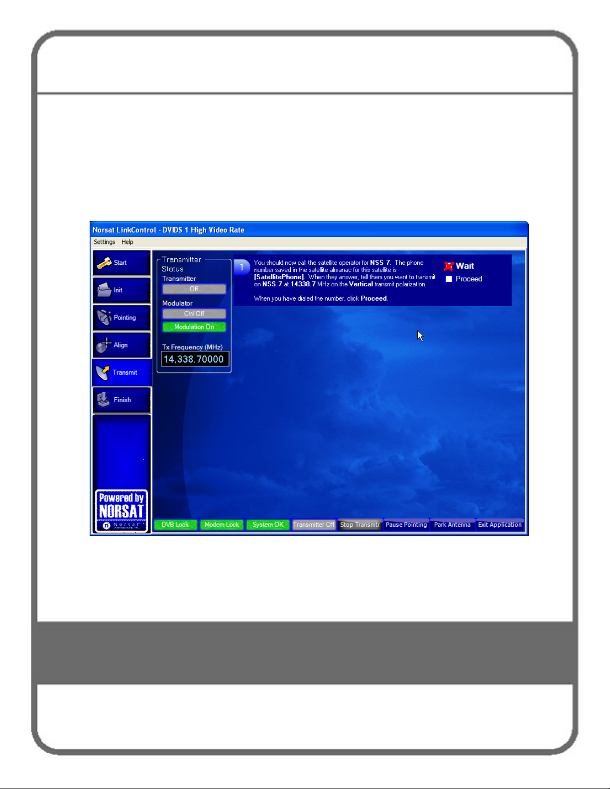
When the terminal is ready to transmit, the Transmit screen opens as shown in Figure
40. Before you can start transmitting you must call into the Satellite Operator to gain
access to the satellite. Follow the instructions of the Satellite Operator to avoid the risk
the possibility of fines.
Figure 40. Transmitting Screen
Note: If you need to stop your transmission at any time, click the Stop Transmitter
button at the bottom of the screen. If you are ready to end transmission, click
Finish button on the left side menu. The Finish Screen will open. Follow the
instructions.
Page 2
Operating the GLOBETrekker SNG
Standard™ in Auto-Acquire Mode
112
The Call
The following screen in LinkControl will tell you when to call the Satellite Operator.
Satellite Operators generally advise you to call 10 to 15 minutes before the scheduled
transmission time. These screens will help walk you through the call with the Satellite
Operator.
Hint: Have the phone number for the Satellite Operator ready in advance. When you are ready to call,
click the Proceed button as shown in Figure 41.
1 You should:
i. Have a (mobile) telephone number where the Satellite Operator can reach
you;
ii. Identify yourself and provide your location;
iii. Indicate that you have scheduled satellite time;
iv. Indicate the purpose of your transmission (example: data transfer) / video
feed;
v. Indicate that you are ready to start transmitting on satellite, transponder and
frequency slot allocation (example: NSS7, Transponder K18, Slot C).
The Satellite Operator may in turn verify some parameters and ask some
questions. You should be able to find most of these answers without having to
resort to administrator mode.
Such parameters/ questions may include:
• Are you aligned and peaked on the satellite?
• Modem settings
• Confirm Uplink frequency and polarization
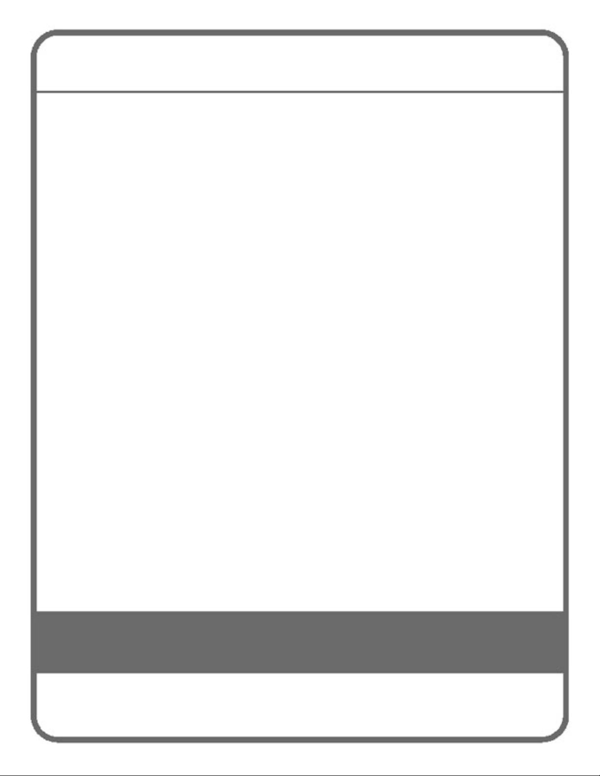
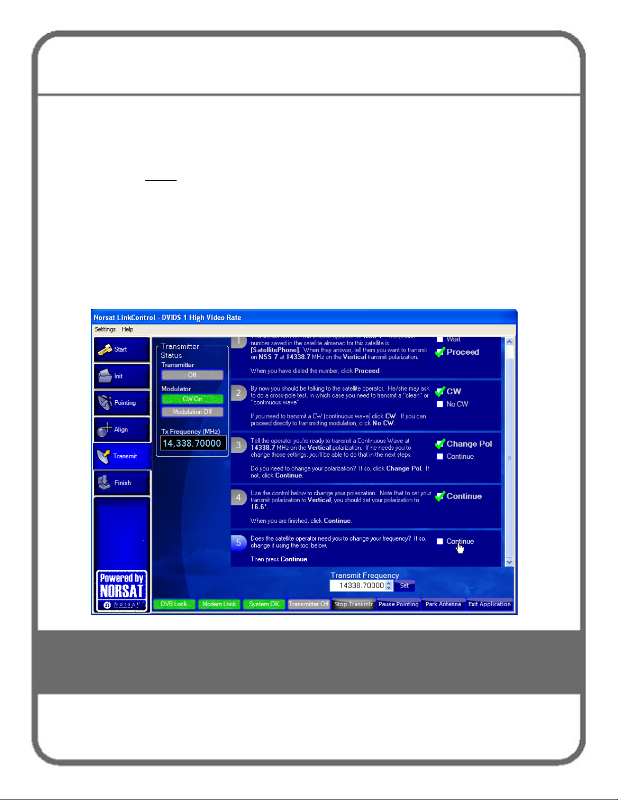
2 The Satellite Operator may then ask you to conduct a “cross-pol test”.
You may be asked for to bring up a “clean carrier” (or “unmodulated carrier” or
“continuous wave” or “CW”) at low power.
Page 3
Operating the GLOBETrekker SNG
Standard™ in Auto-Acquire Mode
113
3 Click the CW box as shown in Step 2 of Figure 32 if you are asked to complete
this step. If he doesn’t ask you to complete this step but to simply proceed
directly to transmitting mode, click the No CW box.
Note: LinkControl will then guide you through the rest of the CW transmission
process.
Figure 41. Satellite Access Procedure Screen - CW
Page 4
Operating the GLOBETrekker SNG
Standard™ in Auto-Acquire Mode
114
)
)
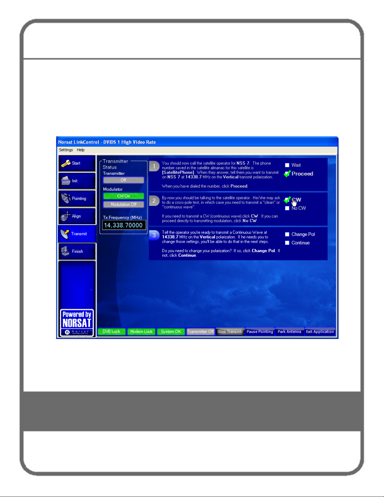
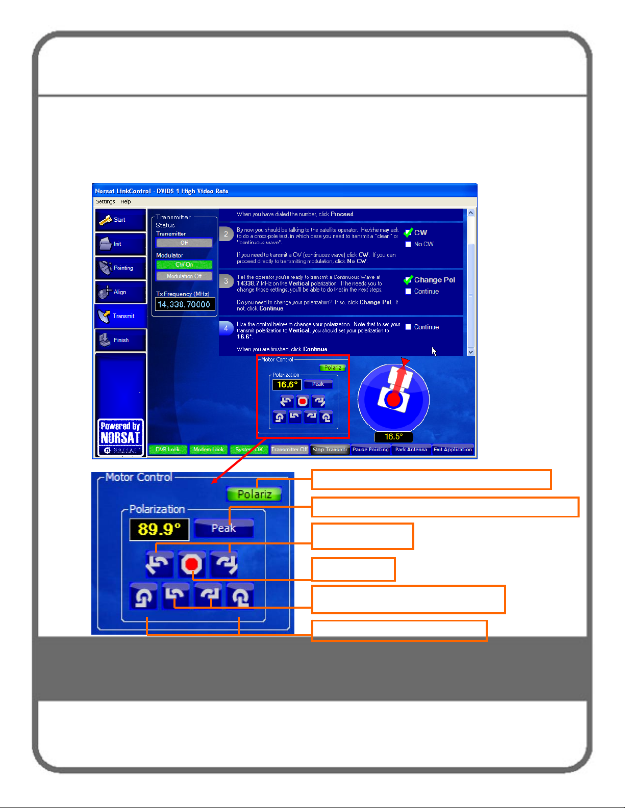
4 The Satellite Operator may then ask you to adjust your polarization. Select
the Change Pol box in Step 3. Link Control will then open the polarization
adjustment controls as shown in Figure 42. Use the Polarization control
buttons to adjust.
Figure 42. Satellite Access Procedure Screen – Change Polarization
Indicates Polarization controls (no user interaction
Placeholder button for Manual Mode; no user interaction
Nudge ± 0.2-0.3º
Stop adjusting
Continuous adjustment (medium speed)
Continuous adjustment (fast speed)
Page 5
Operating the GLOBETrekker SNG
Standard™ in Auto-Acquire Mode
115
5 When you are finished with the polarization adjustment, or are not asked to
adjust your polarization, click Continue.
Hint: If you are asked to make an adjustment to your Transmit Frequency
before
screen which allows you to change the transmit frequency (Figure 43). Once
frequency adjustment completed you can go back and make your polarization
adjustment should the Satellite Operator ask you to do so.
6 You may be asked to change your transmit frequency. LinkControl will
present you with the Transmit Frequency display which you can change
with the “up” and “down” arrows, or type a value into the field, as shown in
Figure 43. When finished adjusting the frequency, click the Continue box.
Figure 43. Satellite Access Procedures – Change Transmit Frequency
your polarization, simply click Continue which brings you to the
Page 6
Operating the GLOBETrekker SNG
Standard™ in Auto-Acquire Mode
116
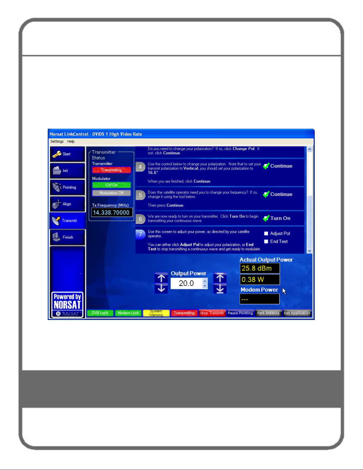
7 The transmitter is now ready to be turned on. Click the Turn On box when
you are ready as shown in Figure 44 to power up your transmitter.
8 Once you click on the Turn On button, you are transmitting and are then
presented with the next screen to adjust your output power level as shown in
Figure 44.
Figure 44. Satellite Access Procedures – Turn on Transmitter and Adjust Output Power
9 The Satellite Operator may also ask you to adjust your power level. When
directed, slowly increase power to operating level and stop. Figure 44
displays the power control adjustment control in the lower part of the screen.
Page 7
Operating the GLOBETrekker SNG
Standard™ in Auto-Acquire Mode
117
Hint: Under the guidance of the Satellite Operator, use the buttons to the left
of the Output Power display to adjust the power level in 1.0 dB steps and
use the buttons on the right of the Output Power display to adjust the power
in 0.1 dB steps. Watch the results in the Actual Power Output display area.
10 The Satellite Operator may ask you to re-adjust your polarization. If asked to
do so, click the Adjust Pol box as shown in Figure 44 (to open the
Polarization adjustment window, as shown in Figure 42); otherwise, click the
End Test box.
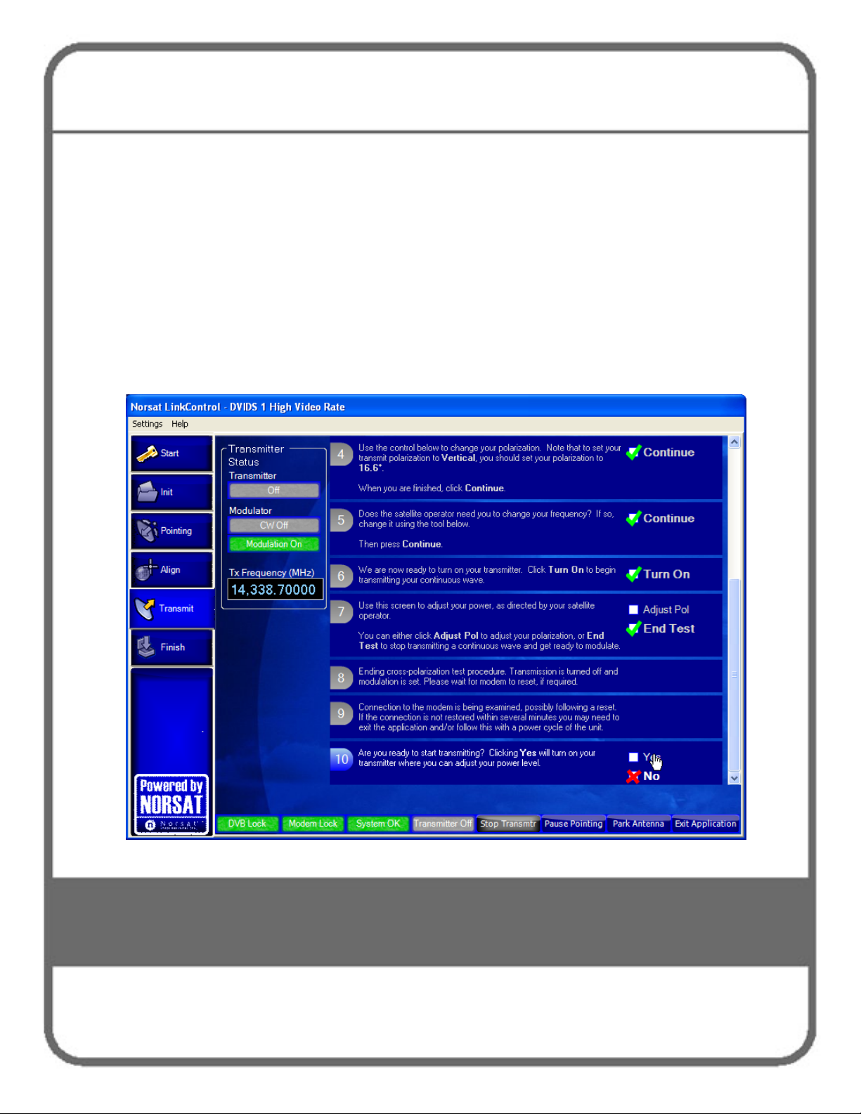
11 Once you have clicked the End Test box, see Figure 45. The system ends
the cross pol test, turns transmission off, and enables modulation.
Figure 45. Satellite Access Procedure Screen – End Test
Page 8
Operating the GLOBETrekker SNG
Standard™ in Auto-Acquire Mode
118
12 LinkControl then proceeds to Step 10 which provides the interface to turn the
transmitter on only when instructed to do so by the Satellite Operator. Wait
for further instructions from the Satellite Operator while carrier specifications
are checked (typically, by the hub operator).
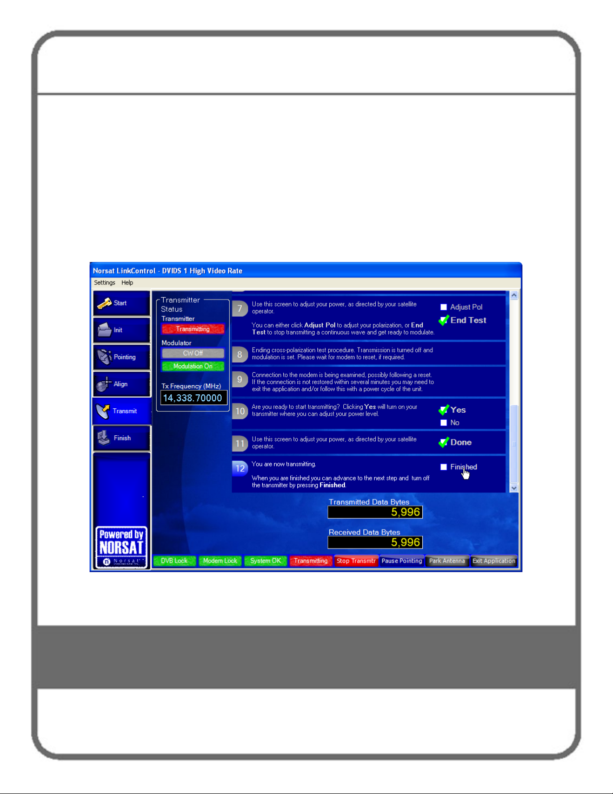
13 When directed, modulate the signal (start transmitting) by clicking the Yes
box as shown in Figure 46 Step 10. The Satellite Operator may then as you
to re-adjust your power (power adjustment will re-open – Figure 44). Wait for
further instructions from the Satellite Operator while carrier specifications are
re-checked. Follow his instructions and click Done when instructed to do so.
Figure 46. Satellite Access Procedure Screen - Transmitting
14 The Satellite Operator will verify your phone number and the end time for
your uplink. LinkControl will remind you to call the Satellite Operator again
just before the end of the uplink (the “Goodnight Call”).
Page 9
Operating the GLOBETrekker SNG
Standard™ in Auto-Acquire Mode
119
Goodnight Call
The purpose of the Goodnight Call is to inform the Satellite Operator that you have
completed your transmission and that you wish to end your transmission.
1 When you are finished transmitting, contact the Satellite Operator to confirm the
end of your transmission. Then, click the Finished box in Figure 46.
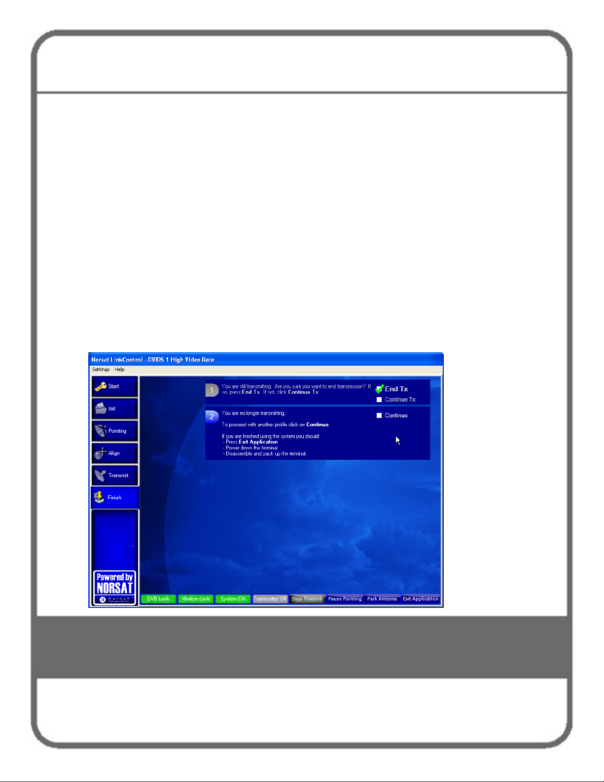
2 You will then receive an End Transmission confirmation as shown in Step 1 of
Figure 47. Click the End Tx box to turn off the transmitter. LinkControl will
confirm that you are no longer transmitting (Step 2). If you intend to stow away
the system, click the Park Antenna button to return the antenna back to its
optimal tear-down position (0º Azimuth; 0 º Polarization; 10 º Elevation). Finally,
Note: When you click the End Tx box, both lock indicators, the Transmitter Off (previously
Figure 47. Satellite Access Procedure Screen – End Transmission
click the Exit Application button to close LinkControl.
Transmitting in red) and Stop Transmtr buttons will turn grey; the Pause Pointing, Park
Antenna, and Exit Application buttons will be blue; the DVB Lock and System OK buttons
should remain green.
Page 10

120
9 Operating the
GLOBETrekker SNG
Standard™ in Manual Mode
Page 11

Operating the GLOBETrekker SNG
Standard™ in Manual Mode
121
This chapter enables a user to operate LinkControl in Manual (or Administrator) Mode to
manually align the antenna towards the desired satellite; verify and peak on the correct
satellite; and communicate with the Satellite (or Hub) Operator for transmission.
There are ten steps in the manual operation:
1. Launch LinkControl Application and Enter Administrator Mode
2. Choose a Profile
3. Identify Location
4. Verify Target Satellite
5. Check Clearance Distance
6. See the Sky View
7. Check if there is a DVB Carrier on the target Satellite
8. Point the Antenna
9. Acquire Satellite and Peak Antenna
10. Call the Satellite (or Hub) Operator to Access Satellite
Launch Link Control Application and Enter Administrator Mode
The LinkControl application will launch automatically once the GLOBETrekker SNG
Standard™ has been powered up.
Access to the LinkControl application screen will be available on the wired display
provided with the GLOBETrekker SNG Standard™ system when the system has been
powered up.
It may take several minutes for the application to appear on the screen. The application
will open with the Startup screen being displayed as in Figure 48.
Note: Click the Details button on the Startup screen to view System Status Details.
The LinkControl application performs numerous diagnostics upon start-up.
The operator should allow the LinkControl application to fully complete its
diagnostics before attempting to take control of the application. The results of the
diagnostics can be viewed by pressing the DETAILS button below the System
Status indicator.
Page 12

Operating the GLOBETrekker SNG
Standard™ in Manual Mode
122
Figure 48. LinkControl Startup Screen
Operating the GLOBETrekker SNG Standard™ in manual mode is password-protected
and is accessible only to users designated as "administrator(s)" in LinkControl.
If you are using the GLOBETrekker SNG Standard™ for the first time, the system will
come with an Administrator password. This can be changed at a later date.
To enter Administrator mode:
1 On the Menu bar press Settings -> Enter Admin Mode
2 Enter the Administrator password. By default the password is “Administrator”.
Note: Passwords are case sensitive
To exit Administrator mode and enter Operator mode:
1 On the Menu bar press Settings
2 Select Exit Admin Mode
Page 13

Operating the GLOBETrekker SNG
Standard™ in Manual Mode
123
Choose a Profile
Choose an Existing Profile:
a Click on the Profiles tab on the left side of the screen; refer to Figure 49.
b Click on a profile in the list of profiles under Choose a profile.
Note: To create or edit a profile, refer to the instructions in Chapter 7:
Commissioning the GLOBETrekker SNG Standard™.
c A summary of the selected profile is displayed on the right side of the screen.
Figure 49. Choose a Profile
Page 14

Operating the GLOBETrekker SNG
Standard™ in Manual Mode
124
Identify Location
To correctly point the antenna to a desired satellite:
Click Antenna Pointing on the Toolbar. The Antenna Pointing Screen opens as
shown in Figure 50. The Antenna Orientation fields display the antenna pointing
values.
Figure 50. Antenna Pointing Screen
The world map in Figure 50 shows the GLOBETrekker SNG Standard™ position and
the position of the selected satellite.
Page 15

Operating the GLOBETrekker SNG
Standard™ in Manual Mode
125
Ground Location
The LinkControl application must know your current ground location in order to calculate
the look angles required to point the antenna at the satellite.
The location of the terminal can be determined in three different ways:
i) selecting your location from the City list;
ii) by using the supplied GPS receiver;
iii) by manually entering the latitude and longitude.
If the selected profile does not already have the GLOBETrekker SNG Standard™’s
current location, use the following steps:
To select location from the city list:
1 Click on Select City
2 Expand the continent and country trees by clicking on the + sign.
3 Click on the nearest city.
4 Click OK.
To determine location using the GPS:
1 Ensure the GPS is connected. If this was not done during the set up, the GPS
will not be initialized.
To initialized the GPS:
a Click on View GPS Data
b Click on Initialize
c Click on Close
2 If the Use GPS Data button is green, it has acquired a location. Press the button
to use the GPS information as its position.
Note: The GPS unit requires a clear and unobstructed view of the sky to operate
properly. If portions of the sky are blocked, it may impact acquisition time.
Page 16

Operating the GLOBETrekker SNG
Standard™ in Manual Mode
126
To manually enter latitude and longitude:
1 Enter the Latitude in the box or select the value using the scroll arrows.
2 Select the North or South radio button.
3 Enter the Longitude in the box or select the value using the scroll arrows.
4 Select the East or West radio button.
Note: The format for latitude and longitude is <Degrees.Decimal Degrees>
Verify Target Satellite
Confirm the satellite name that appears in the white Target Satellite box on the Select
Satellite drop down screen (Figure 50).
Check Clearance Distance
1 Click on the Alignment tab.
2 On the Alignment screen, click the Clearance Distance tab (Figure 51).
3 Ensure that there are no obstructions within the clearance range listed.
For more information on clearance distances refer to Chapter 1 – Safety Basics.
Page 17

Operating the GLOBETrekker SNG
Standard™ in Manual Mode
127
Figure 51. Clearance Distance
See the Sky View
The Sky View screen, as shown in Figure 52, gives the operator a view of the satellites
adjacent to the desired satellite. This tool is a visual aid to help the operator if they
suspect that they are pointed ona satellite, but not necessarily the correct satellite.
The arc described by the adjacent satellites is drawn from the operator’s point of view.
The desired satellite is highlighted in orange.
Page 18

Operating the GLOBETrekker SNG
Standard™ in Manual Mode
128
Figure 52. Sky View Screen
Check if there is a DVB Receiver on the Target Satellite
1 Click the DVB Receiver Lock tab on the right side menu.
2 Check to see if a DVB carrier appears in the box in the upper right corner as
shown in Figure 53.
3 Select a DVB carrier if one is present (DVB listed to the right of the Current Rx
Polarization: section as shown in Figure 53).
Page 19

Operating the GLOBETrekker SNG
Standard™ in Manual Mode
129
Figure 53. DVB Receiver Lock
If no DVB carriers appear in the box, you will need to rely on the presence of either a
beacon or alignment carrier when acquiring the satellite signal. That is, the No DVB
Lock button (bottom-left screen) will remain grey throughout the entire satellite
acquisition process.
Page 20

Operating the GLOBETrekker SNG
Standard™ in Manual Mode
130
Point the Antenna
Once the Norsat LinkControl application has its location and desired satellite, it will
automatically calculate the look angles required to point the antenna at the satellite.
The application calculates four values:
• Compass Azimuth – magnetic compass bearing to which the antenna should be set
• Elevation – angle to which the inclinometer should be set
• Polarization – angle to which the feed should be rotated
• True Azimuth – bearing relative to Geographic North rather than Magnetic North
Aligning the Antenna
To align the antenna, click Alignment on the GLOBETrekker SNG Standard™
Functions Toolbar on the left side menu. The Alignment screen opens (Figure 54).
Figure 54. Antenna Alignment
Page 21

Operating the GLOBETrekker SNG
Standard™ in Manual Mode
131
Adjusting Antenna Elevation
To adjust the antenna elevation, adjust the elevation of the antenna to match the
degrees as shown in the Elevation field (as shown in Figure 54) using the arrows inside
the Elevation positioning box. The arrow of the elevation adjustment diagram will change
color from red to green when you have reached the calculated elevation value.
Peak Elevation
Nudge ± 0.1º
Stop adjustment
Continuous adjustment (fast speed)
Continuous adjustment (medium speed)
Page 22

Operating the GLOBETrekker SNG
Standard™ in Manual Mode
132
Setting Antenna Polarization
Set the Tx polarization to match the value set in the Transmit Polarization field (as
shown in Figure 54) using the arrows inside the Polarization positioning box. The arrow
of the polarization adjustment diagram will change color from red to green when you
have reached the calculated polarization value.
Peak Polarization
Nudge ± 0.1º
Stop adjustment
Continuous adjustment (medium speed)
Adjusting the Azimuth
Do not attempt to adjust the Antenna Azimuth to match the Compass Azimuth reading.
Instead, using the Azimuth controls, adjust the azimuth until the diagram arrow
turns green.
Then, proceed to the next section on Acquire Satellite and Peak Antenna by
clicking the Receiver Spectrum Analyzer tab (Figure 55).
Continuous adjustment (fast speed)
Acquire Satellite and Peak Antenna
Acquiring the satellite and peaking the antenna involves the use of the built-in spectrum
analyzer and a DVB lock indicator (in the case of a DVB carrier).
Page 23

Operating the GLOBETrekker SNG
Standard™ in Manual Mode
133
The process of acquiring a satellite and peaking the antenna is easiest when a satellite
has a DVB carrier and a beacon. Where a DVB carrier does not exist a beacon can still
be used.
Note: When neither a DVB carrier nor a beacon exists, other types of carriers, if present,
and/or reference satellites can still be used to acquire a particular satellite. This chapter does
not address such occurrence. To learn more about how to handle such situations, attend a
Norsat training session.
The reference level (dBm) and the dB per division functions will be set to auto mode
(these are pre-selected and set from the factory).
Note: Advanced users can deselect either or both the reference level and the dB per division
in order to configure the spectrum analyzer to settings of their choice. Additionally, the Center
Frequency and Frequency Span are also adjustable using scroll arrows.
The process of acquiring a satellite and peaking the antenna requires the use of the
Spectrum Analyzer Screen.
Viewing the Receive (Rx) Spectrum Analyzer Screen
To open the Receiver Spectrum Analyzer Screen, click the down arrow beside the
Spectrum Analyzer. The Receive Spectrum Analyzer Screen opens as shown in
Figure 55.
Page 24

Operating the GLOBETrekker SNG
Standard™ in Manual Mode
134
The Receive Spectrum Analyzer screen, shown in Figure 55 displays physical
parameters along the X axis and the Y axis as follows:
frequency along the X axis
signal amplitude along the Y axis
Figure 55. Alignment Screen with Rx Spectrum Analyzer
Table 5 lists the various controls and functions for the Receive Spectrum Analyzer.
Refer to Figure 55 for the locations and descriptions of the control buttons.
Page 25

Operating the GLOBETrekker SNG
Standard™ in Manual Mode
135
Table 5. Controls on the Rx Spectrum Analyzer
Controls Functions
Rx Spectrum Analyzer
1. Center frequency (MHz) To change the Center frequency, complete the following steps:
1 Click the up/down arrows to increase or decrease the
frequency OR
2 Type in the desired frequency OR
3 Use the horizontal arrows to adjust the frequency.
4 Set a marker to the desired frequency.
5 Click on either Marker 1 or Marker 2 depending on the pre-
selected frequency setting.
Note: see number 5 in table for more detail.
2. Reference level (dBm) To adjust the Reference level field, complete the following steps:
1 Click the up arrow to increase the reference level by 5dB. This
moves the trace down the screen.
2 Click the down arrow to decrease the reference level by 5dB.
This moves the trace up the screen.
Hint: the check box to the right of the Reference Level settings
should be unchecked (deselected) to make manual changes to the
reference level settings and checked (selected) when the system is
operating.
Note: see number 5 in table for more detail.
3. Frequency Span (MHz) To adjust the Span frequency, use the + / - buttons and complete the
following steps:
1 Click the right +button to decrease Span frequency.
2 Click the left - button to increase the Span frequency.
Note: see number 6 in table for more detail.
Page 26

Operating the GLOBETrekker SNG
Standard™ in Manual Mode
136
Table 5. Controls on the Rx Spectrum Analyzer - continued
Controls Functions
Rx Spectrum Analyzer
4. dB per division To adjust the dB per div, use the + / - buttons and complete the
following steps.
1 Click the upper + button to decrease the dB per div by 1dB.
2 Click the lower - button to increase the dB per div by 1dB.
3 Range is 3 to 10dB per division in steps of 1 dB.
Hint: the check box to the right of the Reference Level settings should
be unchecked (deselected) to make manual changes to the reference
level settings and checked (selected) when the system is operating.
Note: see number 6 in table for more detail.
5. Frequency Adjust and
Reference Adjust
6. Frequency Span and
Strength Span Adjust
Frequency adjustment controls (center frequency):
Are the Left and Right arrow buttons.
Left arrow for DOWN frequency adjust and Right arrow for UP
frequency adjust.
Reference adjustment controls (reference level):
Up and Down arrow buttons.
Up arrow for UP reference adjust and Down arrow for DOWN
reference adjust.
Frequency Span adjustment controls (frequency span):
Are the Left and Right Minus/Plus signs.
Left side Minus Increases frequency span and Right side Plus
sign Decreases frequency span.
Strength Span adjustment controls (dB per division):
Are the Top and Bottom Plus/Minus signs.
Top Plus sign Decreases strength span and Bottom Minus sign
Increases strength span.
Page 27

Operating the GLOBETrekker SNG
Standard™ in Manual Mode
137
Table 5. Controls on the Rx Spectrum Analyzer - continued
Controls Functions
Rx Spectrum Analyzer
7. Detail Detail controls the number of sweep samples used in drawing the
signal trace in the Spectrum Analyzer.
Increasing the sweep detail increases the amount of time required to
draw the trace on the spectrum analyzer. It is normal to leave this set
to high detail as it may be difficult to distinguish signals when the detail
is set too low.
Detail changes the resolution bandwidth of the Spectrum Analyzer. The
following resolution bandwidths are available:
600Hz, 1.2KHz, 2.4KHz, 4.9KHz, 9.8KHz, 19.5KHz and
39.1KHz
8. Signal Averaging Controls the number of sweep samples averaged and displayed as one
trace; Averaging ranges from 1 (no averaging) to 16.
9. Rx and Tx polarization Rx polarization radio buttons control the types of carriers which appear
in the carrier selection list.
This enables a user to check for a known signal on the opposite
polarization to help verify the correct satellite.
To view alternate polarization signals, complete the following steps:
1 Click the radio button to select the type of polarization.
2 Adjust the polarization settings on the feed assembly.
3 Return to the desired polarization type before Tx.
10. Carrier selection list The carrier selection list enables a user to set the spectrum analyzer to
view a particular signal.
Clicking on a carrier in the list automatically sets the Center frequency
and Span to match the selected carrier.
Page 28

Operating the GLOBETrekker SNG
Standard™ in Manual Mode
138
Table 5. Controls on the Rx Spectrum Analyzer - continued
Controls Functions
Rx Spectrum Analyzer
11. Marker Functions (MHz) Measures the amplitude difference (marker delta); the bandwidth of
signals and changes the Center frequency
To set a marker, complete the following steps:
1 On the Spectrum Analyzer, move the pointer to the spot you
wish to mark.
2 To set Marker 1, left click with mouse, Marker1 is displayed as
a blue arrow.
3 To set Marker 2, right click with mouse, Marker 2 is displayed
as an orange arrow.
The acquisition process involves:
1 Choosing a DVB-S carrier or Beacon carrier from the list as shown in Figure 55.
2 Sweeping for a Signal.
a Click on the Azimuth button in the Motor Control box, as shown in Figure 55.
b Within the Motor Control box of the screen, click Azimuth and, using the
controls, nudge the Azimuth the Signal Level reading is maximized.
Graphically, you should observe the greatest peak on the Spectrum Analyzer.
(If no signal appears or is visible, use different carrier or change Span).
Page 29

Operating the GLOBETrekker SNG
Standard™ in Manual Mode
139
Peak Azimuth
Nudge ± 0.1º
Stop adjustment
Continuous adjustment
3 Verifying the satellite. Perform the following for each of the carriers that appear in
Figure 55.
a Select the carrier, either DVB carrier or Beacon carrier.
b Look at the Receive Spectrum Analyzer screen and if the beacon carrier is
chosen, ensure that spike appears in middle of the screen. If DVB carrier is
chosen, ensure that signal is in the center of the screen and that list
bandwidth is close in width to the horizontal line (indicator) displayed on the
screen.
You are now pointing at the satellite and need to peak the antenna to maximize your
signal strength.
Continuous adjustment
 Loading...