

Page 1
This manual contains safety information that if ignored can
endanger life or result in serious injury. They are indicated
by this icon.
Keep the instrument protected from sun and water.
Avoid water splashes.
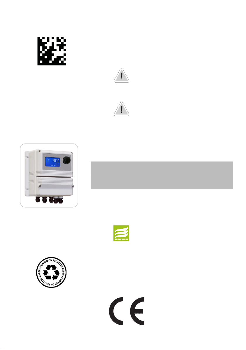
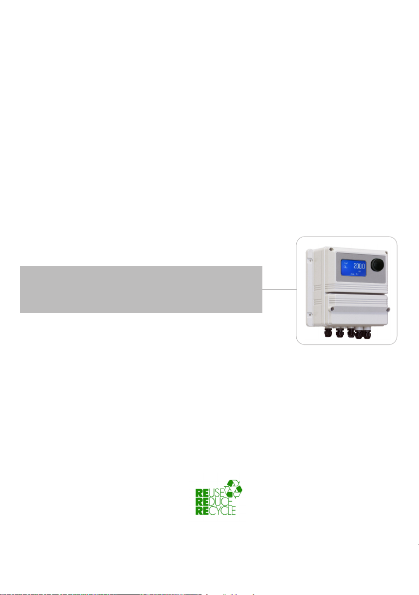
OPERATING INSTRUCTIONS FOR
“LDSCD PLUS” / “LDSCDIND PLUS” / “LDSCDIND PLUS D”
INSTRUMENT SERIES
DOWNLOAD ERMES COMMUNICATION SOFTWARE
www.ermes-server.com
Read Carefully !
1
ENGLISH Version
R14-12-18
Page 2
NORME CE
EC RULES(STANDARD EC)
NORMAS DE LA CE
Direttiva Bassa Tensione
Low Voltage Directive
Directiva de baja tensión
Direttiva EMC Compatibilità Elettromagnetica
EMC electromagnetic compatibility directive
EMC directiva de compatibilidad electromagnética
2014/35/UE
⎬
GENERAL SAFETY GUIDELINES
2014/30/UE
⎬
Danger!
Caution!
In emergencies the instrument should be switched off immediately! Disconnect the power cable
from the power supply!
When installing always observe local regulations!
Manufacturer is not liable for any unauthorized use or misuse of this product that may cause injury,
damage to persons and / or materials.
Instrument must be accessible at all times for both operating and servicing. Access must not be
obstructed in any way!
Feeder should be interlocked with a no-flow protection device to automatically shut-off the pumps
when there is no flow!
Pumps and accessories must be serviced and repaired by qualified and authorized personnel only!
Always discharge the liquid end before servicing the instrument!
Empty and rinse the liquid end before work on a pump which has been used with hazardous or
unknown chemicals!
Always read chemical safety datasheet!
Always wear protective clothing when handling hazardous or unknown chemicals!
Instrument must be operated / serviced by trained technicians only!
All connection operations must be performed while the instrument is not connected to main
supply!
Missed activation for Min/Max alarm and Maximum Dosing Alarm may cause hazardous overdosing!
2
Page 3
1. Introduction
LDSCD is a microprocessor based digital regulator for conductivity with temperature reading and mA module (feed
forward). On/Off, impulsive proportional, proportional PWM or fixed PWM, Water Meter and PID are main working
modes. Also available FEED FORWARD setting for mA module. Pulses per minute can be set for outputs. Working ranges
are: Conductivity: from 0 to 10 mg/l. All information are provided through a large LCD display. Using a revolutionary
wheel control the instrument can be easily programmed. LDSCD is housed in a IP65 plastic box.
For LDSCD PLUS D version refers to page 31.
OUTPUTS:
INPUTS:
- Stand-by
- Flow
- Conductivity level
- Conductivity probe
- Temperature probe
- Water Meter
- 2 relay outputs (CD and alarm)
- 2 opto coupled pulses outputs (CD and temperature)
- 2 current outputs (CD and Temperature)
- Main alarm
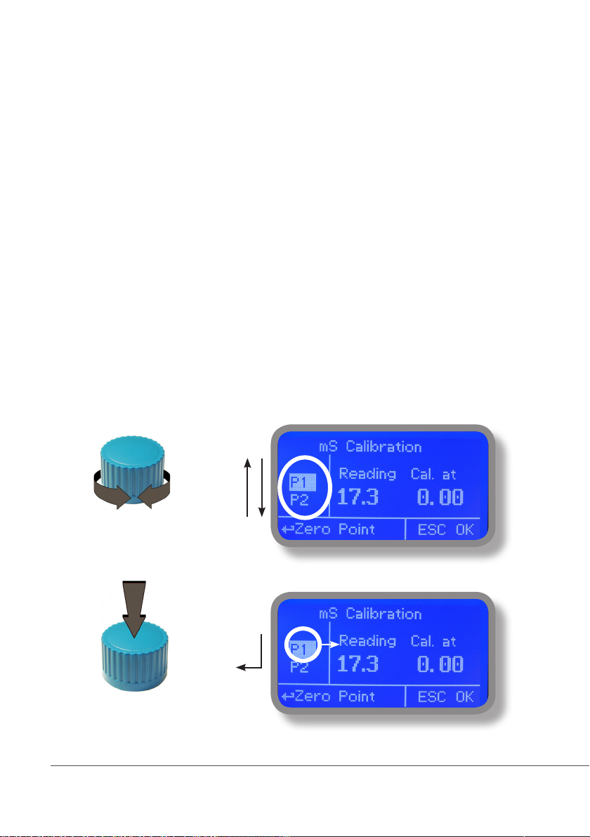
2. The wheel
Located in the upper right side of LDSCD there is a wheel that must be used to control the instrument. Wheel can
be rotated in both directions to scroll over the menus and / or pressed to confirm highlighted selection / value.
NOTE: Once changes are made press “OK” to save and exit from submenu. Press “ESC” to exit without saving.
Rotate wheel to scroll through menus or options
Press wheel to select highlighted option
3
SCROLL
Page 4
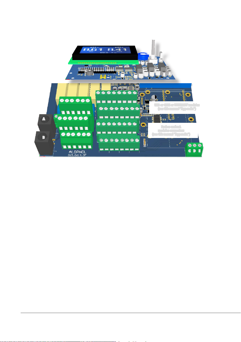
3. Mainboard Connections
Unplug instrument from main power supply then perform connections by following the above picture.
DISPLATY BOARD
MAIN
BOARD
L 1 2 3 4 5
A
E E E E E E
B
A: Main Fuse (6A T)
B: Instrument Fuse (3.15A T)
C - D - E : Factory reserved +5V
L(Live) - E(Earth) - N(Neutral): 85÷264VAC* or 18÷36VAC* 50/60 Hz *see instrument’s label
1(Live) - E(Earth) - N(Neutral): 85÷264VAC - 5A 50/60 Hz Relay Output “CD Relay 2”. To use with ON/OFF or PWM device
2(Live) - E(Earth) - N(Neutral): 85÷264VAC - 5A 50/60 Hz Relay Output “CD Relay”. To use with ON/OFF or PWM device
3(Live) - E(Earth) - N(Neutral): 85÷264VAC alarm output (MAX 5A)
4(Live) - E(Earth) - N(Neutral): 85÷264VAC “SELF CLEAN” output (MAX 5A)
5(Live) - E(Earth) - N(Neutral): 85÷264VAC “CIRCULATOR PUMP” output (MAX 5A)
6(Green) - 7(Brown) - 8(White) - 9(Yellow): PT100 temperature probe (remove jumper / resistor prior to install probe)
11(-) - 10(+): Standby contact* *for LDSCIND-C version contact is “N.C.” Normally Closed
11(-) - 12(+): CD Level 1 contact
19(-) - 18(+): CD Level 2 contact
14(+ Brown) - 15(Black) - 16(- Blue) - 17(GND): Proximity sensor mod. “SEPR” (dont’ remove jumper between blocks 16 and 17)
21(GND) - 28(+RS485) - 29(-RS485): RS485
24(-) - 25(+): Opto coupled output “CD PULSE”. To use with “IS” , “MF” , “PLUS” series dosing pumps
26(-) - 27(+): Opto coupled output “CD PULSE 2”. To use with “IS” , “MF” , “PLUS” series dosing pumps
31(-) - 32(+): mA Current Output CD
34(-) - 35(+): mA Current Output Temperature
31(-) - 30(+): mA Current Output PID
36(+) ; 37(-): WM Input (max input frequency 500Hz)
N N N N N N
30 31 32 33 34 35 36 37
22 23 24 25 26 27 28 29
14 15 16 17 18 19 20 21
6 7 8 9 10 11 12 13
(no MODBUS)
Max resistive load: 500 Ohm
⎬
USB or GSM or ETHERNET modules
(see this manual “Appendix”)
Probes and mA
modules connectors
(see this manual “Appendix”)
C D E
Warning: Connections must be perfomed by qualified and trained personnel only.
4
Page 5

4. Main Screen
When into normal operating mode, LDSCD shows the following main screen:
GSM Signal*
UNIT (1)
LAN CONNECTION OK - ERMES CONNECTION OK
VALUES (2)
OUTPUTS STATUS (3)
WARNING MESSAGES
NOTIFICATION AREA
LAN CABLE DISCONNECTED
LAN CABLE CONNECTED - ERMES NOT AVAILABLE
CONNECTED TO USB PEN-DRIVE
ERMES OK
Main screen zones:
(1) UNIT Values read by the probe. “mS” - “uS” - “PPM/TDS”* are the measuring unit
for Conductivity probe. To change unit refer to “International” menu.
(2) VALUES These numbers are values read by the probes.
According to selected probe, this field may appear different.
Connection Status
(3) OUTPUTS STATUS These fields are related to current outputs status and instrument activity.
For more information rotate the wheel when into main screen. (see next page)
During critical situations a warning / alarm message may appear. To
WARNING MESSAGE
NOTIFICATION AREA
in-depth explanation completely rotate clockwise the wheel to review main
instrument parameters and current outputs status.
*sold as option
*PPM / TDS unit is based on 1mS = 640 PPM of TDS (total dissolved solids)
Note: the word “PUMP” as shown into this manual refers to a “dosing device” connected to the instrument!
5
Page 6
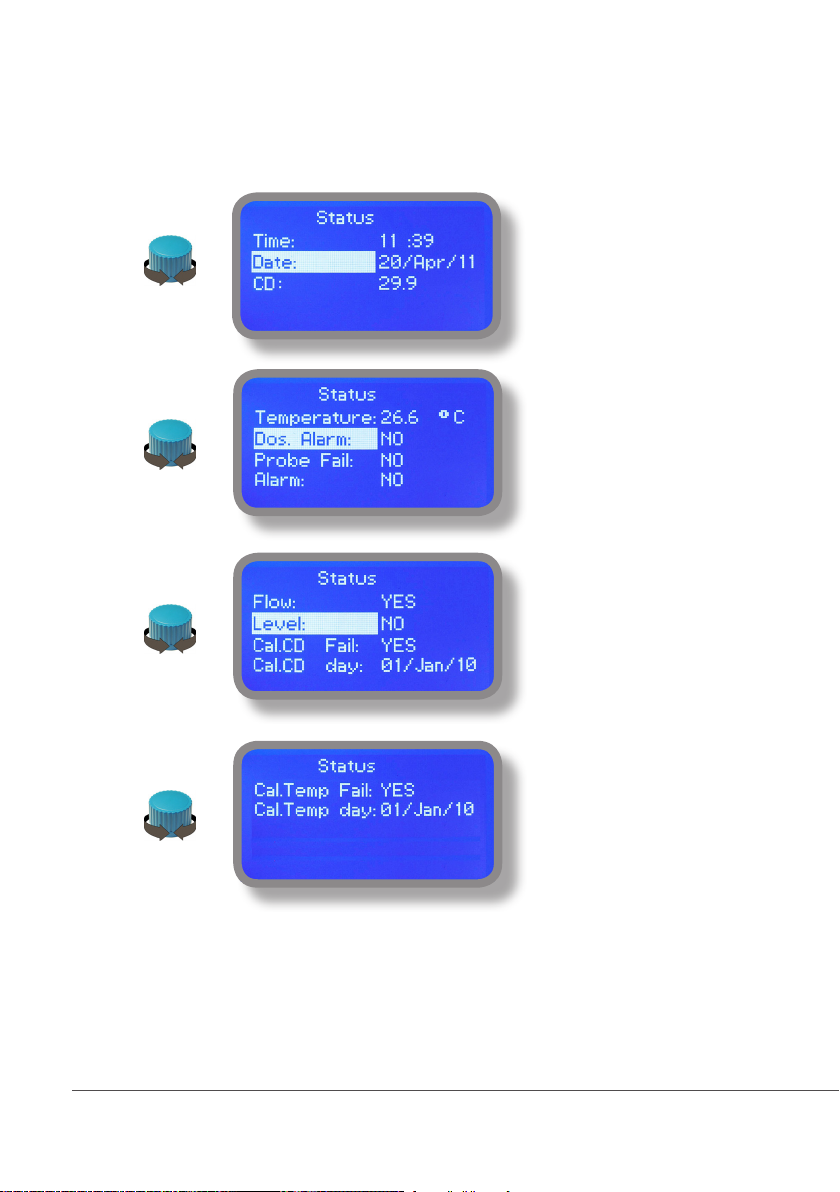
5. Quick status check
From main screen completely rotate clockwise the wheel to review main instrument parameters and current outputs
status.
Local Time
Local Date
Conductivity probe reading
Temperature probe reading
Dosing alarm condition
Probe failure status
Alarm contact status
Flow contact status
Tank Level status
Last Conductivity calibration
result
Last Conductivity calibration date
Last Temp. calibration result
Last Temp. calibration date
Outputs Status
:::
6
See mainboard (page 4) for related
connetions.
Page 7
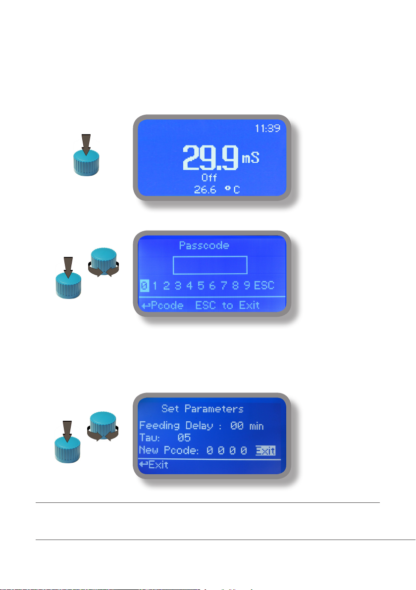
6. Password
To grant access into “Main Menu” press the wheel from main screen and enter the passcode.
If this is the first time here then the passcode is 0000 (factory preset). Press wheel 5 times to enter into “Main
Menu”. Otherwise press the wheel 1 time and enter the passcode. Numbers can be selected rotating the wheel.
X5
To set a new passcode choose “PARAMETERS” from “Main Menu” , move on “New Pcode”, click on wheel and
enter a four numbers code. Click on “EXIT” and choose “YES” to save request. The new passcode is now ready.
Lost passcode ?
Please dont’ forget the passcode (if changed). In the unfortunate event, please call your local distributor for unlocking procedure. There is no way for you
to recover lost passcode.
7
Page 8
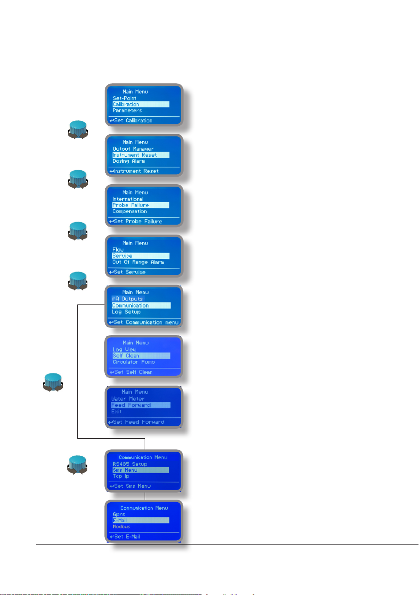
7. “Main Menu” list
To grant access into “Main Menu” enter the passcode (as described in previous chapter). Once into “Main Menu”
rotate the wheel to scroll through all the options available.
“Setpoint” (see page 9)
“Calibration” (see page 14)
“Parameters” (see page 16)
“Output manager” (see page 17)
“Instrument reset” (see page 18)
“Dosing alarm” (see page 19)
“International” (see page 20)
“Probe Failure” (see page 21)
“Compensation” (see page 42)
“Flow” (see page 22)
“Service” (see page 22)
“Out of Range Alarm” (see page 24)
“mA Outputs” (see page 23)
Communication (see below)
“Log Setup” (see page 38)
“Log View” (see page 38)
“Self Clean” (see page 25)
“Circulator Pump” (see page 26)
“Water Meter” (see page 29)
“Feed Forward ” (see page 30)
“RS485 Setup” (see page 35)
“SMS menu” (see page 35)
“TCP IP” (see page 36)
“GPRS” (see page 37)
“Email” (see page 37)
“Modbus” - (see page 39)
8
Page 9
8.1 “Set-Point”
“CD PULSE 1 ” and “CD PULSE 2” outputs can be set to operate within:
On/Off, Proportional (%) or disabled (OFF) modes.
“CD RELAY 1” and “CD RELAY 2” outputs can be set to operate within:
On/Off, Proportional PWM, Fixed PWM or disabled (OFF) modes.
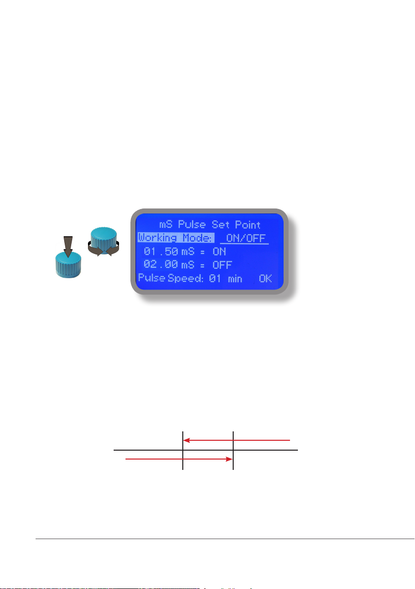
8.2 “Set-Point”, Conductivity (on/off)
All Conductivity outputs can be set to operate into this mode.
This mode enables Conductivity pump to operate between two On/Off values. Move wheel over “Working
Mode” to select it.
ON/OFF mode
Set Conductivity value at 1,50mS ON and 2,00mS OFF. The difference between the two Conductivity values is called
HYSTERESIS.
Instrument will enable the Conductivity pump when reading value will decrease at 1,50mS
At 1,50mS the Conductivity pump will be enabled until reading value will increase at 2,00mS.
Pulse Speed: pulses per minute setting.
ON
OFF
1,50 2,00
9
Page 10
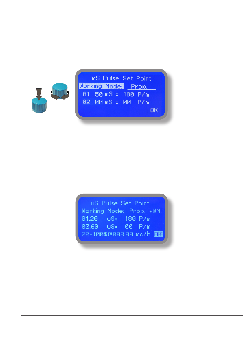
8.2 “Set-Point”, CD proportional & proportional water meter (pulse)
This mode is valid for “CD pulse” and “CD pulse 2” outputs only.
Proportional mode set the instrument to operate using a calculated percentage between two set values that
enable or disable the Conductivity pump. To use this mode move cursor on “Working Mode”. Press the wheel
and select it.
PROPORTIONAL MODE between 2,00(0 P/m) and 1,50(180 P/m). [P/m: pulses per minute]
This mode operates Conductivity pump for a value lower that 1,50mS with maximum dosing capacity (180strokes) and
it will stop Conductivity pump for a reading value higher than 2,00mS.
Proportional Water Meter
Proportional mode can also be set into PROP+WM mode. This option allows to regulate proportional input based on
flow detected by water meter at set percentual values.
e.g.: reading at 0.90 will have an output of 90 P/m (50%). Adding the proportional flow from the water meter with
parameters set between 20 % (at 0mc/h) and 100% (at 8mc/h) results will be that (as example):
At 4 mc/h will have a working period of 54 P/m (60% of 90P/m)
60% is the middle value between 20% and 100% for reading of 4mc/h
10
Page 11
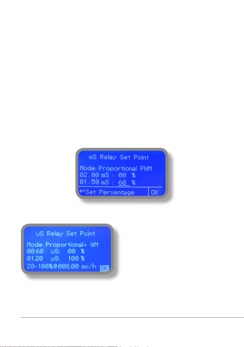
8.3 “PWM” proportional CD & proportional water meter (relay)
“CD RELAY 1” and “CD RELAY 2” outputs can be set into this mode.
Pulse-width modulation (PWM) of a signal or power source involves the modulation of its duty cycle, to either convey
information over a communications channel or control the amount of power sent to a load.
This mode works over a settable (0 to 100 seconds) time to switch on or off selected output.
Time resolution is 5 seconds, 5 steps. During this time if reading value will move towards a set value (on or off) the PWM
will operate the output on timered basis. Reaching the set value the PWM will permanently leave on or off the output.
Parameters to set are:
Unit Value + %: (time activity towards set value. 0% means 0 seconds. 100% means 100 seconds.)
mS range: two pH value between PWM operates.
E.g: set rst value at 2,00 = 00% and second value at 1,50=60%.
For reading values ≥ 2,00 output will always be OFF.
For reading values ≤ 1,50 output will be ON for 60 seconds and OFF for 40 seconds.
If reading value is 1,75 mS the ouput will be ON with a 30% of total set time. (ON for 30 seconds, OFF for 70 seconds).
Proportional Water Meter
11
Proportional mode can also be set into PROP+WM mode.
This option allows to regulate proportional input based on
flow detected by water meter at set percentual values.
e.g.: reading at 0.09 will have an output of 50 seconds
on and 50 seconds Off (50% on 100 seconds base).
Adding the proportional flow from the water meter with
parameters set between 20 % (at 0mc/h) and 100% (at
8mc/h) results will be that (as example):
At 4 mc/h will have a working period of 30 seconds ON
and 70 seconds OFF (60% of 90P/m)
60% is the middle value between 20% and 100% for
reading of 4mc/h
Page 12
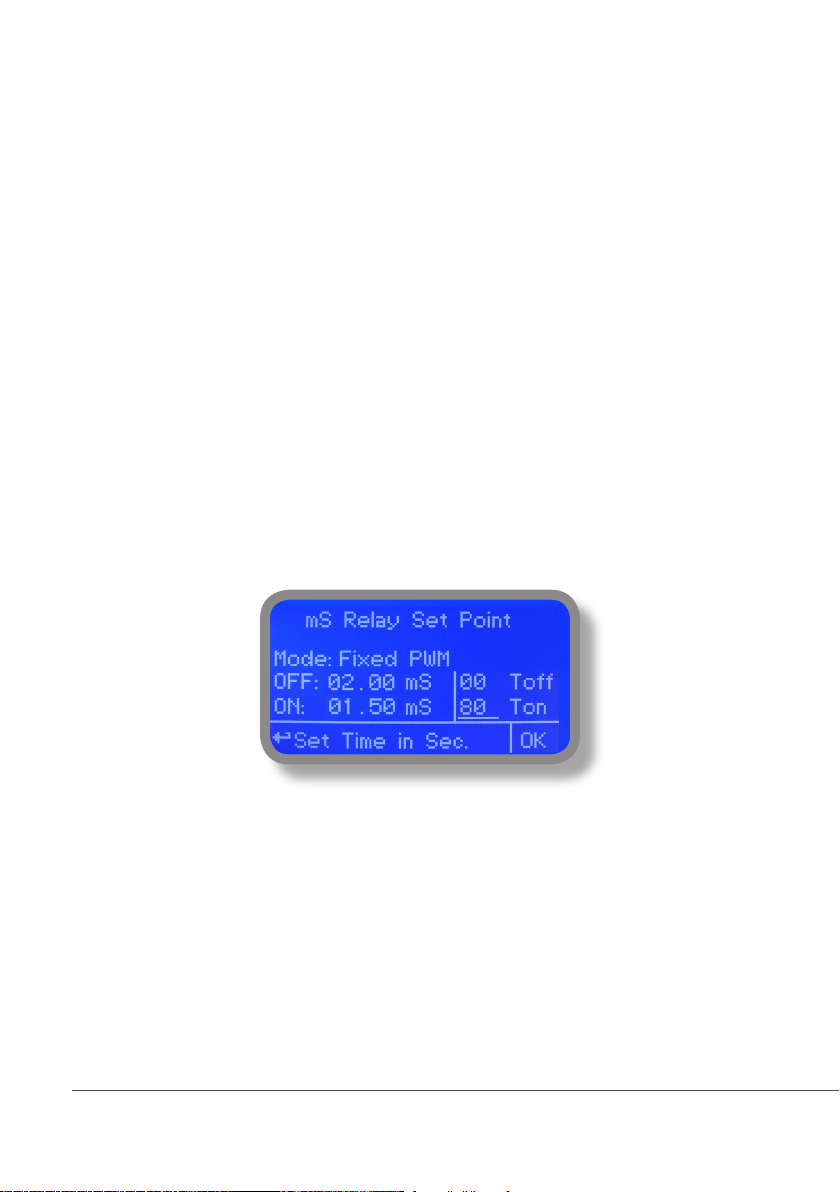
8.5 “PWM” (fixed), Conductivity
“CD RELAY 1” and “CD RELAY 2” outputs can be set into this mode.
Pulse-width modulation (PWM) of a signal or power source involves the modulation of its duty cycle, to either convey
information over a communications channel or control the amount of power sent to a load.
This mode works over a settable (0 to 100 seconds) time to switch on or off selected output.
Time resolution is 5 seconds, 5 steps. During this time if reading value will move towards a set value (on or off) the PWM
will operate the output on timered basis. Reaching the set value the PWM will permanently leave on or off the output.
Parameters to set are:
mS range: two mS value between PWM operates.
Ton: “ON” time if output is active.
Toff: “OFF” time if output is active.
E.g.: set rst mS value: (OFF) at 2,00 and second mS value: (ON) at 1,50.
Set “WORK-PAUSE” activity with Toff 0 seconds and Ton 80 seconds.
For reading values ≥ 2,00 output will always be OFF.
For reading values ≤ 1,50 output will be ON within “WORK-PAUSE” mode based on Ton and Toff settings.
Within 2,00mS and 1,50mS values output activity will operate on HYSTERESIS basis. Once 2,00mS reading value will be
reached the output will always be OFF up to 1,50mS reading value.
12
Page 13
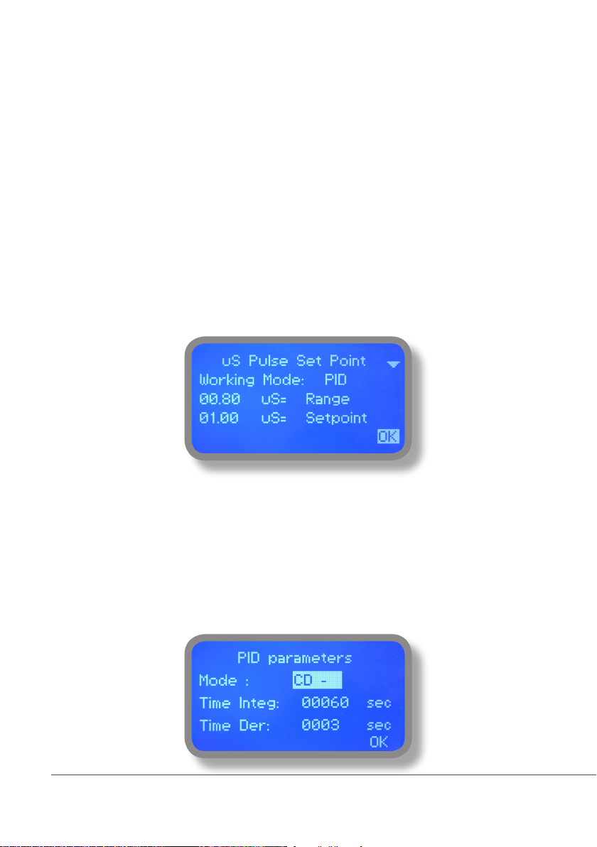
8.5 “PID”, CD
A proportional-integral-derivative controller (PID controller) is a control loop feedback mechanism (controller) widely
used in industrial control systems. A PID controller calculates an error value as the difference between a measured
process variable and a desired setpoint. The controller attempts to minimize the error by adjusting the process
through use of a manipulated variable. The PID controller algorithm involves three separate constant parameters,
and is accordingly sometimes called three-term control: the proportional, the integral and derivative values, denoted
P, I, and D. Simply put, these values can be interpreted in terms of time: P depends on the present error, I on the
accumulation of past errors, and D is a prediction of future errors, based on current rate of change.[1] The weighted
sum of these three actions is used to adjust the process via a control element such as the position of a control valve,
a damper, or the power supplied to a heating element.
To correctly setup PID as working mode configure the following parameters within two menus “SETPOINT MODE
PID” and “PID PARAMETERS”
1) Choose related output to work into PID mode using Setpoint menu
2) Enter RANGE value. Range is the maximum PID value over or under which (depending on CD + or CD-) the
instrument will automatically switch into proportional mode
3) Enter SETPOINT which is the optimal value to achieve. Move the cursor to OK and save the data.
4) Select “PID PARAMETERS” within SETPOINT submenu
- Choose working mode (+ or -) baed on how setpoint must be reached: starting from lower or higher values.
- Enter INTEGRATIVE value (time needed to the instrument to activate a procedure as answer to a plant’s change. E.G.: time
needed for pump activation when reached a set value. ) Default value: 60 seconds.
- Enter DERIVATIVE value ( time needed to the instrument to react to a plant’s status change. E.G.: if pH value in water
increase, the time integrative is the time needed to notify the change.) Default value: 3 seconds.
- Move curson on OK then click to save settings.
13
Page 14
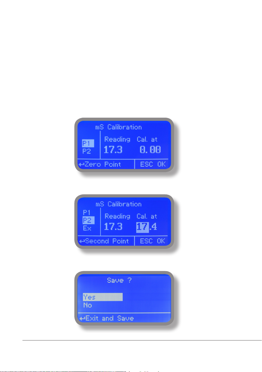
9.1 “Menu Calibration”, Probe CD
Conductivity calibration procedure involves a zero calibration (P1) and a 2nd calibration point (P2) that requires a
buffer solution with value near working range. Note: This procedure assumes that instrument is correctly installed
and congured, connected to a working probe. Calibrate using plant’s temperature otherwise unattended
results may occur. Verify probe selection into “MENU CALIBRATION”, “SELECT PROBE” pag. 15 before to start
calibration procedure.
P1 & P2
During this procedure probe must be dry and clean and not installed in plant. Move wheel on “P1” then press wheel,
move cursor on “OK” and press wheel again. Move wheel on “P2” then press wheel to enter into second point calibration
submenu. Prepare buffer solution and dip probe’s sensor on it. Wait until reading value is stable and according to buffer
solution value move wheel until it is the same on display (“uS default” eld). End procedure moving cursor on “OK”.
14
Page 15
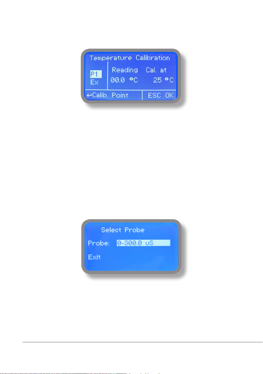
9.1 “Probe Calibration”, °C - Temperature
A professioanl thermometer is required to obtain a reliable calibration. From “Menu Calibration” choose “Temp probe”.
Note: This procedure assumes that instrument is correctly installed and congured, connected to a working
PT100.. Calibrate using plant’s temperature otherwise unattended results may occur.
Using an external thermometer read actual temperature and edit related eld “Cal. at”. Conrm by pressing wheel.
9.2 “Menu Calibration”, Scale Setup
Instrument can operate according to uS, mS or PPM reading values and scale range. Move cursor on “Probe” press and
rotate the wheel to change it within 3000uS --> 30.00mS --> 300.0mS or PPM (K1, K 0.1, K10).
Special x1000 scale version can be set choosing “SALINITY” as probe’s model name.
Note: these changes must be set according to probe reading capacity. See probe’s datasheet to choose correct values.
15
Page 16
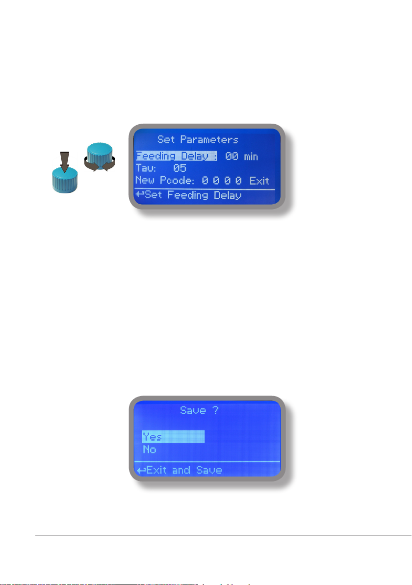
10. “Parameters”
From “Menu Calibration” choose “Parameters”. This menu allows to set a delay (max 60 minutes) before pumps begin
to feed. Furthermore use this menu to set pH pump startup priority and to change default passcode.
Feeding Delay.
Move on “Feeding Delay” then press wheel. Choose a value between 0 (disabled) and 60 minutes (maximum delay
time). This feature can be used to accord a startup delay for the pumps. Delay occurs when instrument is powered.
Mode.
Move on “Mode” then press wheel. If both pumps need to operate, a startup priority can be set to allow the pH pump to
begin to feed prior to Cl pump. Choose “pH priority” to enable this function. Cl pump will begin to dose when pH pump
has stopped.
Tau.
If probes reading values are changing too fast increase TAU value to stabilize them. Default value is 05. Maximum
value is 30.
New Pcode.
See page 10.
To end procedure move cursor on “OK” and press wheel to proceed to “Save” request screen. Move wheel on “YES” to
save or “NO” to discard changes.
16
Page 17
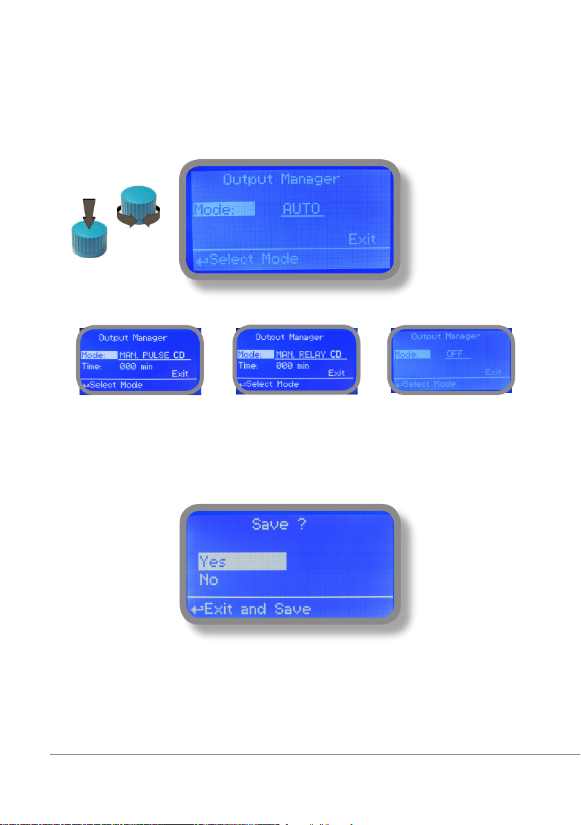
11. “Output Manager”
From “Menu Calibration” choose “Output Manager”. This menu allows to manually operate all outputs for a
settable time. Set to “AUTO” for normal operating mode. Set to “OFF” to permanently disable outputs.
Press wheel to move cursor on “TIME” field. Once here, choose a working time between 0 (disabled) or 199
minutes. Move on “EXIT”, then press wheel.
Choose “YES” to save changes. Exit from main menu. Main display will show a countdown for selected output.
To stop this countdown go back to “Output Manager” menu and choose “AUTO” as working mode or wait until
countdown ends. This function can be used for priming purposes.
17
Page 18
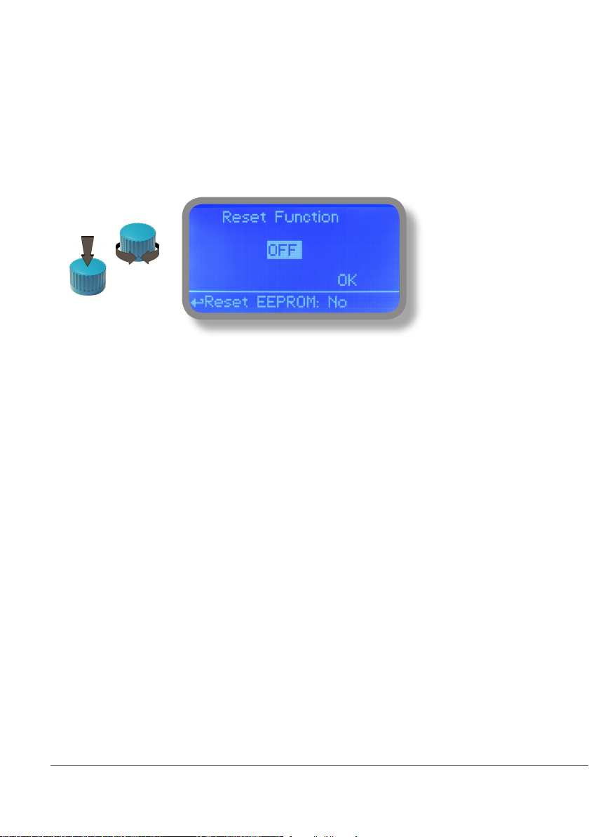
12. “Instrument Reset”
To restore instrument to its default values (including password) once into “Instrument Reset” menu, press wheel
then change value to “ON”, press wheel again, move on “OK” then finally press wheel. The instrument display
will show “CHECKSUM ERROR”. Press whell to return into “Main Menu”. Move on “EXIT”, then press wheel. The
instrument is now restored to factory default. Please repeat all calibration procedures and programming parameters.
18
Page 19
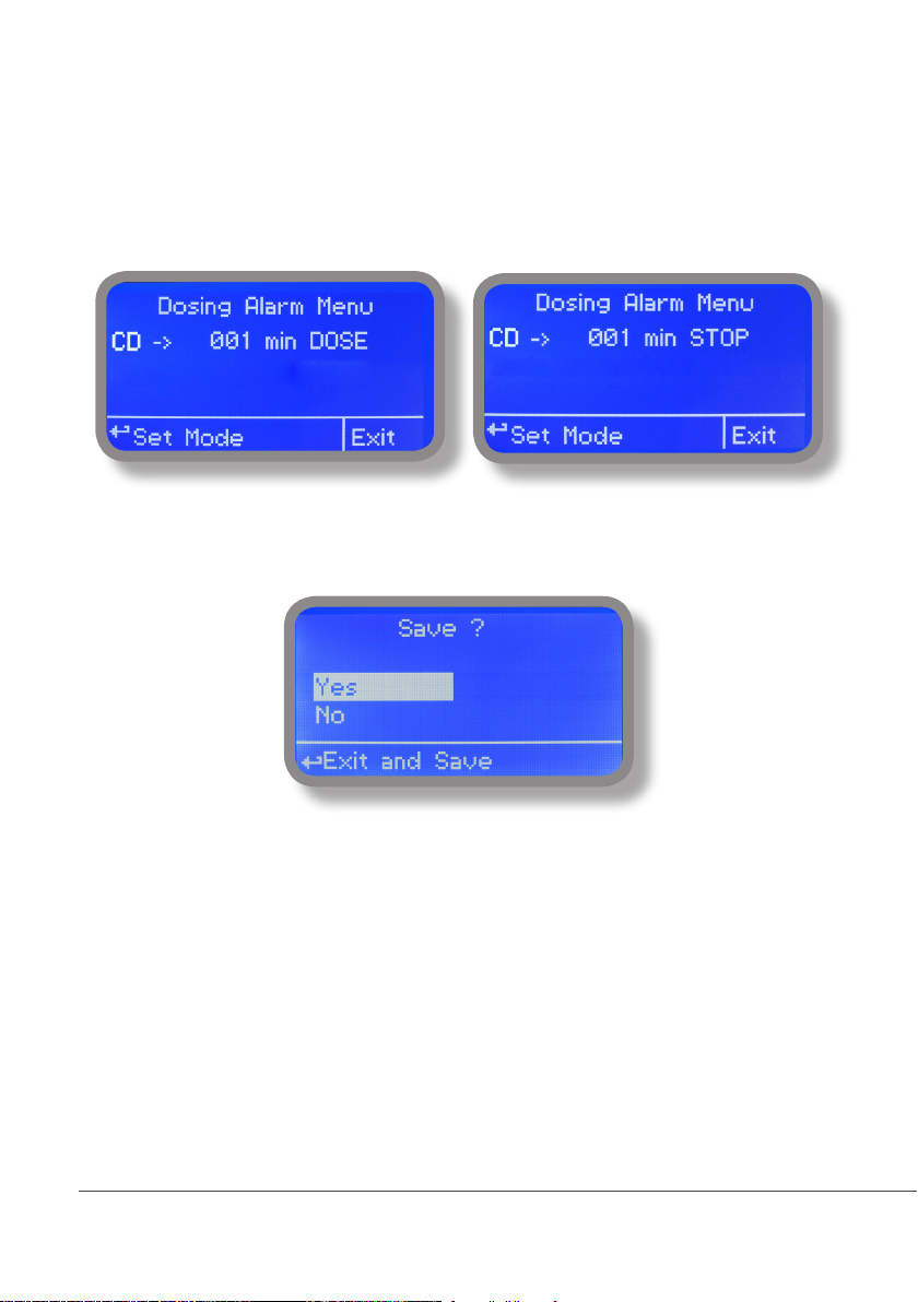
13. “Dosing Alarm”
Use this menu to assign a maximum time to the pumps for reaching the setpoint. If set time ends and the pumps
are still dosing, within this menu is possible to STOP them or just to show an alarm message. Function can be
disabled selecting “OFF” instead of a number (minutes). Dosing alarm can be set for both or just one pump.
E.g. To set Conductivity pump to stop after time ends and setpoint isn’t still reached press wheel, choose maximum
time, press wheel move on next field and choose “STOP”. Time can be set between 0 and 100 minutes. When
satisfied with settings move on exit and press wheel.
To end procedure move cursor on “OK” and press wheel to proceed to “Save” request screen. Move wheel on “YES”
to save or “NO” to discard changes.
19
Page 20
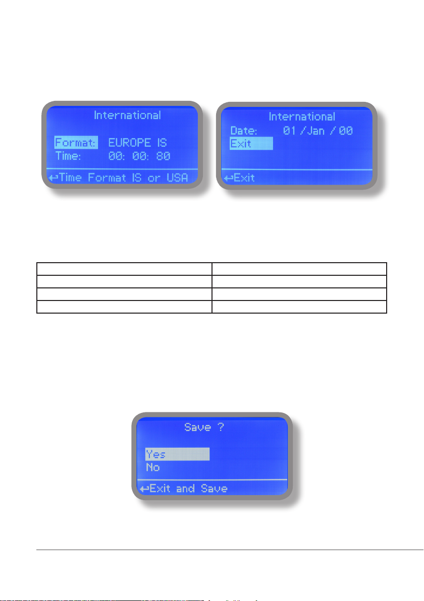
14. “International”
Use this menu to set international parameters as UNIT FORMAT (Europe IS or USA), Local Time and Date.
Format.
Use this option to use European or USA units format. See table for differencies.
EUROPE IS (Internationl Standard) USA
Date (DD/MMM/YY) Date (MMM/DD/YY)
Time 24h Time AM / PM
°C °F
Time.
Use this option to set local time.
Date.
Use this option to set date.
Move on exit to end changes.
To end procedure move cursor on “OK” and press wheel to proceed to “Save” request screen. Move wheel on
“YES” to save or “NO” to discard changes.
20
Page 21
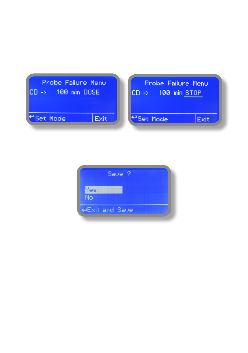
15. “Probe Failure”
Use this menu to assign a maximum time for connected probes to stay in “stuck” condition. A stuck probe (it
remains on same reading value for some time) means that probably probe itself is damaged. Within this menu
is possible to STOP pumps or just to show an alarm message (probe failure) . Function can be disabled selecting
“OFF” instead of a number (minutes). This function can be set for both or just one probe.
E.g. To set CD pump to stop after time ends and probe doesn’t change reading values press wheel, choose maximum time, press wheel move on next field and choose “STOP”. Time can be set between 100 and 254 minutes.
When satisfied with settings move on exit and press wheel.
To end procedure move cursor on “OK” and press wheel to proceed to “Save” request screen. Move wheel on “YES”
to save or “NO” to discard changes.
21
Page 22
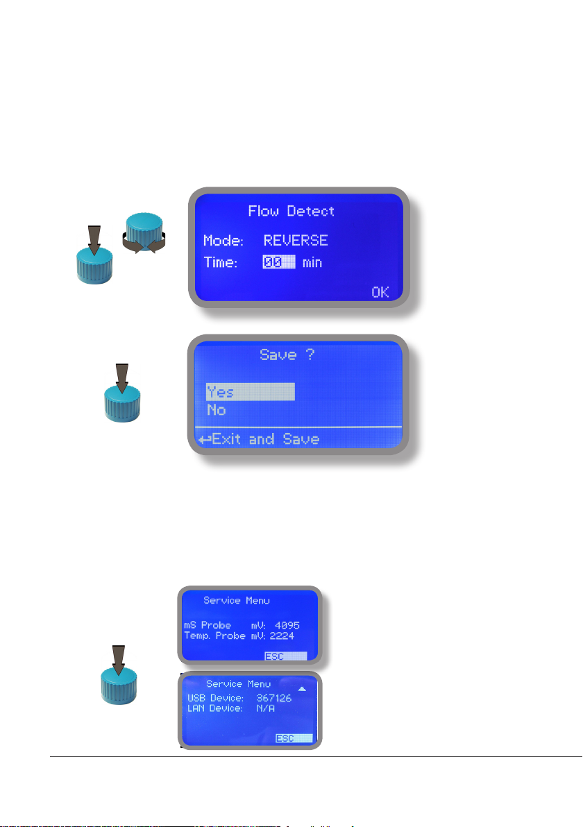
16. “Flow Contact”
Flow contact (see “SEPR” blocks on page 4) can be enabled to stop a dosing procedure using a N.O. contact mode
(normally open) or N.C. contact mode (normally closed) when status on blocks changes. Rotate wheel to choose
between: “DISABLE”, “REVERSE” (N.O. contact) or “DIRECT” (N.C. contact).
Furthermore “Flow contact” can starts after a specified time when contact status changes. To set it move wheel on
“Time:00 min”, click it and rotate to choose time (from 0 to 99 minutes). Confirm selection by clicking wheel.
To end procedure move cursor on “OK” and press wheel to proceed to “Save” request screen. Move wheel on
“YES” to save or “NO” to discard changes.
17. “Service”
This “view only” menu shows probes reading live and instrument ID for USB LOG connection (if device’s connected). Press “ESC” to exit.
Connection Code for ERMES (through USB cable)
Connection Code for ERMES (through LAN cable)
22
Page 23
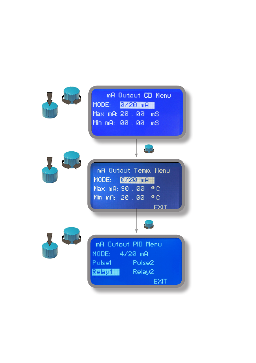
18. “mA Outputs”
This menu allows to configure mA current otputs for Conductivity, Temperature channels and PID mA mode. Options
to set are:
MODE (selectable between 0-20 or 4-20 mA current output)
Max mA: maximum probe’s reading value at 20 mA current
Min mA: minimum probe’s reading value at 0 or 4 mA current
Disable / Enable on alarm: enable or disable output on alarm condition (flow, level, probe failure, dosage, out of range)
Note: The outputs available for the PID mA are those set in the menu SETPOINT.
PID outputs will be always disbled during an alarm condition
Rotate wheel to move within all 3 channels. Click wheel to selecte parameter and rotate wheel to change it. Click
wheel again and rotate wheel to move cursor on next parameter.To end procedure move cursor on “EXIT” and press
wheel to proceed to “Save” request screen. Move wheel on “YES” to save or “NO” to discard changes.
23
Page 24
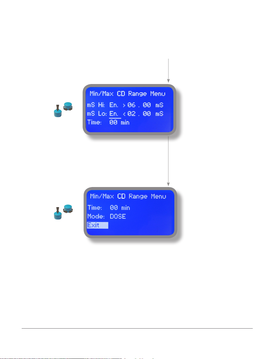
19. “Out of range alarm”
“Out of range alarm” menu defines the minimum and maximum Conductivity probe read value before to stop dosing
activity and to show an alarm message.
Move wheel on “Min/Max mS Range” to set
“out of range” condition for Conductivity
probe then click on wheel to enter into
“Min/Max Range menu”.
Move wheel on “mS Hi: Dis.” and change
status from “Dis.” (option disabled) to “En.”
(option enabled) by clicking on wheel and
rotating it. Press wheel again and move on
next field. Press wheel and enter a value for
HIGH alarm.
Repeat procedure for “mS Lo: Dis.” and
enter a value for LOW alarm.
As last option enter “Time” (max 99
minutes) after which if lower or higher read
value condition stays then the alarm occurs
(to set into mode field).
To change alarm mode move wheel on
“Mode”, press it and choose between
“DOSE” (connected pumps will not stop
dosing activity when read value is out
of range) or “STOP” (connected pumps
will stop dosing activity when read value
is out of range and an alarm message is
displayed).
24
Page 25
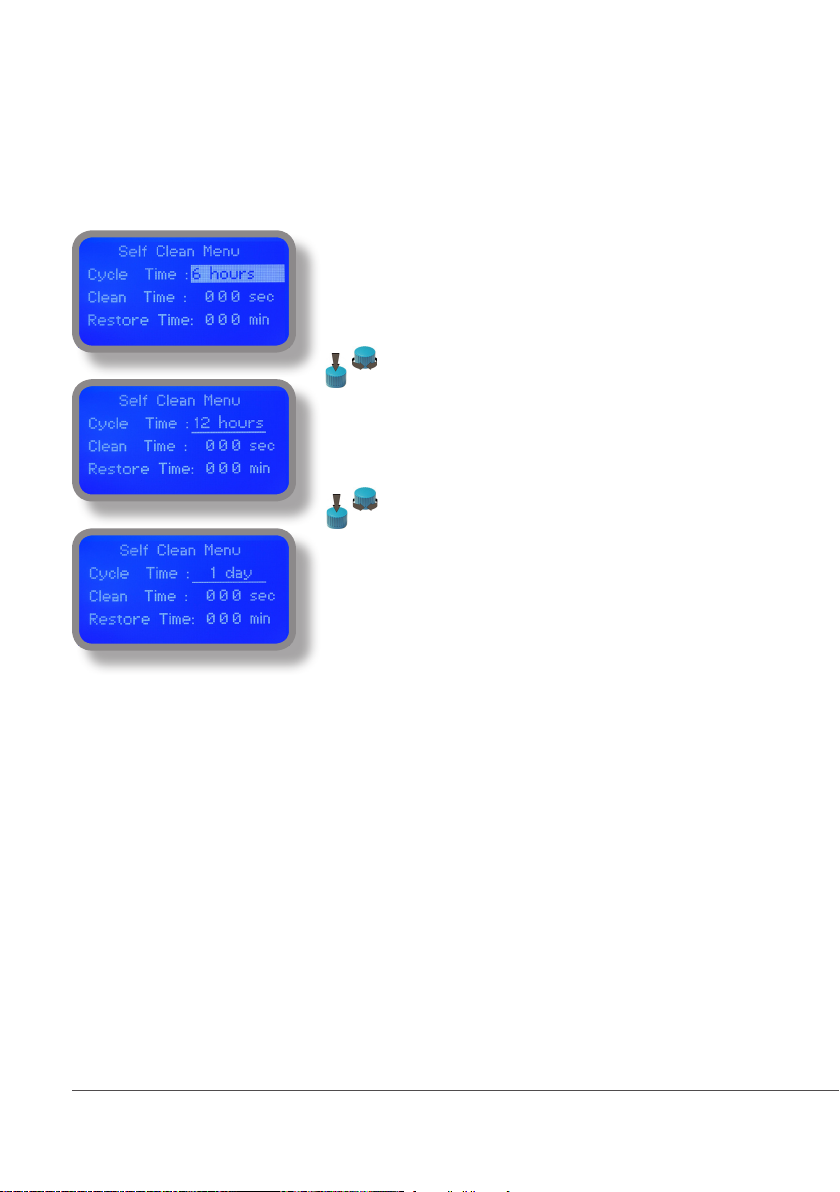
20. “Self Clean”
To obtain reliable results, the instrument can be connected to a cleaning apparatus (eg .: Probe Cleaning). This menu
enables the functionality to blocks 4-E-N (see page 8).
Options are:
Cycle Time: time between cleaning procedure and next
procedure (adjustable from 6 hours to 10 days)
Clean Time: time required to complete probe cleaning
procedure (adjustable from 0 to 999 seconds)
Restore Time: time to wait after cleaning to restore probe
reading functionalities (adjustable from 0 to 999 minutes)
Clean on Alarm: Threshold alarm before to start procedure
(out of range alarm)
To find optimal values refers to probe manufacturer.
25
Page 26
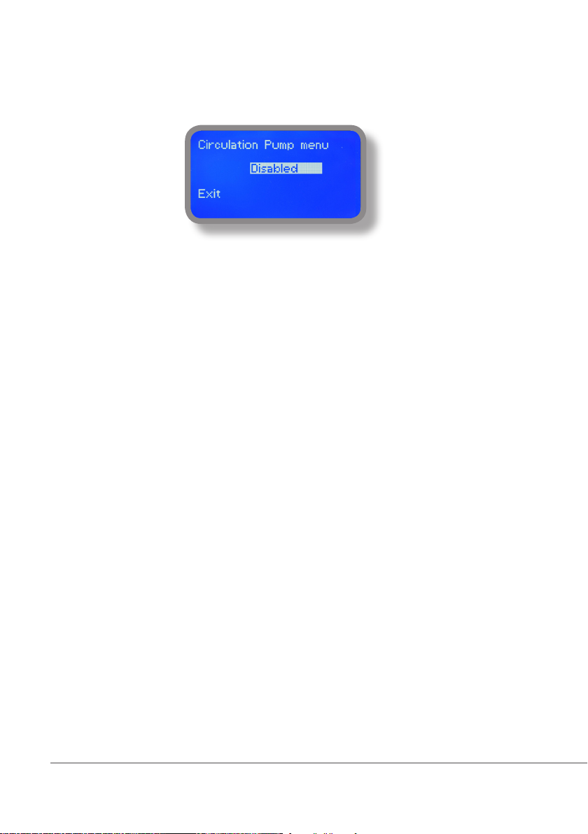
21. “Circulator Pump”
This feature allows you to power a pump for water circulation inside the intake pipeline, increasing the pressure.
To activate the circulation pump connected to terminals 5-E-N (see terminal) set option to “ENABLED” To disable set
the tool to “DISABLED”.
26
Page 27

22. Technical information.
Conductivity range: 0-3000uS ; 0-30.00mS ; 0-300.0mS ; K1 ppm ; K0.1 ppm ; K10 ppm
Power supply: 85÷264 VAC
Environment Temperature: -10 ÷ 45°C (14 ÷ 113°F)
Chemical Temperature: 0 ÷ 50°C (32 ÷ 122°F)
Installation Class: II
Pollution Level: 2
Packaging and Transporting Temperature: -10 ÷ 50°C (14 ÷ 122°F)
Protection degree: IP 65
Product Formula Ceram. PVDF PP PVC SS 316 PMMA Hastel. PTFE FPM EPDM NBR PE
Acetic Acid, Max 75% CH3COOH 2 1 1 1 1 3 1 1 3 1 3 1
Hydrochloric Acid, Concentrate HCl 1 1 1 1 3 1 1 1 1 3 3 1
Hydrouoric Acid 40% H2F2 3 1 3 2 3 3 2 1 1 3 3 1
Phosphoric Acid, 50% H3PO4 1 1 1 1 2 1 1 1 1 1 3 1
Nitric Acid, 65% HNO3 1 1 2 3 2 3 1 1 1 3 3 2
Sulphuric Acid, 85% H2SO4 1 1 1 1 2 3 1 1 1 3 3 1
Sulphuric Acid, 98.5% H2SO4 1 1 3 3 3 3 1 1 1 3 3 3
Amines R-NH2 1 2 1 3 1 - 1 1 3 2 3 1
Sodium Bisulphite NaHSO3 1 1 1 1 2 1 1 1 1 1 1 1
Sodium Carbonate (Soda) Na2CO3 2 1 1 1 1 1 1 1 2 1 1 1
Ferric Chloride FeCl3 1 1 1 1 3 1 1 1 1 1 1 1
Calcium Hydroxide (Slaked Lime) Ca(OH)2 1 1 1 1 1 1 1 1 1 1 1 1
Sodium Hydroxide (Caustic Soda) NaOH 2 1 1 1 1 1 1 1 2 1 2 1
Calcium Hypochlor.(Chlor.ted Lime) Ca(OCl)2 1 1 1 1 3 1 1 1 1 1 3 1
Sodium Hypochlorite, 12.5% NaOCl + NaCl 1 1 2 1 3 1 1 1 1 1 2 2
Potassium Permanganate, 10% KMnO4 1 1 1 1 1 1 1 1 1 1 3 1
Hydrogen Peroxide, 30% (Perydrol) H2O2 1 1 1 1 1 3 1 1 1 2 3 1
Aluminium Sulphate Al2(SO4)3 1 1 1 1 1 1 1 1 1 1 1 1
Copper-II-Sulphate (Roman Vitriol) CuSO4 1 1 1 1 1 1 1 1 1 1 1 1
Resistance rating: (1: Resistant) ; (2: Fairly resistant) ; (3: Not resistant)
Polyvinyldene uoride (PVDF) Pump Heads, valves, fitting, tubing
Polypropylene (PP) Pump Heads, valves, fitting, level floater
PVC Pump Heads
Stainless steel (SS 316) Pump Heads, valves
Polymethyl Metacrilate (Acrylic) PMMA Pump Heads
Hastelloy C-276 Injection valve spring
Polytetrauoroethylene (PTFE) Diaphragm
Fluorocarbon (Viton® B) Sealings
Ethylene propylene (EPDM) Sealings
Nitrile (NBR) Sealings
Polyethylene (PE) Tubing
27
Page 28
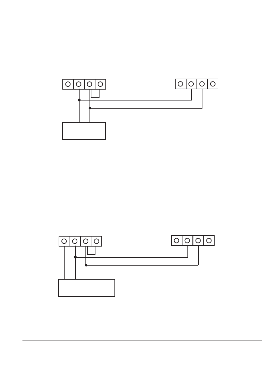
23. SEPR configuration
SEPR “Flow Sensor” configuration for two instruments
14 15 16 17
black
brown
blue
14 15 16 17
SEPR
Configuration of a Flow Switch with a voltage free contact and two instruments
14 15 16 17
14 15 16 17
black
brown
N.C. contact (OK)
N.O. contact (Alarm)
NPED4
28
blue
Page 29
24. “Water Meter”
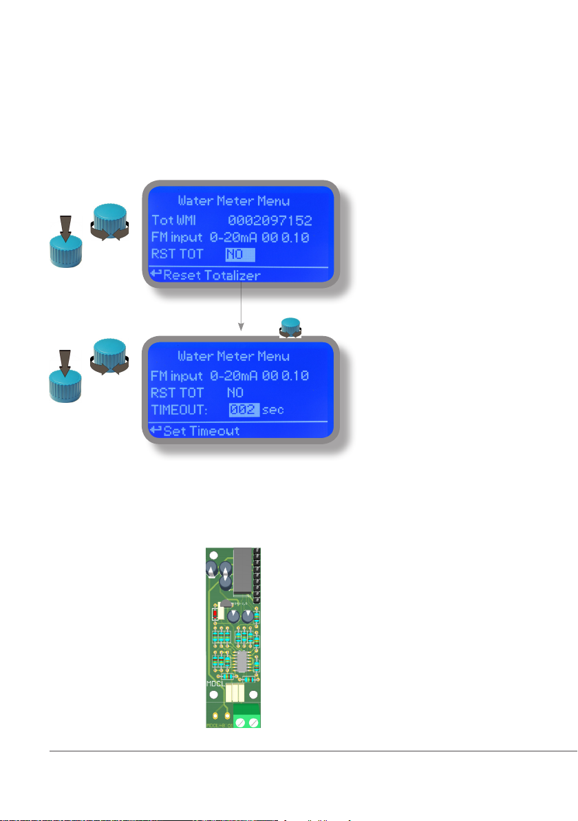
Enter into “Water Meter” menu to setup Flow Meter configuration type, see total amount of liters passed through
water meter, reset totalizer and setup a timeout alarm for no water flow. The alarm will be notified into main screen
and water meter status (see page 6).
Tot WMI: water passed through water meter
FM Input: Water Meter Working Mode
RST TOT: reset totalizer
Timeout: countdown to “no water flow alarm”
FM Input can be set to operate Water Meter as 0-20mA or 4-20mA input, P/L (pulses per liter) or L/P (liters per pulse).
Connect as follows using mA working mode:
Block 1 : red wire (+)
Block 2 : black wire (-)
1 2
29
Page 30
25 “Feed Forward”, PID loop
The PID controller algorithm involves three separate constant parameters, and is accordingly sometimes called threeterm control: the proportional, the integral and derivative values, denoted P, I, and D. Simply put, these values can be
interpreted in terms of time: P depends on the present error, I on the accumulation of past errors, and D is a prediction
of future errors, based on current rate of change. The weighted sum of these three actions is used to adjust the process
via a control element such as the position of a control valve, a damper, or the power supplied to a heating element.
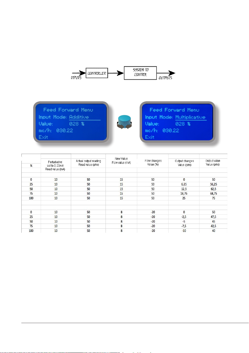
This function manages all instrument outputs based on changes read by mA input and multiply value referring to % and
mc/h read by the module.
30
Page 31
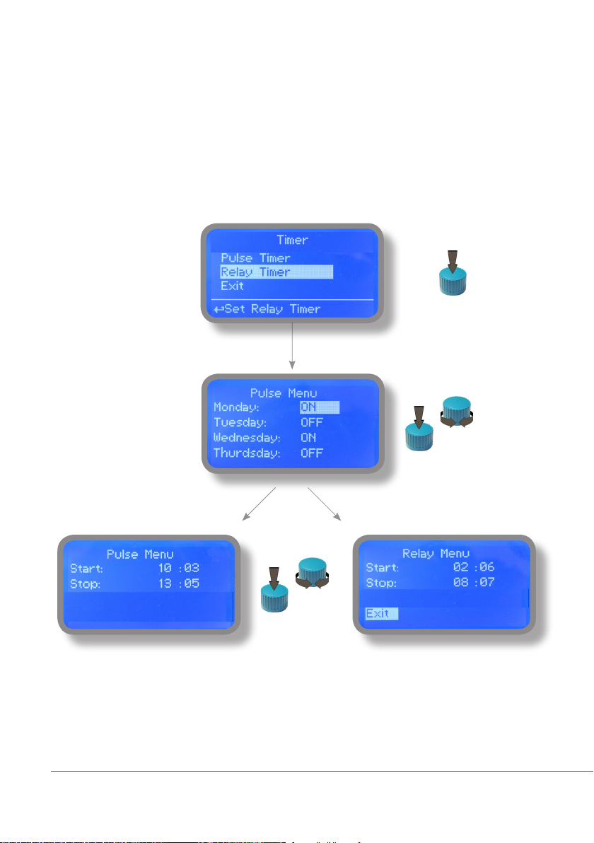
26. LDSCDIND PLUS D Version
The LDSCDIND PLUS D has two timered outputs that are always off until the value reaches the set time. An extra
menu is available under main settings.
1(Live) - E(Earth) - N(Neutral): 85÷264VAC - 5A 50/60 Hz Relay Output “CD Relay Timer”. To use with ON/OFF or PWM device
26(-) - 27(+): Opto coupled output “CD PULSE Timer”. To use with “IS” , “MF” , “PLUS” series dosing pumps
To activate this function operator must specify starting / ending time, day of the week, target setpoint, pulses per minute
for attached pump (pulses output only). Operation will end at ending time. This function override normal instrument
activities. Normal operations will resume at the ending of procedure and feeding delay timer set in “PARAMETERS”
menu (see page 22).
“CD Pulse Timer”
26(-) - 27(+)
“CD Relay Timer”
1- E- N
To activate this function operator must specify starting / ending time, day of the week, target setpoint, pulses per minute
for connected pump (pulses output only).
31
Page 32
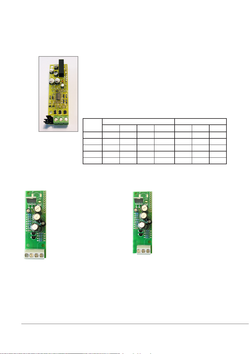
Appendix - Conductivity module MDCD
Setup connections according to probe features.
MDIND
1 2 3 4
Connect probe as follows:
Block n.1 : Shield
Block n.2 : Black (probe)
Block n.3 : Red (probe)
Extra wires for EICDHPTI on mainboard:
6(Green) - 7(Brown)
8(White) - 9(Yellow)
1 2 3
J5
J4
J3
MDCD
8 WIRES CABLE:
4 PROBE WIRES
4 PT100 WIRES
Connect 4 probe wires to MDIND module as follow:
Block n. 1 : blue
Block n. 2 : black
Block n. 3 : grey
Block n .4 : red
Connect 4 PT100 wires to mainboard (ref. p. 4) as follow:
Block n. 6 : green
Block n. 7 : orange or pink
Block n. 8 : white
Block n. 9 : yellow
Instrument
scale
0 - 300.0 uS 0.1 ECDHL/01 x ECDI/01 OPEN CLOSED CLOSED
0 - 3000 uS 1 ECDHL/1 ECDC/1 ECDI/1 OPEN CLOSED OPEN
0 - 30.00 mS 1 ECDHL/1 ECDC/1 x CLOSED OPEN OPEN
0 - 30.00 mS 10 ECDHL/10 ECDC/10 x OPEN OPEN OPEN
0 - 300.0 mS 10 ECDHL/10 ECDC/10 x CLOSED OPEN OPEN
Connect ECDHL PT100 extra wires to
mainboard as follows:
Block n. 6 + 7: white
Block n. 8 + 9: green
PROBE MODEL JUMPERS SETTING
K PlatinUM Graphite Stainless Steel J3 J4 J5
MDECDSIND
ECDS IND PT PROBE
Connect 4 probe wires to MDIND module as follow:
Block n.1 : blue
Block n.2 : green
Block n.3 : red
Connect 4 PT100 wires to mainboard (ref. p. 5)
as follow:
Block n. 6 + 7: white
Block n. 8 + 9 : black
1 2 3
32
Page 33
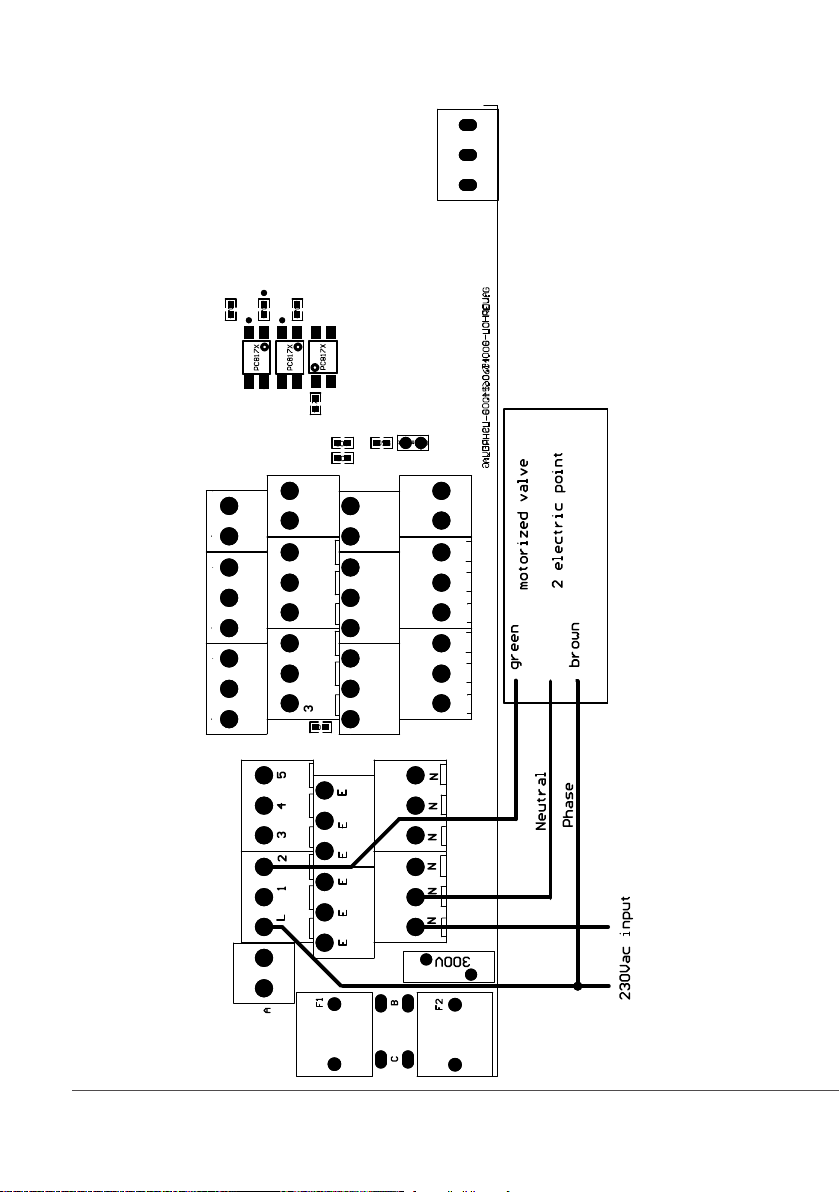
Appendix -Electrovalve connections
blue
33
Page 34
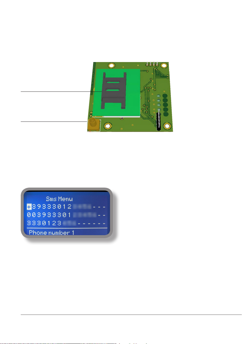
Appendix Communication HARDWARE - “SMS/GSM” Module
Located under mainboard cover there is a four pins connector that can be used to install USB, ETHERNET or MODEM
modules. Modules come pre-installed upon request and may appear different as shown (different configurations).
“SMS/GMS module” can be congured to send SMS messages containing critical instrument information.
Insert here standard
SIM
Unplug instrument
from main supply
before to open it.
GSM modem antenna connector
To obtain reliable results with this feature please check the following list:
- Make certain the antenna location is not shielded by metal objects or near sources of electrical ‘noise’.
- Do not route the cable where it could be pinched in doors, windows etc.
- Secure the antenna cable
- Ensure that SIM into “SMS/GSM modeule” is properly inserted, activated and within operator range.
- Set instrument ID / NAME from “RS485 Setup” menu and configure “Out of Range Alarm” menu.
Within “Main menu” select “SMS MENU” to enable SMS service and enter SMS receiver phone numbers.
Up to three numbers for sending SMS can be stored
into LDSCD memory. SMS recipient will receive an
SMS containing instrument ID, NAME and status.
Number formats can be stored using international
prefix “+”, international prefix “00” or local.
WARNING: THIS FUNCTION COULD NOT BE
FREE OF CHARGE. DEPENDING ON YOUR OPERATOR CONTRACT IT
COULD GENERATE PAYING SMS TRAFFIC !
34
To enable warning message for related alarm
condition choose “YES”, to disable choose “NO”.
Then move wheel on Exit and SAVE configuration.
SMS will be sent when one or more (“YES”) elds
will change.
E.g.:
LCD1 or 2 : level alarm for PH1 or PH2 levels
LCD: level alarm for Conductivity
FLOW: flow alarm
ALCL: out of reading range for Conductivity probe
WARNING: TO AVOID UNDESIRED MESSAGES USE CAREFULLY THIS
SETUP!
Page 35
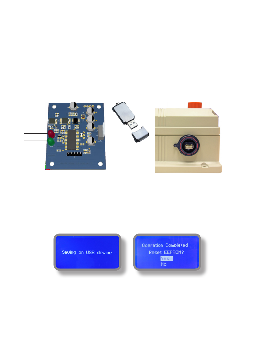
Appendix Communication HARDWARE - “LOG USB” Module
Located under mainboard cover there is a four pins connector that can be used to install “USB data log module”
or “SMS module”. Modules come pre-installed upon request and may appear different as shown (different
configurations).
“USB data log module” records instrument activities. These information can be permanently stored into a standard
USB pendrive. Pendrive can be connected to a PC using “ERMES” web www.ermes-server.com to review and print
instrument’s activities. To obtain reliable results with this feature please set instrument ID and NAME from
“RS485 Setup” menu and activate log recording from “LOG SETUP” menu.
Activity LED
Power LED
Standard USB pendrive
(not included)
Insert USB pendrive here
(right side of instrument)
After usage put back USB cap
HOW TO RECORD INSTRUMENT’S ACTIVITIES INTO USB PENDRIVE ?
Insert USB pendrive into USB connector (located on the right side of instrument). Instrument will save data log on
USB pendrive. After succeded in saving data it will ask if delete instrument’s log or not (anyway USB pendrive will
not be formatted). Move wheel on “YES” to delete log info from instrument and return to main screen or “NO”
to leave log info on instrument and return to main screen. Wait about 30 seconds to safety remove the USB
pendrive.
HOW TO REVIEW INSTRUMENT’S ACTIVITIES RECORDED INTO USB PENDRIVE ?
It’s necessary to connect to web “ERMES” www.ermes-server.com to review USB pendrive info on a PC.
35
Page 36
Appendix Communication - Software
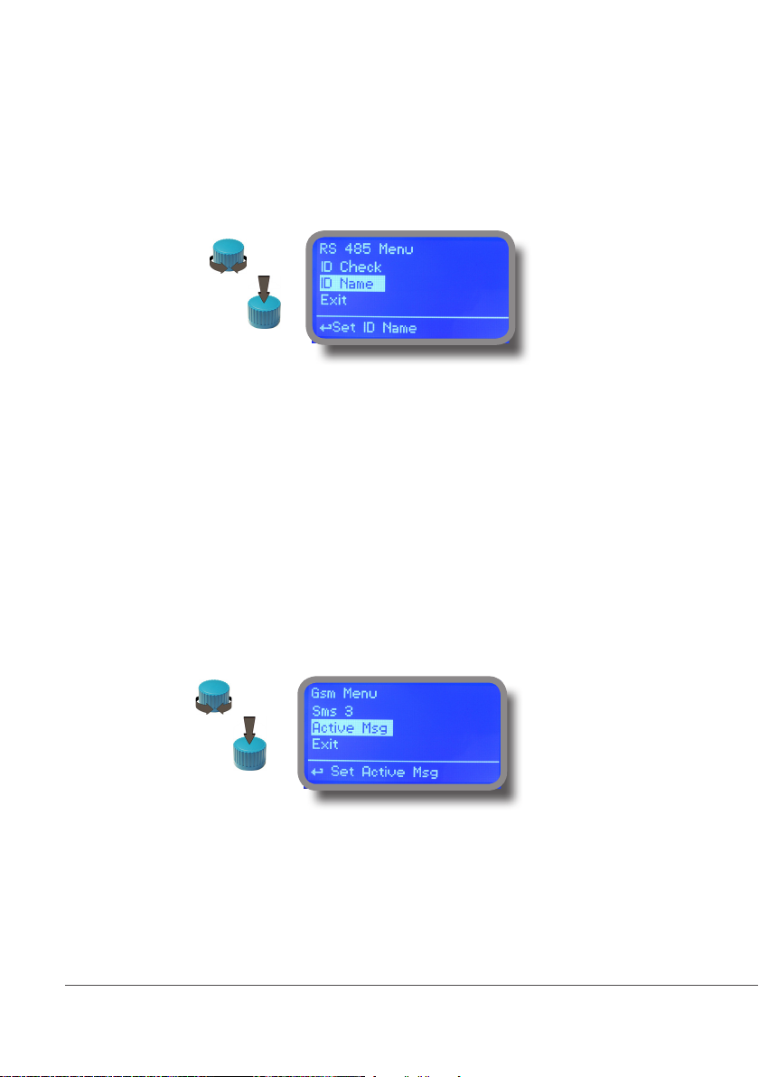
“RS485” menu.
Prior to install the instrument into an RS485 local system a unique ID NUMBER (from 1 to 30) and ID NAME (station
name) must be set. Rotate wheel and edit elds. If ID number has already assigned an error message will follow after ID
Check (move cursor on CHECK and press wheel). In this event try using another number.
Choose
Edit
“SMS” menu.
Instrument may remotely send SMS alarm messages using its own modem (sold as option). It can be congured as
follows:
SMS1 / SMS2 /SMS3.
Using the wheel enter a mobile phone that will receive alert SMS messages if something wrong occurrs. SMS number
must be set using local number format. For example : 3391349134 will send an SMS message to mobile phone.
Log level (and SMS frequency alert) may be set using options in “ACTIVE MSG” within “GSM menu”.
Choose
Edit
- TO AVOID UNDESIRED MESSAGES USE CAREFULLY LOG SETUP -
- WARNING: THIS FUNCTION COULD NOT BE FREE OF CHARGE. DEPENDING ON YOUR OPERATOR CONTRACT IT
COULD GENERATE PAYING SMS TRAFFIC !
36
Page 37
Appendix Communication - Software
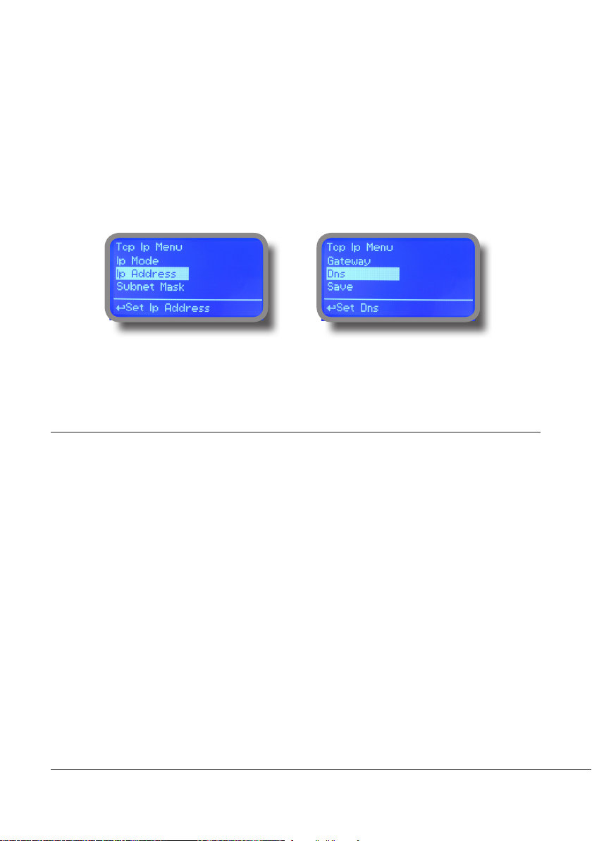
“TCP/IP” menu.
The instrument may be remotely operated using a standard ethernet connection (sold as option). A static or dynamic IP
address and a CAT5 ethernet cable is required. According to your network capacity connection speed is 10/100Mbps.
To obtain a valid IP address and subnet mask contact your net administrator. Enter parameters and move cursor on
“SAVE” to store parameters then move on “OK” and press wheel to save and activate conguration.
Based on your network conguration choose to obtain network parameters automatically (DYNAMIC) or manually
(STATIC).
See “ERMES Communication Software” manual for proper PC software conguration.
What is a static IP address/dynamic IP address?
A static IP address is a number (in the form of a dotted quad) that is assigned to a computer by an Internet service provider (ISP)
to be its permanent address on the Internet. Computers use IP addresses to locate and talk to each other on the Internet, much the
same way people use phone numbers to locate and talk to one another on the telephone. When you want to visit whatis.com, your
computer asks a domain name system (DNS) server (think telephone information operator) for the correct dotted quad number
(think phone number) for whatis.com and your computer uses the answer it receives to connect to the whatis.com server.
It would be simple if every computer that connects to the Internet could have its own static IP number, but when the Internet was
rst conceived, the architects didn’t foresee the need for an unlimited number of IP addresses. Consequently, there are not enough
IP numbers to go around. To get around that problem, many Internet service providers limit the number of static IP addresses
they allocate, and economize on the remaining number of IP addresses they possess by temporarily assigning an IP address to
a requesting Dynamic Host Conguration Protocol (DHCP) computer from a pool of IP addresses. The temporary IP address is
called a dynamic IP address.
Requesting DHCP computers receive a dynamic IP address (think temporary phone number) for the duration of that Internet ses-
sion or for some other specied amount of time. Once the user disconnects from the Internet, their dynamic IP address goes back
into the IP address pool so it can be assigned to another user. Even if the user reconnects immediately, odds are they will not be
assigned the same IP address from the pool. To keep our telephone telephone analogy going, using a dynamic IP address is similar to using a pay phone. Unless there is a reason to receive a call, the user does not care what number he or she is calling from.
There are times, however, when users who connect to the Internet using dynamic IP wish to allow other computers to locate them.
Perhaps they want to use CU-SeeMe or use a VoIP application to make long distance phone calls using their IP connection. In that
case, they would need a static IP address. The user has two choices; they can contact their ISP and request a static IP address, or
they can use a dynamic DNS service. Either choice will probably involve an additional monthly fee.
Using a dynamic DNS service works as if there was an old-fashioned telephone message service at your computer’s disposal.
When a user registers with a DNS service and connects to the Internet with a dynamic IP address, the user’s computer contacts
the DNS service and lets them know what IP address it has been assigned from the pool; the service works with the DNS server
to forward the correct address to the requesting DHCP computer. (Think of calling the message service and saying “Hi. I can be
reached at 435.44.32.111 right now. Please tell anyone who tries to reach me to call that number.) Using a dynamic DNS service to
arrange for computers to nd you even though you are using a dynamic IP address is the next-best thing to having a static IP.
37
Page 38
Appendix Communication - Software
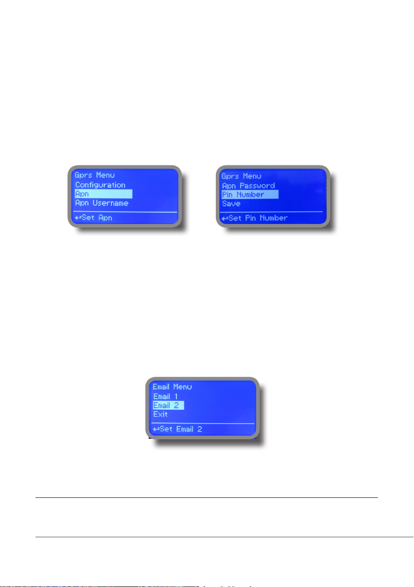
“GPRS” menu.
Instrument may be remotely operated using an embedded standard GPRS modem (sold as option). In order to activate
this service please ensure that the following steps are correctly completed:
- Make certain the antenna location is not shielded by metal objects or near sources of electrical ‘noise’.
- Make certain the distance from the antenna to the “Instrument” unit is within cable length.
- Do not route the cable where it could be pinched in doors, windows etc.
- Ensure that SIM into “Instrument” modem is correctly inserted, activated and within operator range.
Instrument can be set for ERMES services enabled (Conguration option set to “ERMES YES”) or messages only
(Conguration option set to “ERMES NO”) based on your SIM data access parameters. For manual conguration option
enter APN (access point name) and SIM phone number. Move wheel on “OK” to save and move on “ESC” to go back to
main menu.
WARNING: THIS FUNCTION COULD NOT BE FREE OF CHARGE. DEPENDING ON YOUR OPERATOR CONTRACT IT
Don’t forget to enter SIM CODE into PIN NUMBER menu to unlock SIM.
COULD GENERATE PAYING DATA TRAFFIC !
“Email” menu.
If Ethernet module or GPRS module is installed (sold as option) the instrument can be congured to send email alarm
messages up to two recipients. Click on “Email 1” or “Email 2” and enter email address.
Access point name (APN) identies an IP packet data network (PDN), that a mobile data user wants to communicate with. In addition to identifying a PDN, an
APN may also be used to dene the type of service, (eg connection to wireless application protocol (WAP) server, multimedia messaging service (MMS)), that
is provided by the PDN. APN is used in 3GPP data access networks, eg general packet radio service (GPRS), evolved packet core (EPC).
38
Page 39
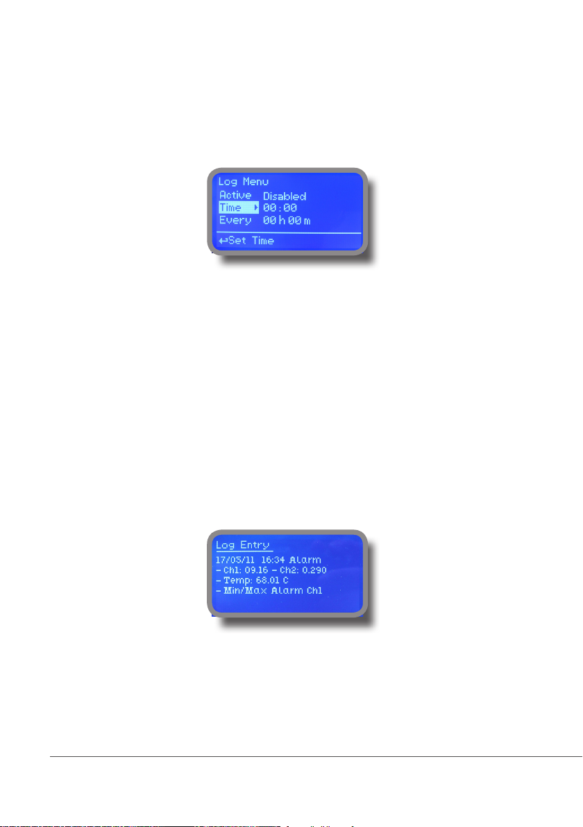
Appendix Communication - Software
“LOG” menu.
This function records instrument acitvity (date, hour, temperature, uS, totalizer I/O, alarms, outputs). It starts for
selected frequency period (every) at requested time (time). SET DATE & TIME BEFORE TO ENABLE LOG. IF NOT
POWERED FOR ABOUT 30 DAYS THE INSTRUMENT WILL LOOSE DATE/TIME
Set ACTIVE to “enabled” to activate log recording.
TIME: recording start time (time format 23h e 59min)
EVERY: recording frequency (time format 23h e 59min)
Note: advanced log control (graph, printing, comparison tables, event ltering, etc) is available through “ERMES
Communication Software” for PC.
See “ERMES Communication Software” manual for proper PC software conguration.
“LOG VIEW” menu.
To see alarrm log entries as set on log menu choose “log view” on main menu.
39
Page 40
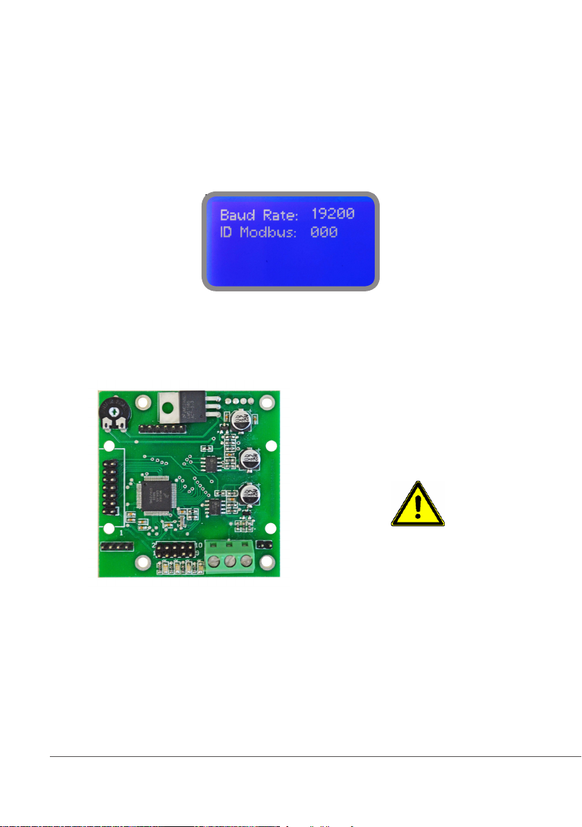
Appendix - MODBUS
Modbus is a serial communications protocol originally published by Modicon (now Schneider Electric) in 1979 for
use with its programmable logic controllers (PLCs). Simple and robust, it has since become a de facto standard
communication protocol, and it is now a commonly available means of connecting industrial electronic devices.
From main menu select COMMUNICATION then MODBUS to access the options. Set the communication speed
according to the PLC system available. Set the ID assigning an UNIQUE address to avoid conflicts.
To access the module MODBUS open the instrument only after power is switched off!
Never make connections with the instrument powered!
WARNING
1 2 3
1: GND
2: A-RS485 (+)
3: B-RS485 (-)
40
Page 41
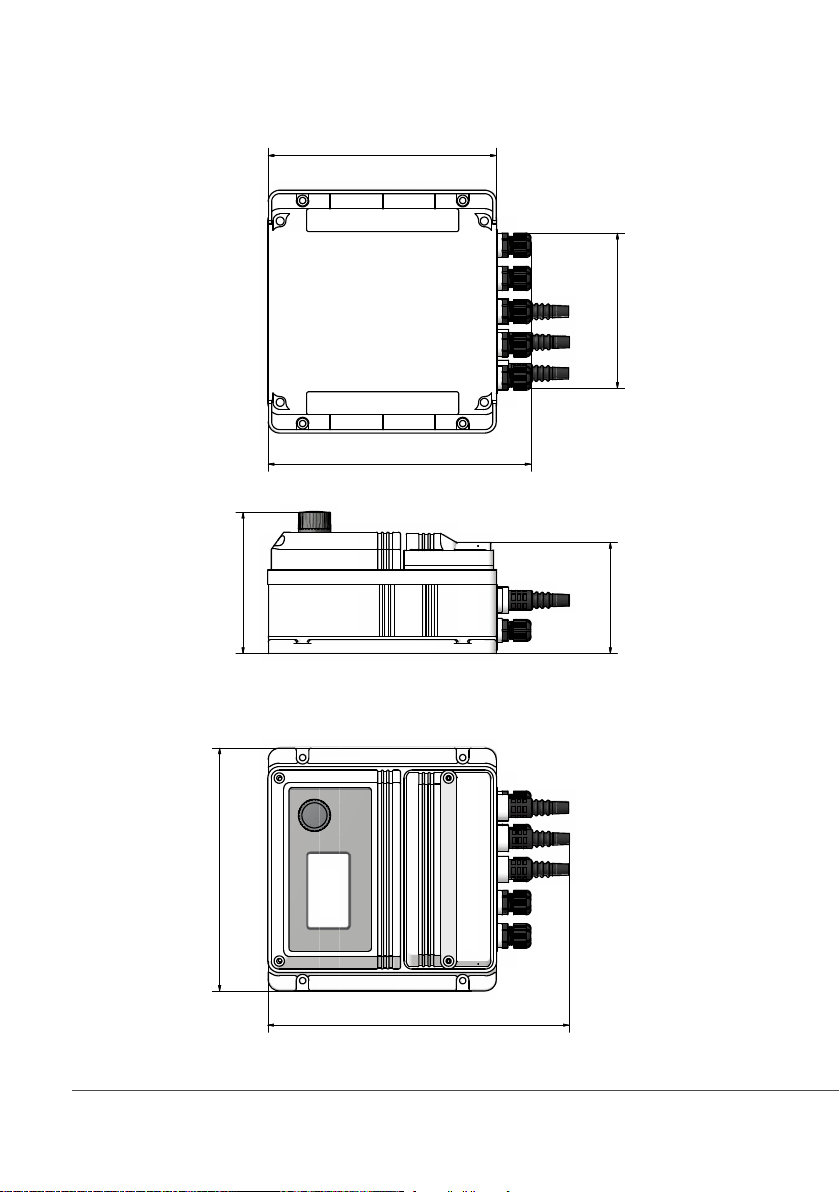
Appendix E - Dimensions
2
0
0
,
0
0
136,00
mm
2
3
0
,
0
0
213,00
124,00
2
6
4
,
0
0
97,00
41
Page 42
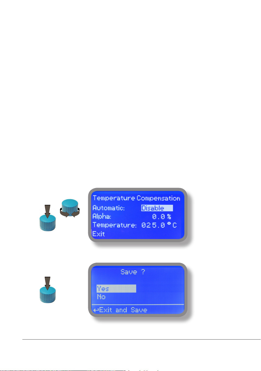
Appendix F - “Temperature compensation”
Conductivity measurements are temperature dependent. The degree to which temperature affects conductivity varies
from solution to solution and can be calculated using the following formula:
Gt = Gtcal {1 + a(T-Tcal)}
where: Gt = conductivity at any temperature T in °C, Gtcal = conductivity at calibration temperature Tcal in °C, a =
temperature coefficient of solution at Tcal in °C.
Substance at 25°C Concentration Alpha (a)
HCl 10 wt% 1.56
KCl 10 wt% 1.88
H2SO4 50 wt% 1.93
NaCl 10 wt% 2.14
Common alphas (a) are listed in the table above. To determine that (a) of other solutions, simply measure conductivity
at a range of temperatures and graph the change in conductivity versus the change in temperature. Divide the slope
of the graph by Gtcal to get a.
Temperature compensation (Alpha) can be changed within 0.0% and 5.0%. It should be set according to measured
chemical properties. If a temperature probe is installed choose “Enable” for “Automatic”. Otherwise select “Disable”
and enter a temperature value in “Temperature” field.
Note: “Temperarure” field is not visible if “Automatic” has been set on “Enable”.
To end procedure move cursor on “OK” and press wheel to proceed to “Save” request screen. Move wheel on
“YES” to save or “NO” to discard changes.
42
Page 43

Index
1. Introduction ........................................................................................3
2. The wheel ............................................................................................ 3
3. Board connectiones .............................................................................4
4. Main view ...........................................................................................5
5. Status check ........................................................................................6
6. Password ............................................................................................. 7
7. “Main Menu” .....................................................................................8
8 “Set-Point”, CD (On/Off) ...................................................................... 9
8.1 “Set-Point”, CD (on/off) .................................................................... 9
8.2 “Set-Point”, CD (proportional) .......................................................... 10
8.3 “PWM” Proportional, CD .................................................................. 11
8.4 “PWM” (fixed), CD ............................................................................12
8.5 “PID”, CD ..........................................................................................13
9 “Probe Calibration”, C .........................................................................14
10. “Parameters” .................................................................................... 16
11. “Output Manager” ............................................................................ 17
12. “Instrument Reset” ........................................................................... 18
13. “Dosing Alarm” .................................................................................19
14. “International”..................................................................................20
15. “Probe Failure” .................................................................................21
16. “Flow Contact” ................................................................................. 22
17. “Service” ..........................................................................................22
18. “mA Outputs” ................................................................................... 23
19. “Out of range alarm” ........................................................................ 24
20. “Self Clean” ......................................................................................25
21. “Circulator pump” ...........................................................................26
22. Technical Information ........................................................................ 27
23. SEPR configuration ............................................................................28
24. “Water Meter” ..................................................................................29
25. “Feed Forward” and mA module ....................................................... 30
LDSCD PLUS D Timered Version ...............................................................31
Appendix - probe modules ...................................................................... 32
Appendix - Electrovalve Connection .......................................................33
Appendix - “Module SMS/GSM” ............................................................34
Appendix - “Module USB for data log”..................................................35
Appendix - Communication ...................................................................36
Appendix - MODBUS ............................................................................... 40
Appendix - Dimensions ........................................................................... 41
Appendix - Compensation .......................................................................42
Information on this manual may contain technical inaccuracies or typographical errors.
The information contained may be changed at any time without prior notication or obligation.
43
Page 44
When dismantling this instrum ent please separate material types and send them according to local recycling disposal requirements.
We appreciate your efforts in supporting your local Recycle Environmental Program.
Working together we’ll form an active union to assure the world’s invaluable resources are conserved.
44
 Loading...