

Page 1
NORMALAB France
2012
N O R M A L A B F r a n c e
1/118
NORMALAB France
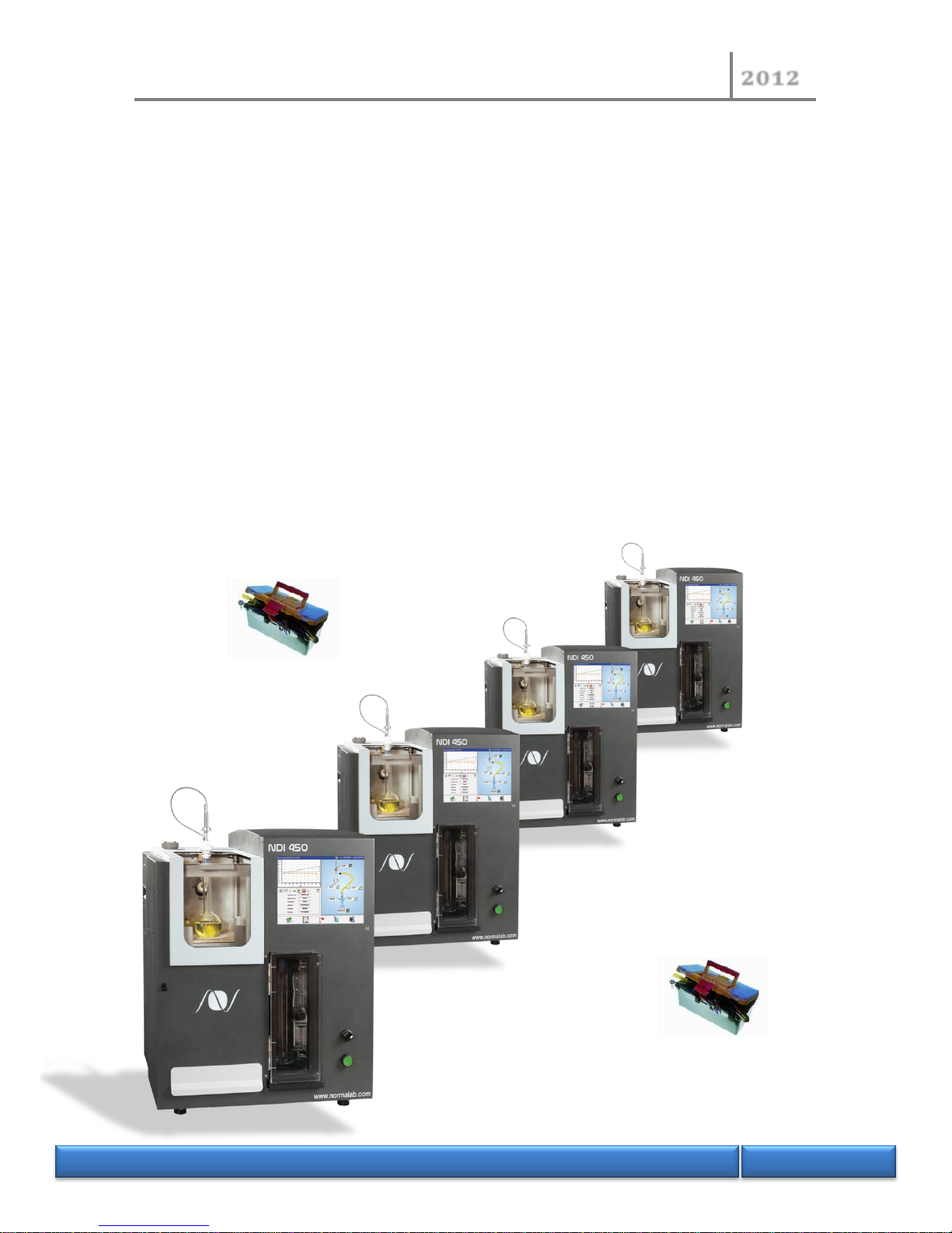
MAINTENANCE NOTICE
NDI 450
Page 2
NORMALAB France
2012
N O R M A L A B F r a n c e
2/118
1 CONTENTS
1 CONTENTS 2
2 STRUCTURE OF THE MACHINE 6
2.1 MECHANICAL STRUCTURE 6
2.1.1 HEATING BLOCK 6
2.1.2 SUBSET COMPARTMENT 6
2.1.3 SUBSET CONDENSER 7
2.1.4 THE VENTILATION 7
2.2 ENVIRONNEMENT OF THE MACHINE 8
2.3 ELECTRONIC STRUCTURE 9
2.3.1 ELECTRONIC STRUCTURE 9
2.3.2 LOCATION OF THE ELECTRONIC BOARDS 9
2.3.3 THE EXTERNAL CONNECTIONS 11
3 INSTRUCTION SHEETS 12
3.1 ACCESS TO PARTS OF THE MACHINE 12
3.1.1 OPENING THE PANELS 12
3.1.2 REMOVING THE FRONT PANEL 13
3.1.3 ACCESS TO THE ELECTRONIC DRAWER 15
3.2 LEVEL FOLLOWER 16
3.2.1 REPLACEMENT OF THE 1RST DROP OPTICAL SENSOR 16
3.2.2 REPLACEMENT OF THE FOLLOWER OPTICAL SENSOR 17
3.2.3 REPLACEMENT OF THE LIMIT SWITCHES OF FOLLOWER 18
3.2.4 REPLACEMENT OF DRIP DEFLECTOR DETECTOR 19
3.2.5 REPLACEMENT OF STEP BY STEP MOTOR 22
3.2.6 REPLACEMENT OF THE MOTOR BOARD 24
3.2.7 REPLACEMENT OF DETECTOR OR MAGNET OF COMPARTMENT DOOR 25
3.3 HEATING BLOCK 26
3.3.1 REPLACEMENT OF THE HEATING ELEMENT 26
3.3.2 REPLACEMENT OF TURBINE 27
3.3.3 REPLACEMENT OF FIRE DETECTION THERMOCOUPLE 28
3.3.4 REPLACEMENT OF VAPOR PROBE’S DETECTOR 29
3.3.5 REPLACEMENT THE MECHANICAL SYSTEM OF SAMPLE PROBE DETECTION 30
3.3.6 REPLACEMENT OF HEATING BLOCK DOOR’S DETECTOR 30
Page 3

NORMALAB France
2012
N O R M A L A B F r a n c e
3/118
3.4 CONDENSER 31
3.4.1 REPLACEMENT CONDENSER PROBE 31
3.5 COOLING CONDENSER SYSTEM 32
3.5.1 REPLACEMENT OR DRAIN OF THE COOLANT LIQUID CIRCUIT 32
3.5.2 REPLACEMENT OF PUMP 32
3.5.3 REPLACEMENT OF FILTER OR FAN 35
3.5.4 REPLACEMENT OF FAN 36
3.5.5 REPLACEMENT OF FAN SPEED THERMOSTAT 36
3.5.6 REPLACEMENT OF PELTIER SUBSET 37
3.5.7 ADJUSTMENT OR REPLACEMENT OF THE LIQUID LEVEL DETECTOR 40
3.5.8 REPLACEMENT OF SUBSET PELTIER POWER SUPPLY 41
3.6 COMPARTMENT COOLING SYSTEM 42
3.6.1 REPLACEMENT OF THE FILTERS OR FANS 42
3.6.2 REPLACEMENT OF THE PELTIER SUBSET OF RECEIVER COMPARTMENT 43
3.6.3 REPLACEMENT OF THE COMPARTMENT PROBE 46
3.6.4 REPLACEMENT OF SUBSET PELTIER POWER SUPPLY 47
3.7 CHASSIS 47
3.7.1 REPLACEMENT OF THE HEATING TRANSFORMER 47
3.7.2 REPLACEMENT OF THE HEATING FUSE 48
3.7.3 REPLACEMENT OF THE CIRCUIT BREAKER 49
3.7.4 REPLACEMENT OF THE CL3 BOARD 50
3.7.5 REPLACEMENT OF THE AMBIENT PROBE 51
3.8 ELECTRONIC DRAWER 51
3.8.1 REPLACEMENT OF THE CL1 BOARD 51
3.8.2 THE BAROMETRIC SENSOR 52
3.8.3 REPLACEMENT PROCESS OF THE MICROPROCESSOR BOARD 53
3.8.4 REPLACEMENT OF THE POWER SUPPLY OF UC BOARD OR STEP BY STEP MOTOR 53
3.9 FRONT PANEL 54
3.9.1 REPLACEMENT OF MMI MICROPROCESSOR BOARD 54
3.9.2 REPLACEMENT OF THE HARD DRIVE DISK 54
3.9.3 REPLACEMENT OF THE LCD DISPLAY 55
3.9.4 REPLACEMENT OF INVERTER BACKLIGHT 56
3.9.5 REPLACE THE TOUCH SCREEN CONTROLLER 56
4 CALIBRATION AND MAINTENANCE FUNCTIONS 57
4.1 CALIBRATION FUNCTIONS 57
4.2 OPTIONS AND EQUIPMENT REQUIRED 59
4.3 CALIBRATION OF SAMPLE TEMPERATURES 59
4.3.1 EXAMPLE OF CREATION OF A NEW CALIBRATION 60
4.3.2 COMMISSIONING A NEW SAMPLE TEMPERATURE PROBE 64
4.4 THE PT 100 TEMPERATURE PROBES INTERNAL TO THE INSTRUMENT 64
4.5 TEMPERATURE MEASUREMENTS BY THERMOCOUPLE 65
4.6 CALIBRATION OF THE BAROMETRIC SENSOR 65
Page 4
NORMALAB France
2012
N O R M A L A B F r a n c e
4/118
4.7 CALIBRATION OF TEST TUBES 67
4.8 CALIBRATION OF THE TACTILE PAD 68
4.9 MONITORING EXPIRY OF CALIBRATION DEADLINES 68
5 DENOMINATION AND FUNCTIONS OF THE ELECTRONIC BOARDS 69
5.1 PROCESS CPU 69
5.2 MMI CPU 69
5.3 CL1 BOARD : 69
5.4 CL2 BOARD : 70
5.5 CL3 BOARD : 70
5.6 CL4 BOARD : 70
5.7 CL56F ET CL 56C BOARDS : 70
5.8 STEPPER BOARD: 71
6 SCHEMATIC ELECTRICAL AND ELECTRONIC 71
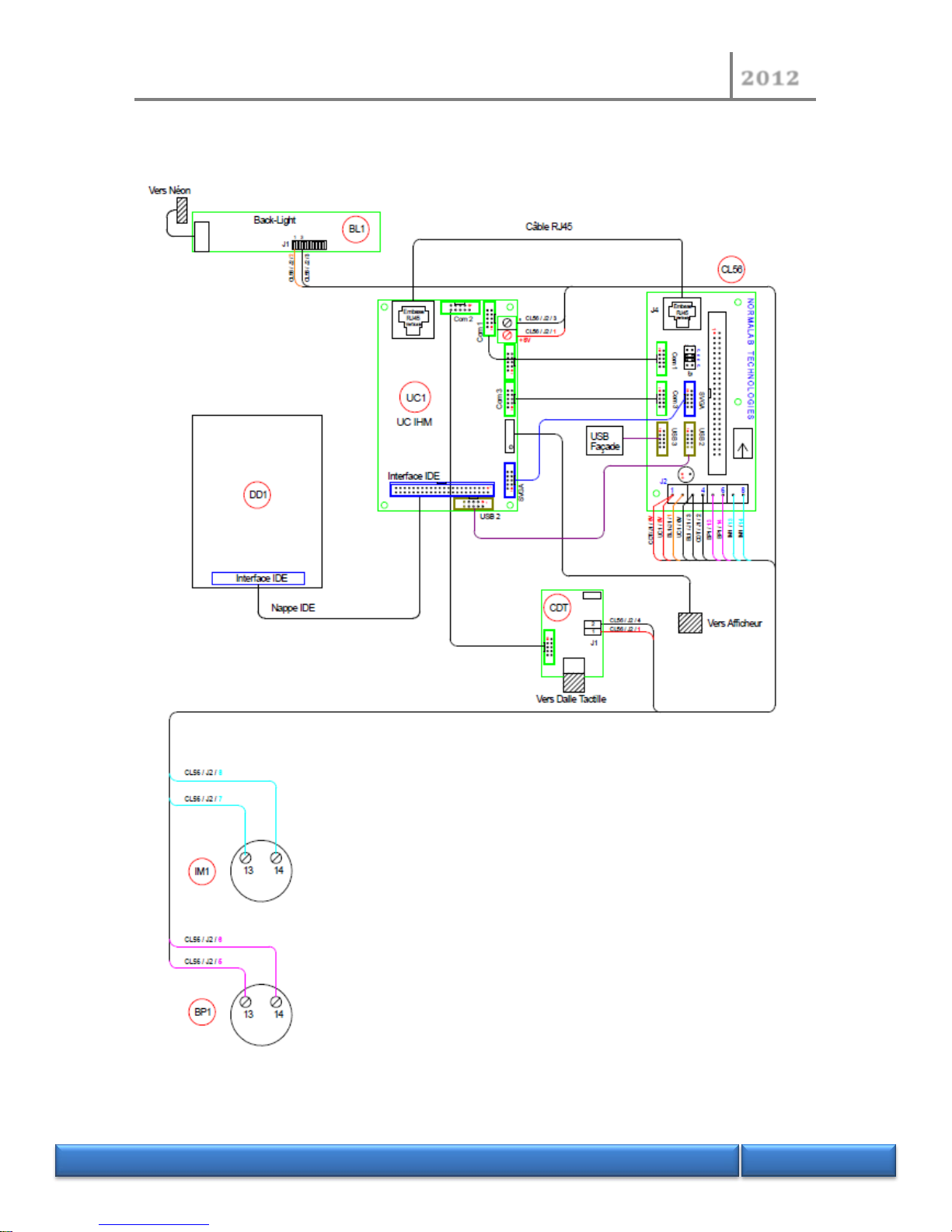
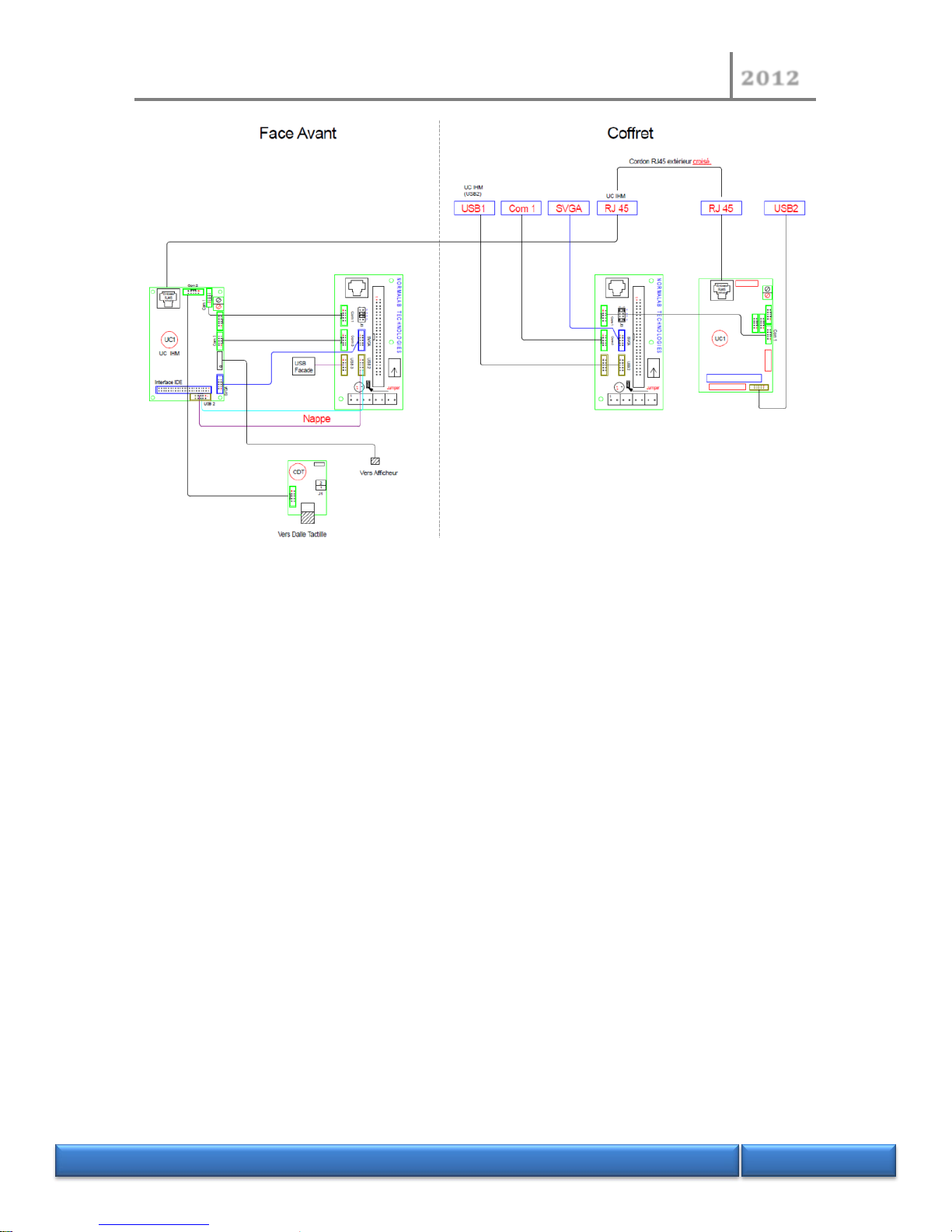
6.1 INTERCONNECTION SCHEME 71
6.2 SPARES PART LIST 73
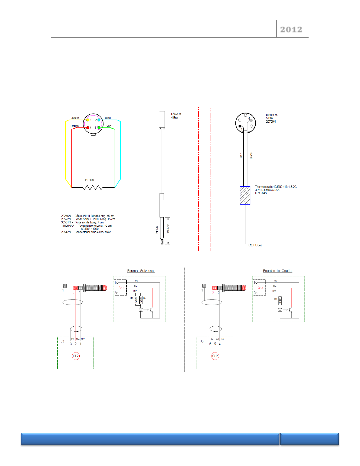
6.2.1 PROBES AND THERMOCOUPLES 73
6.2.2 FIRST DROP AND FOLLOWER OPTICAL SENSORS 73
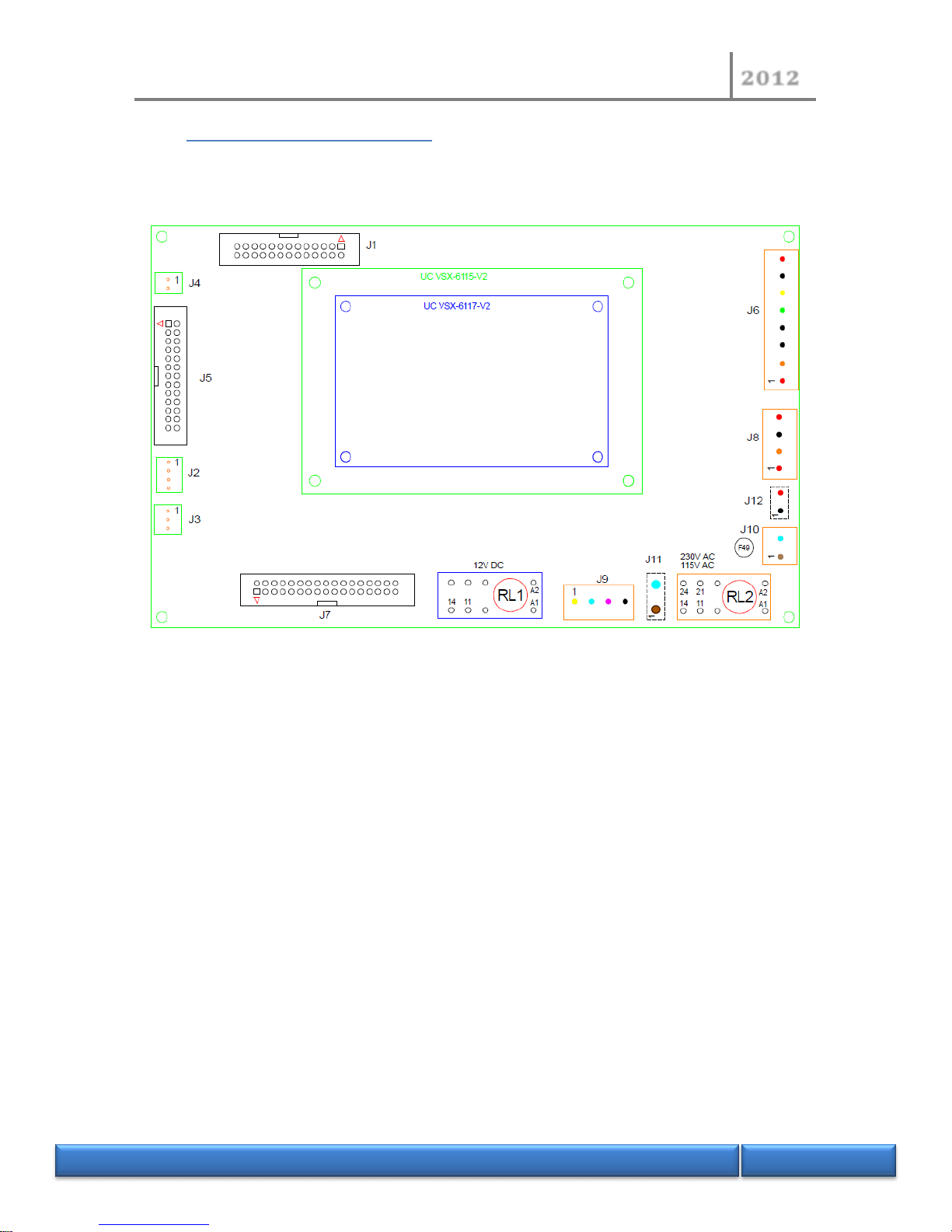
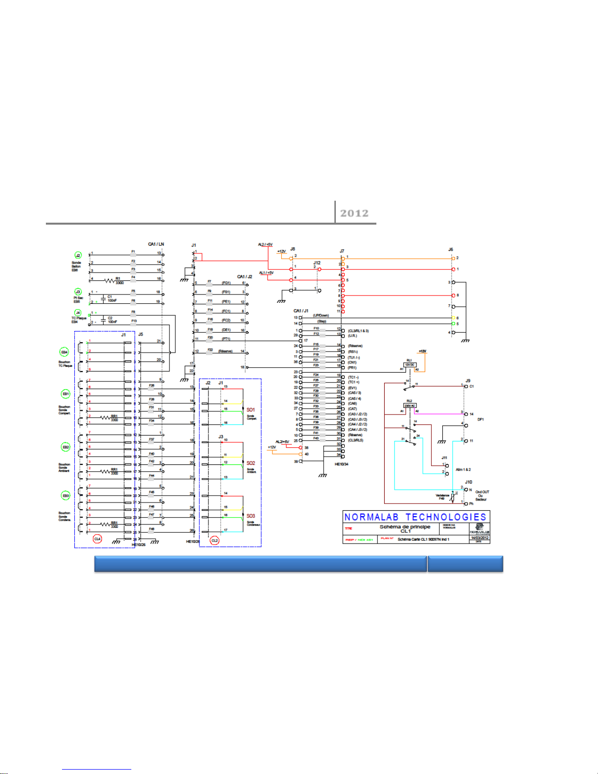
6.3 SCHEME OF ELECTRONIC BOARDS 74
6.3.1 CL1 BOARD 74
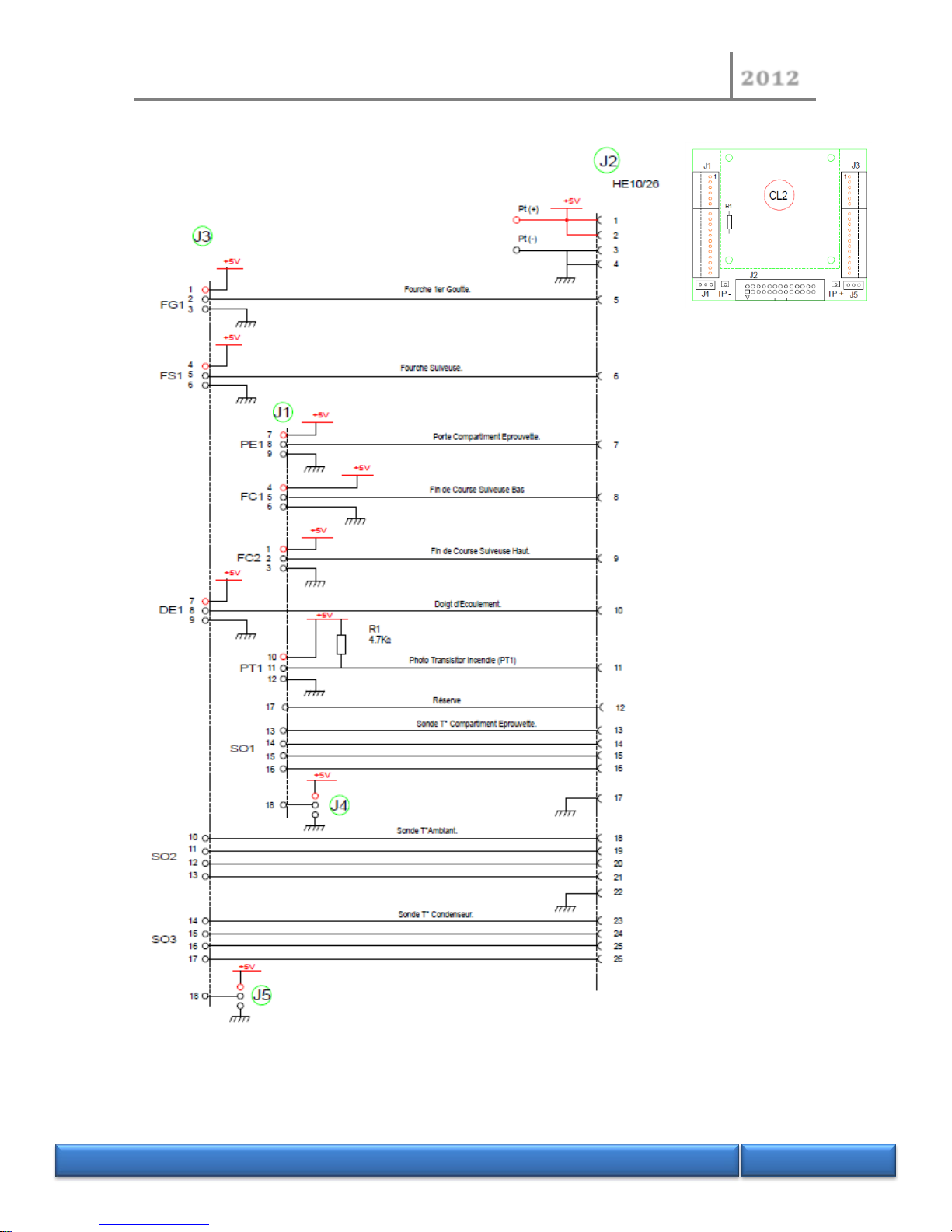
6.3.2 CL2 BOARD 76
6.3.3 CL3 BOARD 77
6.3.4 CL4 BOARD 78
6.3.5 CL56 BOARD 79
6.3.6 STEPPER MOTOR BOARD 80
6.3.7 DETECTOR PROBE AND DOOR CLOSED DETECTOR SENSOR 80
6.3.8 FRONT PANEL 81
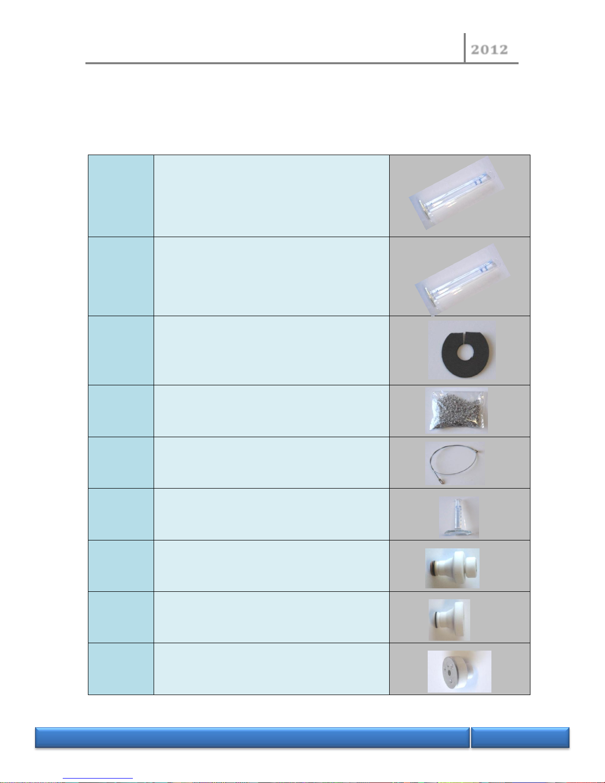
7 SPARES PART LIST 83
8 TROUBLES SHOOTING 93
9 ANNEXE 1 97
9.1 GUIDE TO UPDATE INSTRUMENT 97
9.2 SAFETY RULES 97
9.3 GENERAL CHARACTERISTICS 97
9.4 CONTENT OF NEW VERSION 97
9.5 HOW TO GET A NEW VERSION 97
9.6 HOW TO KNOW THE SOFTWARE VERSION 98
Page 5
NORMALAB France
2012
N O R M A L A B F r a n c e
5/118
9.7 IMPORTANT RECOMMENDATIONS 98
9.8 ADDITIONAL REQUIREMENTS TO UPDATE YOUR NDI450 INSTRUMENT 98
9.9 PREPARE YOUR USB FLASH DRIVE FOR UPDATING (VIDEO EXAMPLE) 98
9.10 INSTALL A NEW MMI VERSION USING THE UPDATE OPTION (VIDEO EXAMPLE) 100
9.11 INSTALL A NEW FIRMWARE VERSION USING THE UPDATE OPTION (VIDEO EXAMPLE) 103
9.12 ERROR MESSAGES 106
10 ANNEXE 2 107
10.1 LOGBOOK 107
11 ALARM LIST 111
12 NOTES : 117
Version 04-2012
Page 6
NORMALAB France
2012
N O R M A L A B F r a n c e
6/118
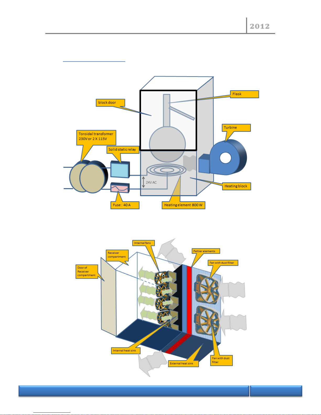
2 Structure of the machine
2.1 Mechanical structure
2.1.1 Heating block
2.1.2 Subset compartment
Page 7
NORMALAB France
2012
N O R M A L A B F r a n c e
7/118
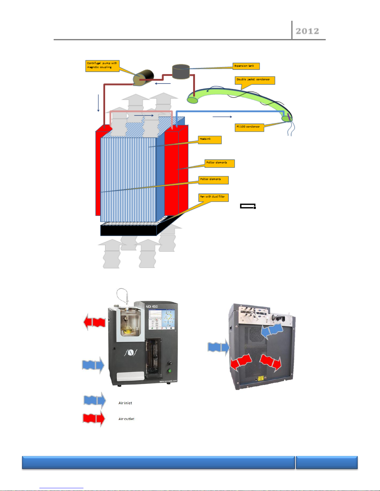
2.1.3 Subset condenser
2.1.4 The ventilation
Page 8

NORMALAB France
2012
N O R M A L A B F r a n c e
8/118
2.2 Environnement of the machine
The machine must be installed on the stable bench , can supported the weight of the apparatus ( see
characteristics)
It is necessary to respect a minimum environment volume to ensure proper operation and longevity
.
Allow minimum space : 25cm behind and 40 cm on the sides , 100 cm above to ensure adequate
ventilation space.
Do not install the machine near the heating source ( radiator , stove , oven or apparatusl sending hot
air , …), or behing a window receiving the sun
Page 9
NORMALAB France
2012
N O R M A L A B F r a n c e
9/118
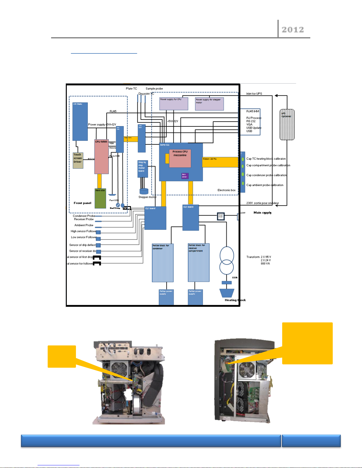
2.3 Electronic structure
2.3.1 Electronic structure
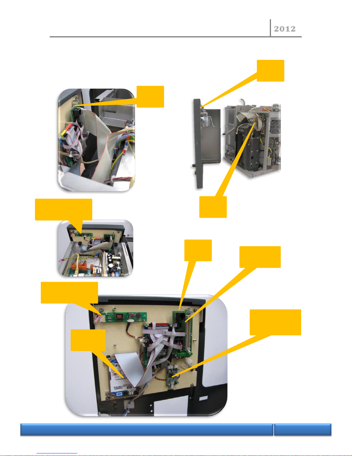
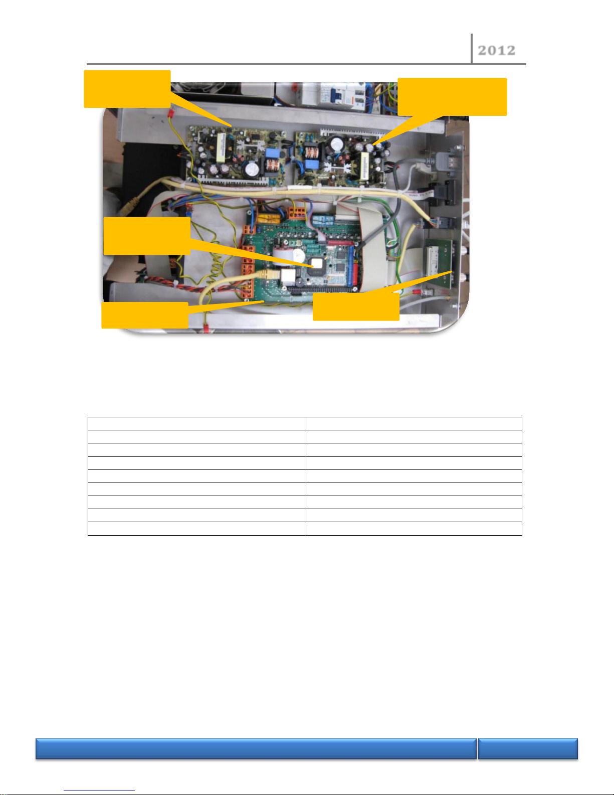
2.3.2 Location of the electronic boards
CL3
board
CL2 board and
Stepper motor
board
Page 10
NORMALAB France
2012
N O R M A L A B F r a n c e
10/118
CL56F
board
CL56C
board
Inverter pour
backlight
CL56F
board
MMI CPU
board
Touch screen’s
driver
Hard
drive disk
Inverter pour
backlight
CL56F
board
Page 11
NORMALAB France
2012
N O R M A L A B F r a n c e
11/118
2.3.3 The external connections
2.3.3.1 Keyboard, mouse, printer, monitor, network
Devices type
Port
Video monitor
VGA port on the back side
Keyboard
USB Port on the left side and back side
Printer
USB Port on the left side and back side
Network
Port RJ 45 on the back side
Serial port
Com port on the back side ( 9 pins SubD)
USB key for exportation files
USB Port on the left side and back side
USB key for process restoration
Update port USB
USB Key for MMI or standard update
USB Port on the left side and back side
Power supply
for CPU
Power supply for
stepper motor
CL4 Board
CL1 Board
CPU Process
Page 12
NORMALAB France
2012
N O R M A L A B F r a n c e
12/118
3 Instruction sheets
3.1 Access to parts of the machine
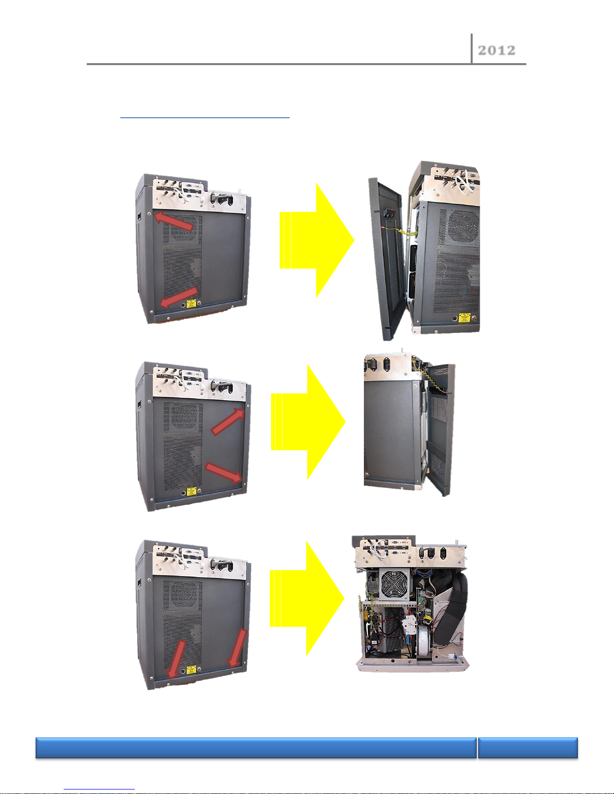
3.1.1 Opening the panels
Page 13
NORMALAB France
2012
N O R M A L A B F r a n c e
13/118
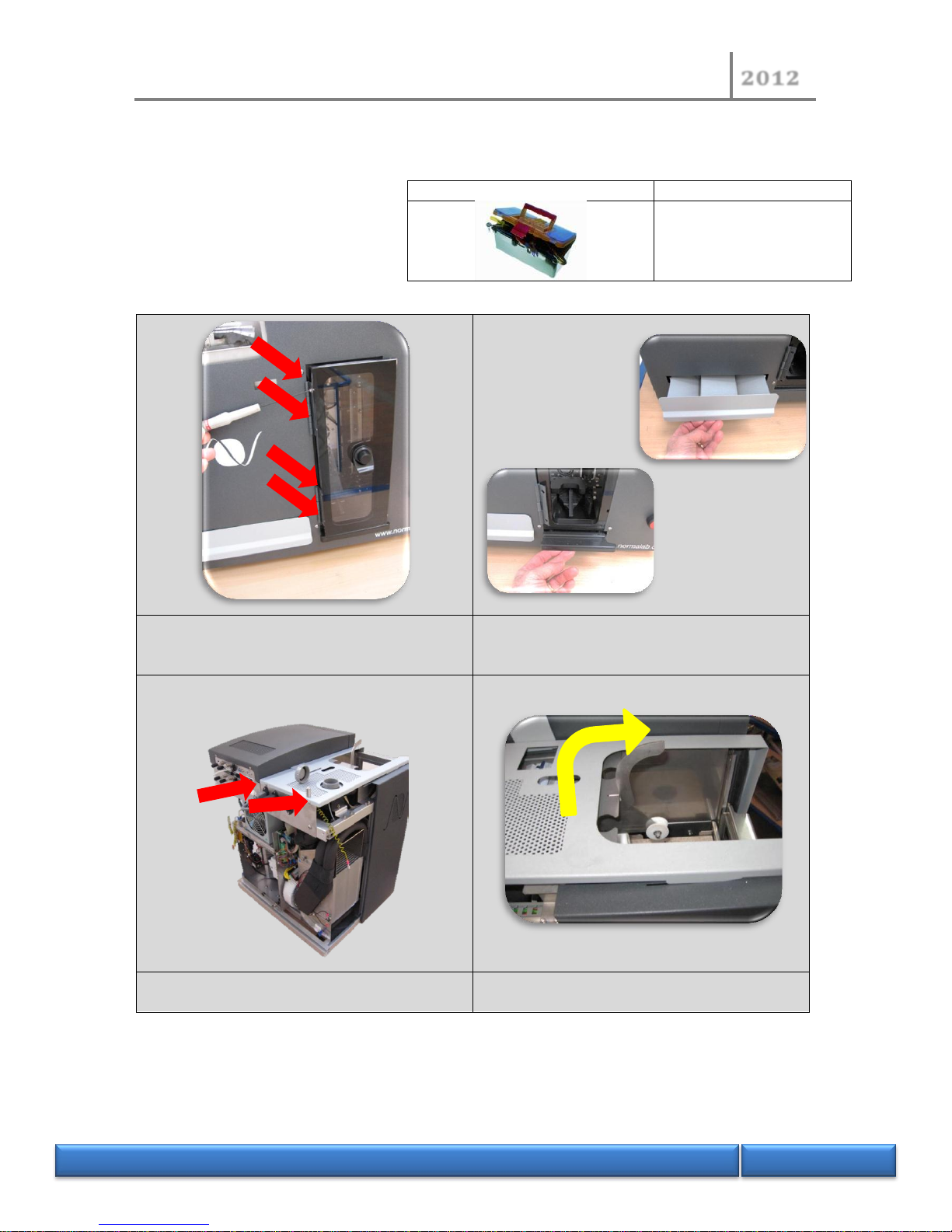
3.1.2 Removing the front panel
Remove the side and rear panels (see
above procedure 3.1.1)
Remove the compartment door : remove the 4
hinge screws
Remove the 2 drawers :
- Condensates drawer of compartment
- Drawer under heating block
Remove the cap of the expansion tank
Remove the 2 screws
Remove the upper panel
Tools
1 hex head key 2 mm
1 hex head key 2.5 mm
1 hex head key 3 mm
Page 14
NORMALAB France
2012
N O R M A L A B F r a n c e
14/118
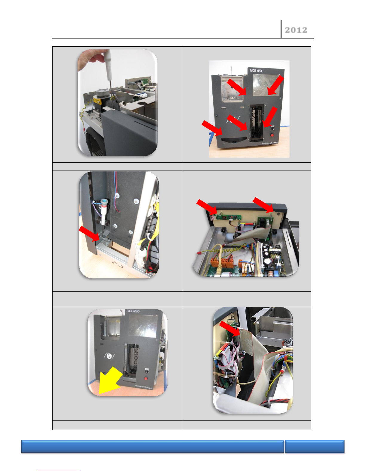
Remove the holding screw on the left side
Remove the 5 screw of the front panel
Remove this holding screw
Remove the 2 black knobs fixing the electronic
drawer
Pull slightly the panel forward
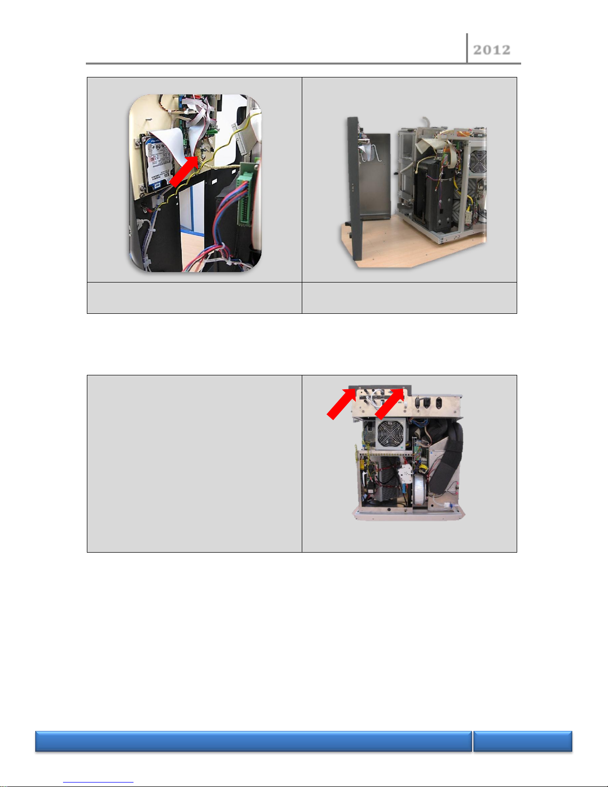
Unplug the ribbon of front panel
Page 15
NORMALAB France
2012
N O R M A L A B F r a n c e
15/118
Unplug the network cable ( RJ45)
The front panel is free , you can remove it
3.1.3 Access to the electronic drawer
Remove the 2 screws of the upper left panel and
lift the panel on the back
Remove the ground wire
Page 16
NORMALAB France
2012
N O R M A L A B F r a n c e
16/118
3.2 Level follower
3.2.1 Replacement of the 1rst drop optical sensor
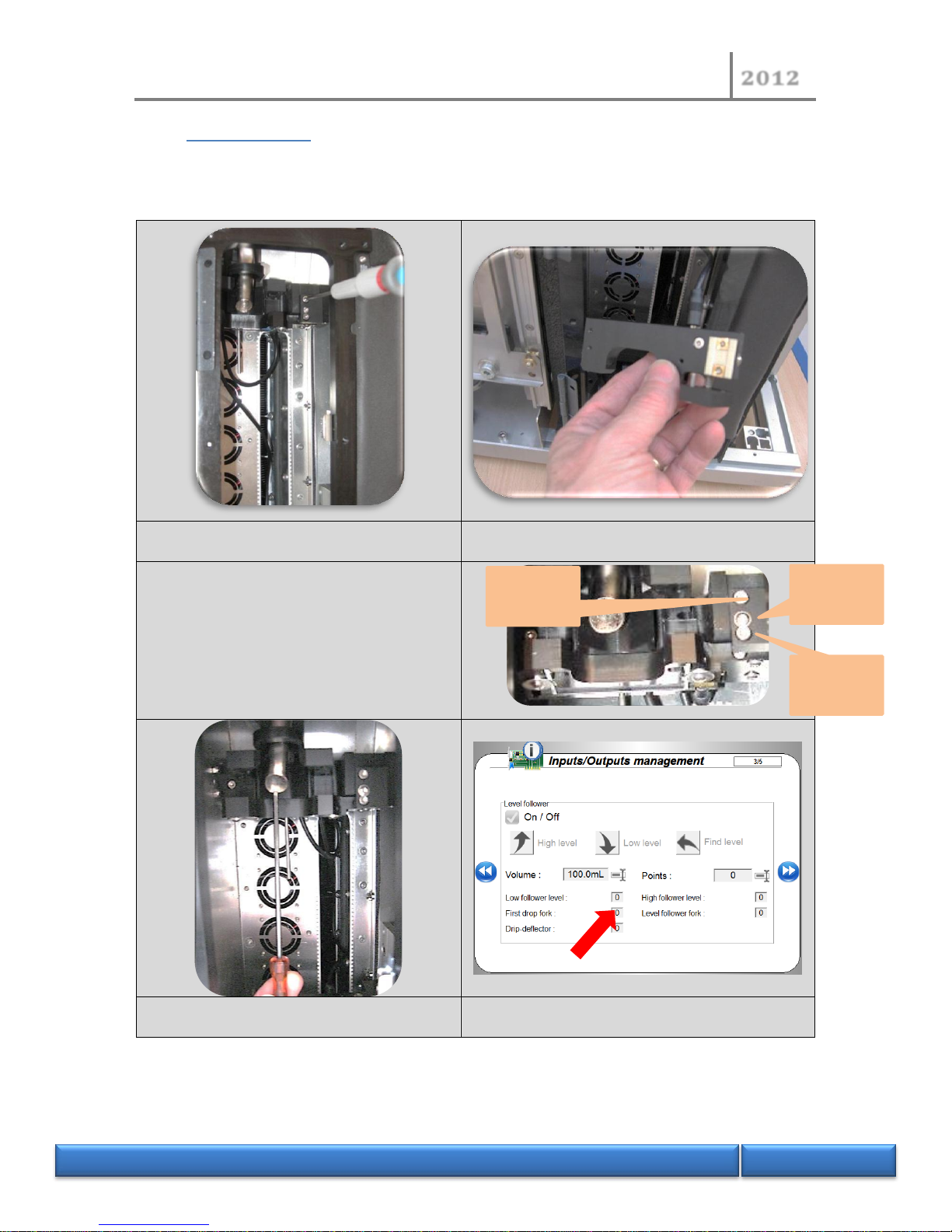
Remove the holding screw
Pull out the optical sensor from the slide
Remove the Jack connector
Plug the connector on the new optical sensor
(Pay attention at the cable to not hinder the
movement of the follower)
Replace the new optical sensor in the slide
Tighten the holding screw
Loosen the locking screw to adjust the optical
position with the adjusting screw
Place a 4mm Ø screwdriver in vertical position
and aligned with the condenser
Read the good position on the maintenance screen
( adjust slowly because the refreshment is slow)
Locking
screw
Holding
screw
Adjusting
screw
Page 17
NORMALAB France
2012
N O R M A L A B F r a n c e
17/118
3.2.2 Replacement of the follower optical sensor
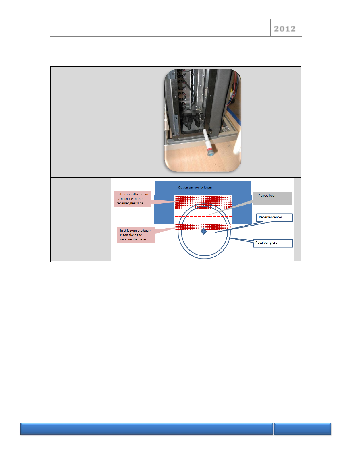
With the
maintenance
functions ,to do
raise the follower
sensor of 5 cm to
release it from the
follower base
Proceed the same
way as first drop
sensor to remove
the optical sensor
Loosen the
blocking screw and
adjust the optical
sensor position
with the adjusting
screw
Page 18
NORMALAB France
2012
N O R M A L A B F r a n c e
18/118
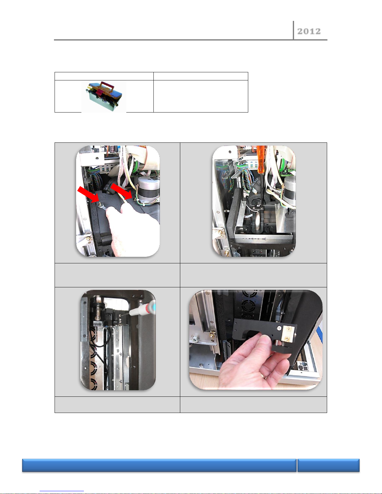
3.2.3 Replacement of the limit switches of follower
Tools
1 hex head key 4 mm
1 tubular key 5.5 mm
1 flat blade screwdriver 3.5m
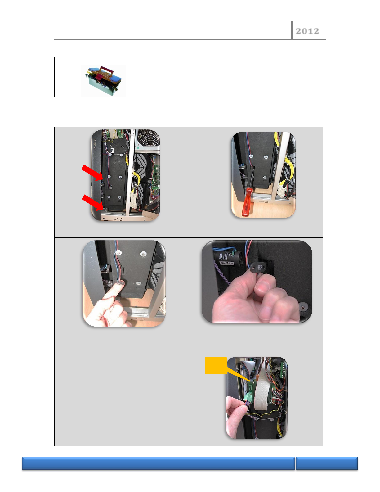
Remove the right panel (see the above procedure 3.1.1)
Position of the low and high sensors
Loosen the maintaining nut of sensor
Release the wires
Extract the sensor ( identify the sense of the
position to replace the new one in the same
sense)
Disconnect the wires from connector of
CL2 board
Low sensor :
- Red 1
- Blue 2
- Black 3
High sensor
- Red 4
- Blue 5
- Black 6
1
Page 19
NORMALAB France
2012
N O R M A L A B F r a n c e
19/118
3.2.4 Replacement of drip deflector detector
Tools
1 hex head key 3 mm
1 wrench 7mm
Remove the front panel (see above procedure 3.1.1)
Remove the roof of the receiver
compartment(2 hex screws)and extract it
(take care at the heating insulation)
Remove the flange around the condenser
Remove the optical sensor ( without
modifying the position adjustment)
Unplug the optical sensor cable
Page 20
NORMALAB France
2012
N O R M A L A B F r a n c e
20/118
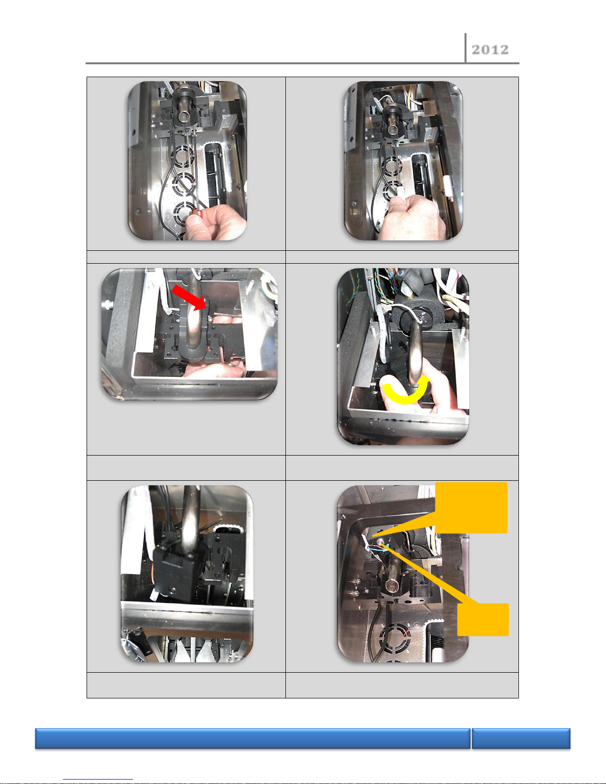
Remove the 2 maintaining scews
Remove the compartment probe
Lift the probe above condenser
Release the wires and turn the holder around the
condenser ( lift slightly the condenser tube)
Place the holder in front of condenser tube
to access by above
Loosen the maintaining screw
Vis de
maintien
capteur
Capteur
Page 21
NORMALAB France
2012
N O R M A L A B F r a n c e
21/118
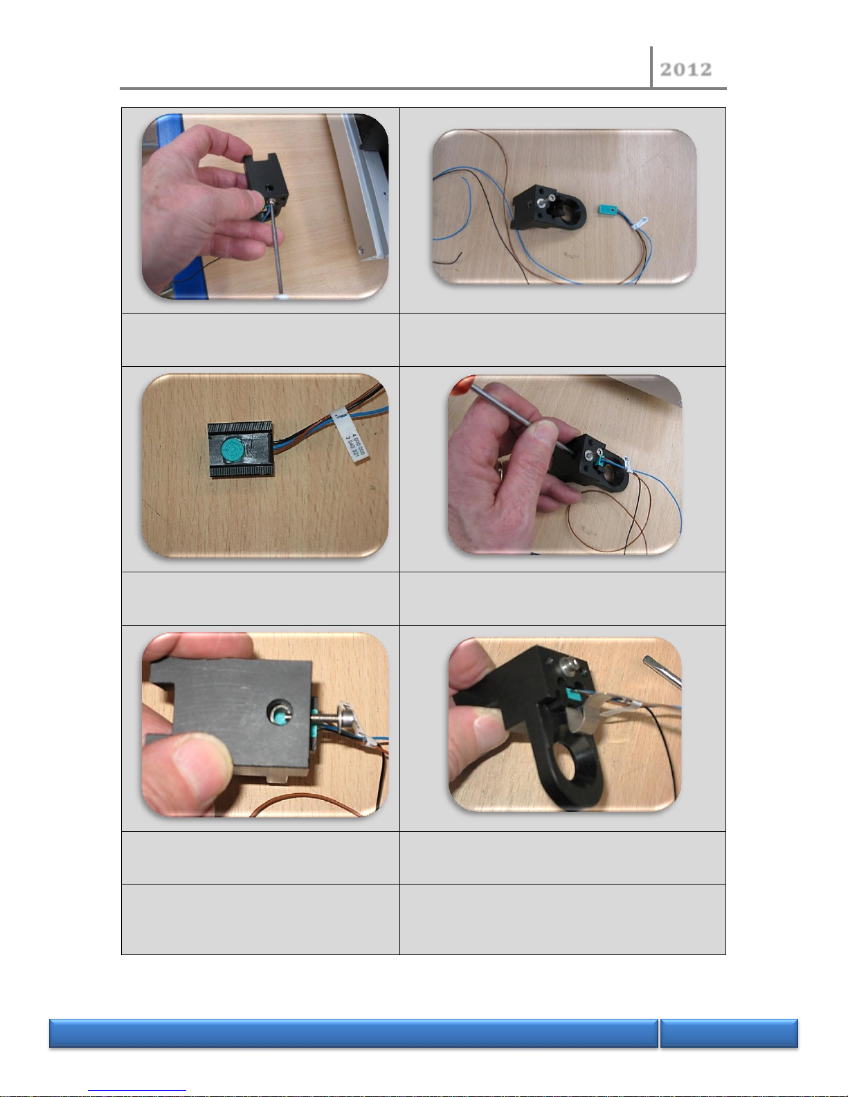
Remove completely the screw and close the
hole to maintain the spring
Once the screws to release the spring, the sensor can
be extracted (mark the direction of the sensor)
Place the new sensor in the holder(the target
must be to the drip deflector)
Replace the medium in the slide, put the spring, push
the spring so that the screw can pass
Tighten the screw taking care the spring is
below
Check the mechanical operation with your drip
deflector
Unplug the old sensor
Connect the wires of the new one :
- Brown 7 of J3
- Black 8 of J3
- Blue 9 of J3
Page 22
NORMALAB France
2012
N O R M A L A B F r a n c e
22/118
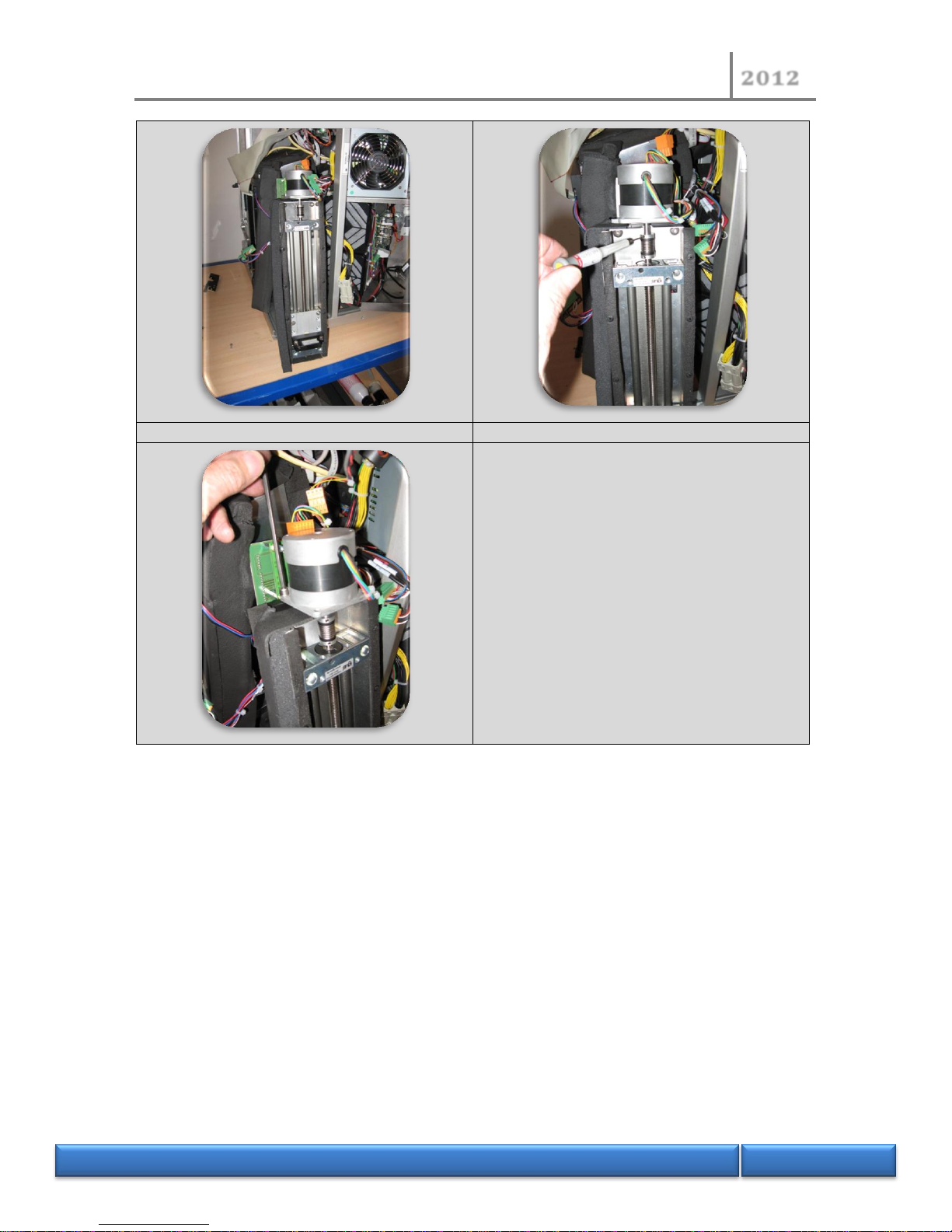
3.2.5 Replacement of step by step motor
Tools
1 hex head key 2.5 mm
1 hex head key 2 mm
1 hex head key 1.5 mm
1 hex head key 4 mm
Remove the follower optical sensor (see above procedure 3.2.2)
Release the wires
Remove the 5 side screws on the left under the
insulation
Remove the 4 side screws on the right under the
insulation
Unplug the pilot wires of motor on the motor
board and the sensors on the CL2 board
Page 23
NORMALAB France
2012
N O R M A L A B F r a n c e
23/118
Return the guide assembly
Loosen the motor coupling
Remove the motor
At the reassembling , replace correctly the
insulation
Page 24
NORMALAB France
2012
N O R M A L A B F r a n c e
24/118
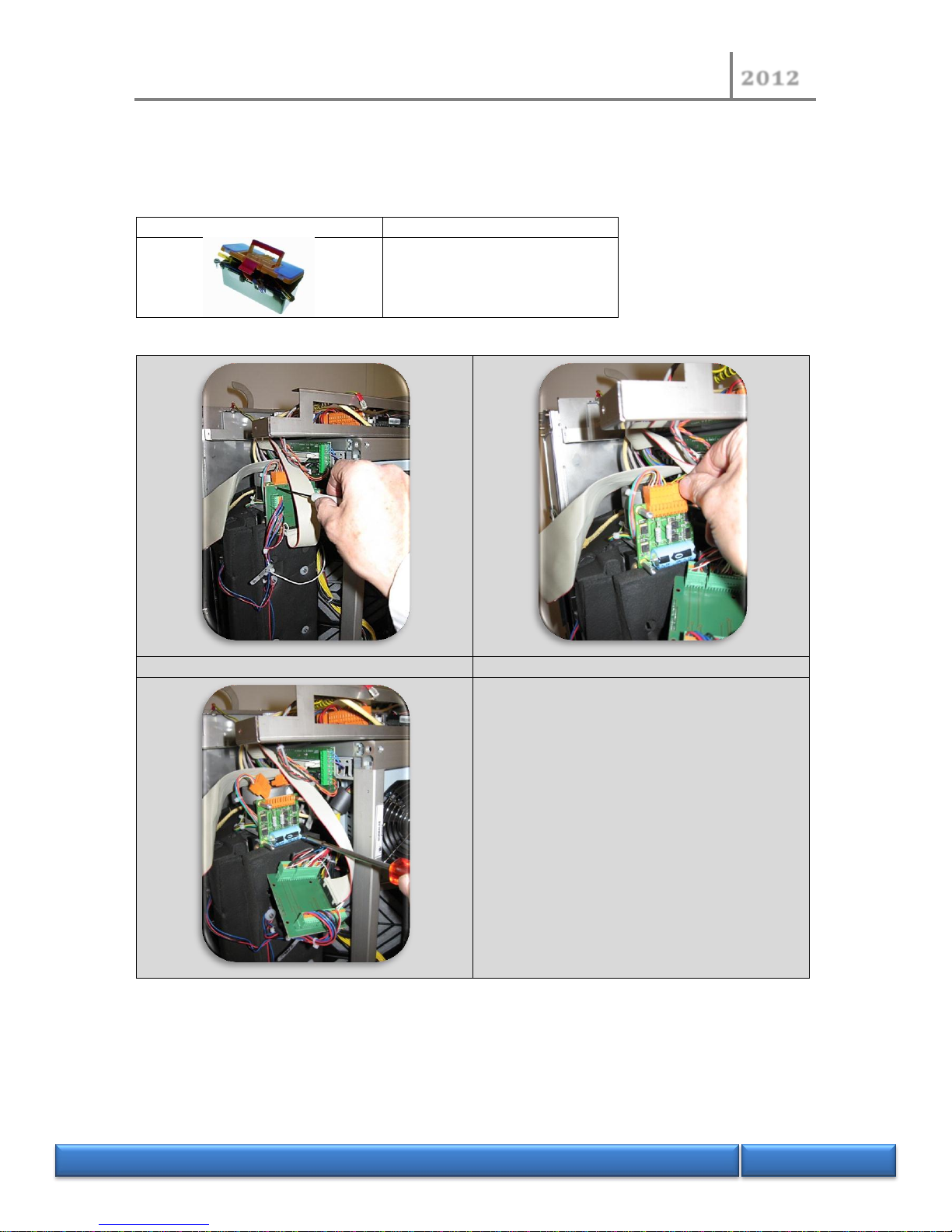
3.2.6 Replacement of the motor board
Tools
1 hex head key 2 mm
1 tube wrench 5.5 mm
Remove the CL2 board with the 4 screws
Remove the connector of the motor board
Remove the motor board
Page 25
NORMALAB France
2012
N O R M A L A B F r a n c e
25/118
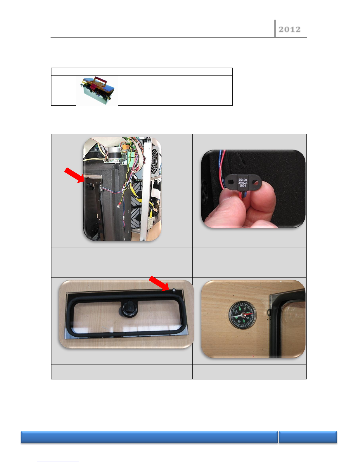
3.2.7 Replacement of detector or magnet of compartment door
Tools
1 hex head key 2 mm
Remove the front panel of the apparatus (see above procedure 3.1.2)
Remove the sensor
- Red wire on 7 of J1
- Blue wire on 8 of J1
- Black wire on 9 of J1
Identify the position of the sensor
The magnet which activates the sensor
The magnet must present a south pole ( it
attracts the North of the compass needle)
Page 26
NORMALAB France
2012
N O R M A L A B F r a n c e
26/118
3.3 Heating block
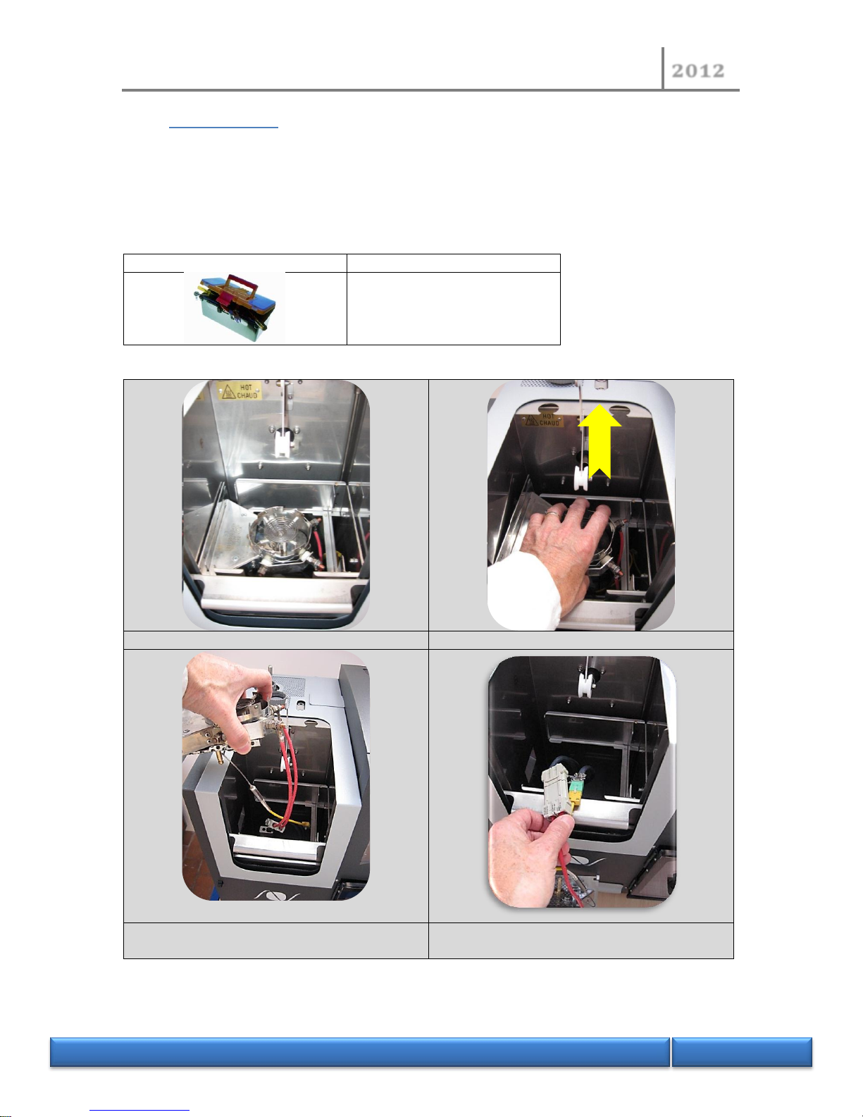
3.3.1 Replacement of the heating element
Tools
1 cutting pliers
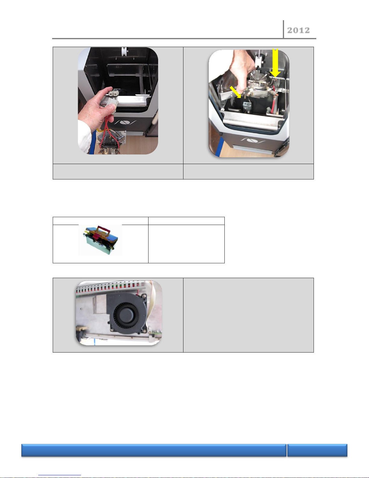
Apparatus power off , and cold heating element
Pull verticaly the heating assembly
Carefully pry the heating element
Access to the connectors of heating element and
thermocouple
Page 27
NORMALAB France
2012
N O R M A L A B F r a n c e
27/118
Plug the new element ( heating and
thermocouple)
Replace by clipping the element
3.3.2 Replacement of turbine
Tools
1 tube wrench 7 mm
1 soldering iron
welding
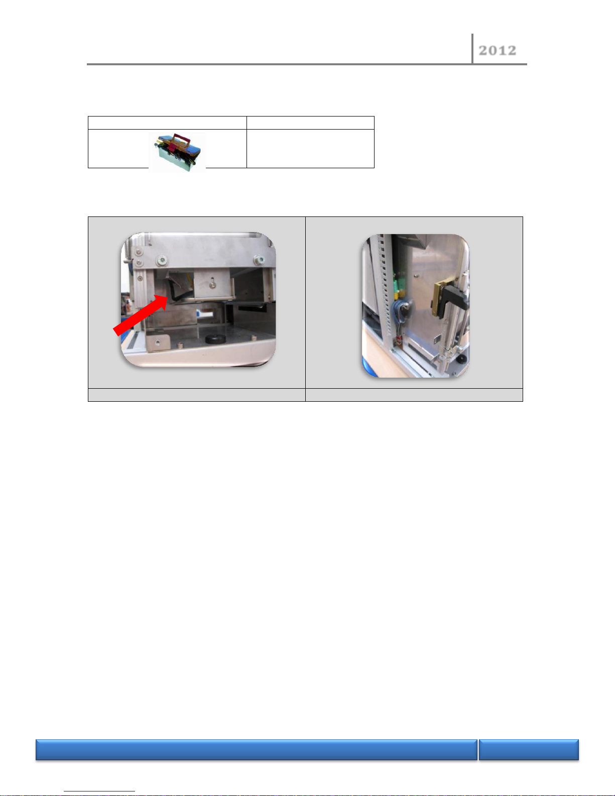
Remove the 3 fixing screws
Follow the wires in the raceway to remake the
splices
Page 28
NORMALAB France
2012
N O R M A L A B F r a n c e
28/118
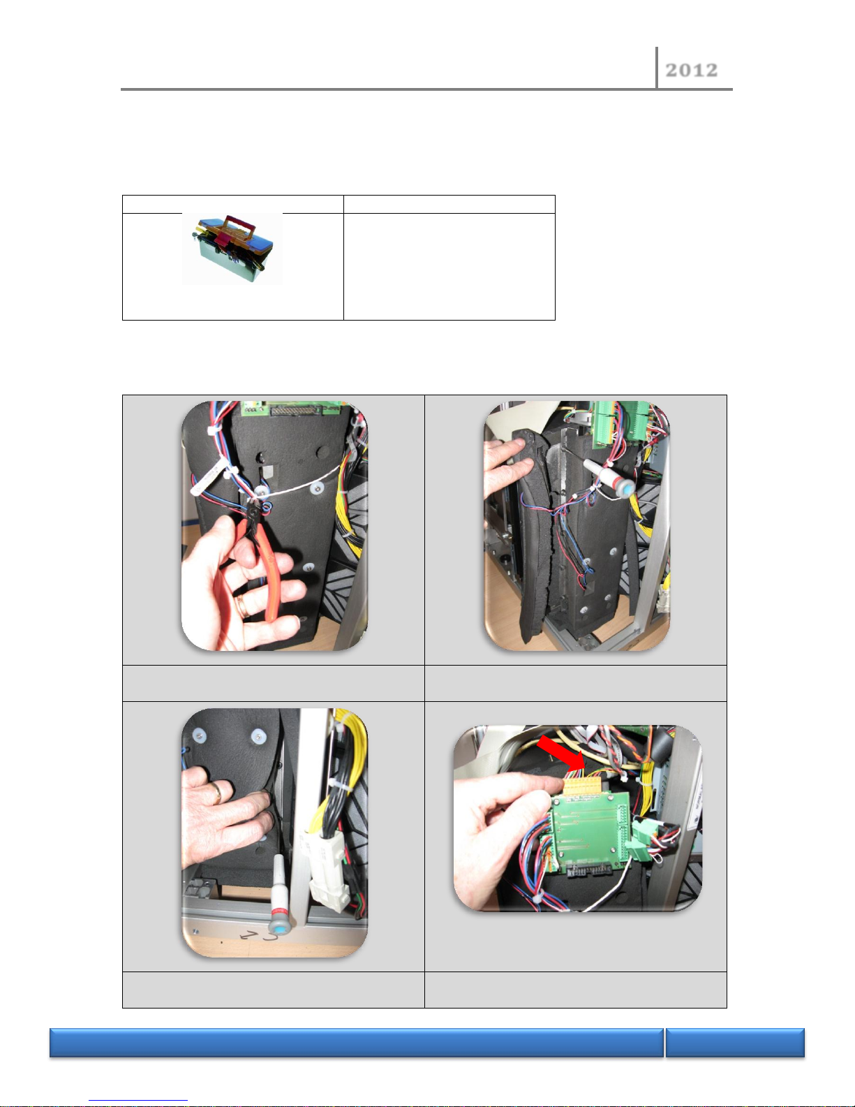
3.3.3 Replacement of fire detection thermocouple
Tools
Cutting pliers
Remove the front panel (see above procedure 3.1.2)
Position of thermocouple
Cut the collar , unplug the thermocouple
Page 29
NORMALAB France
2012
N O R M A L A B F r a n c e
29/118
3.3.4 Replacement of vapor probe’s detector
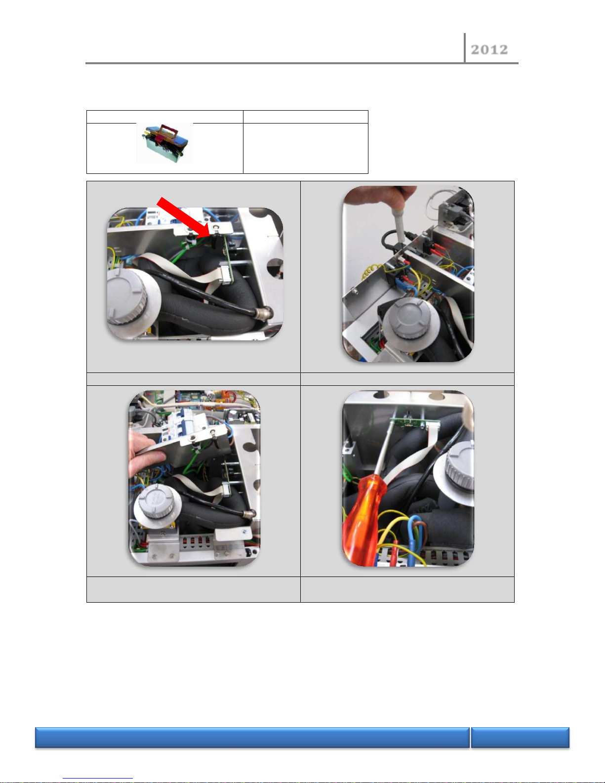
Remove the left upper panel (see above procedure3.1.2)
Position of the sensor
Remove the circuit breaker holder
Remove the circuit breaker holder
Remove the fixing screws of sensor board and
release the ribbon
Tools
1 hex head key 2.5 mm
Page 30
NORMALAB France
2012
N O R M A L A B F r a n c e
30/118
3.3.5 Replacement the mechanical system of sample probe detection
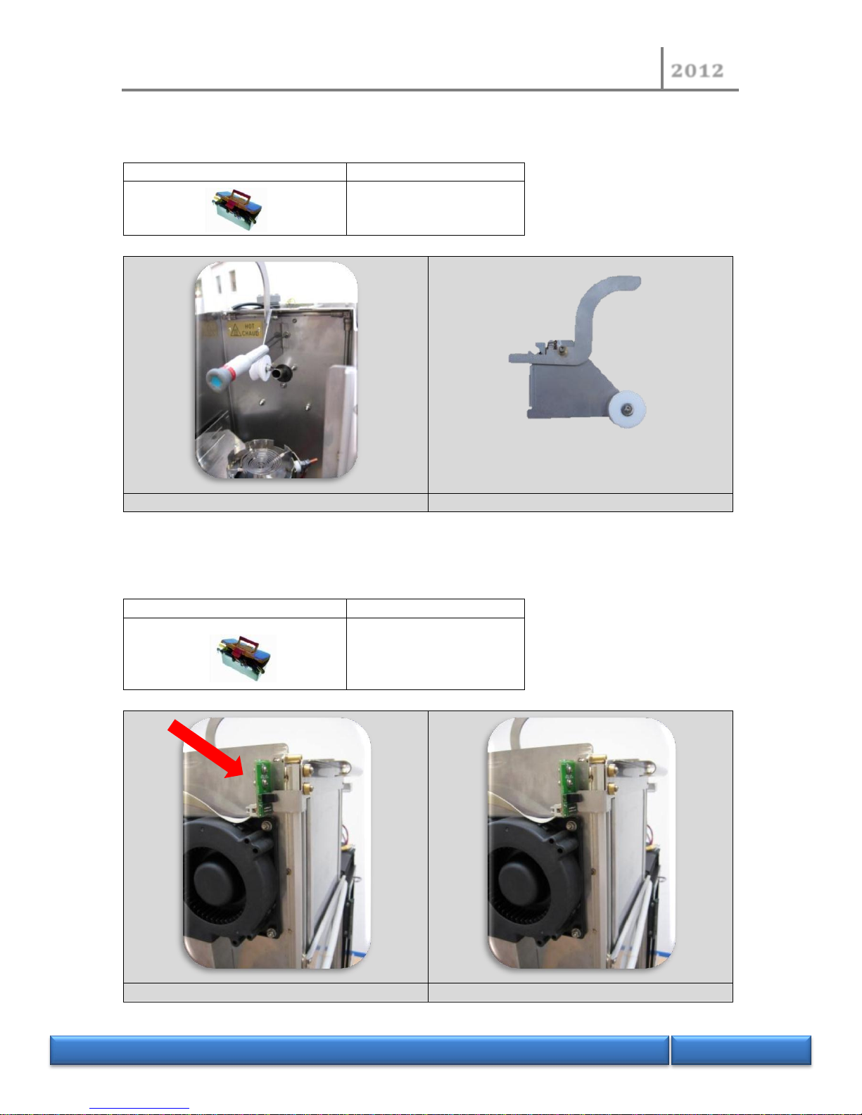
Remove the left upper panel (see above procedure 3.1.1)
Tools
1 hex head key 2.5 mm
Remove the fixing screw
Take care at spring
3.3.6 Replacement of heating block door’s detector
Remove the front panel (see above procedure 3.1.2)
Tools
1 hex head key 2.5 mm
Position of the sensor
Remove the ribbon and the sensor
Page 31
NORMALAB France
2012
N O R M A L A B F r a n c e
31/118
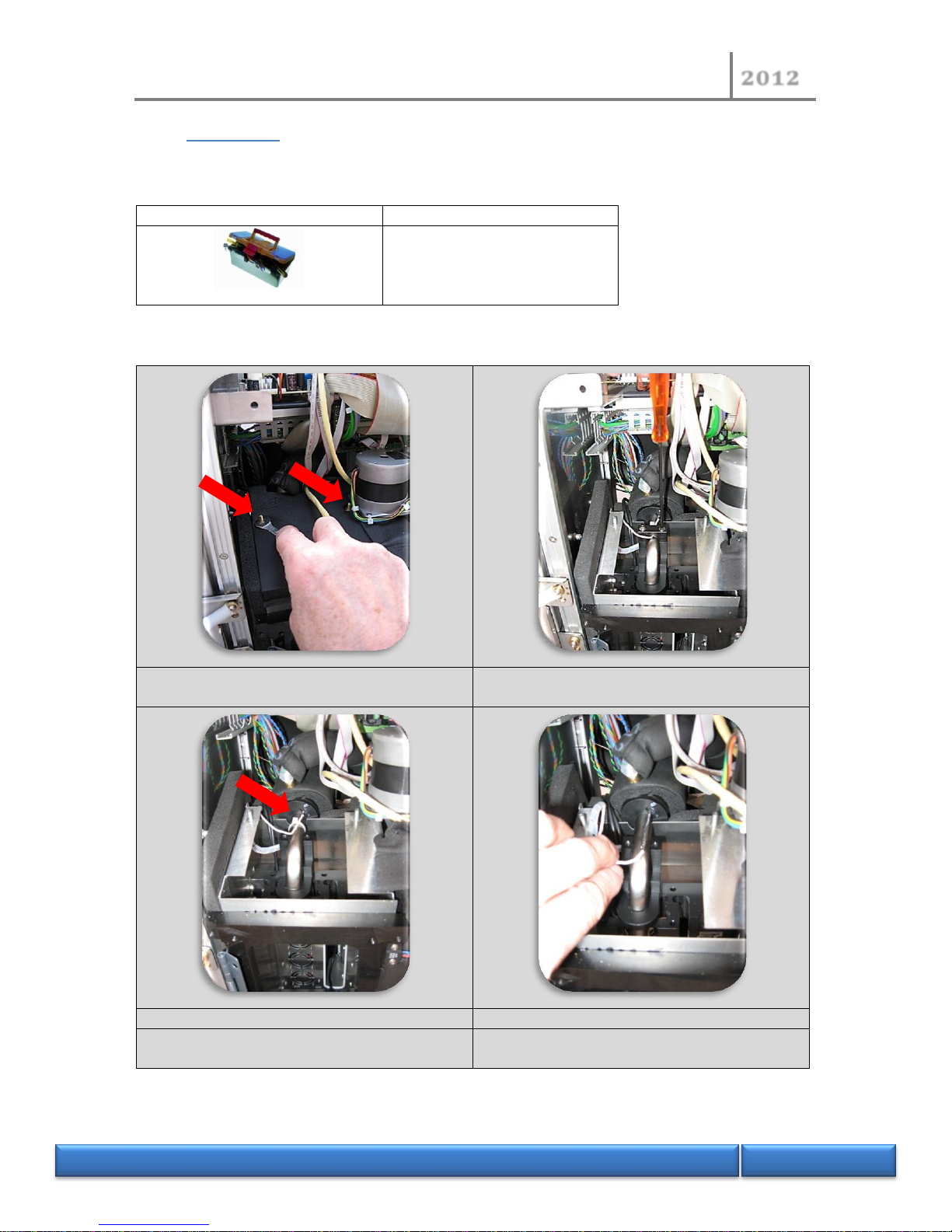
3.4 Condenser
3.4.1 Replacement condenser probe
Tools
1 hex head key 3 mm
1 wrench 7 mm
Remove the front panel (see above procedure 3.1.2)
Remove the roof of the compartment (2 screws)
and extract it ( take care at the insulation )
Loosen the 2 screws of the flange and deposit it
Cut the fixing collar probe
Extract the probe of the housing
Unplug the probe wires from CL2 board.
Connector J3 on 14/15 and 16/17
Do not forget to replace the new fixing collar to
lock the probe in housing
A checking of the calibration may be necessary (by simulation of probe)
Page 32
NORMALAB France
2012
N O R M A L A B F r a n c e
32/118
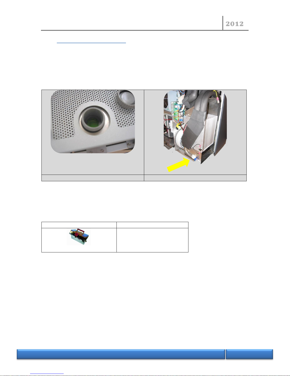
3.5 Cooling condenser system
3.5.1 Replacement or drain of the coolant liquid circuit
Remove the right and rear panels (see above procedure 3.1.1)
Open the cap of the expansion tank
Open the valve to drain
Note: The liquid volume to fill circuit is approximately 250 mL
3.5.2 Replacement of pump
Tools
1 hex head key 3 mm
1 wrench 7 mm
Remove the left and rear panels (see above procedure 3.1.1)
Drain the liquid circuit (see above procedure 3.5.1)
2 assembly types
Page 33
NORMALAB France
2012
N O R M A L A B F r a n c e
33/118
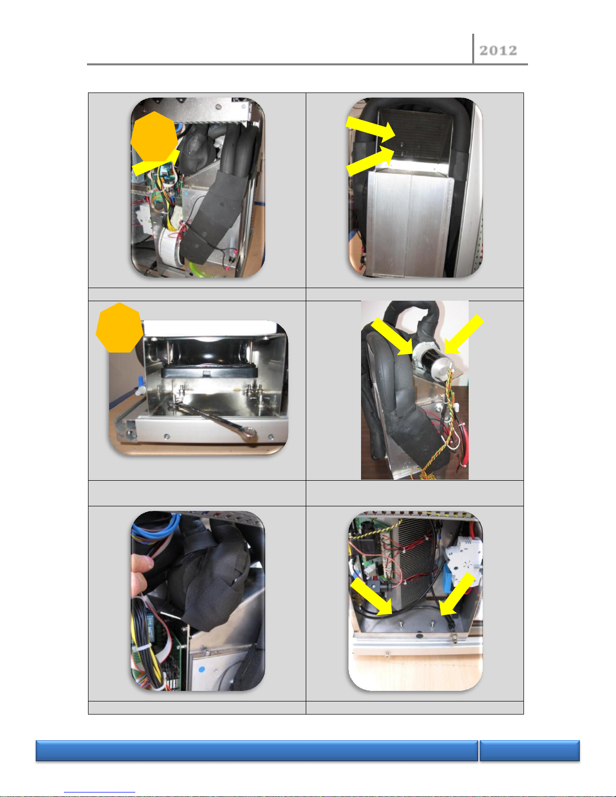
Position of the pump
Remove the 2 fixing screws
Or remove the 4 nuts and lift the assembly and
rotate it
And remove the 2 fixing screws of the pump
Remove insulation fitting and disconnect them
Remove the frame fixations
1
2
Page 34
NORMALAB France
2012
N O R M A L A B F r a n c e
34/118
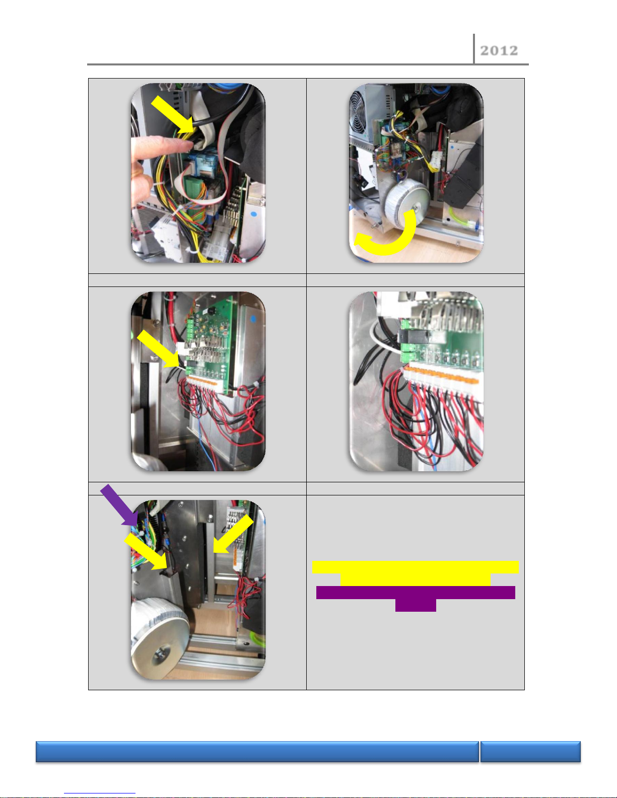
Remove the ribbons of CL3 board
Release the power supply frame on the left
Unplug the wires of the board
White wire in 1 and black wire on 2 of J10
At the reassembling ,properly position the frame
to match with amount of the frame
Beware the proper positioning of the bundle in
the notch
Page 35
NORMALAB France
2012
N O R M A L A B F r a n c e
35/118
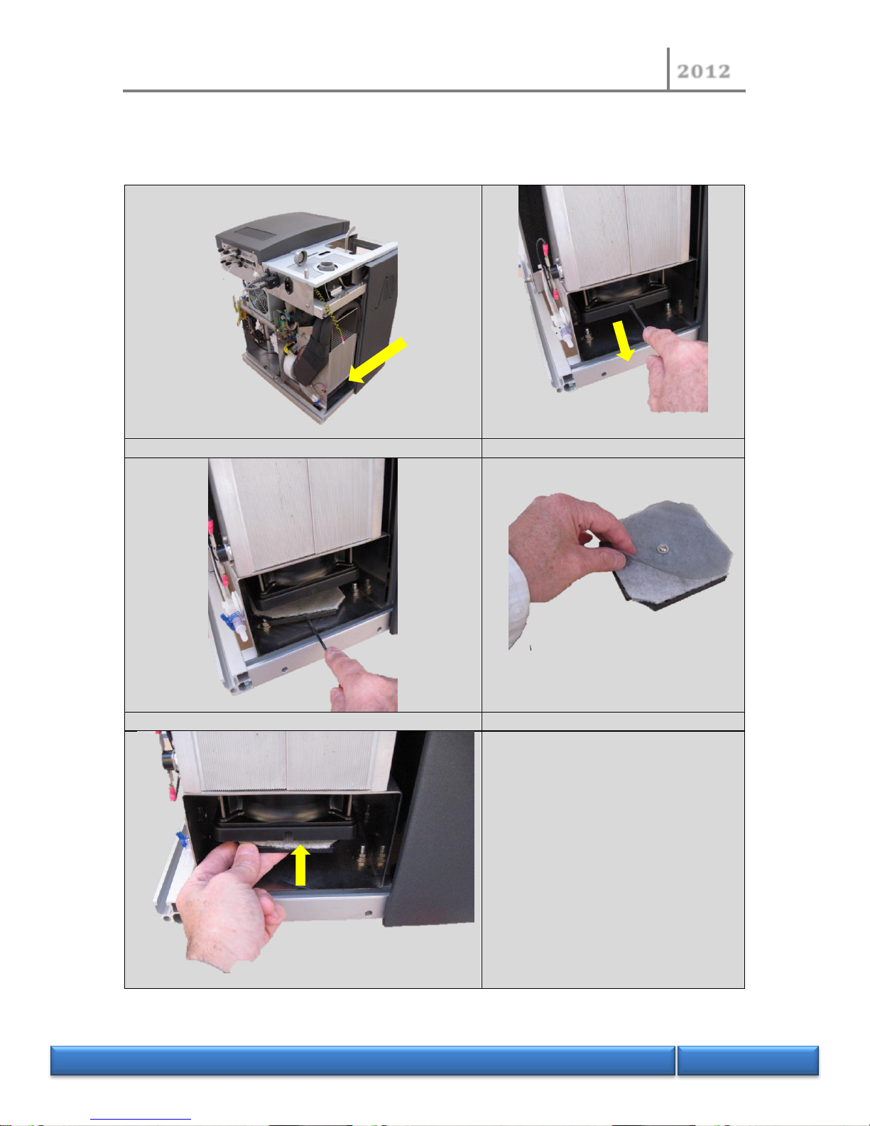
3.5.3 Replacement of filter or fan
Remove the side and rear panels (see above procedure 3.1.1)
Push down with blade of the screwdriver
To unclip the filter holder
Clean or replace the filter
Replace the filter holder with filter
Page 36
NORMALAB France
2012
N O R M A L A B F r a n c e
36/118
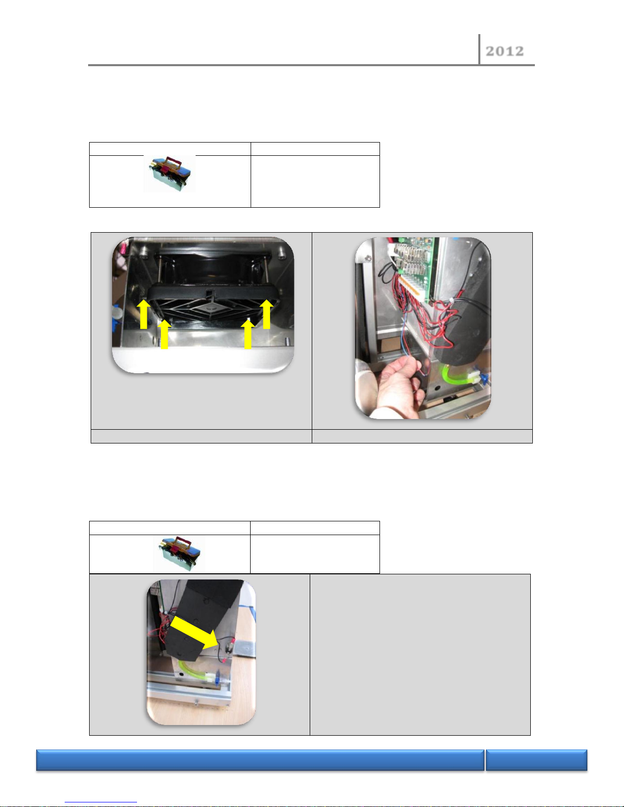
3.5.4 Replacement of fan
Remove the left panel (see above procedure 3.1.1)
Remove the filter holder (see above procedure 3.5.3)
Tools
1 screwdriver 3 mm
1 tube key 7 mm
Remove the 4 fixing nuts
Remove the power supply wires
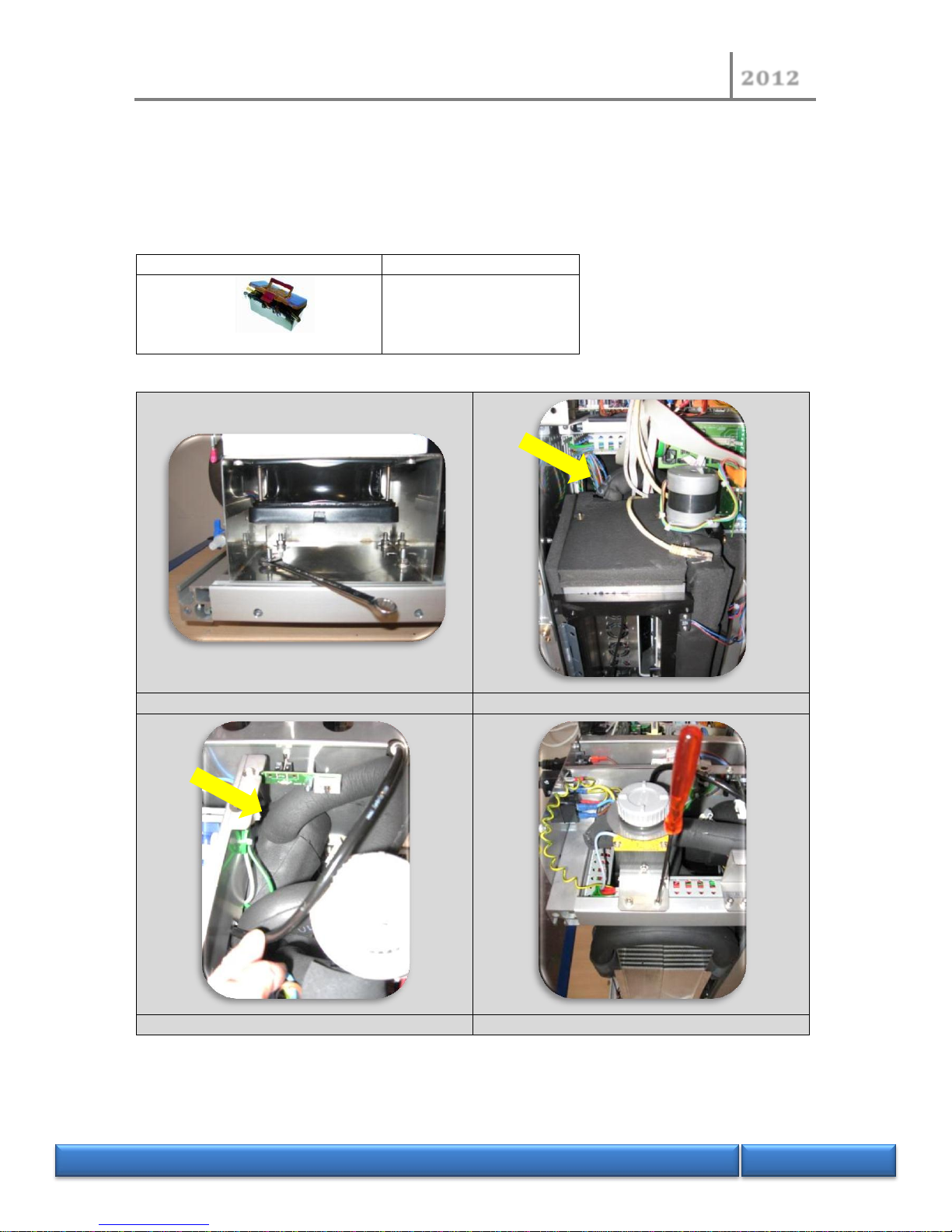
3.5.5 Replacement of fan speed thermostat
Remove the side and rear panels (see procedure 3.1.1)
Tools
1 hex head key 2.5 mm
Remove the 2 lugs
Remove the thermostat
Page 37
NORMALAB France
2012
N O R M A L A B F r a n c e
37/118
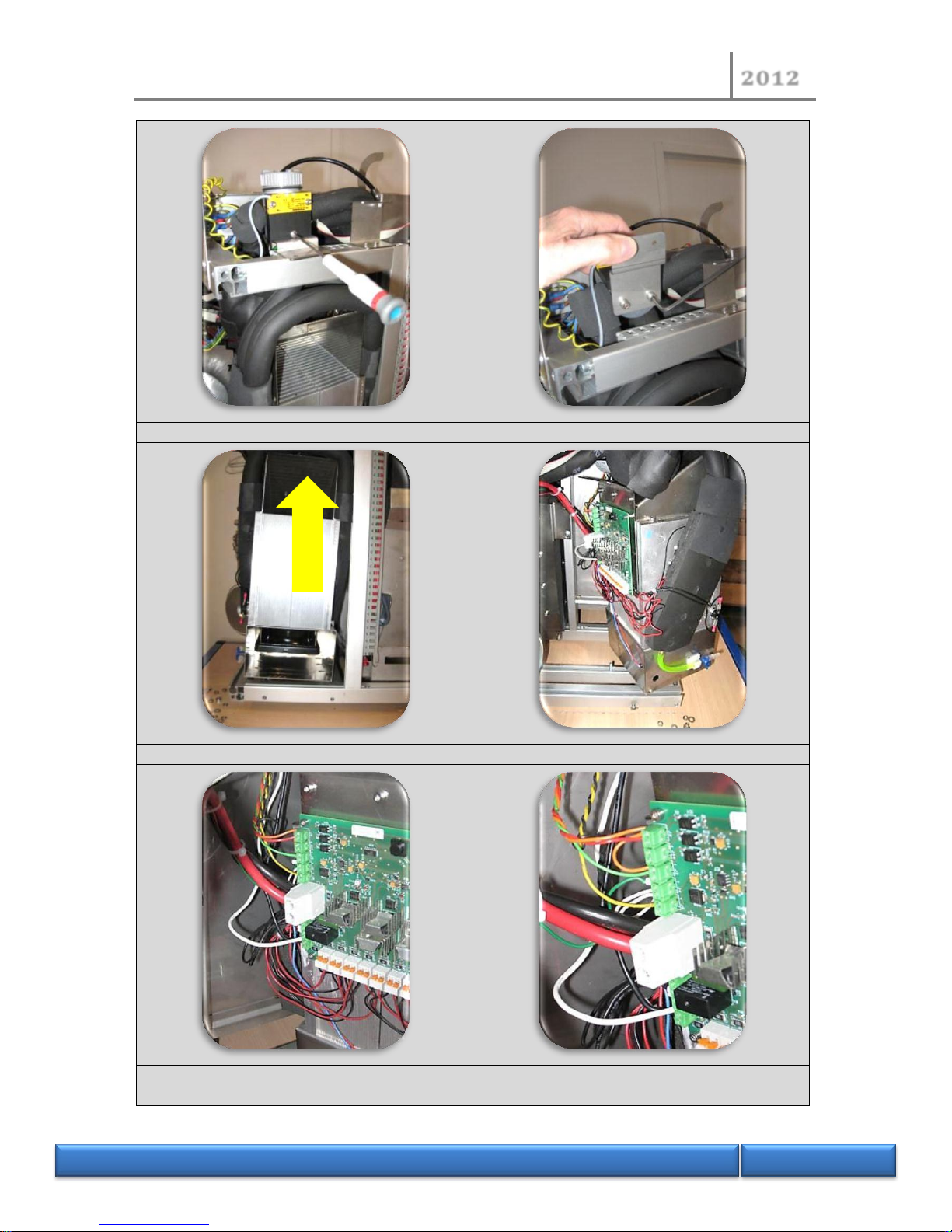
3.5.6 Replacement of Peltier subset
Remove the front panel (see above procedure 3.1.2)
Drain the liquid circuit (see above procedure 3.5.1)
Tools
1 wrench 10 mm
1 hex head key 3 mm
1 hex head key 2.5 mm
Remove the 4 fixing nuts
Unplug the low fitting of condenser
Unplug the high fitting of condenser
Remove the expansion tank
Page 38
NORMALAB France
2012
N O R M A L A B F r a n c e
38/118
Remove the level detector ( 3 screws)
Remove the tank
Raise the assembly to release the 4 studs
Release the assembly to unplug the pilot wires
Unplug the pilot wires : orange , red , green and
yellow
Page 39
NORMALAB France
2012
N O R M A L A B F r a n c e
39/118
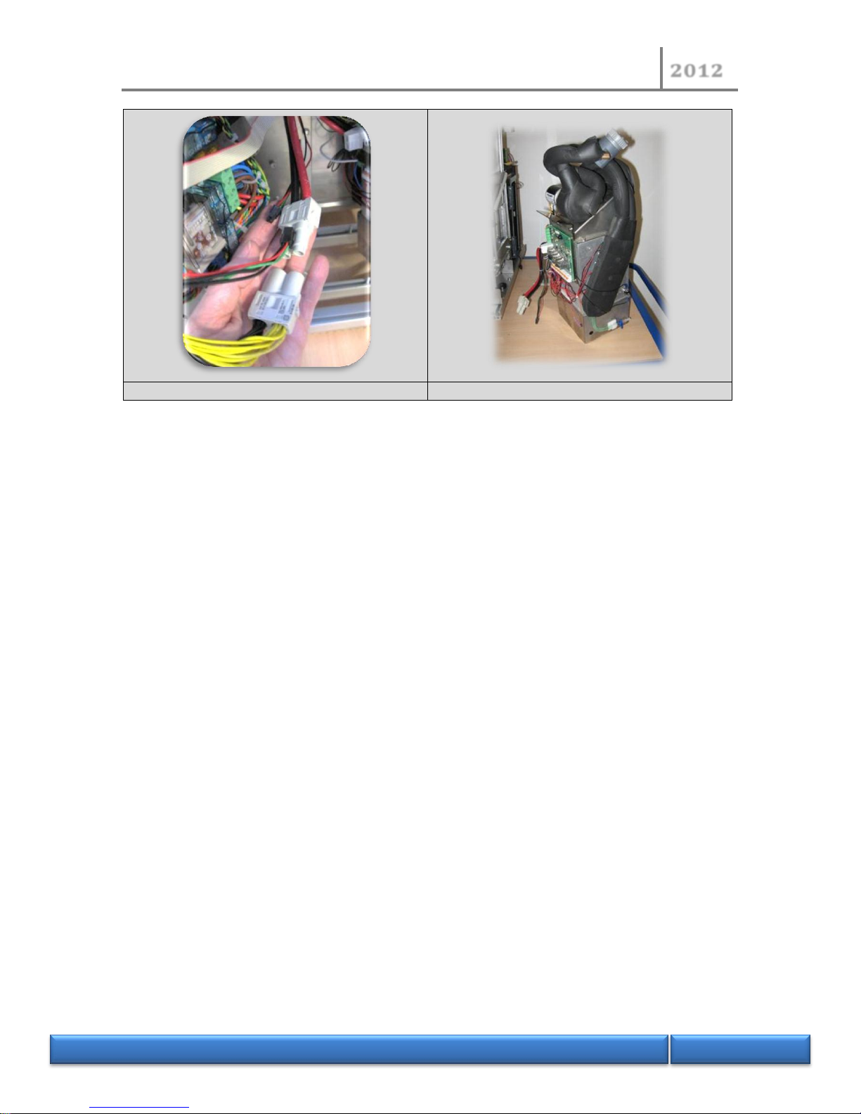
Unplug the power supply wires
Extract the assembly
Page 40
NORMALAB France
2012
N O R M A L A B F r a n c e
40/118
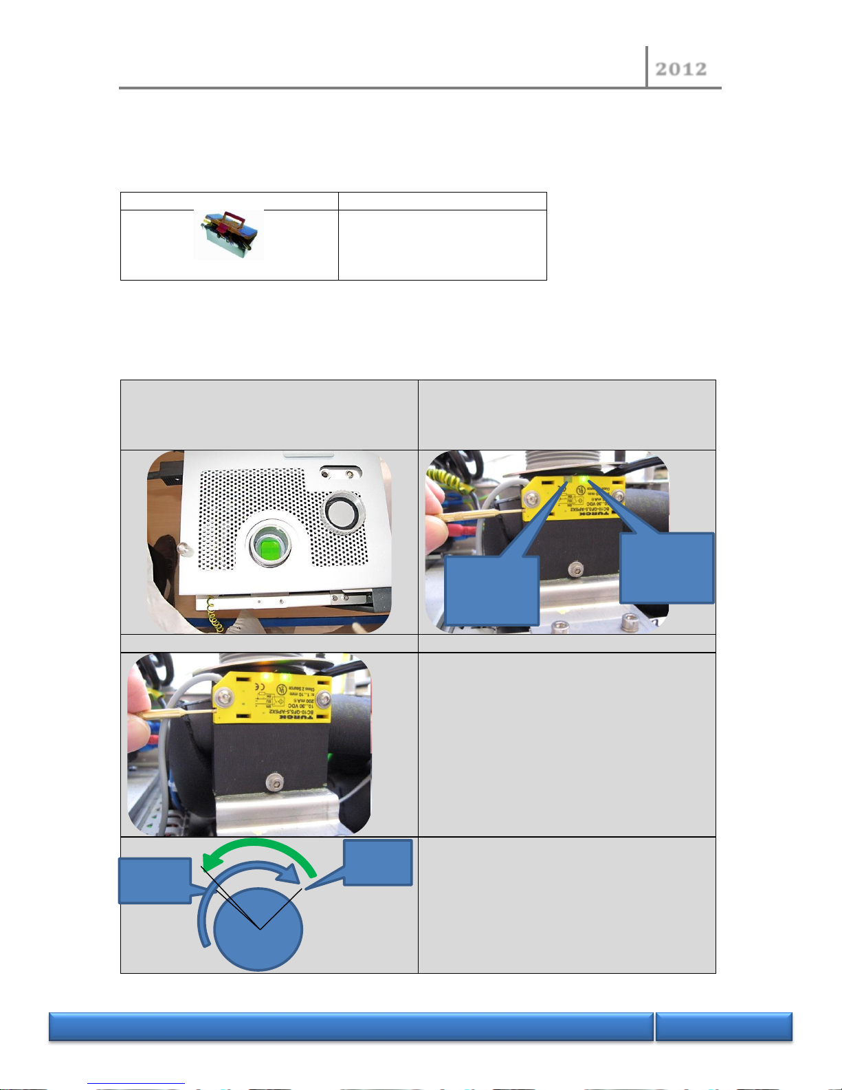
3.5.7 Adjustment or replacement of the liquid level detector
Tools
1 hex head key 2.5 mm
1 screwdriver 1.5 mm
Remove the side and rear panels (see above procedure 3.1.1)
Remove the 3 fixing screws of sensor
Remove the wires on J7 of CL3 Board
Wires connections :
- Brown 5 on J7 CL3
- Black 6 on J7 de CL3
- Blue 7 on J7 de CL3
Low level detection
Sensitivity adjustment
Turn the sensitivity screw to switch on the lamp
and go back just before extinction
1°) Find the threshold point to switch on and
extinction lamp
2°) Repeat the operation and stop adjustment
just before extinction point
Power
supply lamp
Detection
lamp
Switch on
point
Extinction
point
Page 41
NORMALAB France
2012
N O R M A L A B F r a n c e
41/118
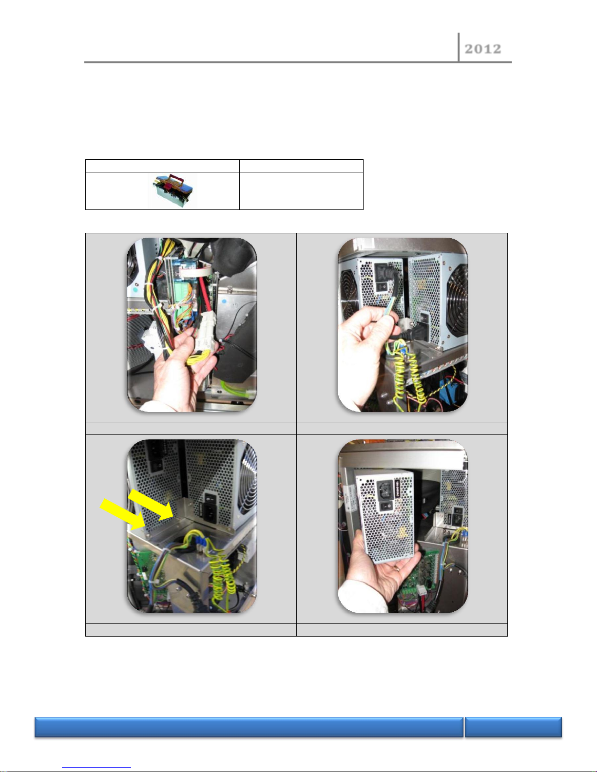
3.5.8 Replacement of subset Peltier power supply
Remove the right and rear panel (see above procedure 3.1.1)
Tools
1 cross tip screwdriver
Unplug the power supply wires
Unplug the main supply wires
Remove the 2 screws
Remove the power supply
Page 42
NORMALAB France
2012
N O R M A L A B F r a n c e
42/118
3.6 Compartment cooling system
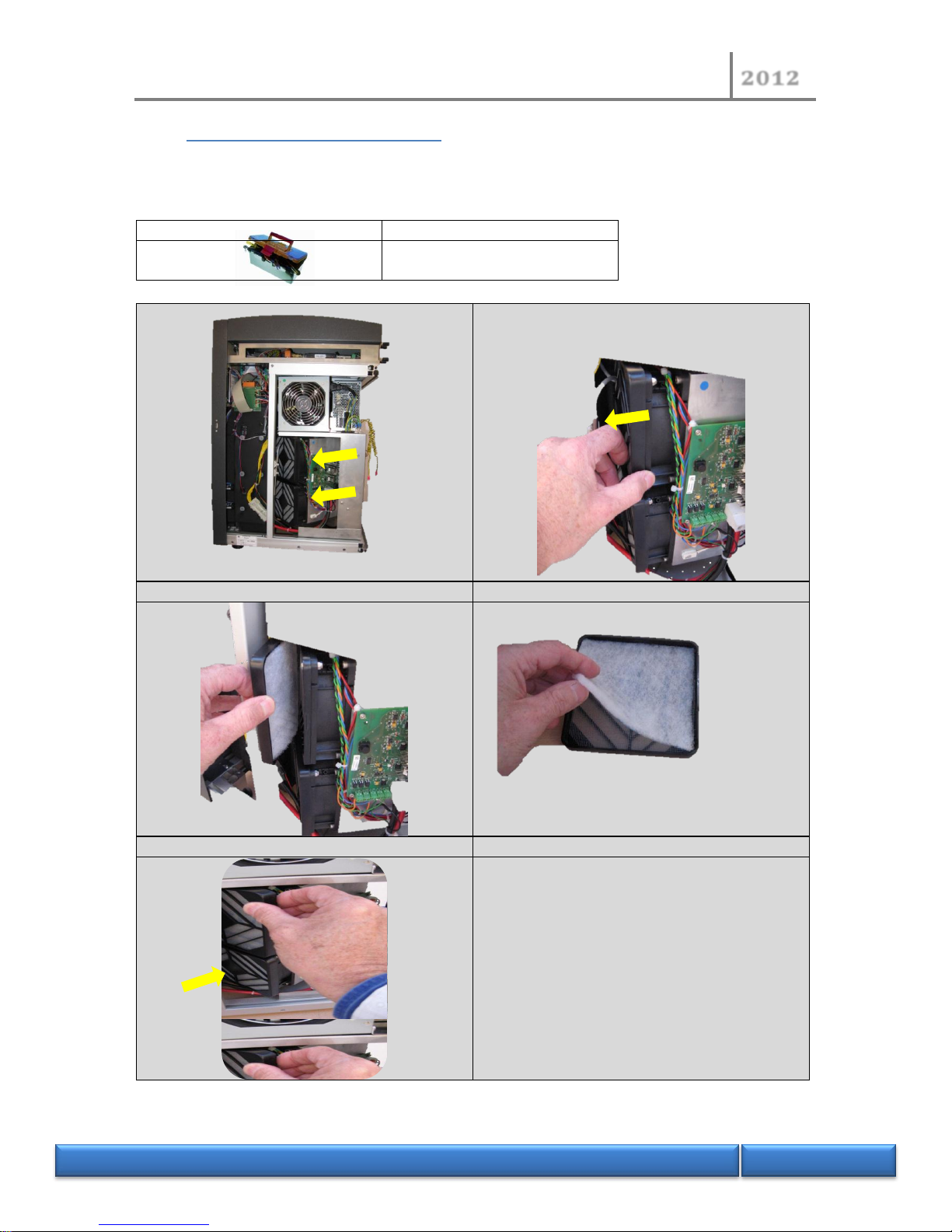
3.6.1 Replacement of the filters or fans
Remove the right and rear panel (see above procedure 3.1.1)
Tools
1 screwdriver 3.5 mm
Position of filters and fans
Pull the filter holder to unclip
Release the filter in fiber
Clean or replace it
Replace the filter and his holder
Page 43
NORMALAB France
2012
N O R M A L A B F r a n c e
43/118
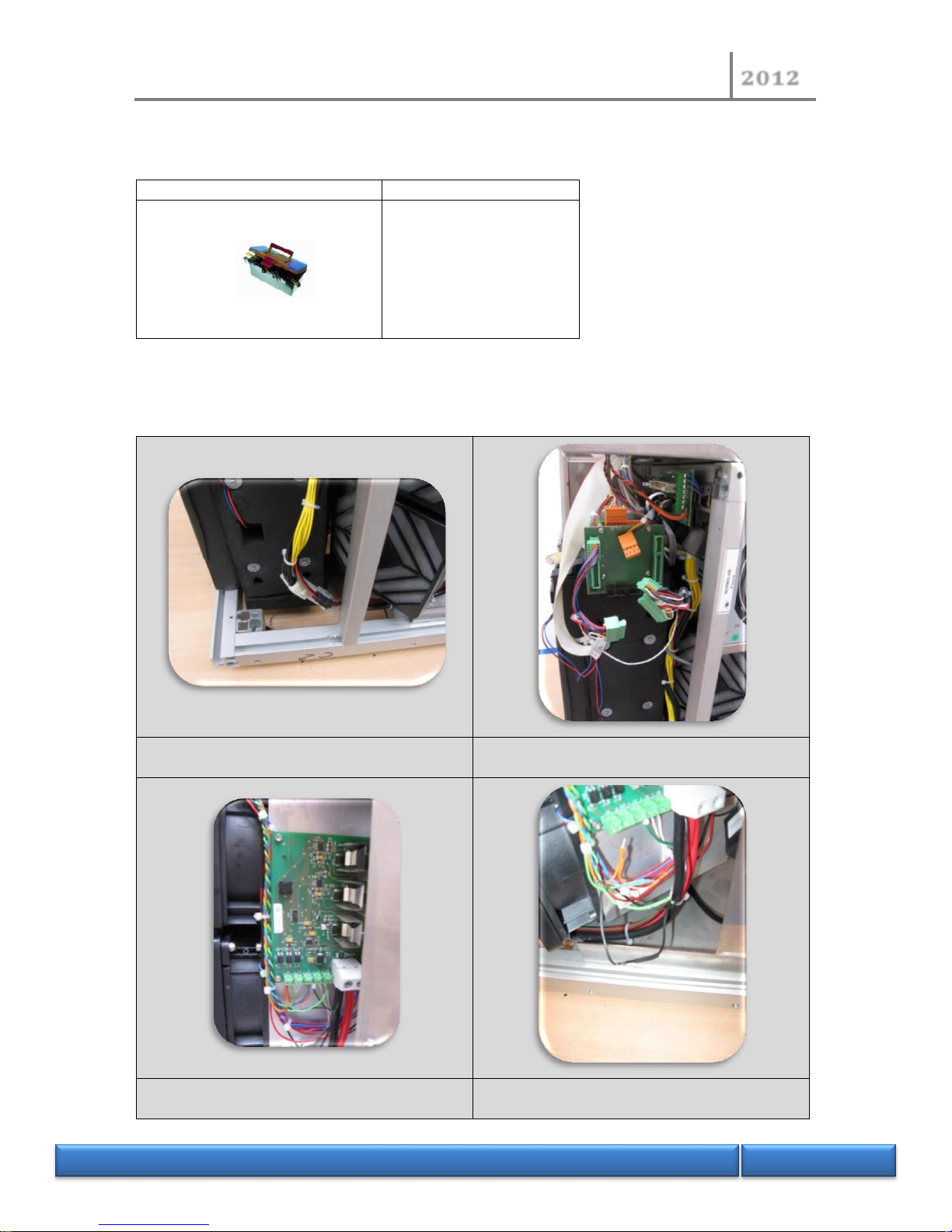
3.6.2 Replacement of the Peltier subset of receiver compartment
Tools
1 screwdriver 2.5 mm
1 iron solder
1 cutting plier
1 wrench 7 mm
1 wrench 10 mm
Remove the side and rear panels (see above procedure 3.1.1)
Remove the front panel (see above procedure 3.1.2)
Unplug the power supply wires
Remove the connectors from CL2 board and
motor board
Unplug the pilot wire and de-soldering the black
wire
Page 44
NORMALAB France
2012
N O R M A L A B F r a n c e
44/118
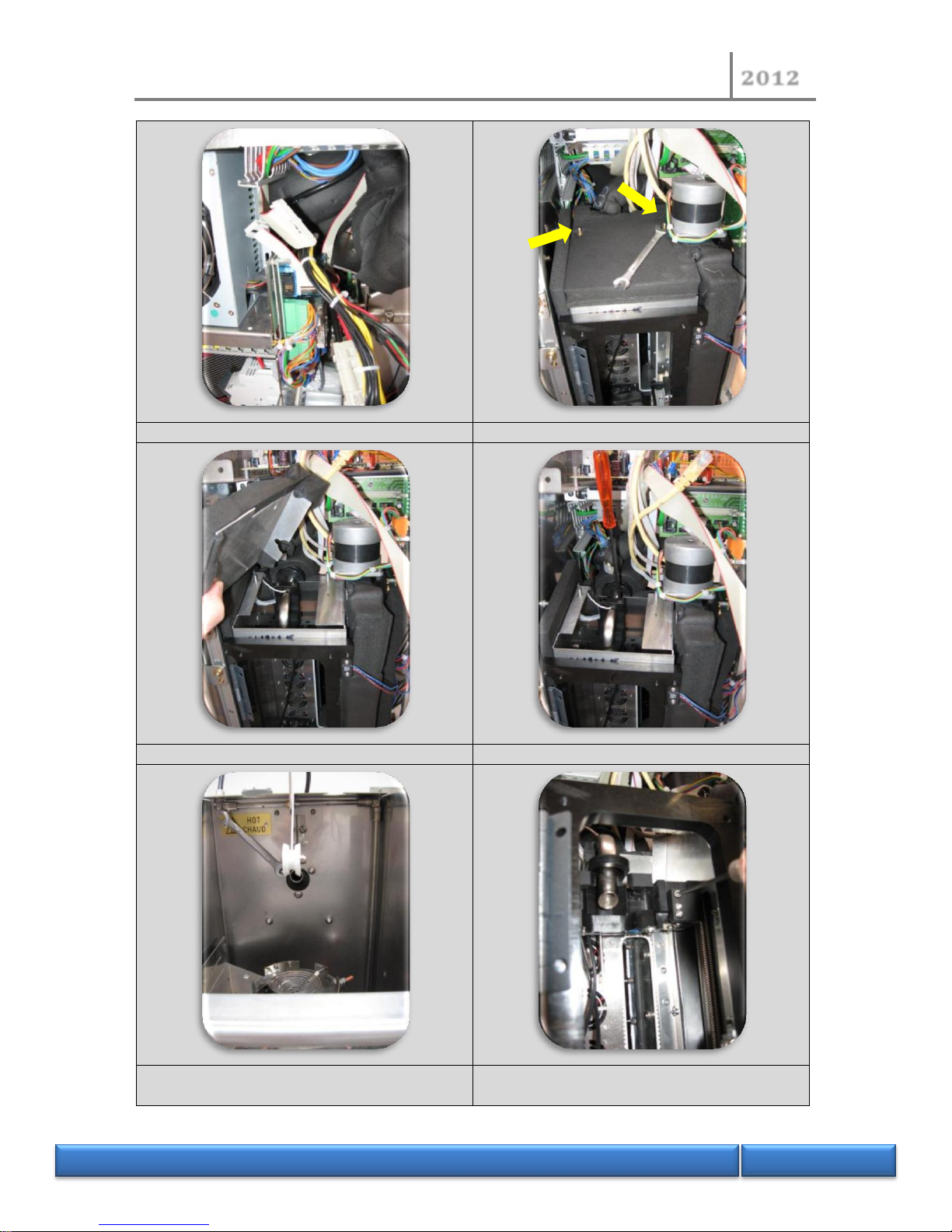
Unplug the 2 ribbons of CL3 board
Remove the roof of the compartment
Extract the roof
Remove the flange of condenser
Remove the condenser fixing in the heating
block part of condenser ( 3 screws)
Remove the first drop optical sensor
Page 45
NORMALAB France
2012
N O R M A L A B F r a n c e
45/118
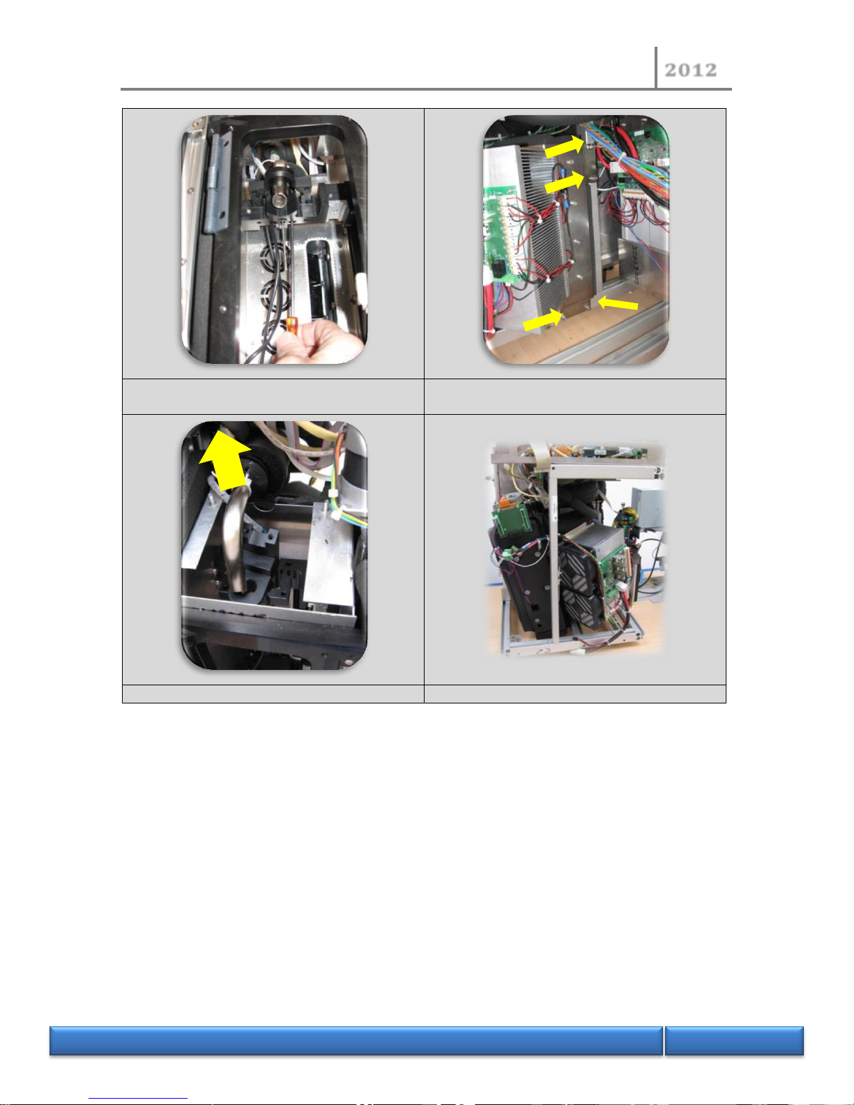
Remove the centering condenser in
compartment
Remove the 4 fixing screws of subset
Release the centering condenser
Extract the subset by forward rotation
Page 46
NORMALAB France
2012
N O R M A L A B F r a n c e
46/118
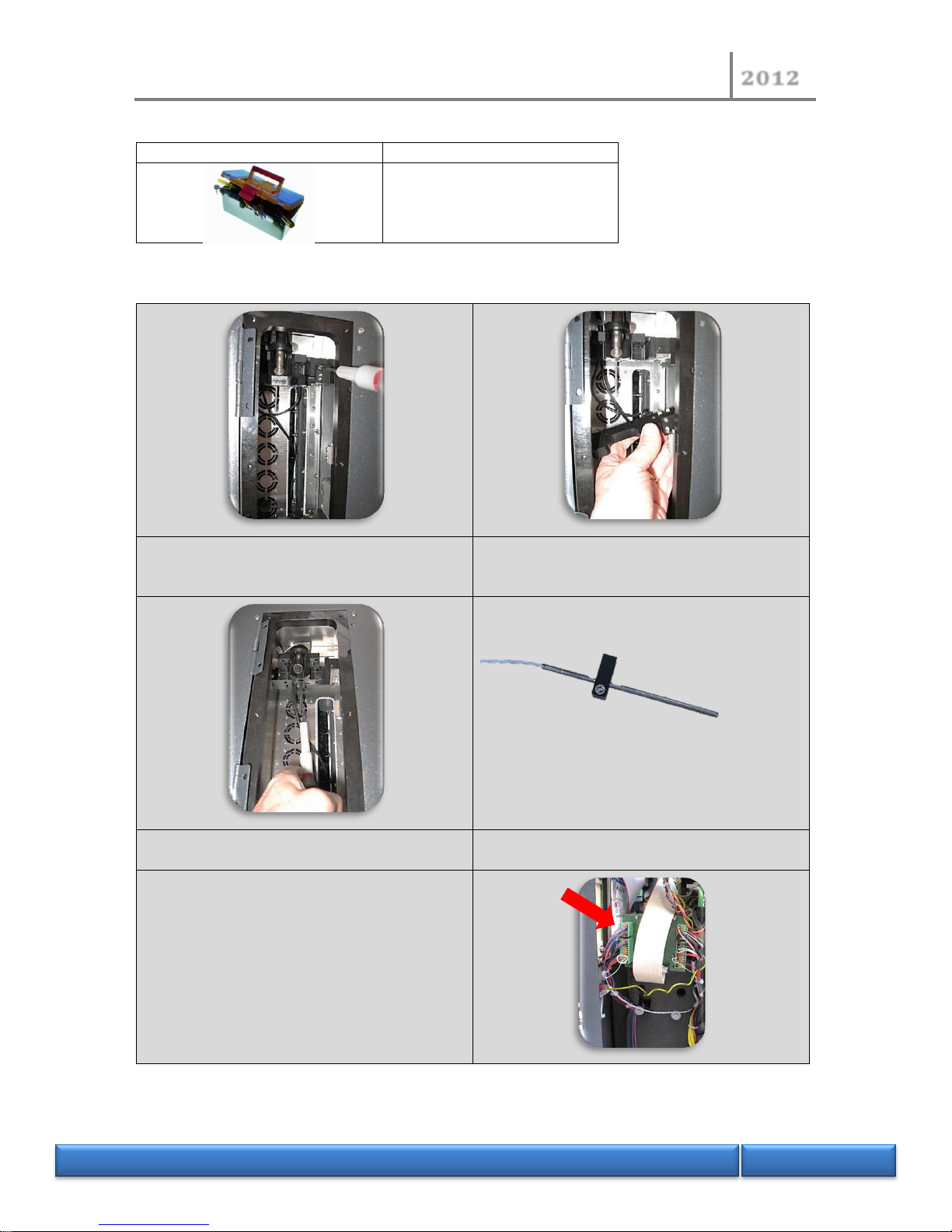
3.6.3 Replacement of the compartment probe
Tools
1 hex head key 2.5 mm
Remove the side and rear panels (see above procedure 3.1.1)
Remove the front panel (see above procedure 3.1.2)
Remove the first drop sensor ( without
modifying the adjustment) see procedure 3.2.1)
Unplug the sensor
Remove the flange of the probe
Recover the probe ring to place it in the new one
( at 50 mm from the probe tip)
The wires are on 13-14 and 15-16 of J1
connector
The check of calibration may be necessary
Page 47
NORMALAB France
2012
N O R M A L A B F r a n c e
47/118
3.6.4 Replacement of subset Peltier power supply
See above procedure 3.5.8
3.7 Chassis
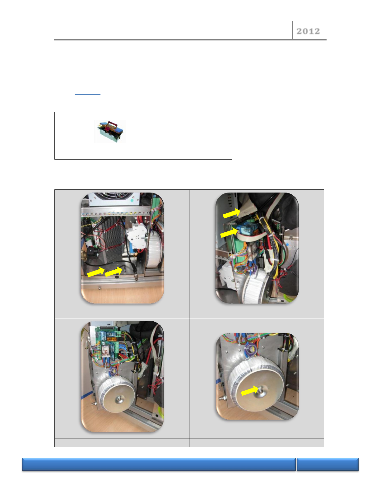
3.7.1 Replacement of the heating transformer
Tools
1 screwdriver 3.5 mm
1 hex head key 5.5 mm
1 hex head key 5 mm
1 wrench 12 mm
Remove the side and rear panels (see above procedure 3.1.1)
Remove the fixing screws of power supply frame
Remove the 2 ribbons of CL3 board
Release by rotation the supply frame
Unplug the transformer and remove it
Page 48
NORMALAB France
2012
N O R M A L A B F r a n c e
48/118
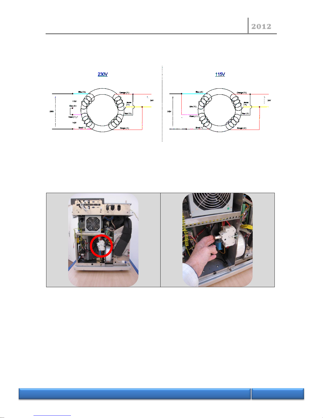
Coupling transformer
3.7.2 Replacement of the heating fuse
Remove the side and rear panel (see above procedure 3.1.1)
Page 49
NORMALAB France
2012
N O R M A L A B F r a n c e
49/118
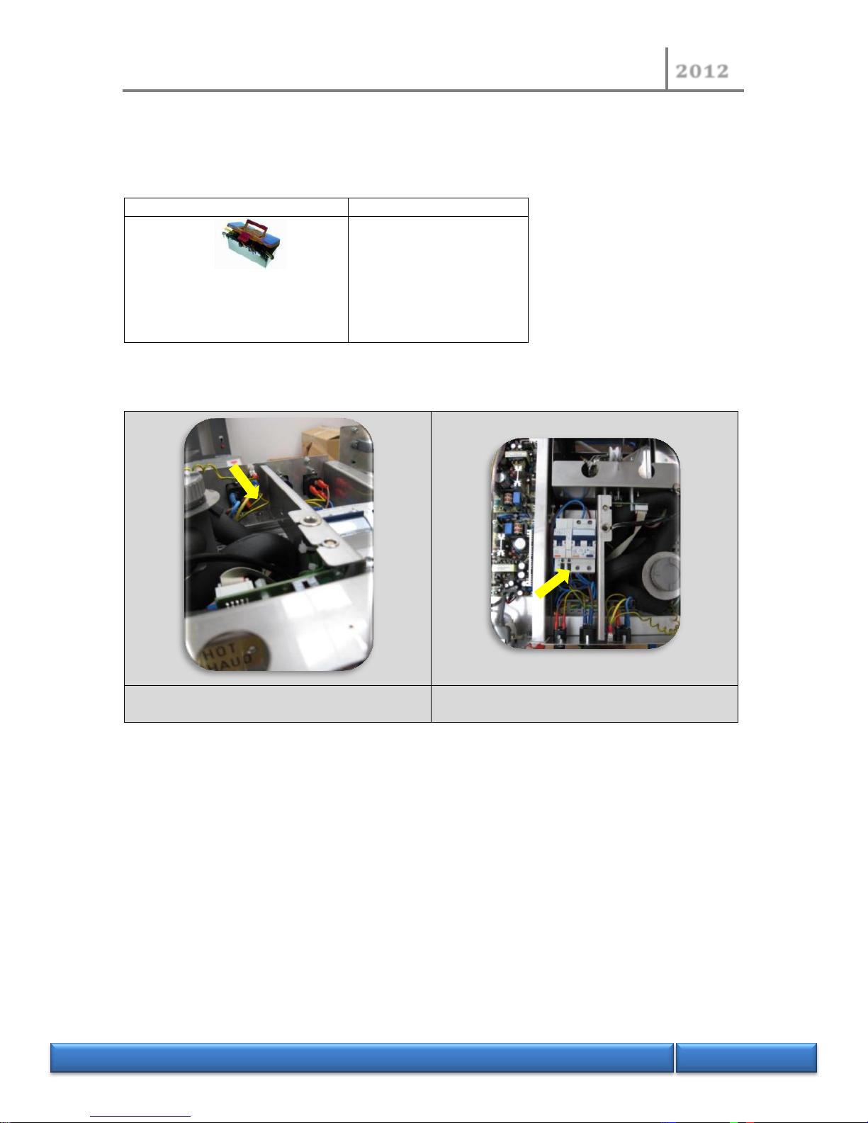
3.7.3 Replacement of the circuit breaker
Tools
1 screwdriver 2.5 mm
1 iron solder
1 cutting pliers
1 wrench 7 mm
1 wrench 10 mm
Remove the left upper panel (see above procedure 3.1.3)
Remove the circuit breaker holder
Unplug the wires and remove the circuit breaker
by pulling the tab
Page 50
NORMALAB France
2012
N O R M A L A B F r a n c e
50/118
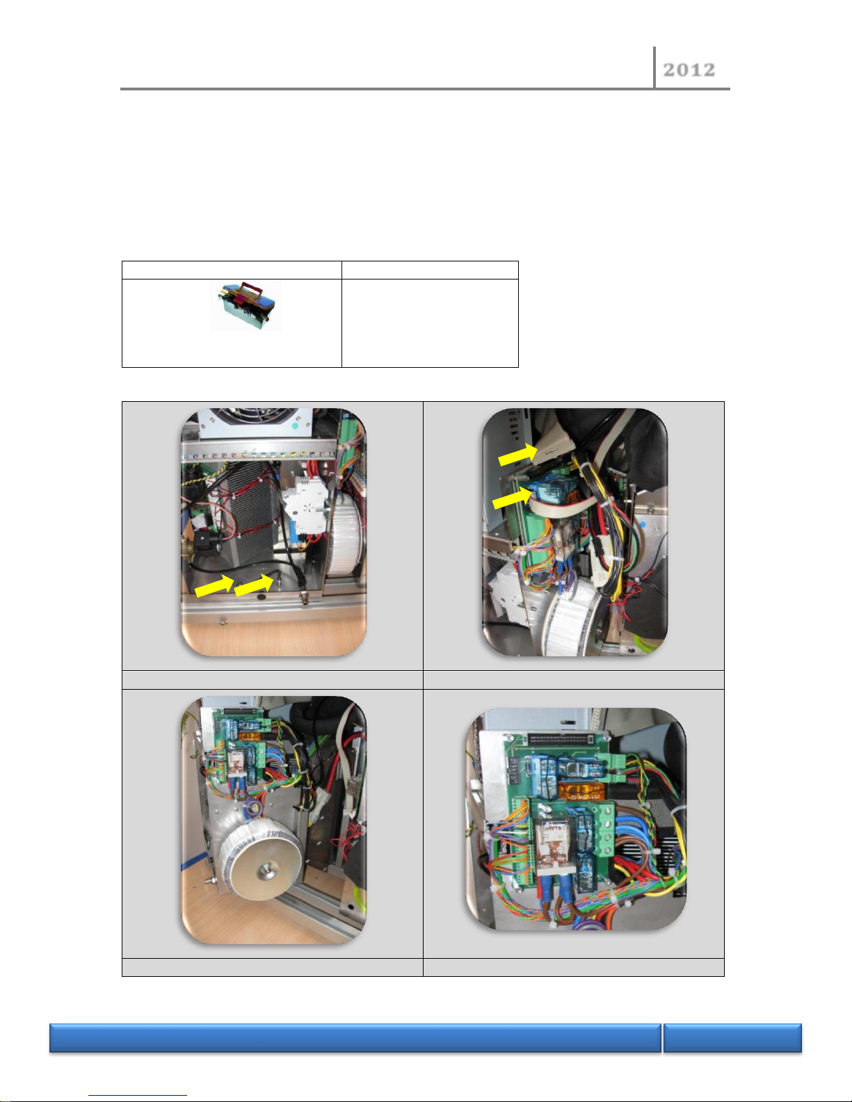
3.7.4 Replacement of the CL3 board
Remove the side and rear panels (see above procedure 3.1.1)
Tools
1 hex head key 5.5 mm
1 tube key 5.5 mm
1 wrench 12 mm
Remove the fixing supply frame
Remove the 2 ribbons of CL3 board
Unplug the wires of the board
Remove the 4 fixing nuts of the board
Page 51
NORMALAB France
2012
N O R M A L A B F r a n c e
51/118
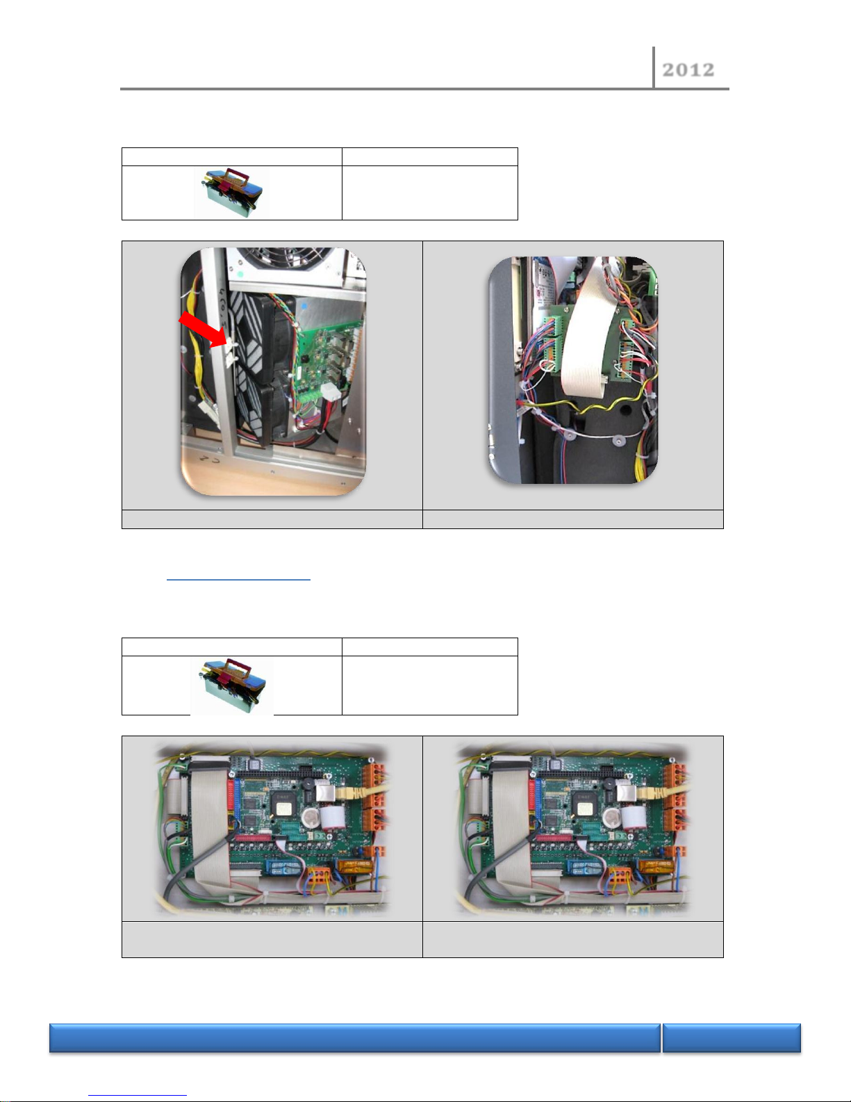
3.7.5 Replacement of the ambient probe
Remove the side and rear panels (see above procedure 3.1.1)
Tools
1 hex head key 2.5 mm
1 tube key 5.5 mm
The probe is fixed with 2 collars
Unplug the wires on 10-11 and 12-13 of J3
The check of calibration may be necessary
3.8 Electronic drawer
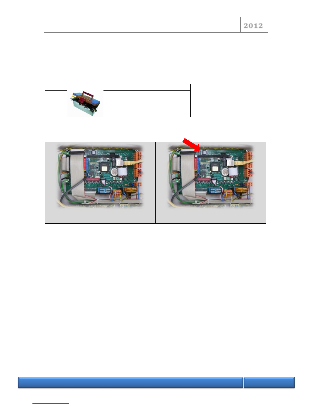
3.8.1 Replacement of the CL1 board
Remove the left upper panel (see above procedure 3.1.3)
Tools
1 hex head key 4 mm
1 tube key 5.5 mm
1 screwdriver 3.5 mm
Remove the connections and disconnect the
pressure sensor
Remove the CPU
Page 52
NORMALAB France
2012
N O R M A L A B F r a n c e
52/118
3.8.2 The barometric sensor
Remove the left upper panel (see above procedure 3.1.3)
Tools
1 hex head key 4 mm
1 tube key 5.5 mm
1 screwdriver 3.5 mm
Remove the connections and disconnect the
pressure sensor
The barometric sensor is welded on SMD , see
procedure for removing CL1 board
Page 53
NORMALAB France
2012
N O R M A L A B F r a n c e
53/118
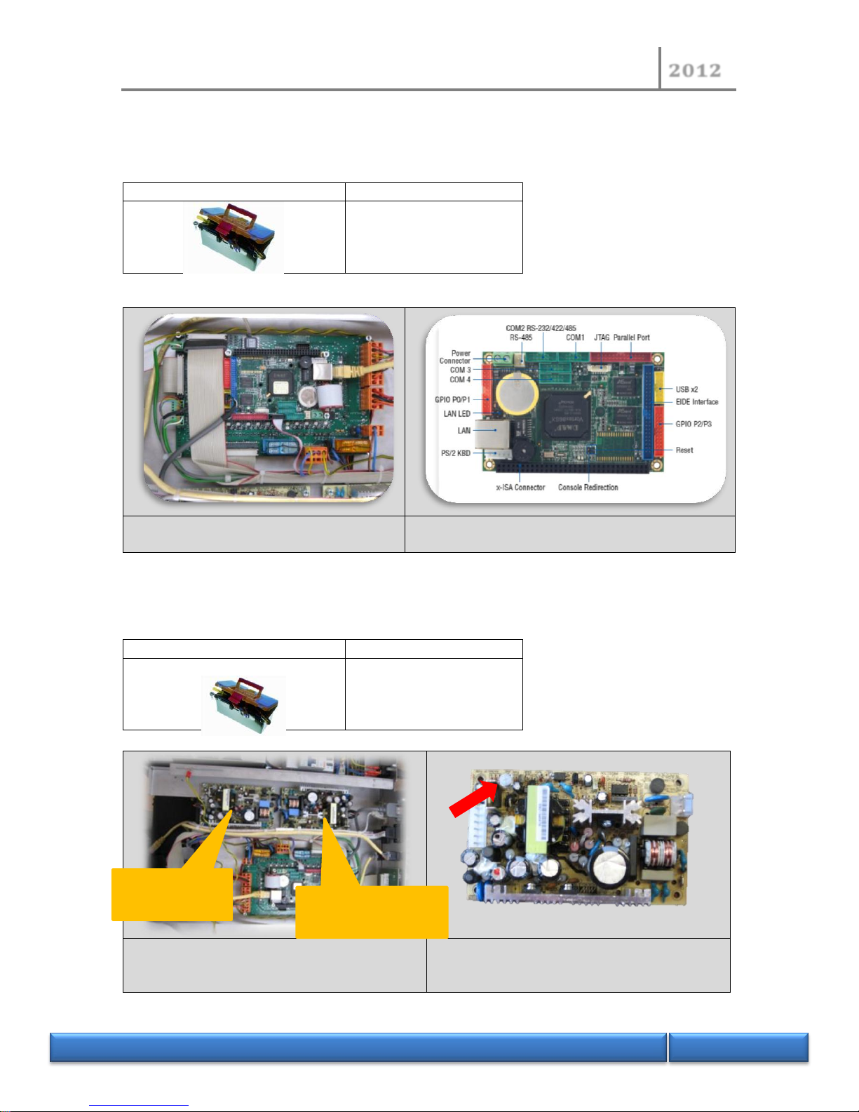
3.8.3 Replacement process of the microprocessor board
Tools
1 hex head key 2.5 mm
1 tube key 5.5 mm
Remove the left upper panel (see above procedure 3.1.3
The CPU is mounted in mezzanine on the CL1
board
The new CPU must be preloaded with the NDI
process version
3.8.4 Replacement of the power supply of UC board or step by step motor
Remove the left upper panel (see above procedure 3.1.3
Tools
1 hex head key 2.5 mm
1 iron soldering and
welding
De-soldering power supply wires and the power
supply output
Put the new power supply and check the 5V on
the CPU terminal. For stepper motor board , it is
better to adjust the voltage at 5.2 V
CPU power
supply
Stepper motor power
supply
Page 54
NORMALAB France
2012
N O R M A L A B F r a n c e
54/118
3.9 Front panel
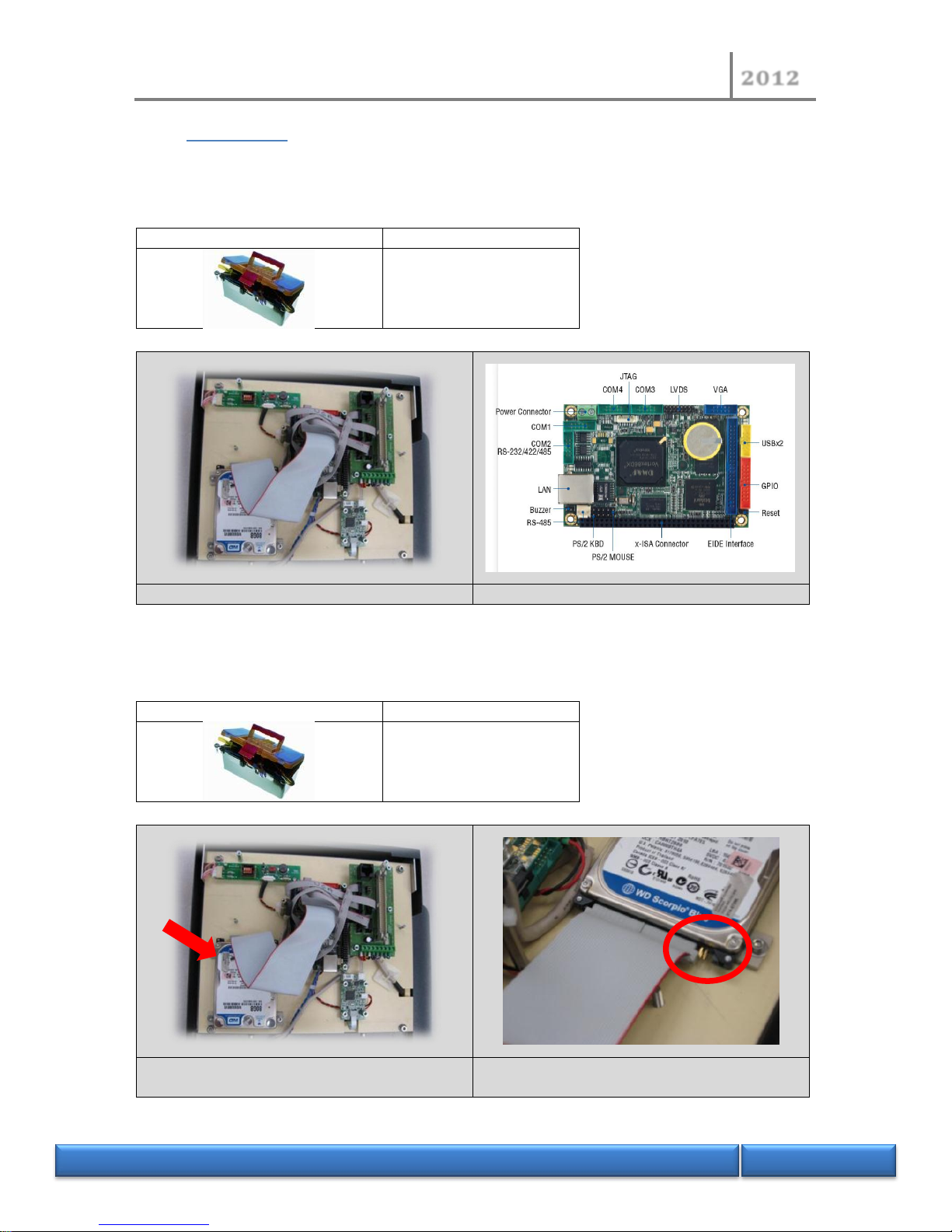
3.9.1 Replacement of MMI microprocessor board
Remove the side and rear panels (see above procedure 3.1.1)
Remove the front panel (see above procedure 3.1.2)
Tools
1 screwdriver 2.5 mm
1 tube key 5.5 mm
Remove the connections and remove the CPU
3.9.2 Replacement of the hard drive disk
Remove the side and rear panels (see above procedure 3.1.1)
Remove the front panel (see above procedure 3.1.2)
Tools
1 screwdriver 2.5 mm
1 tube key 5.5 mm
Remove the connections and remove the hard
drive disk
Take care at the red mark of the ribbon and the
pin out of hard drive disk connector
Page 55
NORMALAB France
2012
N O R M A L A B F r a n c e
55/118
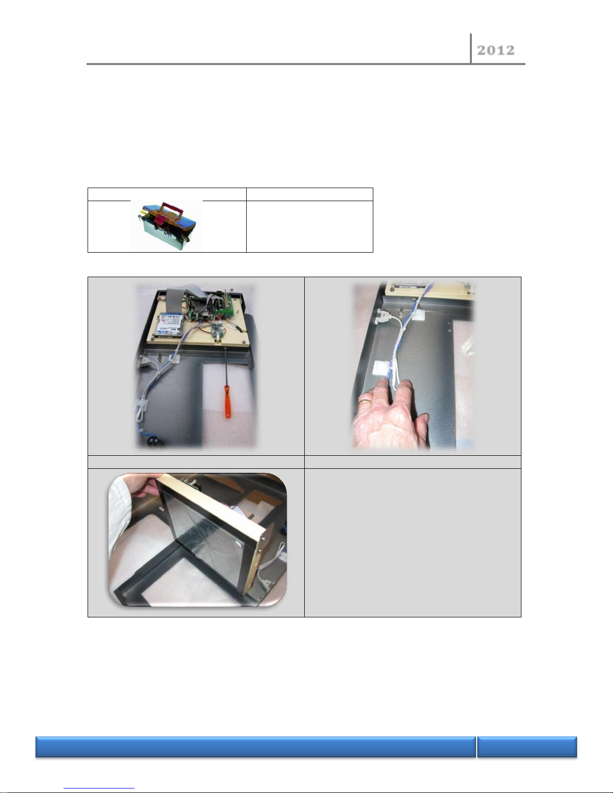
3.9.3 Replacement of the LCD display
Remove the side and rear panels (see above procedure 3.1.1)
Remove the front panel (see above procedure 3.1.2)
Tools
1 hex head key 2.5 mm
Remove the 2 fixing screws
Release the cable
Extract the LCD subset
Page 56
NORMALAB France
2012
N O R M A L A B F r a n c e
56/118
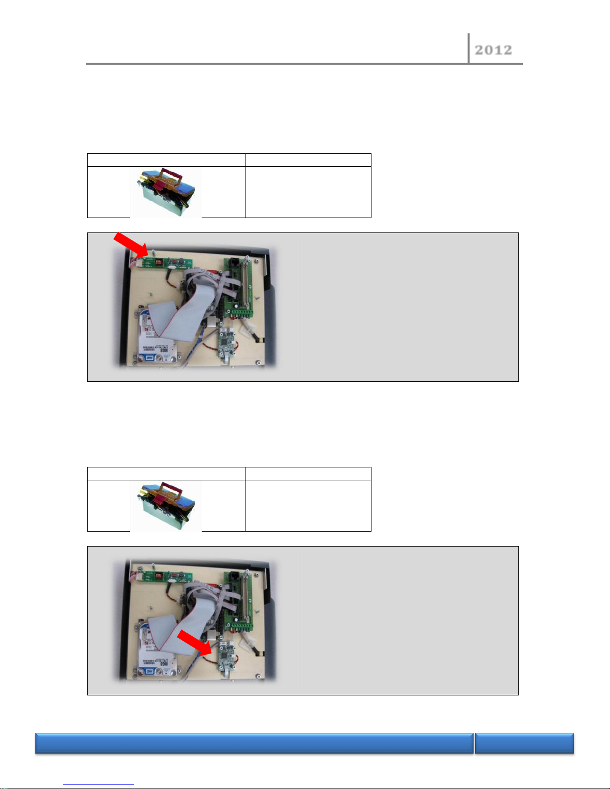
3.9.4 Replacement of inverter backlight
Remove the side and rear panels (see above procedure 3.1.1)
Remove the front panel (see above procedure 3.1.2)
Tools
1 screwdriver 2.5 mm
1 tube key 5.5 mm
Remove the connection and remove the inverter
3.9.5 Replace the touch screen controller
Remove the side and rear panels (see above procedure 3.1.1)
Remove the front panel (see above procedure 3.1.2)
Tools
1 screwdriver 2.5 mm
1 tube key 5.5 mm
Remove the connection and remove the
controller
Page 57
NORMALAB France
2012
N O R M A L A B F r a n c e
57/118
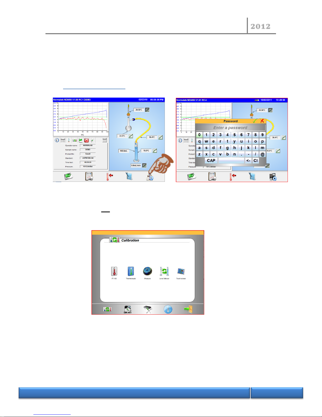
4 CALIBRATION AND MAINTENANCE FUNCTIONS
4.1 Calibration functions
Enter the password.
NB: on delivery of the instrument, the password is 0000.
There are 3 options for calibrating the instrument:
- Calibrating the complete measuring system (probe and electronics)
- Simulating the probe using a decade resistor or a calibrator (this method allows
calibrating exclusively the electronics, the probe error is thus not taken into account).
- Calibration by point (which allows entering the former calibration values to replace any
missing or erroneous values).
Page 58
NORMALAB France
2012
N O R M A L A B F r a n c e
58/118
Calibration of the complete system is the most accurate system since it incorporates the probe error
in the calibration to offset it. As a result, the probe must be mobile and two calibration baths
stabilised at precisely known temperatures are required. This method is reserved for the sample
probe (the other probes internal to the instrument are not mobile and their calibration does not
require such accuracy).
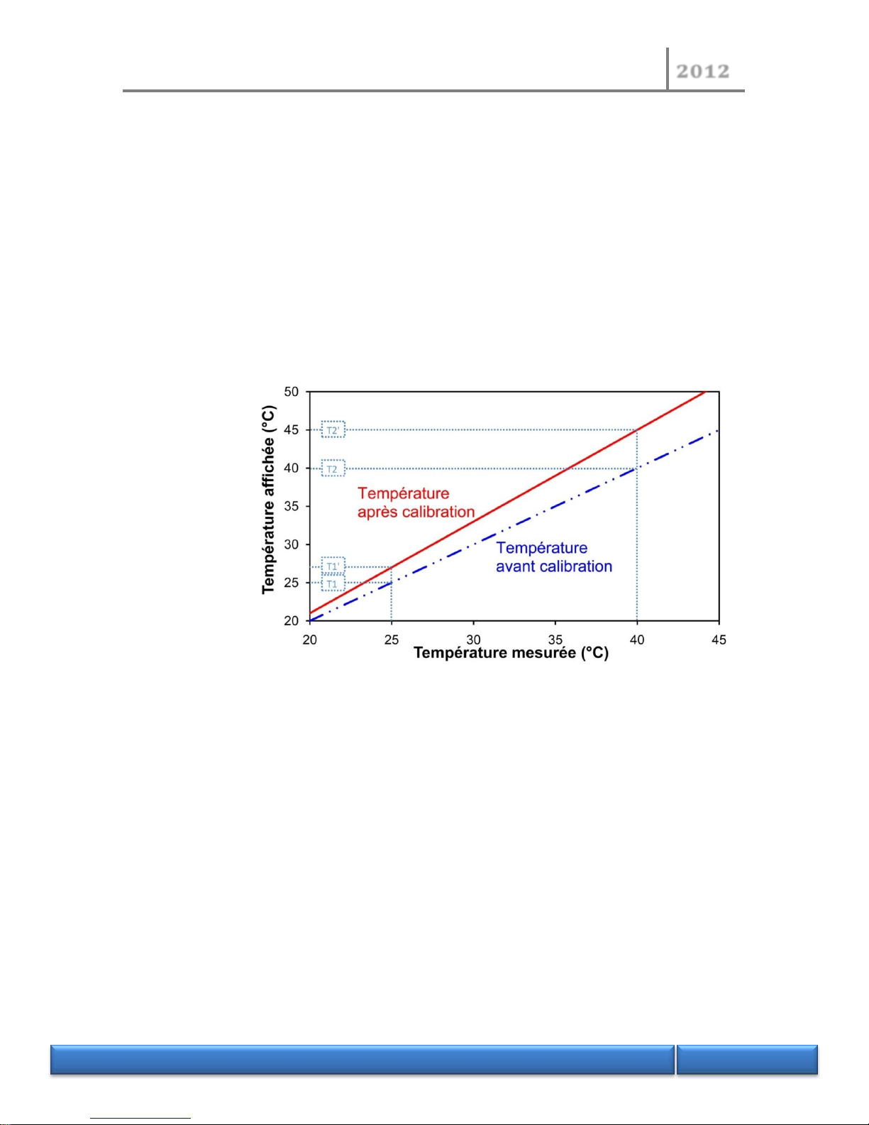
Calibration using two points adjusts the high point and the low point and defines a line interpolated
between them. Each reading above and below the calibration points will be an extension of the
interpolation line. For this reason, it is preferable to calibrate with two points as far away as possible
as shown in the example below.
Page 59
NORMALAB France
2012
N O R M A L A B F r a n c e
59/118
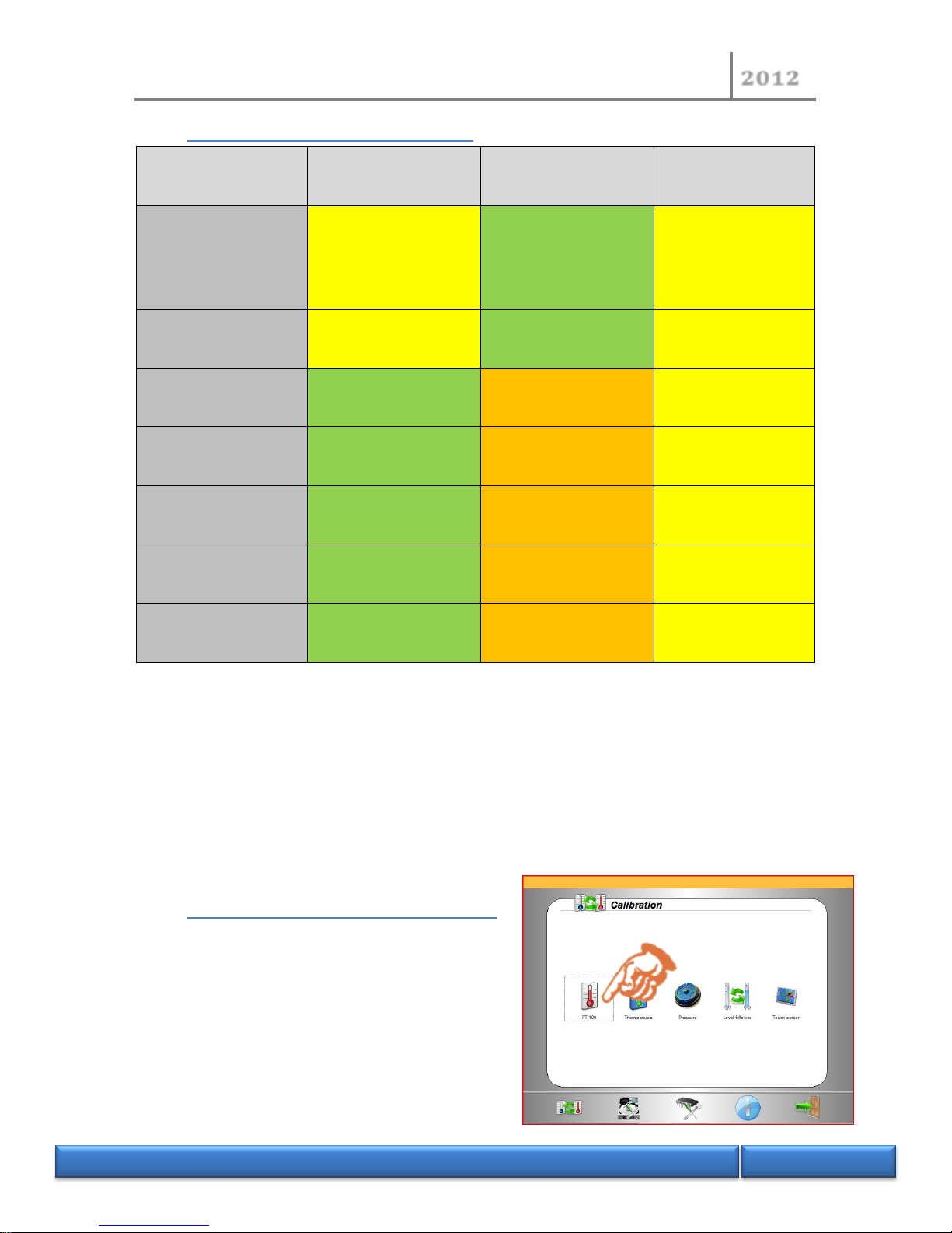
4.2 Options and equipment required
Sensor to be
calibrated
By
simulation
By
bath
By
point
Equipment necessary
Simulator + cable
reference XXX
Bath + extension lead
reference 60525 +
and the sensor to be
calibrated
Life book with
previous values
Sample probe
Possible
Cable ref 60522
Recommended
Possible
Condenser probe
Recommended
Cable ref 60524
Difficult to perform
Possible
Compartment probe
Recommended
Cable ref 60524
Difficult to perform
Possible
Ambient probe
Recommended
Cable ref 60524
Difficult to perform
Possible
TC dry point
Recommended
Cable ref 60523
Difficult to perform
Possible
TC Plate
Recommended
Cable ref 60523
Difficult to perform
Possible
The instrument does not allow storing in memory more than one calibration for fixed probes
(condenser, compartment and ambient probes).
For the sample probe, subject to much handling, it is possible to store as many calibrations as probes
are required. As a result with these previous calibrations, if the sample probe is defective or broken,
it is possible to connect another probe which has been previously calibrated and to select this
calibration to activate it.
4.3 Calibration of sample temperatures
Page 60
NORMALAB France
2012
N O R M A L A B F r a n c e
60/118
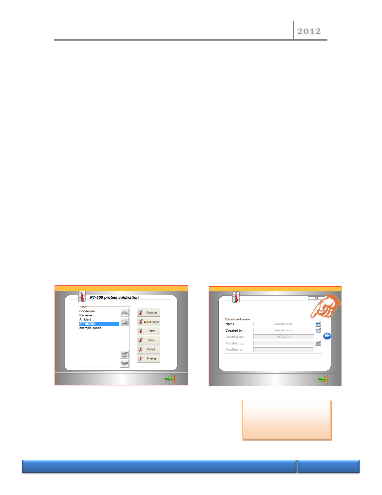
Enter the name of the probe
and identify the person
creating the calibration.
For each calibration, it is possible to:
- Creation: Create a new calibration (case of a new probe).
- Modification: Modify a calibration (in the event of a deviation or erroneous
measurements).
- Delete: Delete a calibration (if the probe is destroyed or calibration is false).
- Display: See a calibration (allows checking the points entered).
- Default: Declares a probe selected by default (this is the probe called up when starting a
test).
- Printing: Print out the calibration.
For sample probes, it is possible to store 1,000 calibrations. This allows carrying out a
calibration session when the measuring instruments are available and storing the calibrations
under the probe reference number. In operation, if it is necessary to change the probe
(following breakage or deviation in results), simply connect the new probe and declare it in
the instrument.
The display mode allows displaying the current calibration points and reading the value of
the temperature in real time.
4.3.1 Example of creation of a new calibration
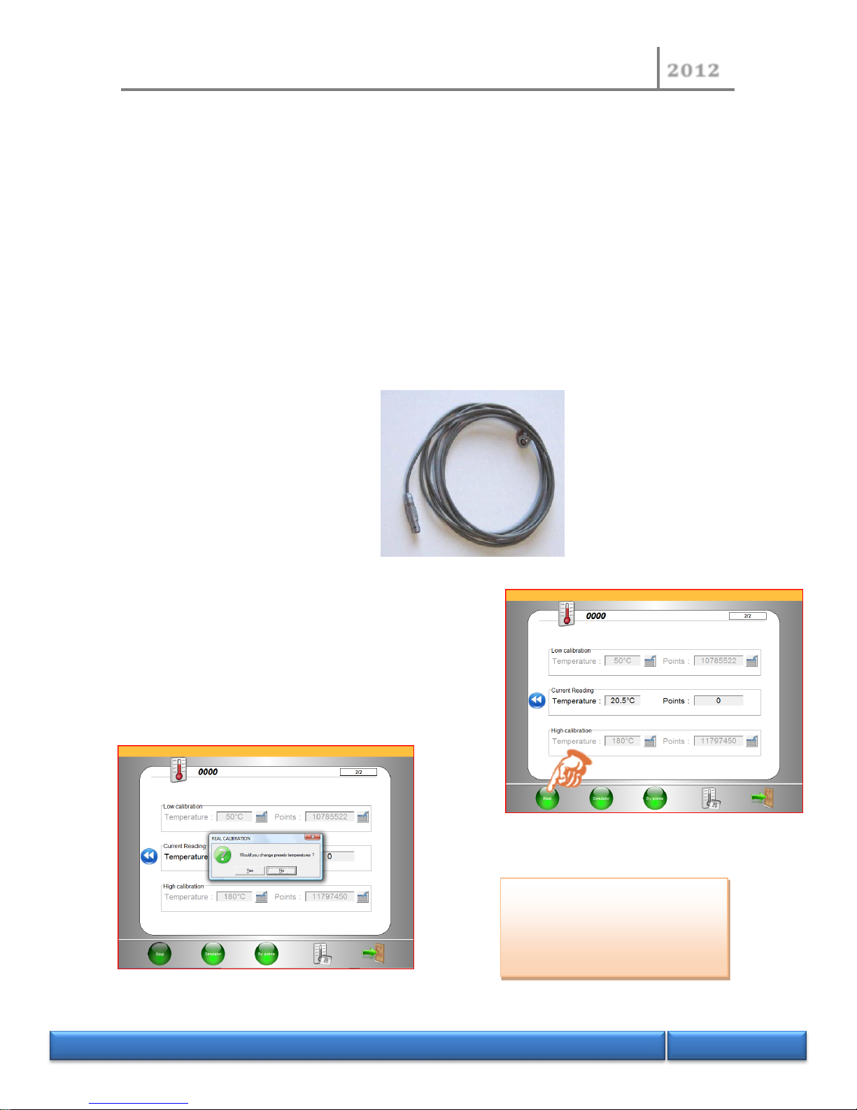
In the event of a modification, the previous
fields remain completed and the ‘modified by’
and the ‘modified on’ fields must be
completed before you can move on to the
next sequence.
Page 61
NORMALAB France
2012
N O R M A L A B F r a n c e
61/118
Respond yes or no depending on
the bath temperatures available
and values preselected on screen.
Depending on the equipment available, there are two possibilities:
- one or two baths stabilised at temperature are available and it is possible to carry out
calibration with the probe.
- One Pt100 probe simulator (decade resistor or calibrator): the probe will be replaced by
the simulator.
Calibration by bath:
- Disconnect the probe and insert the extension (accessory reference 60525) between the
probe and the instrument so the probe can be immersed in each calibration bath.
- Select the calibration mode (Real).
Page 62
NORMALAB France
2012
N O R M A L A B F r a n c e
62/118
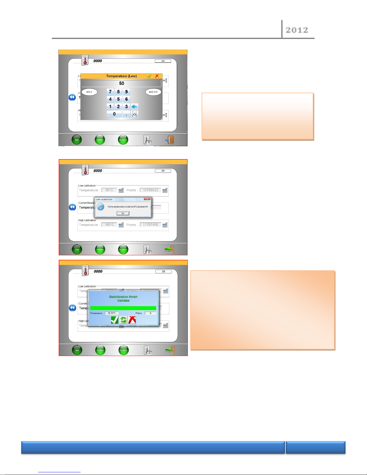
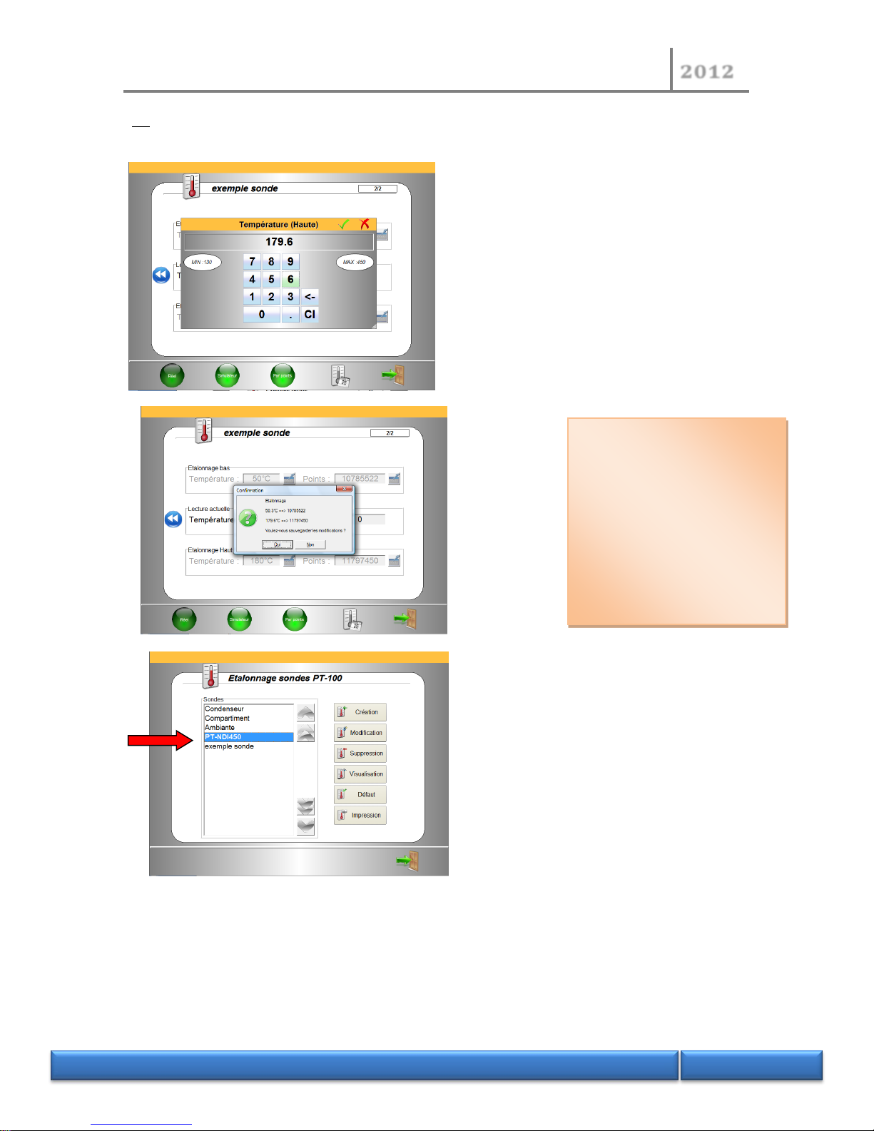
The instrument waits for the value read off to
stabilise (value stable at 800 conversion points) and
calculates the average of five acquisitions.
Confirm by selecting the green tick, restart
measuring by selecting ‘restart’ mode or cancel and
exit by selecting the red cross.
NB: to make a calibration with sufficient
accuracy, the system imposes a
difference of 80°C between the two
calibration points.
If preselections are not appropriate, reply ‘yes’
and use the keyboard on screen to enter the
new point values. End each input session with
a green tick.
The procedure requires placing the probe in
the lowest temperature bath (example
50.3°C) and confirming by ‘OK’.
Page 63
NORMALAB France
2012
N O R M A L A B F r a n c e
63/118
The procedure displays the calibration
points with the conversion points and
asks for confirmation or otherwise.
If confirmation is accepted, calibration
will be displayed and can be used when
selected by default.
NB: If the signal is too unstable, the instrument will not achieve stability and remains in this function.
It is possible to force it by pressing the green tick (but the calibration will not be accurate given the
instability).
Follow the same procedure for the high
calibration point, place the probe in the warmest
bath and confirm with the green tick.
Calibration with a simulator:
Calibration by simulation with a Pt 100 calibrator (or decade box) is similar to calibration by bath. It
requires the calibration cable reference 60522 to connect the calibrator in place of the probe.
This calibration allows calibrating the acquisition system of the instrument, excluding the
temperature probe. Error introduced by this sensor is not incorporated.
Page 64
NORMALAB France
2012
N O R M A L A B F r a n c e
64/118
4.3.2 Commissioning a new sample temperature probe
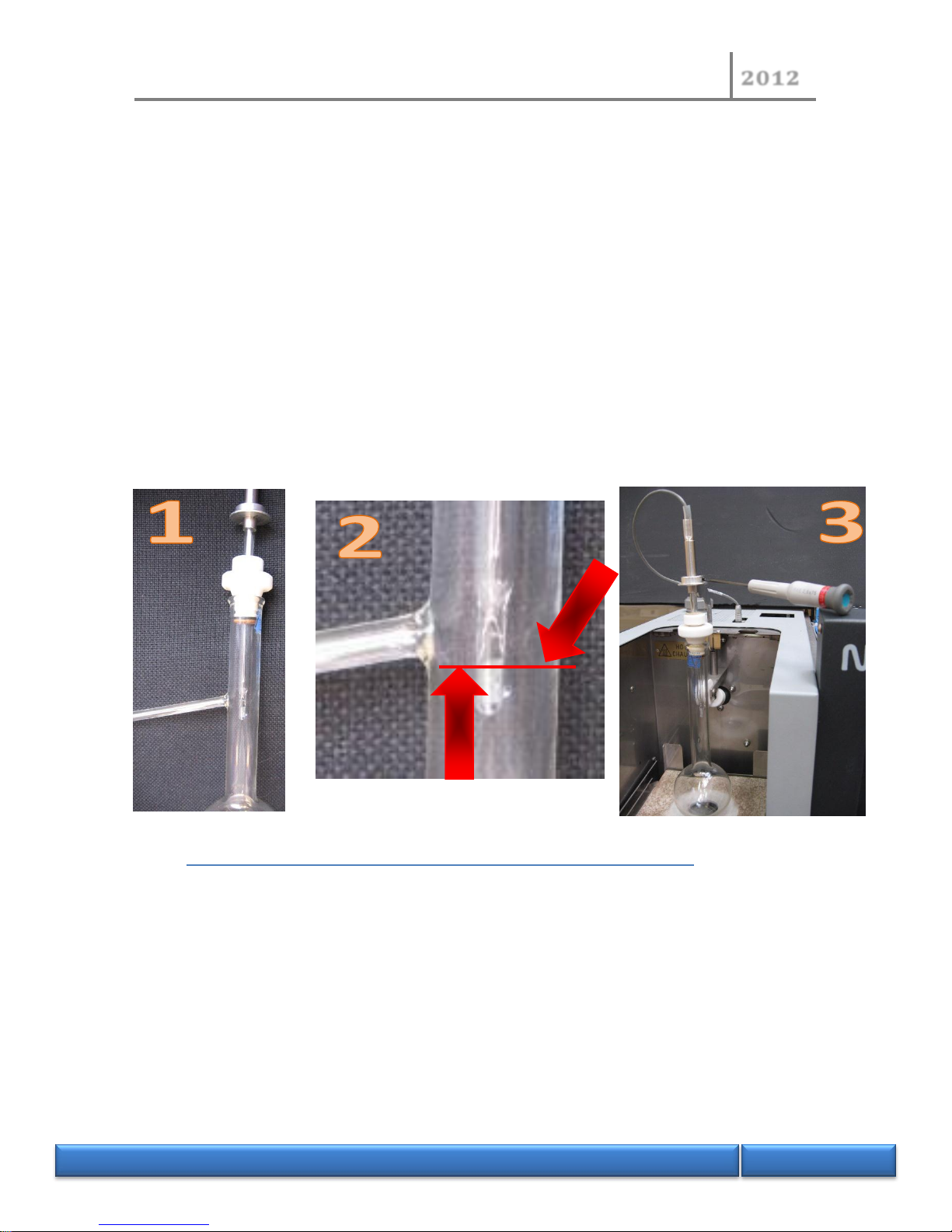
When commissioning a new sample temperature probe, it is necessary to verify the position of the
ring which detects correct positioning of the probe on the flask.
Place the centering stopper on the probe and place the whole assembly on the neck of the
flask (1).
Lower the probe to place the sensitive part of the probe perpendicular to the flask tapping
point (2).
Lock it in this position by turning the knurled ring of the centering stopper.
Place the flask with its centering stopper and its probe in the heating block and adjust height
of the probe ring so the detector is in the lower position when the assembly is in the final
position (centering stopper engaged in the flask neck). (3).
4.4 The Pt 100 temperature probes internal to the instrument
The condenser tube, test tube compartment and the ambient temperature probes fall into this
category.
It is not possible to create or delete a calibration for these probes.
The calibration procedure is identical to that for the sample probe (see above).
The probes are integral to the instrument, and calibration can be performed exclusively by
simulation.
NB: The error introduced by the sensor remains acceptable for these temperature measurements.
Page 65
NORMALAB France
2012
N O R M A L A B F r a n c e
65/118
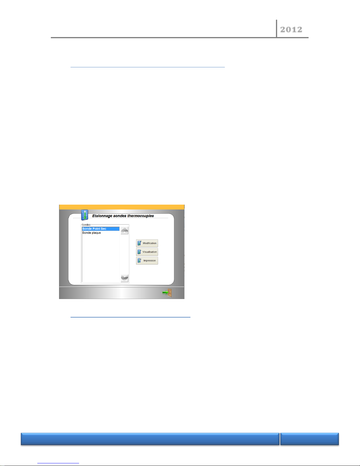
4.5 Temperature measurements by thermocouple
These measurements refer to:
- The dry point detection thermocouple
- The heating element temperature measuring thermocouple
The calibration of these sensors can only be performed in simulation mode using the calibration
reference 60523.
The sensor measuring temperature of the heating block is adjacent to the instrument. The
calibration procedure does not allow calibrating several heating block thermocouples
(referred to as the ‘plate probe’).
The procedure offers only modification or display of calibration of the Pt dry point
thermocouple since calibration of this element is not critical: the instrument uses the sensor
to detect the dry point by a temperature variation. The absolute temperature values are thus
not critical.
The procedure is identical to the Pt 100 probe
calibration by simulation (see above), simply
simulate two temperature points (a minimum
of 80 °C apart).
4.6 Calibration of the barometric sensor
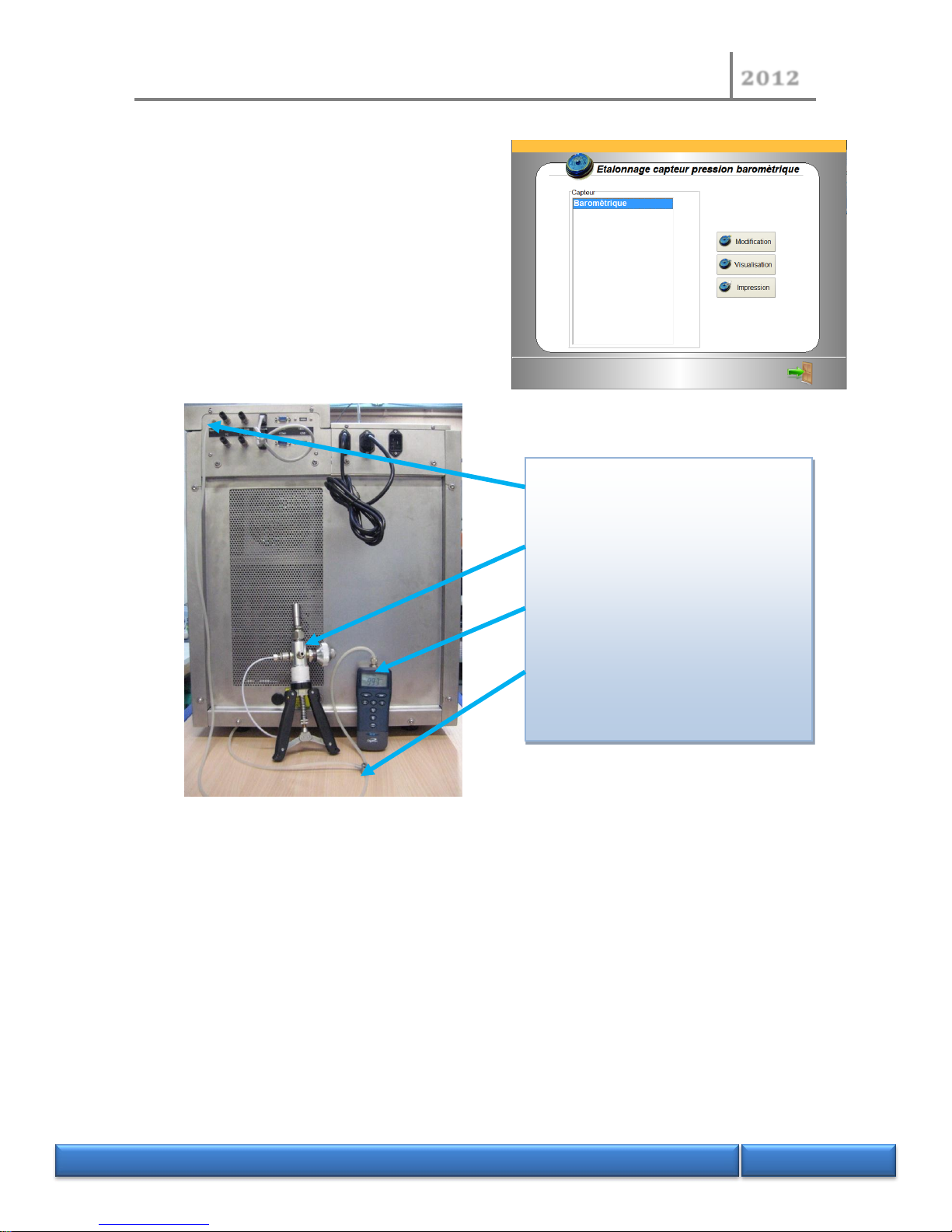
Barometric calibration allows modifying the calibration of the barometric sensor. Calibration is
performed by generating two atmospheric pressure values directly on the sensor.
Equipment required:
- One absolute standard reference pressure gauge
- One system allowing generating two pressures above and below atmospheric pressure
- One connection hose
Page 66
NORMALAB France
2012
N O R M A L A B F r a n c e
66/118
NB: If it is not possible to carry out
calibration of the barometric sensor
for lack of measuring equipment, it is
possible to set the instrument in
manual configuration to correct the
atmospheric pressure. As a result,
when starting the test, the
instrument will display a screen for
entering the barometric pressure
using the keyboard.
Display mode allows displaying the current calibration points and reading the atmospheric
pressure in real time.
When entering the calibration points, the instrument waits for stabilisation of the
measurement (variation below 0.3 mB) and calculates and average of five consecutive
acquisitions.
In order to perform a calibration which is sufficiently accurate, the two calibration points
must be a minimum of 100 mB apart.
Connection to internal barometric
pressure sensor
Pump generating different pressures
Absolute standard reference pressure
gauge used as the reference
T-junction connecting the sensor of the
instrument under calibration and the
absolute standard reference pressure
gauge to the pump.
Page 67
NORMALAB France
2012
N O R M A L A B F r a n c e
67/118
4.7 Calibration of test tubes
In order to measure the exact volume, calibration of test tubes used on the instrument is
recommended.
As for the sample temperature probes, it is possible to store several calibrations (maximum 1000).
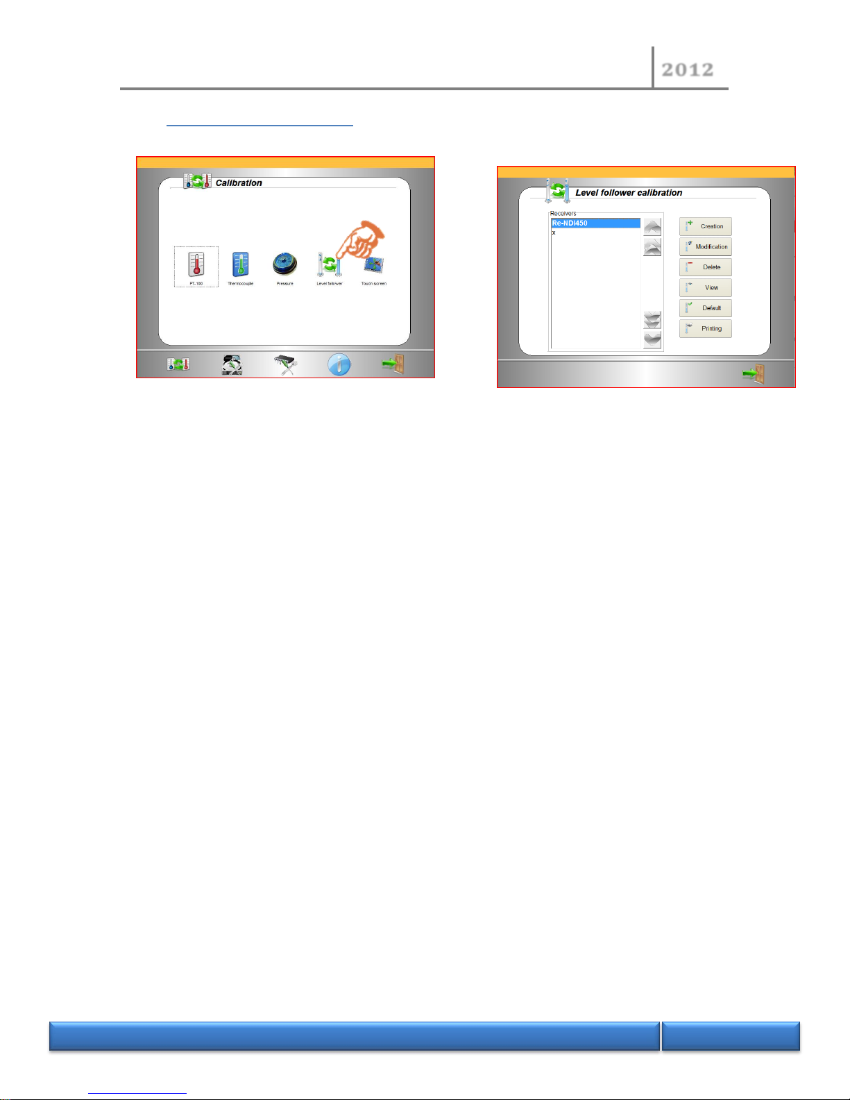
The level follower screen proposes:
- Creation: create a new calibration (case of a new test tube)
- Modification: modify a calibration (in the case of a deviation or erroneous
measurements)
- Deletion: delete a calibration (if the test tube is destroyed or the calibration is false)
- Display: display calibration (allows checking the points entered)
- Default: declares a test tube selected by default (it is this test tube that will be called up
when starting a test)
- Print: allows printing out the calibration values
The calibration procedure consists in placing two known precise volumes of liquid in the test tube.
During the procedure, it is possible to modify the two calibration volumes. However, in accordance
with the standard, it is recommended to retain the points 5 mL and 100 mL.
The 5mL point must be calculated precisely (by weighing or pipette). The 100 mL point will
preferably be made using the test tube graduation, since it is the mark that will be used
subsequently during the tests to pour 100 mL into the flask.
Page 68
NORMALAB France
2012
N O R M A L A B F r a n c e
68/118
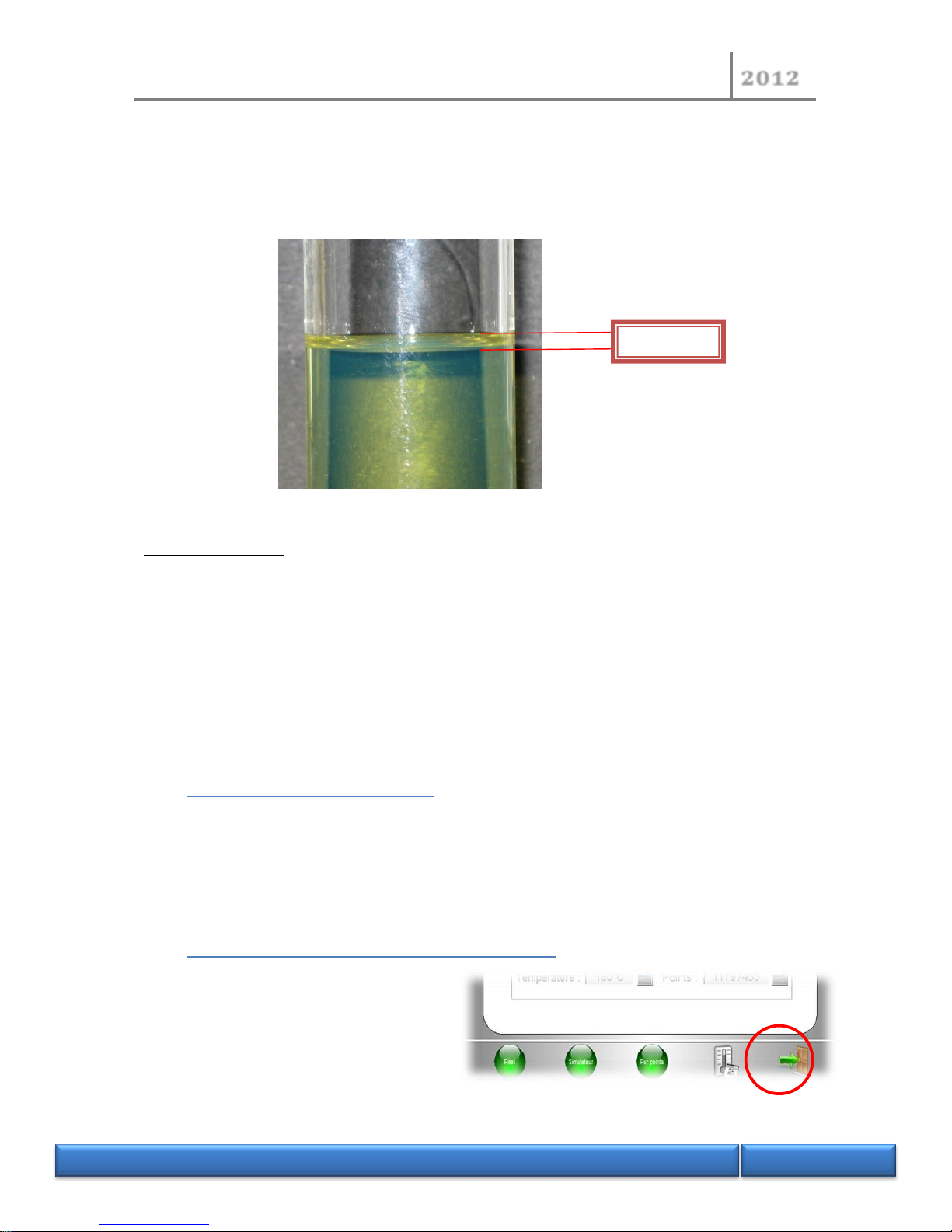
In order to ensure the same type of meniscus during calibration and measuring, it is
recommended carrying out calibration with the same type of liquid as the samples to be
analysed.
Procedure:
Equipment necessary:
- The test tube or test tubes to be calibrated.
- A 5 mL pipette or set of scales (range 200 G, accuracy 0.1 g and knowledge of exact
density).
- 120 mL of liquid similar to the samples.
Do not carry out calibration with water. The meniscus is contrary to that of
hydrocarbons.
Do not use extremely volatile liquids.
4.8 Calibration of the tactile pad
This function allows recalibrating the tactile pad with the screen. A utility is started and you are
requested to point at the points displayed on the screen.
4.9 Monitoring expiry of calibration deadlines
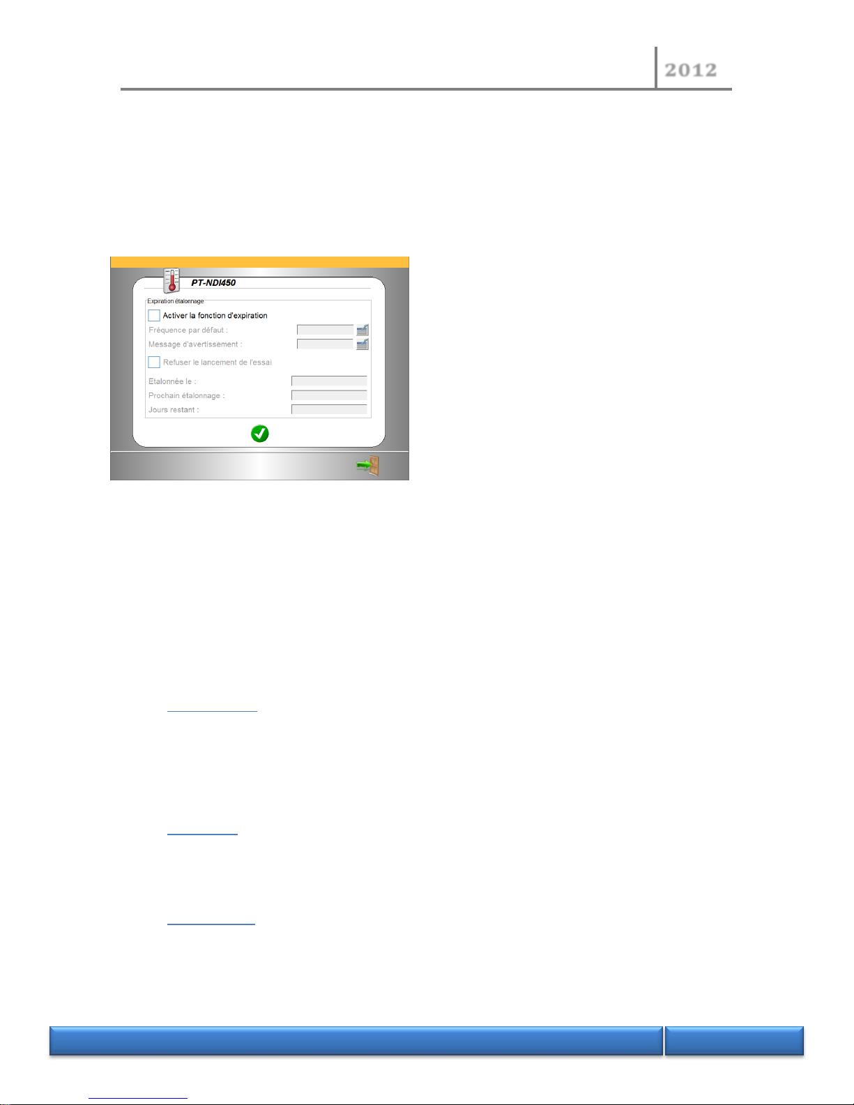
This function is not ticked on delivery of the
instrument.
Meniscus
Page 69
NORMALAB France
2012
N O R M A L A B F r a n c e
69/118
Its purpose is to monitor each magnitude to be calibrated in the instrument and expiry of the
calibration period.
It also allows, if the deadline is exceeded, prohibiting starting a test if the option is selected.
To choose this option, select the icon on each screen of a magnitude to be measured (after
completing the field “modified by” and the “modification” function).
If the expiry function is ticked, access is possible to
the frequency and warning message parameters:
Frequency: defines the frequency of validation of
calibration with as the starting point, the date of
calibration.
Warning message: an alarm message displayed X
days prior to expiry of calibration.
If the function “refuse to start test” is activated, it will not be possible to start a test with this
calibration.
5 Denomination and functions of the electronic boards
5.1 Process CPU
Manage acquisitions , regulations and processes
5.2 MMI CPU
Manage orders and peripherals : printer , displays , communication ports ( USB , Serial and Ethernet)
5.3 CL1 board :
- Manage the sensors :
o barometric pressure
Page 70

NORMALAB France
2012
N O R M A L A B F r a n c e
70/118
o PT 100 probes
o Thermocouples
o Drip deflector sensor
o Liquid detector of expansion tank
o Door sensor of heating block
o Door sensor of compartment
o Limit switches of level follower
o Optical sensor ( first drop and follower)
- Manage the I/O relay:
o General power supply
o Powering Peltier and stepper motor power supply
o Heating block relay
o Turbine of heating block
o Drive the stepper motor board
o Hot/cold compartment
o Hot/cold condenser
o Main circuit breaker tripping
o Check the main voltage
5.4 CL2 board :
Interconnection board
5.5 CL3 board :
Relay board :
- Main power
- Control for power Peltier, stepper motor and heating block transformer
- Relay circuit breaker tripping
5.6 CL4 board :
Interconnection board for Pt100 and thermocouple calibrations
5.7 CL56F et CL 56C boards :
Interconnection board :
- Between the process and MMi boards
- Between front panel and frame
Page 71

NORMALAB France
2012
N O R M A L A B F r a n c e
71/118
5.8 Stepper board:
Drive the stepper motor power
6 Schematic electrical and electronic
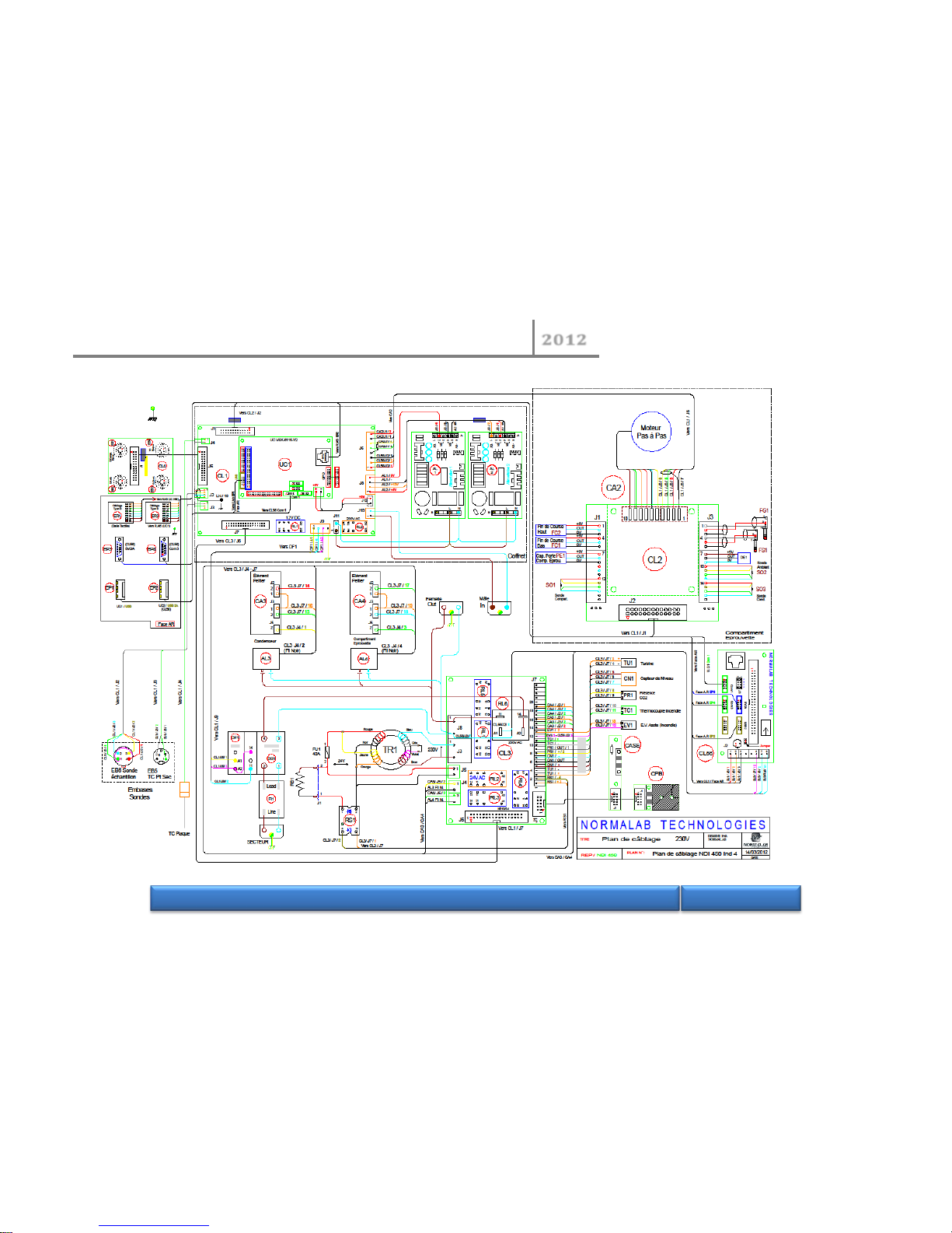
6.1 Interconnection scheme
Page 72
NORMALAB France
2012
N O R M A L A B F r a n c e
72/118
Page 73
NORMALAB France
2012
N O R M A L A B F r a n c e
73/118
6.2 Spares part list
6.2.1 Probes and thermocouples
6.2.2 First drop and follower optical sensors
Page 74
NORMALAB France
2012
N O R M A L A B F r a n c e
74/118
6.3 Scheme of electronic boards
6.3.1 CL1 board
Page 75
NORMALAB France
2012
N O R M A L A B F r a n c e
75/118
Page 76
NORMALAB France
2012
N O R M A L A B F r a n c e
76/118
6.3.2 CL2 board
Page 77
NORMALAB France
2012
N O R M A L A B F r a n c e
77/118
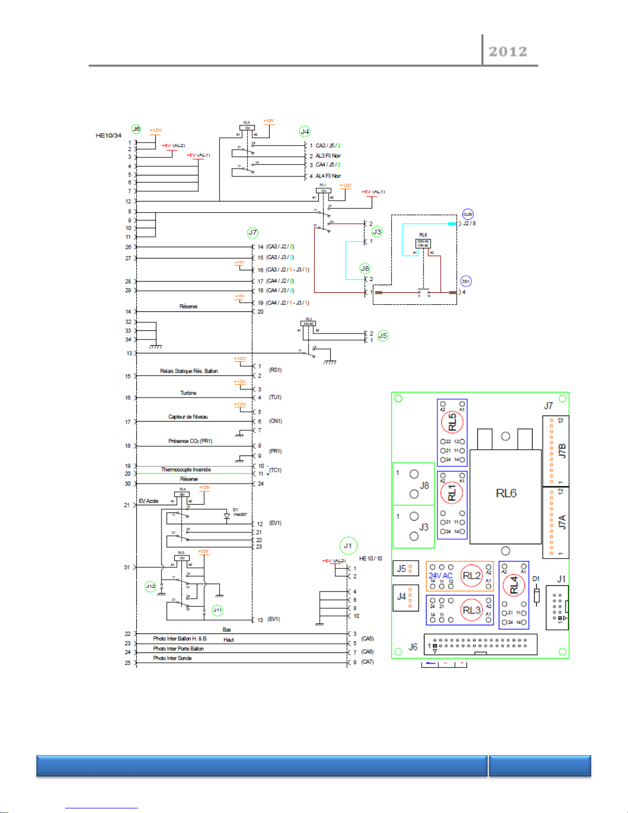
6.3.3 CL3 Board
Page 78
NORMALAB France
2012
N O R M A L A B F r a n c e
78/118
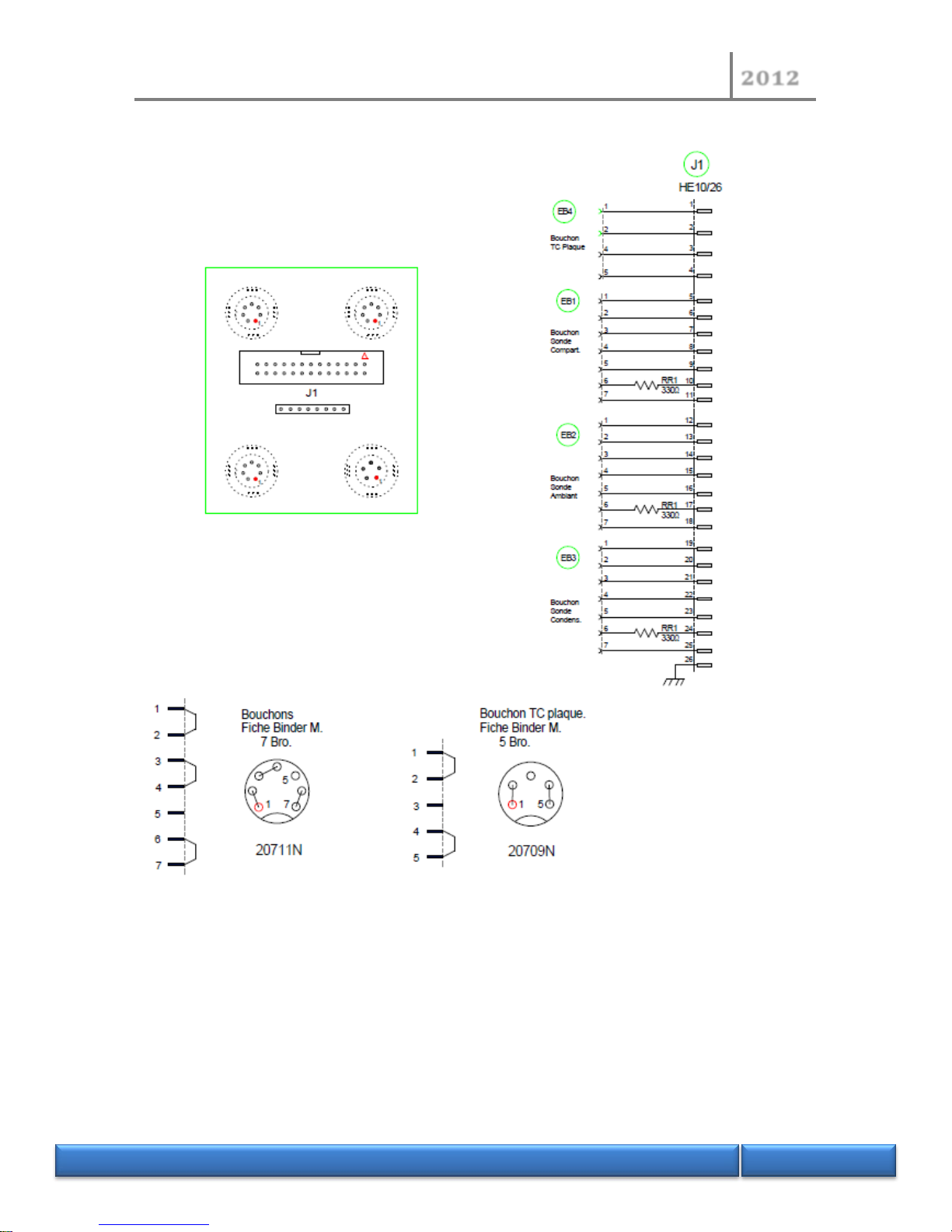
6.3.4 CL4 board
Page 79
NORMALAB France
2012
N O R M A L A B F r a n c e
79/118
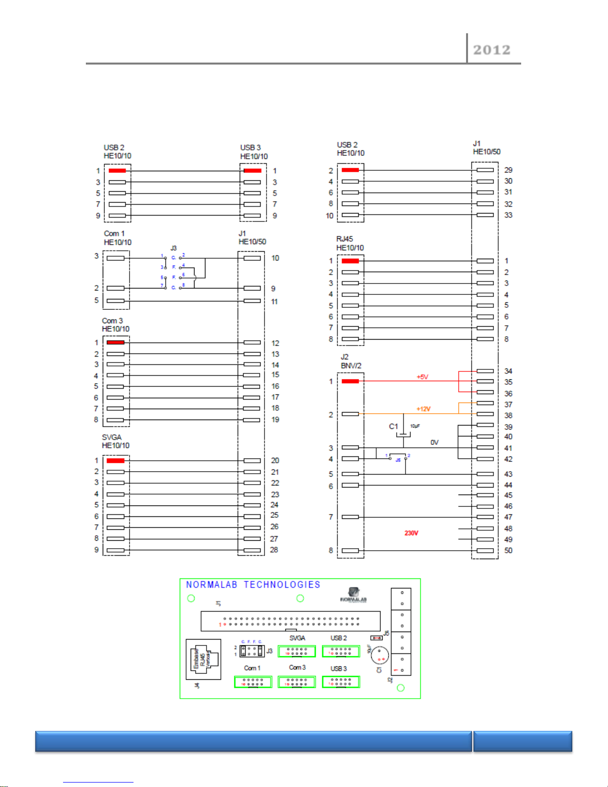
6.3.5 CL56 board
Page 80
NORMALAB France
2012
N O R M A L A B F r a n c e
80/118
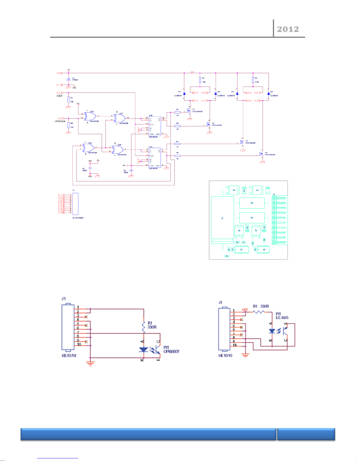
6.3.6 Stepper motor board
6.3.7 Detector probe and door closed detector sensor
Page 81
NORMALAB France
2012
N O R M A L A B F r a n c e
81/118
6.3.8 Front panel
Page 82
NORMALAB France
2012
N O R M A L A B F r a n c e
82/118
Page 83
NORMALAB France
2012
N O R M A L A B F r a n c e
83/118
7 Spares part list
26111
100 mL glass test tube with base
60516
100 mL anti-mist glass test tube with base
60512
Diaphragm
60514
Bag of pumice stone
60513
Condenser cleaning cable
12609EC
5mL graduated cylinder for residue
40065
Centering stopper for 125 mL flask
40064
Centering stopper for 125 mL flask with
passage for dry point thermocouple (for dry
point in D86)
40067
Centering stopper for 200 mL flask
Page 84
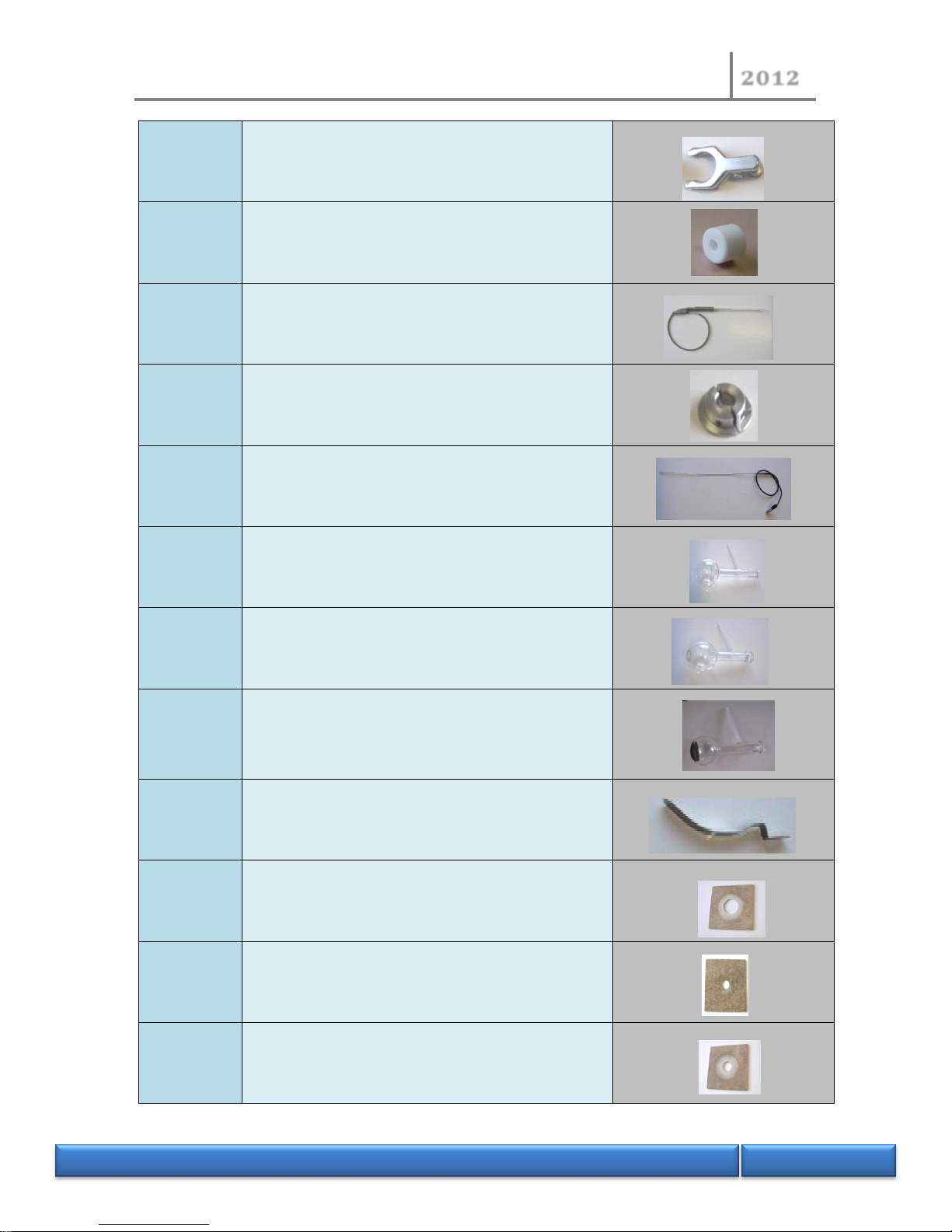
NORMALAB France
2012
N O R M A L A B F r a n c e
84/118
40081
Grip for centering plug for 200 mL flask
60515
Stopper for connecting condenser tube and
flask
60510
PT 100 sample probe without position ring
60552
Position ring for Pt 100 sample probe
60509
Thermocouple for dry point detection
24019
125 mL flask
19422
200 mL flask
40043
200 mL flask with black base
60511
Drip deflector(packet of 5 parts)
60508
Heating block plate with hole diameter 50 mm
60507
Heating block plate with hole diameter 38 mm
60506
Heating block plate with hole diameter 32 mm
Page 85
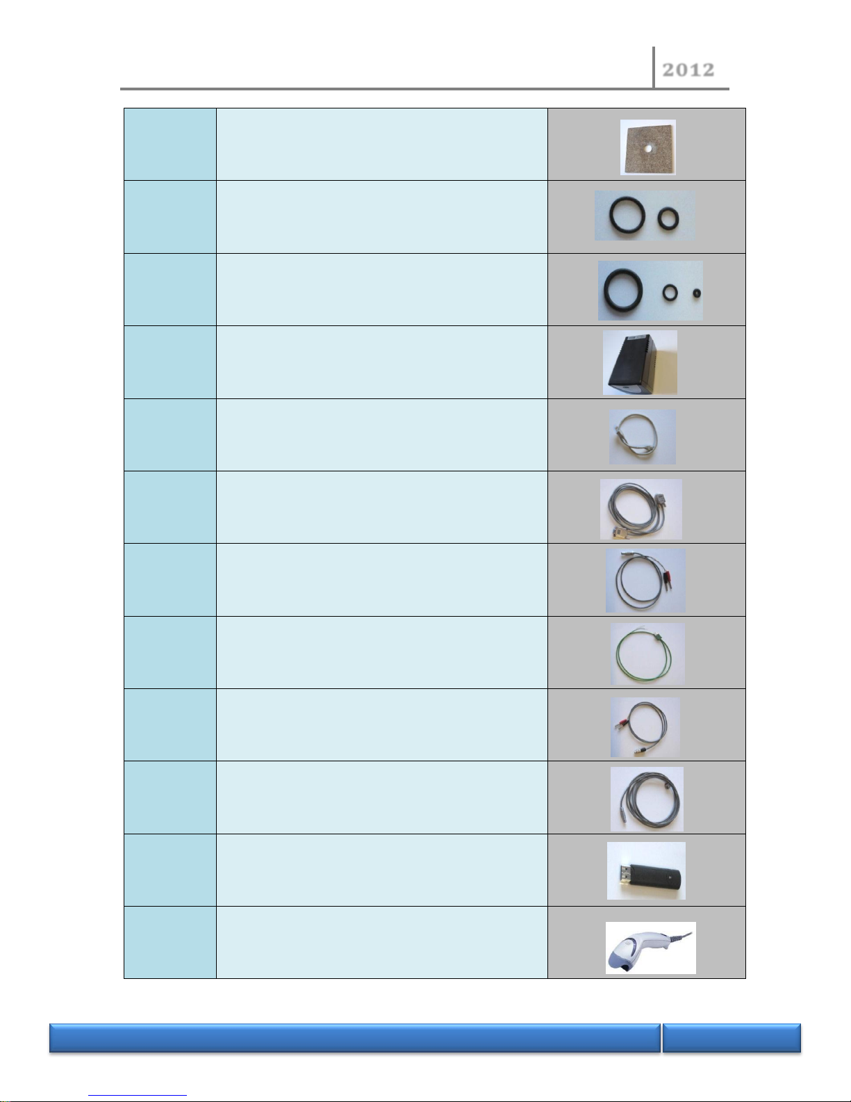
NORMALAB France
2012
N O R M A L A B F r a n c e
85/118
60505
Heating block plate with hole diameter 25 mm
40040
Kit of 10x 'O' ring seals with centering stopper
for 125 mL flask
40042
Kit of 10 'O' ring seals with centering stopper
for 200 mL
60520
Uninterruptible power supply (UPS)
60521
Ethernet Cable
60532
Serial Cable (RS232)
60522
Sample temperature measuring calibration
cable by simulation
60523
Calibration cable for measuring thermocouple
temperature by simulation
60524
Calibration cable for measuring internal Pt
100 probe by simulation
60525
Extension cable for calibrating the sample
temperature measuring system using a bath
60526
USB key with retrieval system
60527
Bar code reader
Page 86
NORMALAB France
2012
N O R M A L A B F r a n c e
86/118
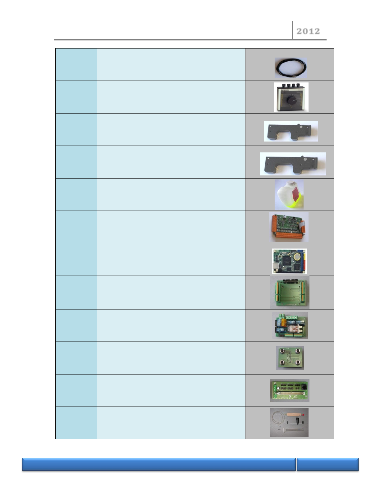
60528
Extinguishing system nitrogen connection
tube
60553
Resistor box to simulate Pt100 probes
60554
1st drop detection fork
60555
Level follower fork
40012
Coolant liquid (2 liter bottle)
60556
CL1interface card
60557
UC IHM card
60546
CL2 card
60547
CL3 card
60548
CL4 card
60549
CL56 card
60558
Kit VOC ( zeolite)
Page 87
NORMALAB France
2012
N O R M A L A B F r a n c e
87/118
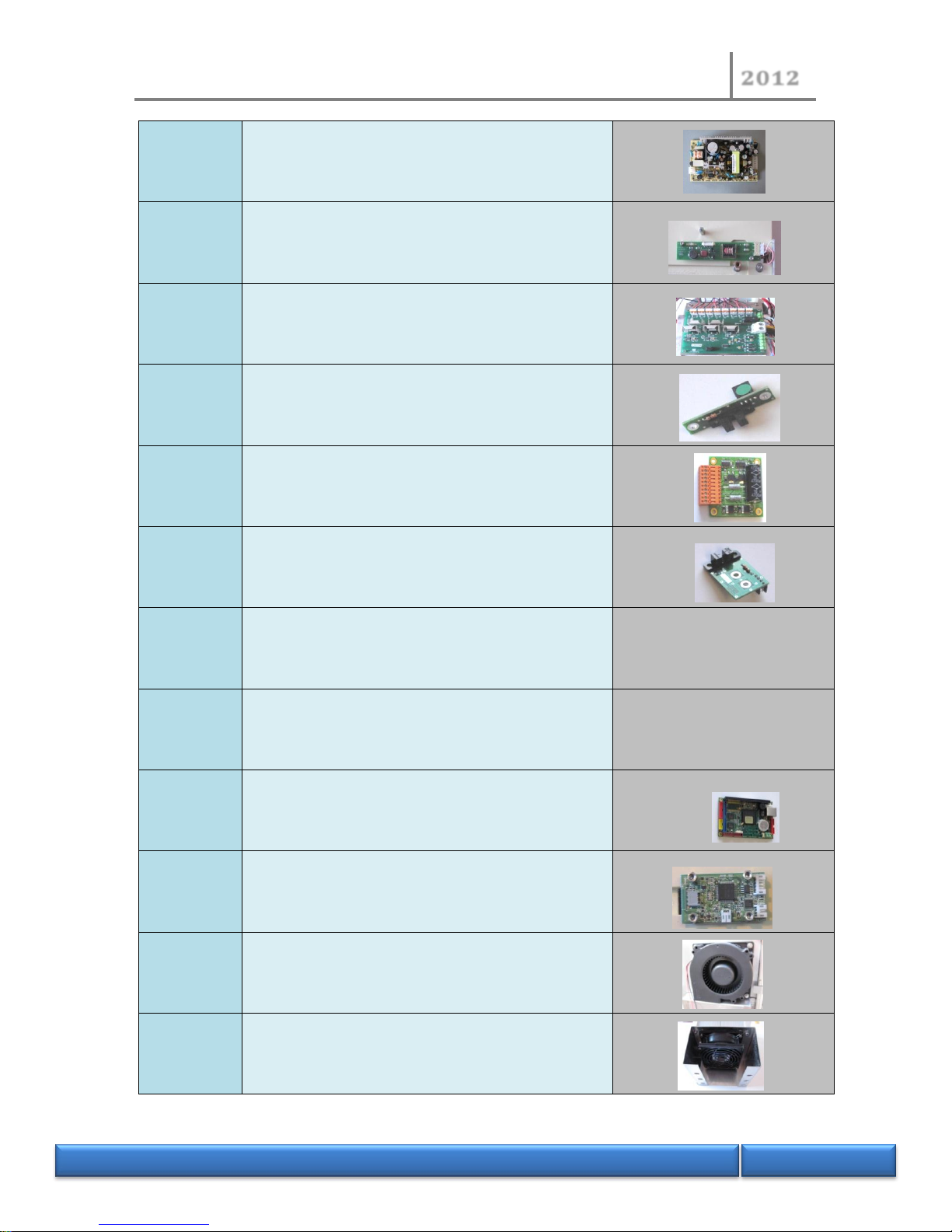
60559
Electronic cards power supply
60560
Back-light card
60561
Peltier element S/E regulation control card
(compartment or condenser)
60562
Sample probe presence sensor card
60563
Step motor card
60564
Heating block high position sensor card
60550
230 V color inkjet printer
None
60551
115 V color inkjet printer
None
60565
Process CPU
60566
Touch pad driver
60567
flask heating block cooling turbine
60568
Condenser Peltier S/A fan (without filter)
Page 88
NORMALAB France
2012
N O R M A L A B F r a n c e
88/118
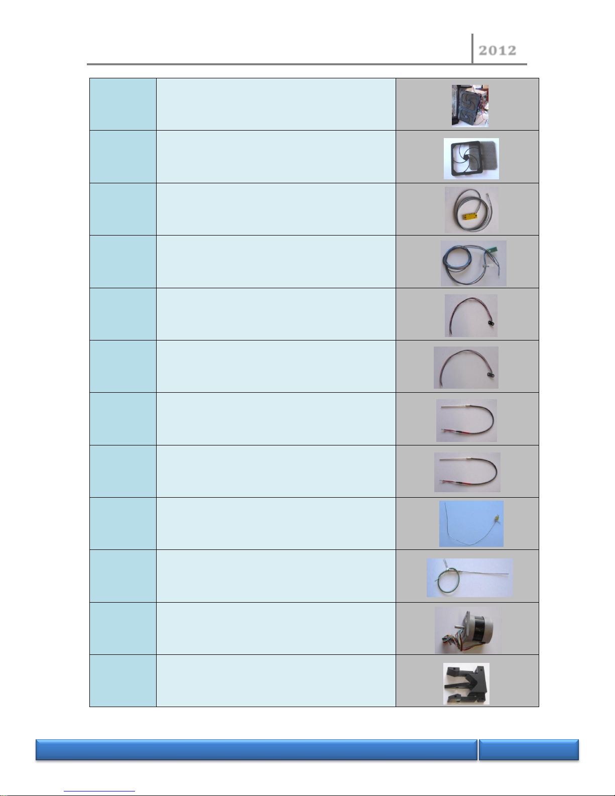
60569
Compartment Peltier S/A fan (without filters)
60570
Dust filter for fan Peltier S/A
60571
Sensor detection of level in fluid circuit coolant
liquid
60572
Drip deflector detection sensor
60573
Compartment door closed detection sensor
60574
Sensor detecting follower high or low position
60575
Pt 100 probe - condenser temperature
60576
PT 100 probe - test tube compartment
temperature
60577
flask heating block thermocouple
60578
Heating block detection thermocouple
60579
Level follower step motor
60580
Low test tube retention system
Page 89
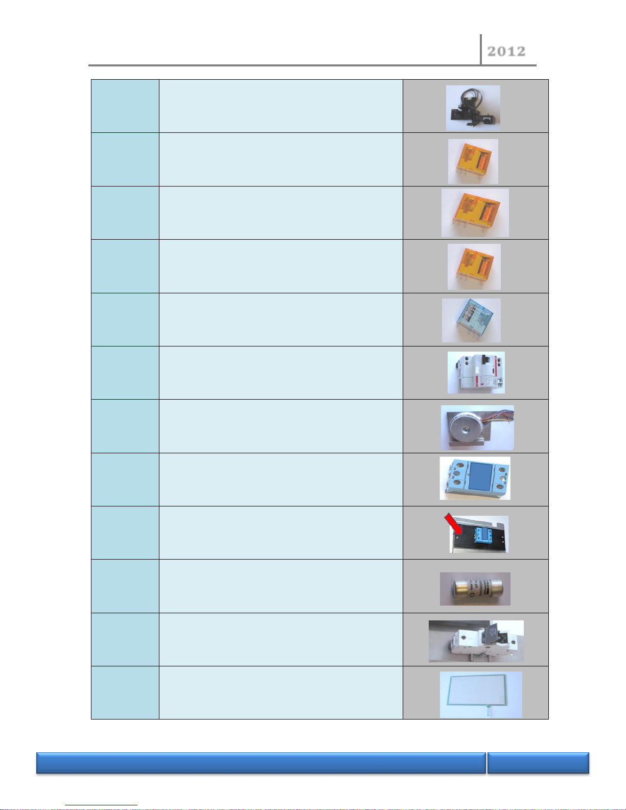
NORMALAB France
2012
N O R M A L A B F r a n c e
89/118
60581
High test tube retention system with detection
of flow finger
60582
12 V DC relay
60583
230 V AC relay
60584
24 V DC relay
60585
125 V AC relay
60586
Main circuit breaker
60587
800 VA 25 V transformer
60588
Heating block heating static relay
60589
Static relay heat sink
60590
Heating circuit fuse 40A 14X51 mm (box of 10
fuses)
60591
Fuse holder for heating block heating circuit
60592
Touch pad
Page 90
NORMALAB France
2012
N O R M A L A B F r a n c e
90/118
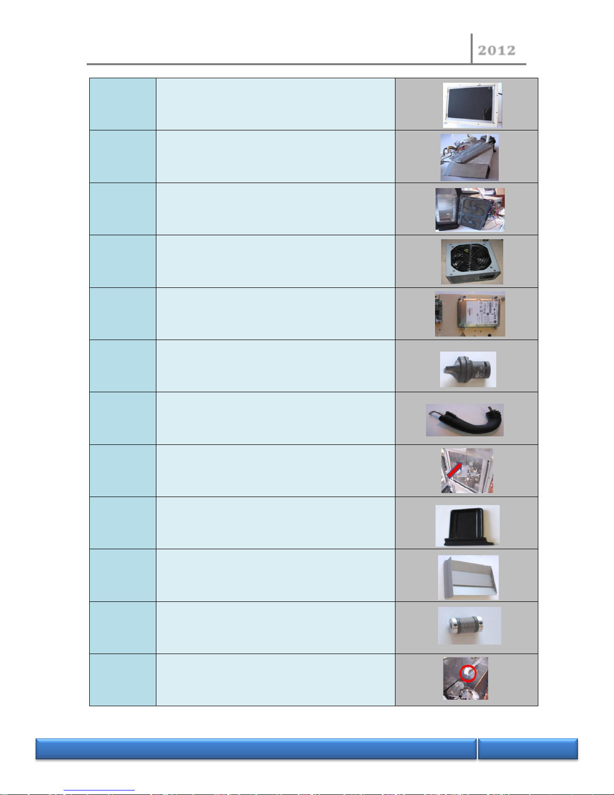
60593
LCD color screen
60594
Condenser temperature regulation subassembly
60595
Test tube compartment temperature
regulation sub-assembly
60596
Peltier element S/A power supply
(compartment or condenser)
60597
Hard disk with Windows license
60598
Mains on/off switch
60599
Insulated full condenser tube assembly
60600
Glass door of heating bloc
60601
Condensate drawer compartment
60602
Collection drawer of heating block
60603
Coupling for step motor
60604
Centering roller for flask in heating block
Page 91
NORMALAB France
2012
N O R M A L A B F r a n c e
91/118
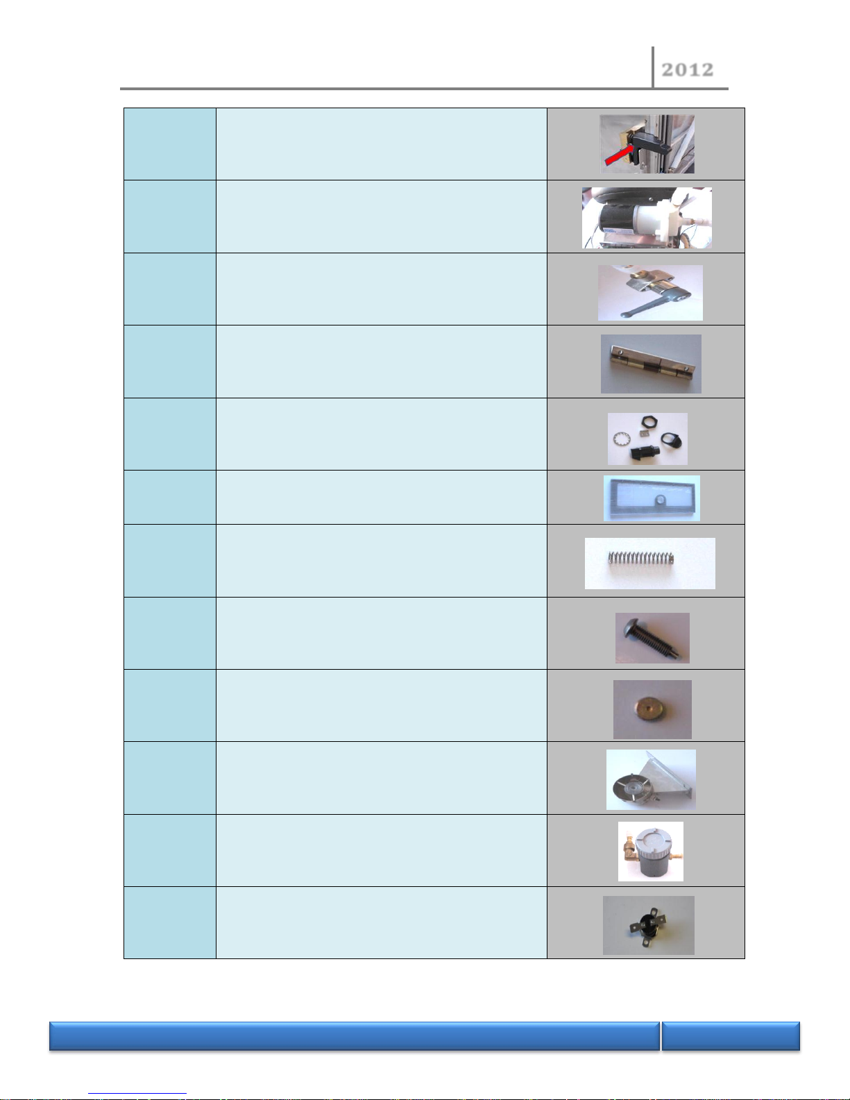
60605
Latch for locking heating block door
60606
Circulation pump for coolant circuit
60607
Coolant circuit drain valve
60608
Receiver compartment door hinge with spring
(pair)
60609
Latch for locking test tube compartment door
60610
Receiver compartment door
60611
1st drip fork or follower spring
60612
Magnet for follower position detect
60613
Magnet for test tube compartment door
60540
flask heating element sub-assembly with
thermocouple
60615
Fluid circuit expansion chamber
60616
Head sink thermostat
Page 92
NORMALAB France
2012
N O R M A L A B F r a n c e
92/118
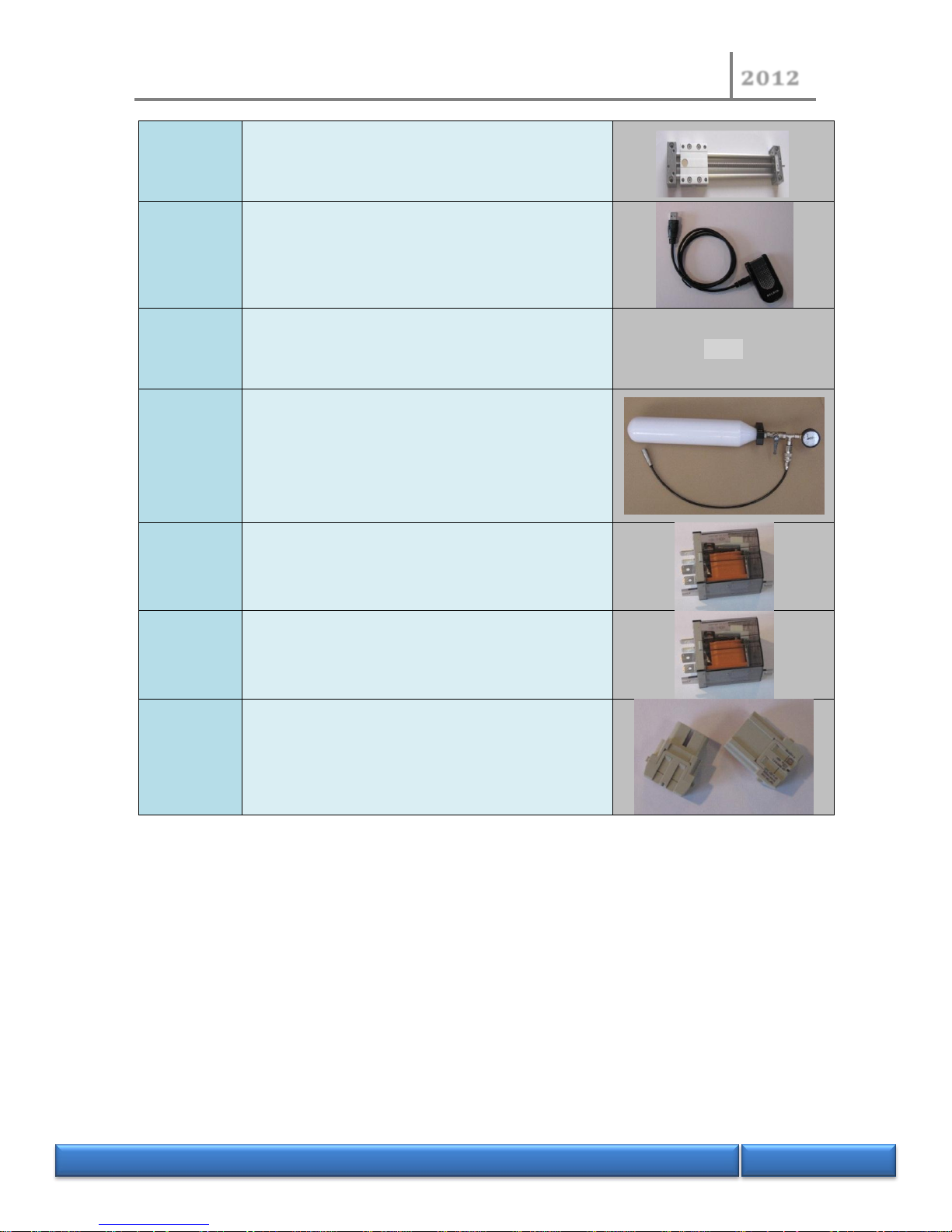
60617
Translator for test tube compartment follower
60529
4 port 2.0 USB hub
60530
Nitrogen electro valve kit for test tube
compartment
none
60531
Extinguishing system nitrogen bottle
60618
30 A 230 V power relay
60619
30 A 115 V power relay
60620
Set of 2 power switches contacts (male and
female) for heating block heating element
Page 93
NORMALAB France
2012
N O R M A L A B F r a n c e
93/118
8 Troubles shooting
Degraded
function
Description
Solution or check to perform
General
The circuit breaker does
not remain engaged.
Verify that the mains voltage is in
concordance with that displayed on the
instrument.
The circuit breaker is
tripped when a test is
started.
Check that the transformer of the flask
heating circuit.
Switchover the switch on the two internal
power supplies and verify whether the
problem persists.
The fuse of the heating
block heating element
has blown.
Verify that the heating element circuit is not
damaged.
Problems on
results
The results are
divergent in
temperature
Verify that the sample temperature probe is
correctly displayed and calibrated.
Verify that calibration of the test tube and its
declaration.
Verify that calibration of the barometric
sensor.
Verify that the final volume.
Verify that leak tightness of the stopper
connection between the flask and condenser
tube.
Initial boiling point is
divergent
Verify that temperature conditioning of the
sample on starting the test.
Verify that the position of the probe in the
flask neck (see standard).
The test does not
Problem of adjustment
Verify that the power leads for the internal
Page 94
NORMALAB France
2012
N O R M A L A B F r a n c e
94/118
start or takes a
long time to start
of compartment or
condenser temperature
power supplies are correctly positioned.
Verify that the switch for each internal
power supply is at ‘on’.
Verify that the fan filters are not clogged by
dust.
Verify that the temperature exchanges of
the compartment or condenser subassemblies are not clogged by dust.
Verify that the fans can rotate freely.
Verify the ambient temperature in the
laboratory and of the instrument (proximity
to an instrument emitting hot air).
Verify the level of liquid in the expansion
chamber of the condenser circuit.
Verify that the condenser circuit circulation
pump is operating.
The heating element of
the heating block does
not heat up, or heats up
only slightly
Verify the heating circuit fuse.
Verify the heating thresholds in the product
file.
Verify the calibration of the heating block
thermocouple.
Flow rate
incorrect or
unstable
Poor regulation of flow
rate
Check that the drip deflector is correctly
positioned (it must touch the glass wall on
the front).
Place glass balls or pumice stone in the flask
to attenuate disturbance during boiling.
Verify the values in the product file.
Verify that the sample does not swell up
because of a not adapted product file or
presence of water in the sample.
Verify that the instrument is stable and
Page 95
NORMALAB France
2012
N O R M A L A B F r a n c e
95/118
exempt from vibration (which can generate
surface waves on the liquid and interfere
with the follower).
Verify the calibration of the plate
thermocouple.
Verify the mechanical position of the plate
thermocouple.
Flow rate value not
correct.
Product file ill-adapted.
Poor choice of standard.
Heating block plate ill-adapted.
Level follower
The follower rises
without any liquid in the
test tube
Check the for presence of mist on test tube.
Check the cleanliness of test tube and optical
sensor (emitter and receiver).
The follower does not
follow the liquid.
Verify the positioning of the follower cell in
relation to the test tube.
Detection of initial
point (IBP)
The instrument does
not detect the initial
point (IBP)
Verify alignment of the cell with the
perpendicular of the end of the condenser
tube.
Verify absence of mist or other particles
perpendicular to the optical detector.
Poor initial boiling point
value (IBP)
The condenser was not cleaned before the
test.
Condenser temperature ill-adapted for
sample (risk of fixing in the condenser).
Dry Point
Detection
No detection or
divergent value
Verify the sensitivity displayed.
Verify the dry point was requested in the
product file.
Verify the dry point actually exists (too much
residue).
Page 96

NORMALAB France
2012
N O R M A L A B F r a n c e
96/118
Final boiling point
detection (FBP)
No detection or
divergent value
Verify that the modification of final heating
is not too great in relation to the declared
detection threshold.
Verify declared protection threshold.
Final volume
The final volume is not
correct
Verify the calibration of the test tube and its
declaration.
Ensure that the initial volume was correct.
Verify that the temperature of the test tube
compartment is correct (an increase in the
temperature expands the liquid and falsifies
measurement of the volume or evaporates
light distillate samples).
Verify the final residue.
Verify the leak tightness of the connection
stopper between the flask and silicone tube.
Verify the presence and efficacy of the
diaphragm on the test tube neck (case of
light distillate products).
The test tube has been cleaned and dried
before charging in the flask (error on drips
remaining in the test tube).
Poor calibration with a liquid generating a
convex meniscus (verify with level detector
on the sample).
Page 97

NORMALAB France
2012
N O R M A L A B F r a n c e
97/118
9 Annexe 1
9.1 Guide to update instrument
9.2 Safety rules
NORMALAB NDI 450 distillation unit is a high quality instrument. The recommendations and
instructions in this document will allow you to update your instrument. Make sure you read and
understand this guide. Keep it close to the instrument so you can consult it easily.
9.3 General characteristics
The distillation unit is offering two microprocessor cards. One computer board under Windows XP
Embedded operating system for Man Machine Interaction (MMI software). And other computer
board under Free-Dos operating system for instrument process (For convenience, we call this
software "firmware"). To ensure this equipment provides the reliable prolonged service for which it
was designed, we emphasize the importance of updating or upgrading the MMI software and the
firmware on regular bases.
9.4 Content of new version
A new version includes adjustments, new improvements to features and services in NDI450 software.
This update replaces your current version of NDI450 software, and keeps your files and settings in
place in your instrument. You can check the new adjustments and features here:
http://www.normalab.com/software/NDI450/NDI450 What's new.pdf
9.5 How to get a new version
The recommended (and easiest) way to get NDI450 new software is to download on Normalab
Website. Download and save the appropriate files for your instrument from the Normalab NDI450
Download Center: http://www.normalab.com/software/NDI450/Software/Update.zip
Page 98
NORMALAB France
2012
N O R M A L A B F r a n c e
98/118
9.6 How to know the software version
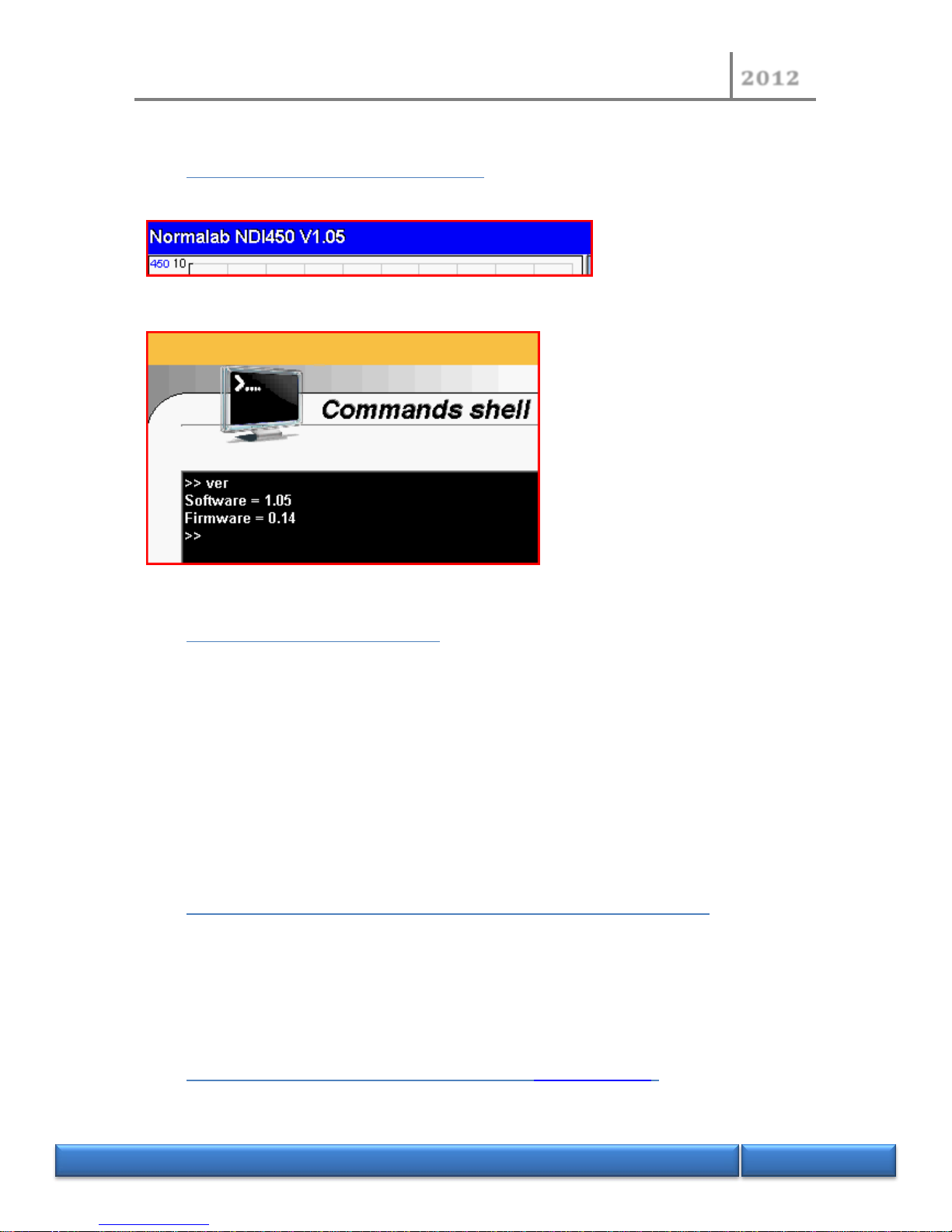
The MMI ID software version is visible in the toolbar on the main screen.
The firmware version is visible in the “Command shell“page with the command “ver”.
9.7 Important recommendations
- Make a new backup of MMI software before starting an update.
- Please always check the software or firmware version before starting an update.
- Never update your instrument with a previous version than the installed one.
- Be sure your new version is compatible with your instrument. Please contact us for
confirmation.
An incorrect installation can involve a dysfunction of the unit, company NORMALAB France SAS
could not be responsible for incorrect installation of software or firmware done by your side on
this equipment.
9.8 Additional requirements to update your NDI450 instrument
- 1 Computer with Internet access (fees may apply).
- 1 USB flash/pen/key/stick drive (Don’t use the USB flash drive supplied with your
instrument).
- 1 Ethernet cable for update the firmware (It’s supplied with your instrument).
9.9 Prepare your USB flash drive for updating (video example)
- Plug-in the USB flash drive to computer
Page 99
NORMALAB France
2012
N O R M A L A B F r a n c e
99/118
- Open the drive letter assigned to the USB flash drive by looking at the list of drives in window
explorer.
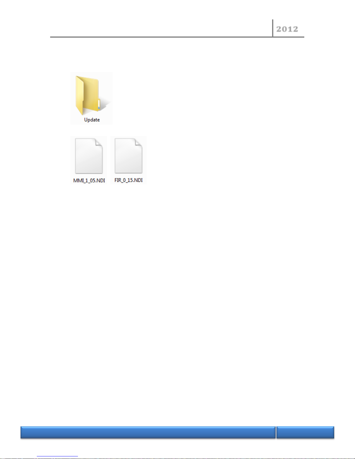
- Create a new folder named “Update” (if not exist).
- Extract and copy the NDI450 new version into the Update folder.
The file named “MMI_X_XX.NDI” is the update version for the MMI software. The version number of
the new software is “X_XX”.
The file named “FIR_Y_YY.NDI” is the update version for the firmware. The version number of the new
firmware is “Y_YY”.
- Unplug the USB flash drive from the computer.
Page 100
NORMALAB France
2012
N O R M A L A B F r a n c e
100/118
9.10 Install a new MMI version using the Update option (video example)
- After NDI450 software has started, check the version of the MMI software before starting an
update.
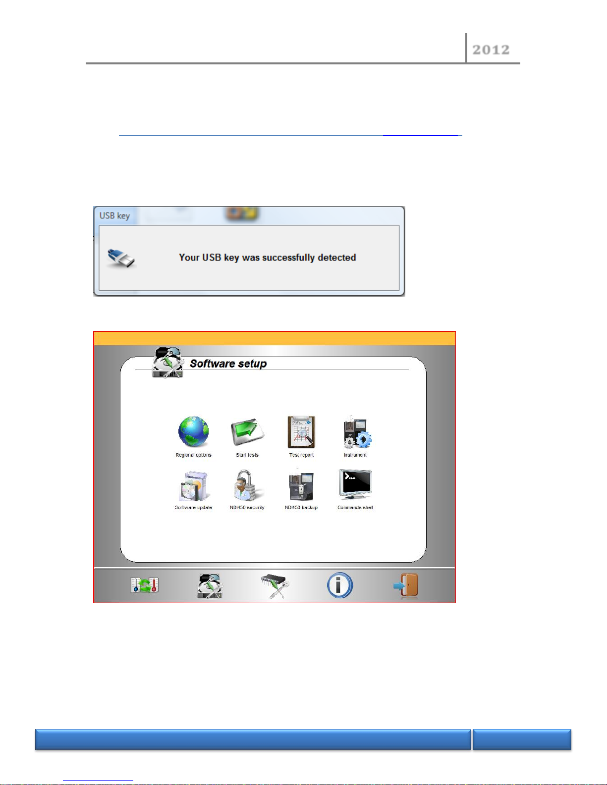
- Plug-in the USB flash drive to your instrument. Software should detect automatically your
USB flash drive.
- On the “Software setup” page, click “Software update”.
- On the “Software update” page, click “Load the updates list”.
 Loading...