

Page 1

LARGE CAPACITY INCUBATOR
Installation, Operation and
Maintenance Instructions
GENERAL
Inspection 2 Location 2
INSTALLATION
Door Alignment 2 Shelf Installation 2 Remote Contacts 2 2-10 Volt DC Output 2 RS485 Port 3 Internal Outlet 3 Access Port 3
Glycerin Well Assembly 3
OPERATION Drawer Option 4
MAINTENANCE
Periodic Cleaning 5 Maintenance Service and
Analysis Guide
2
2
3
5
6
1 7/10 Rev. C 131783
Page 2
GENERAL
INSPECTION
When the equipment is received, all items should be carefully checked against the bill of lading to
insure all crates and cartons have been received. All units should be inspected for concealed
damage by uncrating the units immediately. If any damage is found, it should be reported to the
carrier at once, and a claim should be filed with the carrier. This equipment has been inspected and
tested in the manufacturing facility and has been crated in accordance with transportation rules and
guidelines. Manufacturer is not responsible for freight loss or damage.
LOCATION
The cabinet should also be leveled when it is placed in its permanent location. Do not stack items
on top of the unit. Vibration during shipping and handling may loosen mechanical connections.
Check all connections during installation. Check all wiring and fasteners.
CAUTION
• Do not modify cabinet construction or associated equipment assemblies.
• Do not remove labeling or information supplied with the unit.
Observe all Warning Labels. Disconnect power supply to eliminate injury from electrical
shock or moving parts when servicing equipment.
INSTALLATION
Door Alignment - If for some reason the doors are not squared up on the cabinet, the doors can be
adjusted. Opening the door(s) and loosening the screws that hold both the top and bottom hinges to
the cabinet can accomplish this. After adjusting the door so that it is aligned correctly, tighten the
screws to securely hold the hinges in place.
Shelving Installation - Locate shelves inside cabinet, install shelf supports (1 RH
support, 1 LH support per shelf.)
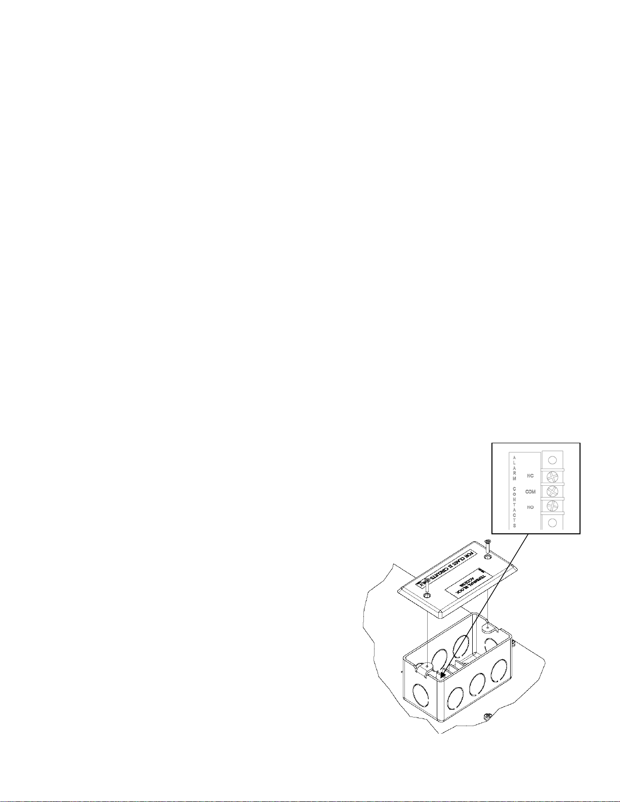
Remote Alarms Contacts Access - The factory installed Remote alarm contacts
access box is located at the top of the cabinet behind the microprocessor control
(see illustration.)
1. Remove the cover to access the terminal
connections.
2. Select and knock-out a hole to run field leads
into electrical box terminals.
3. The terminal block in the electrical box is
labeled for “normally open” and “normally
closed” activation. End user is responsible for
proper field installation.
Terminal connections are rated for class II
circuits only per NEC table 11(A). (Limited
power source less than 30vac 8 Amp. max, see
applicable notes in NEC).
2-10 volt DC Output – Terminal board for 2-10v DC
Output for temperature re-transmit is located behind
the cabinet façade, next to Remote Alarm access box. Connect wires as per label.
2 7/10 Rev. C 131783
Page 3

RS485 port - (Optional) terminal board for RS485 port is located behind the cabinet façade, next to
the Remote Alarm access box, connect wires as per label.
Duplex, or European Outlet 4 Amp Max. – (Optional) is located near the back of the left hand
interior wall, 20” from the cabinet interior floor. Outlet is wired thru main cabinet power supply, and
includes a 4 amp, MANUAL RESET, circuit breaker. Breaker is located behind façade, on the side
of the control box.
Access Port - (Optional) 2” port is provided with a spring loaded, exterior cover, RH or LH side of
the cabinet.
GLYCERIN WELL ASSEMBLY
Important: For accurate product temperature reading, the
product-sensing bulb must be immersed in glycerin solution
contained in the provided well.
One glycerin well is furnished with each model. The
purpose of the glycerin is to simulate the product stored in
the Incubator. The glycerin temperature reflects the
product's temperature during normal operation.
Figure 1
After the unit is put into operation, check to make sure that
the temperature indicating or alarm sensing bulb is
positioned inside the glycerin well as far as possible without
touching the well itself.
OPERATION
The Large Capacity Incubator is designed for an operating range of 5°C above room ambient to
70°C and is intended for indoor use only. A transverse blower optimizes airflow and ensures tight
temperature uniformity.
These units employ a programmable controller to control the temperature and CO2 option. The
controller is located on the facade of the unit. Please see the separate instructions, part number
113635, on the operation of the controller used in the Large Capacity Incubator.
The Incubator utilizes an electrically operated heater to warm the cabinet. The programmable
control is factory set with a cutout temperature of 70°C (158°F) to prevent the cabinet from
exceeding its design limitations.
NOTE: The cabinet is equipped with two switches located on the façade. One is the main power
ON/OFF switch for the unit. The other is a three-position switch for the battery-powered alarm. The
alarm switch is placed in the middle, or OFF position, for shipment. When the Large Capacity
Incubator is put into operation, the top of the switch should be pushed in to the ON position. With
the switch in the ON position, the battery will sound the alarm if the main power to the cabinet is
interrupted. The switch flipped to the bottom position is used to test the battery. This test must be
done with power
should be done periodically. The battery is located on the control box that is on top of the unit
behind the façade.
uninterrupted to the cabinet. The alarm will sound if the battery is good. This test
3 7/10 Rev. C 131783
Page 4

Figure A
DRAWER OPTION
The Large Capacity Incubator is offered with drawers as an option.
Drawer Removal – The Large Capacity Incubator may accommodate up to eight drawers. To
remove the drawers for cleaning, locate the black release tabs found on the inside front of the
drawer. See Figure C. Push the release tabs on each side inward and lift up the drawer. Slide the
drawer towards you and remove.
4 7/10 Rev. C 131783
Page 5

Figure C
Drawer Slide Removal/Adjustment – Each drawer slide is independently removable and can be
adjusted to different levels. First remove the drawer per above instructions. Release the locking
tabs located on the drawer slide, move the front tab up and release the tab in the back of the
cabinet, by sliding the locking tab towards the front. See illustration. Unhook the drawer slide
assembly from both the front and back shelf standards by lifting up on the assembly.
To install a drawer slide, reverse the process used to remove the slide. Secure the locking tabs into
position after the drawer slide assembly is in place. Reinstall the drawer.
MAINTENANCE
PERIODIC CLEANING
Beginning with the initial installation, the interior surfaces of the cabinet should be periodically wiped
down with a solution of warm water and baking soda. This solution will remove any odors from
spillage that has occurred. The exterior of the cabinet should also be cleaned frequently with a
commercial grade of glass cleaner. Caution: Do not use an abrasive or alkaline solution.
All moving parts have been permanently lubricated and will generally require no maintenance.
5 7/10 Rev. C 131783
Page 6

MAINTENANCE SERVICE AND ANALYSIS GUIDE
MALFUNCTION POSSIBLE CAUSE SOLUTION
No power to optional 1. Internal circuit breaker tripped 1. Reset circuit breaker
duplex receptacle 2. Wiring incorrect 2. Check wiring against the diagram
Heater inoperative 1. High limit thermostat tripped 1. Manually reset thermostat
2. Wiring incorrect 2. Check wiring against diagram
No power to cabinet 1. Service cord unplugged 1. Plug in service cord
2. Circuit breaker supplying 2. Determine reason and correct
main electrical receptacle tripped
3. Wiring incorrect 3. Check wiring against diagram
4. Main cabinet power switch off 4. Turn on power switch
Objectionable noise 1. Vibrating fan blade 1. Replace fan blade
2. Worn fan motor bearings 2. Replace fan motor
6 7/10 Rev. C 131783
 Loading...