

Page 1

LARGE CAPACITY CO2 INCUBATOR
Installation, Operation and
Maintenance Instructions
GENERAL
Inspection 2 Location 2
INSTALLATION
Door Alignment 2 Shelf Installation 2 Remote Contacts 2 2-10 Volt DC Output 2 RS485 Port 3 Duplex or European Outlet 4 Amp Max. 3 Access Port 3 Glycerin Well Assembly 3
OPERATION
CO
Humidity Pan Option 5
Operation 4
2
Drawer Option 5 Drawer Slide Removal/Adjustment 6
MAINTENANCE
Periodic Cleaning 6
2
2
3
6
Maintenance Service and Analysis Guide
1 11/10 Rev. B 143314
6
Page 2
GENERAL
Inspection
When the equipment is received, all items should be carefully checked against the bill of lading to
insure all crates and cartons have been received. All units should be inspected for concealed
damage by uncrating the units immediately. If any damage is found, it should be reported to the
carrier at once, and a claim should be filed with the carrier. This equipment has been inspected and
tested in the manufacturing facility and has been crated in accordance with transportation rules and
guidelines. Manufacturer is not responsible for freight loss or damage.
Location
The cabinet should also be leveled when it is placed in its permanent location. Do not stack items
on top of the unit. Vibration during shipping and handling may loosen mechanical connections.
Check all connections during installation. Check all wiring and fasteners.
CAUTION
• Do not modify cabinet construction or associated equipment assemblies.
• Do not remove labeling or information supplied with the unit.
Observe all Warning Labels. Disconnect power supply to eliminate injury from electrical
shock or moving parts when servicing equipment.
INSTALLATION
Door Alignment - If for some reason the doors are not squared up on the cabinet, the doors can be
adjusted. Opening the door(s) and loosening the screws that hold both the top and bottom hinges to
the cabinet can accomplish this. After adjusting the door so that it is aligned correctly, tighten the
screws to securely hold the hinges in place.
Shelving Installation - Locate shelves inside cabinet, install shelf supports (1 RH
support, 1 LH support per shelf.)
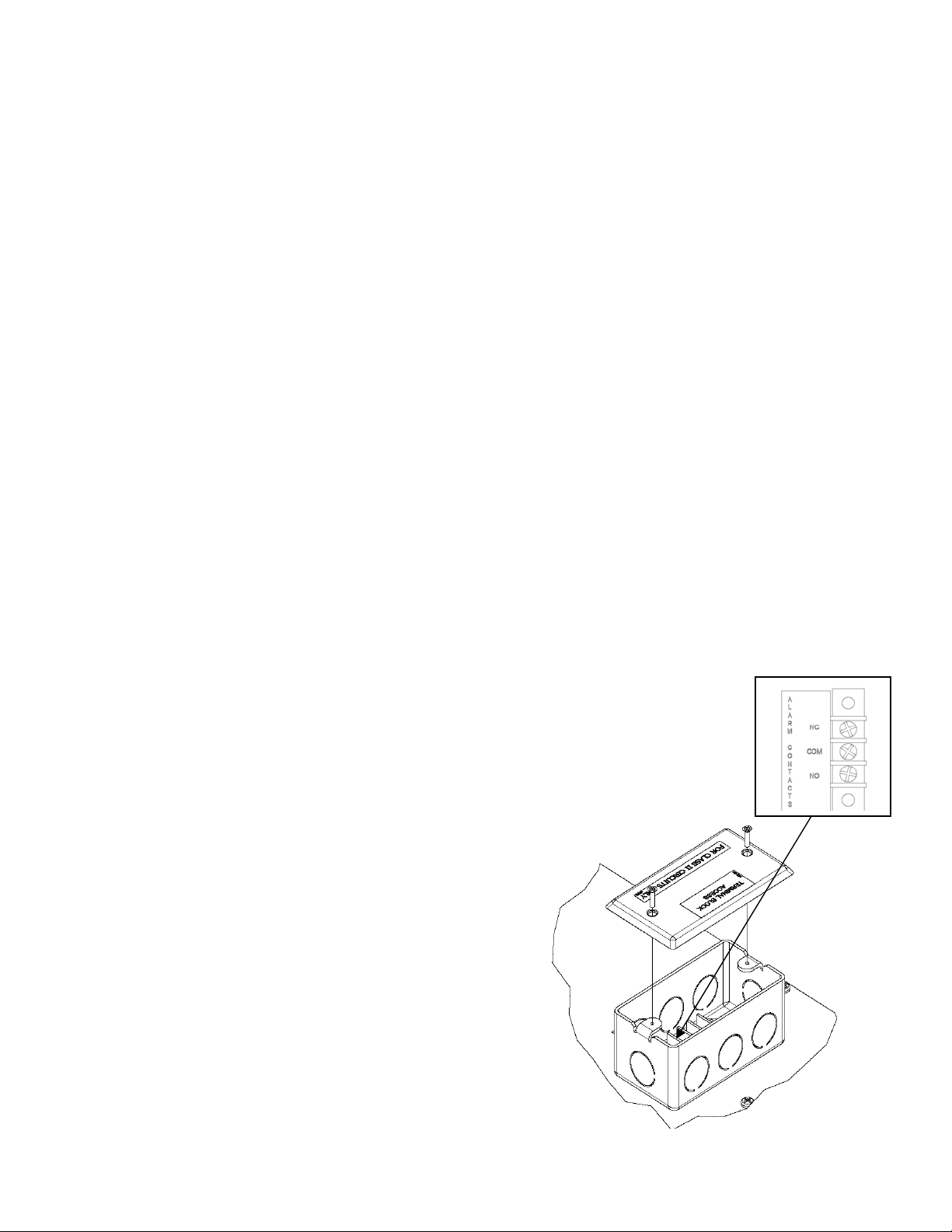
Remote Alarms Contacts Access - The factory installed Remote alarm contacts
access box is located at the top of the cabinet behind the microprocessor control
(see illustration.)
1. Remove the cover to access the terminal
connections.
2. Select and knock-out a hole to run field leads
into electrical box terminals.
3. The terminal block in the electrical box is
labeled for “normally open” and “normally
closed” activation. End user is responsible for
proper field installation.
Terminal connections are rated for class II
circuits only per NEC table 11(A). (Limited
power source less than 30vac 8 Amp. max,
see applicable notes in NEC).
2-10 volt DC Output – Terminal board for 2-10v DC
Output is located behind the cabinet façade, next to
Remote Alarm access box. Connect wires as per label.
2 11/10 Rev. B 143314
Page 3

RS485 port - (Optional) terminal board for RS485 port is located behind the cabinet façade, next to
the Remote Alarm access box, connect wires as per label.
Duplex, or European Outlet 4 Amp Max. – (Optional) is located near the back of the left hand
interior wall, 20” from the cabinet interior floor. Outlet is wired thru main cabinet power supply, and
includes a 4 amp, MANUAL RESET, circuit breaker. Breaker is located behind façade, on the side
of the control box.
Access Port - (Optional) 2” port is provided with a spring loaded, exterior cover, RH or LH side of
the cabinet.
Glycerin Well Assembly
Important: For accurate product temperature reading, the
product-sensing bulb must be immersed in glycerin solution
contained in the provided well.
One glycerin well is furnished with each model. The
purpose of the glycerin is to simulate the product stored in
the Incubator. The glycerin temperature reflects the
product's temperature during normal operation.
Figure 1
After the unit is put into operation, check to make sure that
the temperature indicating or alarm sensing bulb is
positioned inside the glycerin well as far as possible without
touching the well itself.
OPERATION
The Large Capacity Incubator is designed for an operating range of 5°C above room ambient to
70°C and is intended for indoor use only. A transverse blower optimizes airflow and ensures tight
temperature uniformity.
These units employ a programmable controller to control the temperature and CO2 option. The
controller is located on the facade of the unit. Please see the separate instructions, part number
113635, on the operation of the controller used in the Large Capacity Incubator.
The Incubator utilizes an electrically operated heater to warm the cabinet. The programmable
control is factory set with a cutout temperature of 70°C (158°F) to prevent the cabinet from
exceeding its design limitations.
Chamber CO
instrument.
sample port used for sampling chamber content using a FYRITE or similar
2
3 11/10 Rev. B 143314
Page 4

CO2 Operation
Figure A
The Large Capacity Incubator is offered with a CO2 dispensing and measurement system. The CO
system is microprocessor based and controlled by a sensor based on the NDIR Single-Beam DualWavelength principle. The sensor (included with CO
and provides a reliable and stable reference measurement over time. Water vapor, dust, debris and
most chemicals do not affect measurement accuracy; therefore, the sensor may be used in a harsh
and humid environment.
The CO
default and adjustable settings in the separate instructions, part number 136349.
Installation Requirements – The end user must supply two CO
regulators for the CO
above 4 psi as the CO
pressure drops to 4 psi.
psi.
Connecting a CO
settings are controlled by the controller located on the façade of the unit. Please see the
2
input. See Figure B for hook up points. The input gas pressure must be
2
tank switch over valve is factory set to recognize an empty tank when the
2
The maximum recommended input pressure should not exceed 25
Supply
2
option) measures from 0-20% CO2 density
2
tanks and two-two stage gas
2
High concentrations of carbon dioxide can cause
!
asphyxiation. The use of CO
is recommended for areas where CO
monitors and alarms
2
can collect.
2
2
4 11/10 Rev. B 143314
Page 5

CO2 Sample Port
The chamber atmosphere can be taken from the Sample Port located at the bottom of the front
control panel. CO
instrument such as a gas chromatograph.
concentration can then be checked using a FYRITE gas analyzer or other
2
Humidity Pan Option (CO2 Incubators only)
The Large Capacity Incubator humidity pan is manually filled with water as required. Humidity
(moisture) is introduced into the incubator interior by evaporation only.
The humidity pan is 22 Ga. stainless steel with dimensions of 20-3/4 inches long x 12-3/4 inches
wide x 2-1/2 inches deep. The pan capacity is 9 quarts (8.52 liters). A stainless steel pan cover is
also supplied.
Note: With the CO
/humidity pan feature, the cabinet is also provided with a drip pan that mounts
2
under the door. The drip pan catches any condensation that drips during door openings. The drip
pan is supplied with 4’ of 3/8” ID tubing and a 3/8” drain stopper. Tubing must be connected to
adequate drain or stopper needs to be installed and accumulated moisture removed as needed.
Figure B
Drawer Option
The Large Capacity Incubator is offered
with drawers as an option.
Drawer Removal – The Large Capacity
Incubator may accommodate up to eight
drawers. To remove the drawers for
cleaning, locate the black release tabs
found on the inside front of the drawer. See
Figure C. Push the release tabs on each
5 11/10 Rev. B 143314
Page 6

side inward and lift up the drawer. Slide the drawer towards you and remove.
Drawer Slide Removal/Adjustment
Each drawer slide is independently removable and can be adjusted to different levels. First remove
the drawer per above instructions. Release the locking tabs located on the drawer slide, move the
front tab up and release the tab in the back of the cabinet, by sliding the locking tab towards the
front. See illustration. Unhook the drawer slide assembly from both the front and back shelf
standards by lifting up on the assembly.
To install a drawer slide, reverse the process used to remove the slide. Secure the locking tabs into
position after the drawer slide assembly is in place. Reinstall the drawer.
Figure C
MAINTENANCE
Periodic Cleaning
Beginning with the initial installation, the interior surfaces of the cabinet should be periodically wiped
down with a solution of warm water and baking soda. This solution will remove any odors from
spillage that has occurred. The exterior of the cabinet should also be cleaned frequently with a
commercial grade of glass cleaner. Caution: Do not use an abrasive or alkaline solution.
All moving parts have been permanently lubricated and will generally require no maintenance.
MAINTENANCE SERVICE AND ANALYSIS GUIDE
MALFUNCTION POSSIBLE CAUSE SOLUTION
No power to optional 1. Internal circuit breaker tripped 1. Reset circuit breaker
duplex receptacle 2. Wiring incorrect 2. Check wiring against the diagram
Heater inoperative 1. High limit thermostat tripped 1. Manually reset thermostat
2. Wiring incorrect 2. Check wiring against diagram
No power to cabinet 1. Service cord unplugged 1. Plug in service cord
2. Circuit breaker supplying 2. Determine reason and correct
main electrical receptacle tripped
3. Wiring incorrect 3. Check wiring against diagram
4. Main cabinet power switch off 4. Turn on power switch
Objectionable noise 1. Vibrating fan blade 1. Replace fan blade
2. Worn fan motor bearings 2. Replace fan motor
measurement does not equal 1. Poor analyzer 1. Verify analyzer operation
CO
2
the display 2. Display not calibrated 2. Check calibration (see control manual)
measurement less than 1. CO2 regulator set too low 1. Adjust regulator (not to exceed 25 PSI)
CO
2
setpoint 2. Door recent opened or poor seal 2. Correct door seal
3. CO
4. Display not calibrated 4. Check calibration (see control manual)
and analyzer read zero 1. Loss of CO2 supply 1. Identify and correct
CO
2
(setpoint ok) 2. Defective solenoid 2. Replace solenoid
3. Supply tank(s) empty 3. Change tank(s)
tank(s) low 3. Change tank(s)
2
6 11/10 Rev. B 143314
 Loading...