

Page 1

1
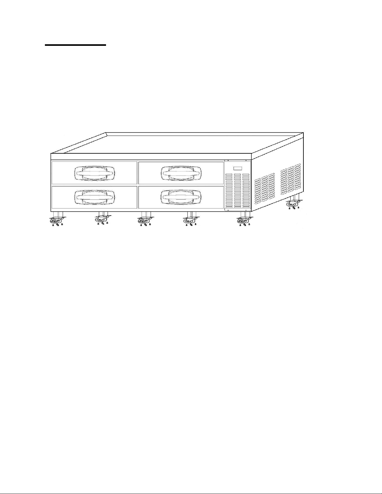
CHEF BASE CABINETS
Installation, Operation and Maintenance Instructions
INSPECTION
When the equipment is received, all items should be carefully checked against the Bill
of Lading to ensure all crates and cartons have been received. Do not sign the freight
bill clear until the freight has been properly inspected for damage. All units should be
inspected for damage including concealed damage by uncrating immediately. If any
damage is found, it should be reported to the carrier at once, noted on the Bill of Lading
and a claim should be filed with the carrier. This equipment has been inspected and
tested in the manufacturing facility and has been crated in accordance with
transportation rules and guidelines. The manufacturer is not responsible for freight loss
or damages.
INSTALLATION
The exterior top of the cabinet has been protected by a plastic covering. Peel this
protective covering before installation. After removing the covering, clean the interior
and exterior surfaces of the unit with soap and water and a rinse with clean water. Do
not use chlorinated cleaners on the surfaces as they can cause corrosion.
The refrigeration system located on the side of the unit requires free air access for
proper operation. Allow a minimum of seven inches between the back of the cabinet
and the wall. The equipment is designed to accept heat generating cooking equipment if
the equipment is properly installed with legs (supplied by the cooking equipment
manufacturer). A minimum clearance of 4 inches is required between the bottom of the
cooking equipment heating element and the cabinet top. Failure to provide adequate
clearance voids manufacturer warranty. Installation of a heat shield (supplied by others)
is recommended for optimum performance.
Confirm that the proposed electrical outlet has the correct voltage, frequency and
current carrying capacity for the requirements of the unit. This information is noted on
the data plate on the inside left wall of the unit. The unit should be isolated on a circuit.
Do not use an extension cord to get power to the unit. Improper electrical installations
will void the compressor warranty. To prevent shock and fire, be sure the unit is properly
grounded.
The temperature controller is located inside the refrigerated compartment in the back
right top corner. The default temperature is set at “normal”. Adjust the temperature to fit
your needs. It is not recommended that the cabinet be run colder than +35°F.
08/13 Rev. E 147774
Page 2
2
CAUTION!
DO NOT SIT OR STAND ON TOP OF THESE CABINETS AND
DO NOT USE THE DRAWERS AS A STEP.
SERIOUS INJURIES CAN OCCUR.
Install casters per the following diagram.
Note: Install casters with brakes to the front of the cabinet.
MAINTENANCE
General Cleaning
Beginning with the initial installation, the interior surfaces of the cabinet should be
periodically cleaned with a solution of warm water and baking soda. This solution will
remove any odors from spillage that has occurred. The exterior of the cabinet should
also be cleaned frequently with a commercial stainless steel cleaner, glass cleaner or
mild soap solution. Do not use chlorinated cleaners on the stainless steel surfaces.
The door gaskets should be cleaned in place with a mild soap solution to extend their
life.
Condenser Coil Cleaning
Prior to cleaning the condenser coil disconnect the unit from power. Periodic cleaning
of the condenser coil will aid the heat transfer of the refrigeration system and increase
its efficiency. To accomplish this, remove the front grill from the cabinet. The
condenser coil is located behind the grill. Use a soft bristled brush to remove any dirt
particles that are on the fins of the condenser coil. Use a vacuum cleaner or
compressed air to remove the loosened particles. Replace the grill and reconnect the
unit to power. Failure to clean the condenser coil can lead to performance loss and
compressor failure. It is recommended a minimum of every three months.
08/13 Rev. E 147774
Page 3
3
TROUBLESHOOTING
Problem Remedy
· Check the power cord and make sure it is plugged in.
Compressor will
not start
Poor
performance
· Check the temperature controller. If it is in the “OFF” position,
turn it clockwise to set a desired temperature.
· Move the unit from direct sunlight.
· Move the unit away from heating devices.
· Install the unit in a well ventilated place, with at least 7 inches of
clearance on all sides.
· Clean the condenser if heavy dust is collected.
· Clear contents from bloc ki ng the air duct.
· Check the temperature controller for incorrect setting.
· Check the refrigerant level, it may need to be charged.
· Check the door and be sure it is completely closed.
Unit noisy
Condensation on
cabinet exterior
and/or floor
· Install the unit on a level surface.
· Maintain 7 inches of clearance from the wall.
· Check for loose part or mounting.
· Keep the tubing free from any contact to avoid rattle.
· Reduce humidity where the unit is installed.
· Repair or replace the gasket on the door.
08/13 Rev. E 147774
Page 4

4
SPECIFICATIONS
9.8 CuFt
(277 liter)
9.8 CuFt
(277 liter)
14.3 CuFt
(405 liter)
17.2 CuFt
(487 liter)
21.4 CuFt
(606 liter)
2 Large
2 Small
PRODUCT CHEF BASE
MODEL CB53 CB60 CB72 CB84 CB96
Capacity
(W) 53.0” 60.0” 72.0” 84.0” 96.1”
Exterior
Dimensions
(including
casters)
(D) 31.0”
(H)* 25.5”
Drawers 2 Large 2 Large 4 Small
Pan Quantity 6 Full Size 6 Full Size 8 Full Size 10 Full Size 12 Full Size
Compressor 1/5 HP 1/5 HP 1/5 HP 3/8 HP 3/8 HP
Power Voltage 115V / 60Hz
Plug In-Installation NEMA 5-15P
Amps 3.3 3.3 3.3 6.0 6.0
Range of Temperature +35°F ~ 40°F
Refrigerant R-134a
Net Weight (lbs) 230 250 340 355 390
4 Large
* Includes 5 inches for casters.
** Above specifications are subjected to change without prior notice for quality improvement.
*** Relative humidity should be kept between 30% - 60%, maintaining a dew point of +50°F or less.
08/13 Rev. E 147774
Page 5

5
ITEM
NUMBER
PART NAME DESCRIPTION CB53 CB60 CB72 CB84 CB96 P/N
1 Cabinet Rail Assy - Left X X X X X 149811
2 Cabinet Rail Assy - Right X X X X X 149812
3 Crossbar Rail Assy - Left X X X 149813
4 Crossbar Rail Assy - Right X X X 149814
5 Tray Frame - Big STS445NF X X X X 149815
6 Tray Frame - Small STS445NF X X 149816
7 Door Assy - Big STS430, URT, 53,60, 83(86)(84), 96 X X X X 149817
8 Door Assy - Small STS430, URT, 71(74)(72), 83(86)(84) X X 149818
9 Door Gasket PVC-S 71(74)(72), 83(86)(84) X X 149819
10 Door Gasket PVC-S 53,60, 83(86)(84), 96 X X X X 149820
11 Condenser 10S*4R, 3/16" ST X X X 149821
12 Condenser 10S*6R, 3/16" ST X X 149822
13 Condenser - Hot Pipe OD 1/3" CU Pipe X X X X X 145712
14 Evaporator Assembly 4S*3R, 3/8" CU, 342mm X X X 149823
15 Evaporator Assembly 4S*3R, 3/8" CU, 700mm X X 149824
16 Drier XH-9, 18g X X X X X 145714
17
Capillary & Suc Pipe Assy cu pip
7.94, ID1.2 x L1650 X X X X X 149825
18 Thermostat Control GNA-240L X X X X X 145727
19 Knob ABS X X X X X 145730
20 Thermostat Plate Stainless Steel X X X X X 145821
21 Compressor SD162C-L1U, 53,60, 71,72 X X X 145735
22 Compressor SK1A1C-L2W, 83,84, 96 X X 145736
23 Harness Main AWM1015 X X X X X 149826
24 Harness Comp. AWM1015(SK162C-L1U) X X X 149827
25 Harness Comp. AWM1015(SK1A1C-L2W) X X 149828
26 Main Power Cord 125V 15A X X X X X 145733
27 Indicator TID-1110 - 115V, °F X X X X X 149829
28 Condenser Fan Motor 115V/6W/CW X X X X X 145751
29 Condenser Fan Motor Blade AL, Φ110 X X X X X 145750
30 Evaporator Fan Motor 115V/60Hz, DAI6122 FRTA X X X X X 145709
31 Evaporator Fan Blade ABS, Φ110 X X X X X 145710
32 Supporter Pan (A) STS445NF, T1.0 X X X X X 149830
33 Supporter Pan (B) STS445NF, T1.0 O O O O O 149831
34 Side Cover STS430 X X X X X 149832
35 Front Cover STS430 X X X X X 149833
36 Back Cover GI X X X X X 149834
37 Evap. Fan Guard - Small STS445NF X X 149835
38 Evap. Fan Guard - Large STS445NF X X X 149836
39 Evap. Duct (2 fan) STS445NF X X 149837
40 Evap. Duct (3 fan) STS445NF X X X 149838
41 Caster Set 4" 1 Brake Caster & 1 Regular Caster X X X X X 149839
08/13 Rev. E 147774
Page 6

6
▣Chef Base – Drawer Structure
Small drawers
Large drawers
Tray Frame Assy – small – ITE M 6
Door Gasket – small – ITEM 9
Door Assembly- small – I TEM 8
Supporter Pan – A – ITEM 32
Tray Frame Assy – big – ITEM 5
Door Gasket – big – I T E M 10
Door Assembly- big – ITEM 7
Supporter Pan – A – ITEM 32
▣Chef Base – Drawer Rail Structure
Cabinet Rail - Left – ITEM 1
Crossbar Rail – Left – ITEM 3
Crossbar Rail – Right – ITEM 4 Cabinet Rail – Right – ITE M 2
08/13 Rev. E 147774
Page 7

7
▣
Chef Ba se
– Internal Structure
REF-Thermostat Kit
Control – ITEM 18
Knob – ITEM 19
Plate – ITEM 20
EVAP. FAN GUARD
Small
– ITEM 37
Large – ITEM 38
Drain Pan(Drip)
EVAP. DUCT (3F)
2 Fan –
ITEM 39
3 Fan – ITEM 40
EVAPORATOR
Small – ITEM 14
Large – ITEM 15
Evaporator Fan Motor
Motor –
ITEM 30
Blade – ITEM 31
▣
Chef Base –
Machi ne
Room
Disassembly
REAR COVER
ITEM 36
SIDE MACHINE
COVER
ITEM 34
FRONT
COVER
ITEM 35
INDICATOR
ITEM 27
▣ Chef Base – Machi ne
Room
Condensing Uni t Disassembl y -2
Unit Base
Condenser -
ITEM 11
- ITEM 12
Evaporating pan (dish)
Hot Pipe – ITEM 13
Condenser fan motor – Assembly
Motor
– ITEM 28
Blade -
ITEM 29
Compressor –
ITEM 21
- ITEM 22
CAPILLARY & SUCTION PIPE ASSY –
ITEM 17
Dryer
– ITEM 16
HARNESS MAIN
ITEM 23
HARNESS COMP
Compressor Type [SD162C-L1U]
ITEM 24
HARNESS COMP
Compressor type [SK1A1C-L1U2]
ITEM 25
08/13 Rev. E 147774
Page 8

8
▣ Chef Base – Wiring Diagram
[CB53, CB60, CB72]
▣ Chef Base – Wir ing Diagr am
[CB84,CB96]
08/13 Rev. E 147774
 Loading...