

Page 1

LS-600/LS-1100
Installation Manual
Before installation, carefully read and understand Workflow explained in this Installation
Manual.
For details, see
☞1.1 Workflow (Windows XP) or ☞1.2 Workflow (Windows Vista).
Page 2

Page 3

Preface
We greatly appreciate your purchase of this product.
Before using this product, read the manual carefully, and make sure that you understand the procedure described. Be sure to
store the paper manual near the product so it can be referred to immediately should you have questions about operation or
should any problems arise.
If you should lose or heavily damage the manual, contact your place of purchase.
[Issued in June, 2008]
! It is prohibited to copy or reproduce this manual.
! The manual is subject to change without notice.
! Illustrations in the manual may vary depending on the model or manufacturing lot.
! If should you find any unclear points or errors, or should you have any comments for the manual, please contact your place
of purchase.
! If there is a missing page or incorrect pagination in this manual, please contact your place of purchase to receive a
replacement.
Page 4
ii
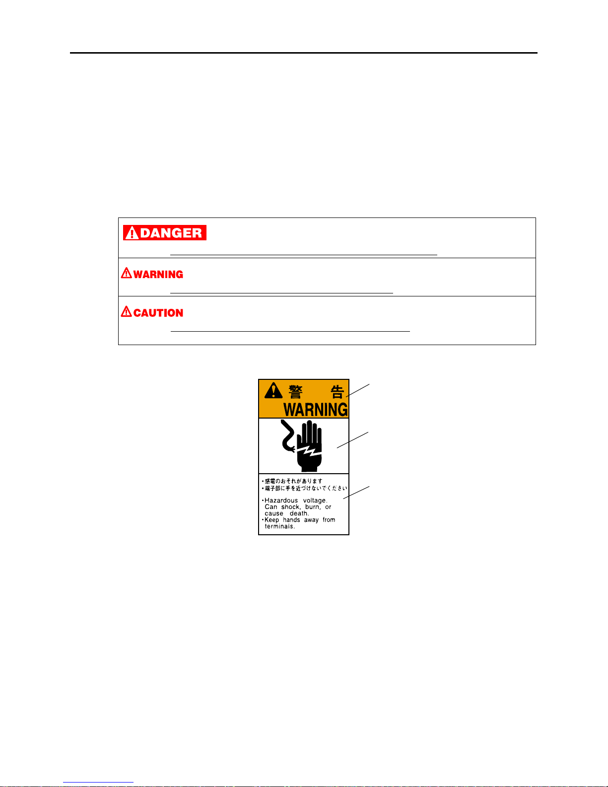
Description of warnings (signal words)
• Signal words identify the level of injuries that can potentially occur.
• The signal words used in this manual and found on labels, DANGER, WARNING and CAUTION, are assigned
according to the level of potential risk.
• Warning labels are located at or near the part of the system that poses the indicated danger. Ignoring a warning may
cause death or serious injury, or system malfunction. Be sure to follow the indications in the manuals and on the warning
labels.
• The warnings include a signal word, the type and extent of the danger, and information on avoiding the danger.
• Carefully read and understand the warnings included in this manual and on the warning labels before operating the
system.
Example of warning label
This indicates situations that if not immediately avoided could result in serious injury or death.
This indicates situations that if not avoided could result in serious injury or death
.
This indicates situations that if not avoided could result in non-life threatening injury
. It is also used to indicate situations
which may cause damage to physical property.
Warning text (warning
indication)
Symbol (warning indication)
Warning (signal word)
SIGNALWORD
Page 5
iii
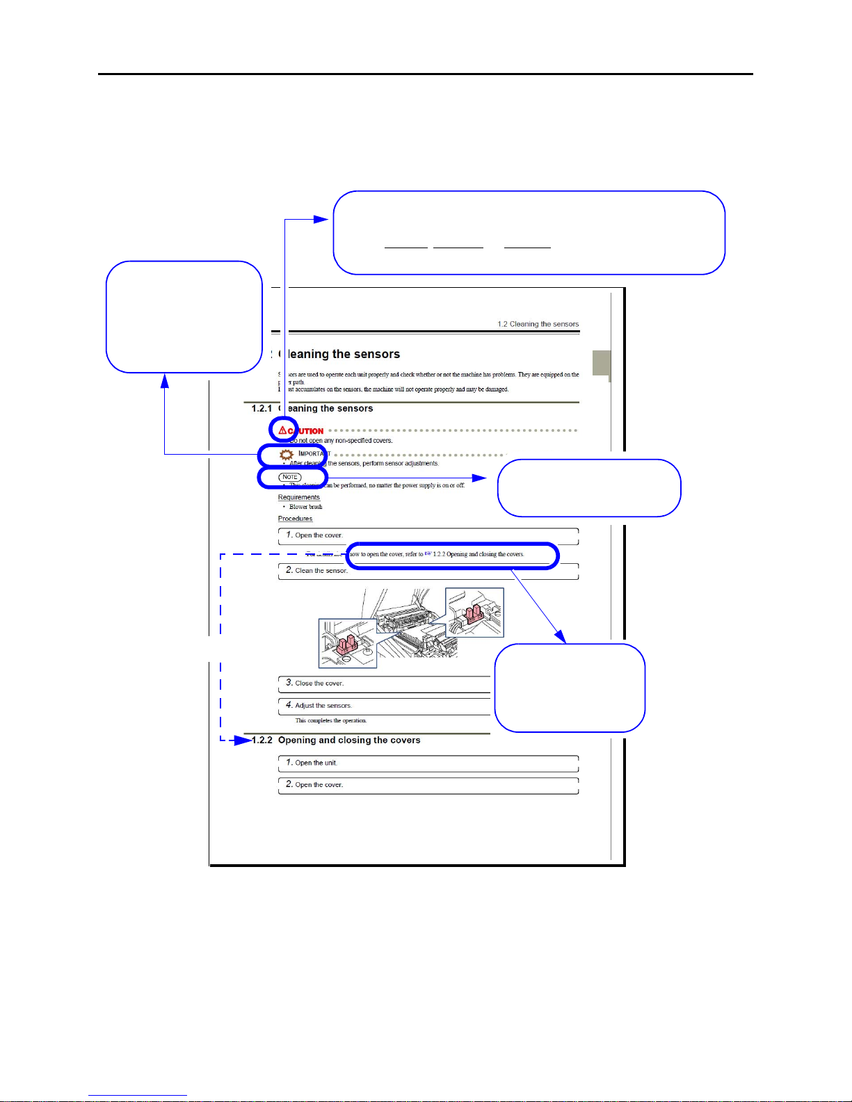
Symbols used in this manual
This section explains the definitions of the symbols used in this manual.
The symbols shown below are used in this manual. Confirm the meaning of each of them before reading the manual.
The pointing finger
indicates the manual or
section where you can find
additional information.
The Note symbol indicates useful
information on functions and
instructions.
The Important symbol indicate s
supplementary explanations,
operations or procedures that
require caution, and
instructions that must be
followed.
This is called the alert symbol.
Text following this symbol contains particularly important information concerning
safety. Be sure to heed this information. This symbol is used in conjunction with the
words DANGER
, WARNING and CAUTION, according to the possible degree of
injury to people or damage to physical property.
Reference
G068176
Page 6

iv
TABLE OF CONTENTS
Preface
Description of warnings (signal words) ...................................................................................................ii
Symbols used in this manual ................................................................................................................. iii
1 Before installation........................................................................................................................... 1
1.1 Workflow (Windows XP)....................................................................................................................................... 1
1.2 Workflow (Windows Vista) ................................................................................................................................... 2
1.3 Outline of connecting devices ................................................................................................................................ 3
1.4 Installation place..................................................................................................................................................... 3
1.5 Required items........................................................................................................................................................ 3
1.6 Removing packing angle brackets and antirust material........................................................................................ 4
2 Confirming the component parts .................................................................................................... 6
3 Configuring monitor display settings .............................................................................................. 7
4 Setting up the PC ......................................................................................................................... 12
4.1 Configuring power options................................................................................................................................... 12
4.2 Configuring the virtual memory........................................................................................................................... 15
4.3 Configuring the Transfer Mode............................................................................................................................ 17
4.4 Turning off Autoplay of media drives.................................................................................................................. 20
4.5 Setting the taskbar ................................................................................................................................................ 23
4.6 Turning off the hotkey function (shortcut key function) on the resident application .......................................... 23
4.7 Configuring the User Account Control setting..................................................................................................... 24
4.8 Configuring Sidebar settings ................................................................................................................................ 25
5 Installing the TWAIN driver .......................................................................................................... 27
5.1 Installation procedure ........................................................................................................................................... 27
5.2 Installing the Windows Installer 3.1..................................................................................................................... 29
5.3 Installing the Microsoft Visual C++ 2005 SP1 Redistributable........................................................................... 30
5.4 Installing the Microsoft .NET Framework Version 3.0 ....................................................................................... 31
5.5 Installing the PostgreSQL8.1 ............................................................................................................................... 32
5.6 Installing the MSXML 4.0 SP2 Parser and SDK................................................................................................. 33
5.7 Installing the MSXML 6.0 Parser ........................................................................................................................ 36
5.8 Installing the Sentinel Protection Installer 7.3.0 .................................................................................................. 38
5.9 Installing the EZ Controller.................................................................................................................................. 41
5.10 Installing the EZ Controller ImgDataProc Additional Software.......................................................................... 41
5.11 Installing the System Capture............................................................................................................................... 43
6 Installing the SYSTEM PROGRAM.............................................................................................. 45
7 Connecting the power supply and setting the USB driver ............................................................ 49
7.1 Connecting the power supply............................................................................................................................... 49
7.2 Configuring USB driver settings.......................................................................................................................... 50
8 Configuring various settings......................................................................................................... 56
8.1 Configuring the USB power Management setting............................................................................................... 56
8.2 Configuring the installation date and display settings.......................................................................................... 58
8.3 Configuring the display unit and resolution name settings.................................................................................. 61
9 Creating print channels ................................................................................................................ 64
9.1 Creating print channels......................................................................................................................................... 64
Page 7

v
10 Quick reference ............................................................................................................................ 66
10.1 If installing TWAIN driver or SYSTEM PROGRAM failed............................................................................... 66
10.2 If connecting the USB cable and starting the PC before installing the scanner software.................................... 71
Page 8

This page is intentionally blank.
Page 9
1 Before installation
1
1 Before installation
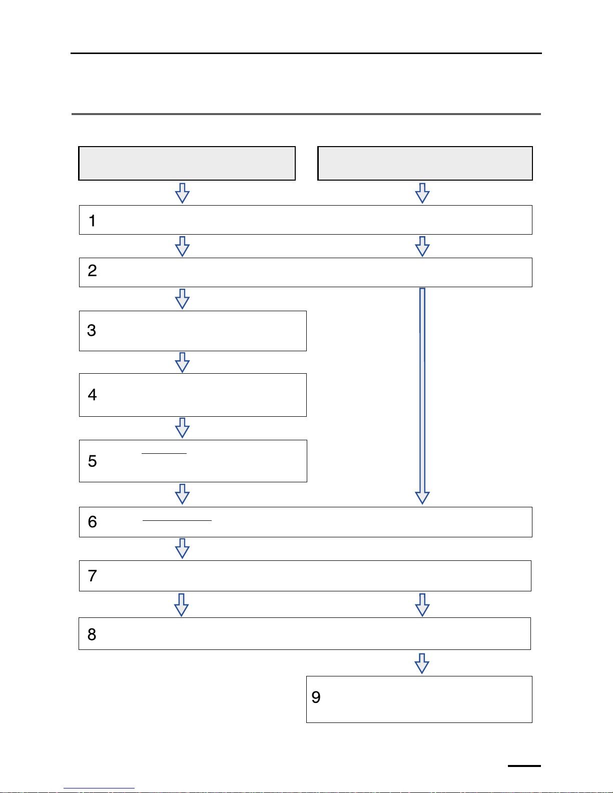
1.1 Workflow (Windows XP)
When connecting the scanner to the PC on which the controller is not
installed (our printer is not connected)
When connecting the scanner to the PC on which the controller is
installed (our printer is connected)
Confirming the component parts
See
☞2 Confirming the component parts to check that all the necessary items are prepared.
Configuring monitor display settings
• For details, see
☞3 Configuring monitor display settings.
Setting up the PC
• For details, see
☞4 Setting up the PC.
Installing the TWAIN driver
• For details, see ☞5 Installing the TWAIN driver.
Installing the SYSTEM PROGRAM
• For details, see ☞6 Installing the SYSTEM PROGRAM.
Connecting the power supply and setting the USB driver
• For details, see
☞7 Connecting the power supply and setting the USB driver.
Creating print channels
• For details, see
☞9 Creating print channels.
Configuring various settings
• For details, see
☞8 Configuring various settings.
Removing packing angle brackets and antirust material
• For details, see
☞1.6 Removing packing angle brackets and antirust material.
G089244
Page 10
1 Before installation
2
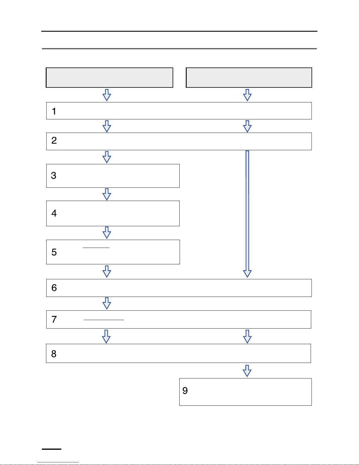
1.2 Workflow (Windows Vista)
When connecting the scanner to the PC on which the controller is not
installed (our printer is not connected)
When connecting the scanner to the PC on which the controller is
installed (our printer is connected)
Confirming the component parts
See
☞2 Confirming the component parts to check that all the necessary items are prepared.
Configuring monitor display settings
• For details, see
☞3 Configuring monitor display settings.
Setting up the PC
• For details, see
☞4 Setting up the PC.
Installing the TWAIN driver
• For details, see ☞5 Installing the TWAIN driver.
Installing the SYSTEM PROGRAM
• For details, see ☞6 Installing the SYSTEM PROGRAM.
Connecting the power supply and setting the USB driver
• For details, see
☞7 Connecting the power supply and setting the USB driver.
Creating print channels
• For details, see
☞9 Creating print channels.
Configuring various settings
• For details, see
☞8 Configuring various settings.
Removing packing angle brackets and antirust material
• For details, see
☞1.6 Removing packing angle brackets and antirust material.
G089244
Page 11
1 Before installation
3
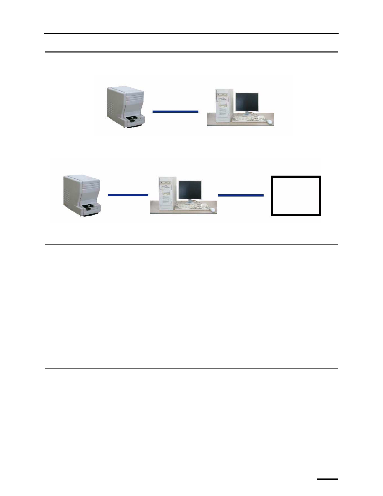
1.3 Outline of connecting devices
Example: If the scanner is connected to a PC on which the Controller is not installed
Example: If the scanner is connected to a PC on which the Controller is installed
1.4 Installation place
!!!! Weight
• LS-600: approx. 16.7 kg
• LS-1100: approx. 17.5 kg
!!!! Conditions for installation place
• Requires strength to support the scanner weight.
• Must be level, and not cause vibration. Vibration should be 3 m/s
2
(0.3 G) or less in each direction at the installation
place.
!!!! Conditions for power supply
• Confirm that a power supply with ground resistance of 100Ω or less is available.
1.5 Required items
The following items are required.
USB
Scanner
PC (prepared by users)
G087688
USB
LAN
Scanner
Printer
PC on which the Controller is
installed
G088478
Page 12
1 Before installation
4
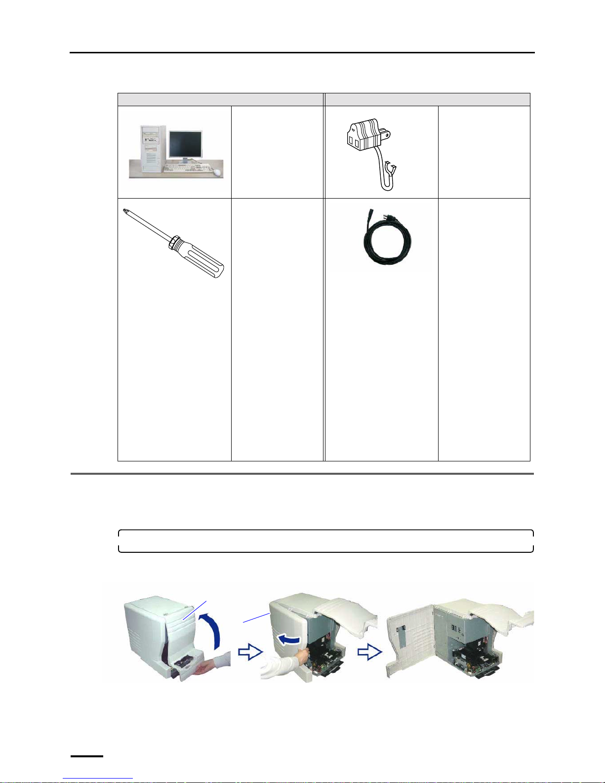
Confirm that the following items are prepared before you start working.
1.6 Removing packing angle brackets and antirust material
The removed packing angle brackets are not reused. However, they are necessary when the product is sent back because of
failure, etc. Be sure to keep them.
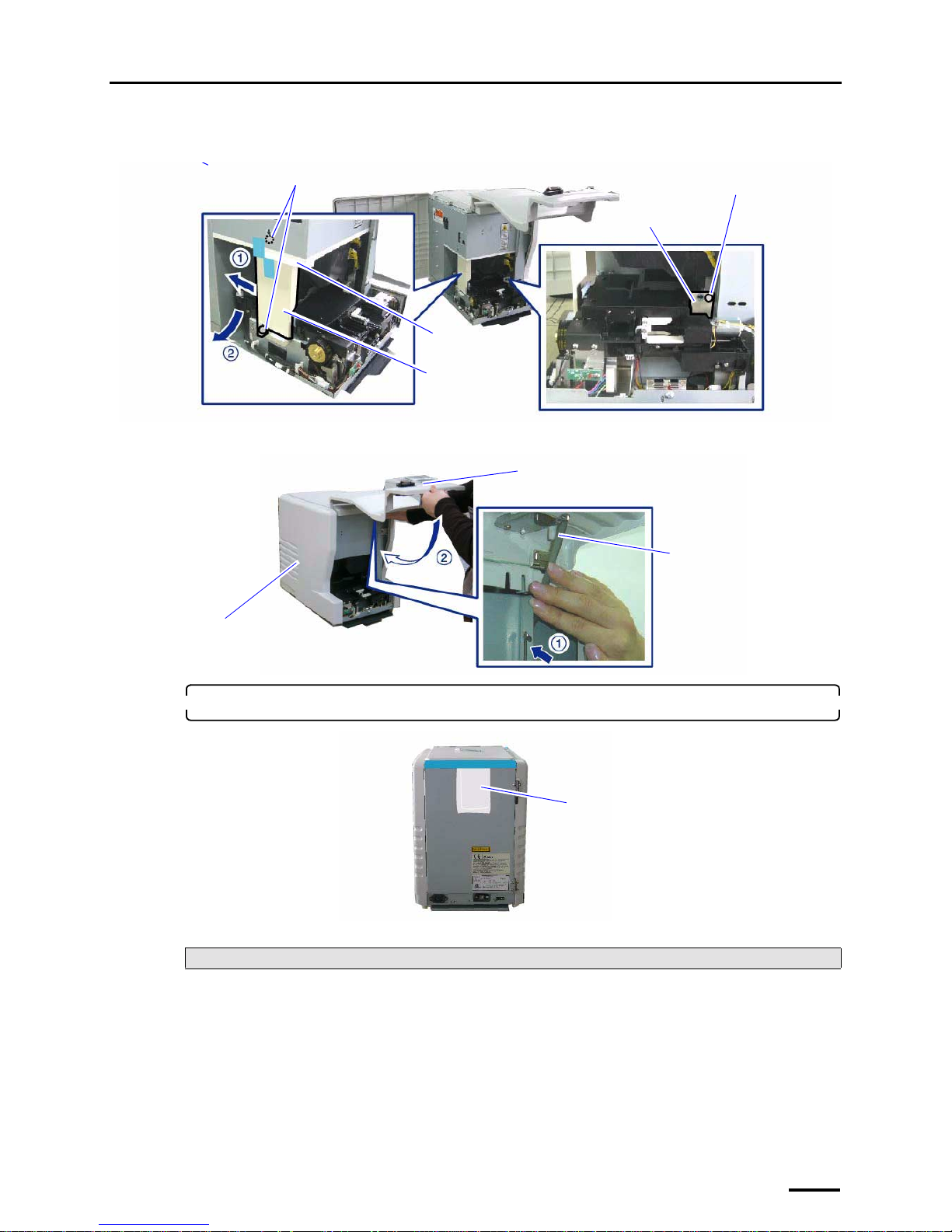
1. Remove the packing angle brackets.
(1) Open the front cover and side cover (left).
Required item Required item
PC
(See the Specifications
for details about the
recommended
specification of the PC)
Grounding adapter
(as necessary)
Philips blade screwdriver
(large)
Power cord
(Power code is supplied
in Japan and North
America. For other
countries, prepare a
power code that meets the
following specifications.)
• Input voltage: 250 V
(220 V-240 V) and
rating capacity of 6
A or more
• Plug type:
acceptable one in
each country
• Cable type: one of
the following type
and 19 AWG (0.75
mm
2
) or more
• 20195
• SJT
• SVT
• UL/CSA/VDEapproved products
Front cover
Side cover
G087613
Page 13
1 Before installation
5
(2) Remove packing material, packing angle bracket 1 (two screws) and packing angle bracket 2 (one
screw).
(3) Press the side cover (left) and the holder, then securely close the front cover.
2. Remove the antirust material from the back of the product.
This completes removing packing angle brackets and antirust material.
Next, go to ☞2 Confirming the component parts.
Packing angle
bracket 2
Screw
Packing angle
bracket 1
Screws
Packing material
G088628
Holder
Side cover (left)
Front cover
G088629
Antirust material
G088441
Page 14
2 Confirming the component parts
6
2 Confirming the component parts
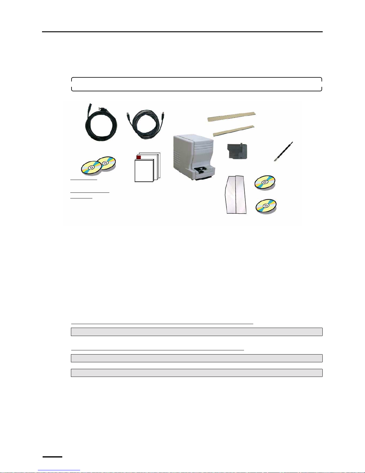
Confirm that all components are supplied.
1. Confirm the component parts.
Check whether all components are supplied.
Following components are used when installing this system.
• Power cord
*3
• USB cable
• TWAIN driver (CD-ROM), LS-# # # # SYSTEM PROGRAM (CD-ROM)
*2
• Manual
*1. Used only for connecting the scanner to the PC on which the controller is not installed.
*2. The model name is shown in # # # #.
*3. Supplied only in Japan and North America.
This completes confirming the component parts.
"
""
" Next, go to • • •
If connecting the scanner to the PC on which the controller is not installed
If connecting the scanner to the PC on which the controller is installed
Perform ☞3 Configuring monitor display settings.
For Windows XP, go to ☞6 Installing the SYSTEM PROGRAM.
For Windows Vista, go to ☞7 Connecting the power supply and setting the USB driver.
Scanner
Power cord
*3
USB cable
• TWAIN driver
(CD-
ROM)
*1
• L S - # # # # SYSTEM
PROGRAM (CD-ROM)
*2
135 cleaning leader
Cleaning leader case
IX240 adapter
240 cleaning leader B
Maintenance stick
Manual
• Installation Manual
• Starting Guide
• Specifications
• License agreement
CD manual
CD parts list (only
for outside Japan)
G087641
Page 15
3 Configuring monitor display settings
7
3 Configuring monitor display settings
This operation is not necessary if the Controller is installed on the PC.
For Windows XP
1. Start the PC.
Turn on the power of the display monitor.
2. Right-click on the desktop, and select Properties.
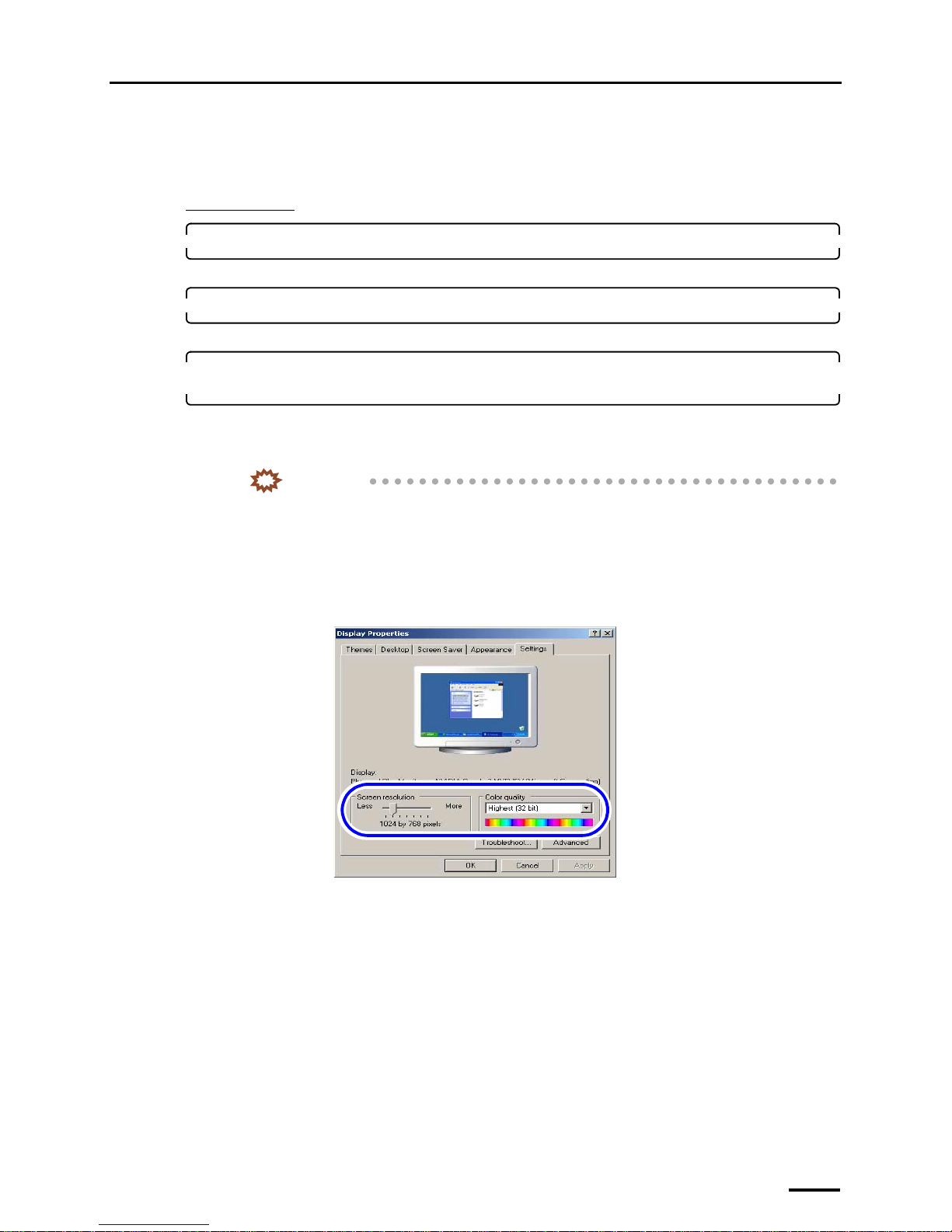
The Display Properties display is shown.
3. Select the Settings tab to configure the resolution setting and color setting of the monitor
display.
Configure the resolution and color settings of the display monitor as shown below.
• Screen resolution
Match the resolution to the recommended resolution of the monitor.
IMPORTANT
• Confirm the recommended resolution in the Operator's Manual of the monitor.
Example:
• If the recommended number of pixels is 1024×768: 1024×768 pixels
• If the recommended number of pixels is 1280×1024: 1280×1024 pixels
• Color quality
Highest (32 bit)
S088116
Page 16
3 Configuring monitor display settings
8
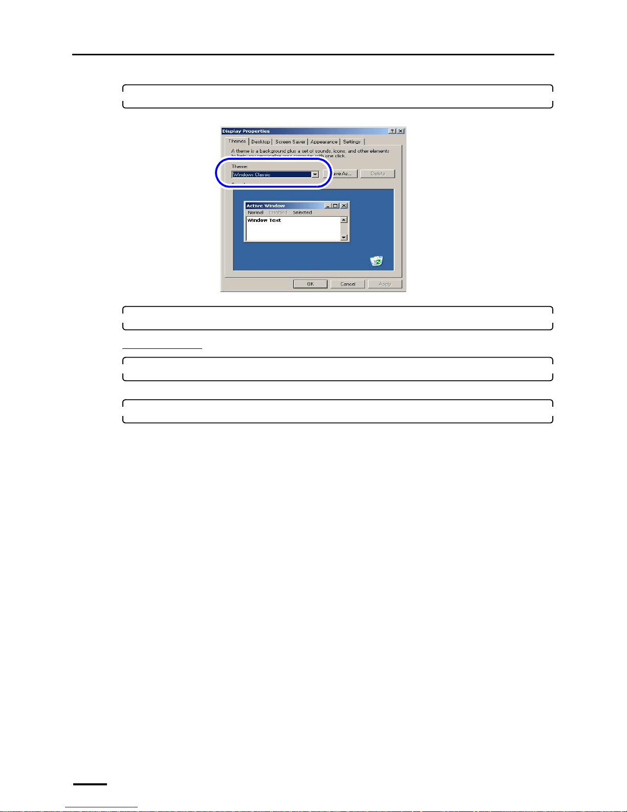
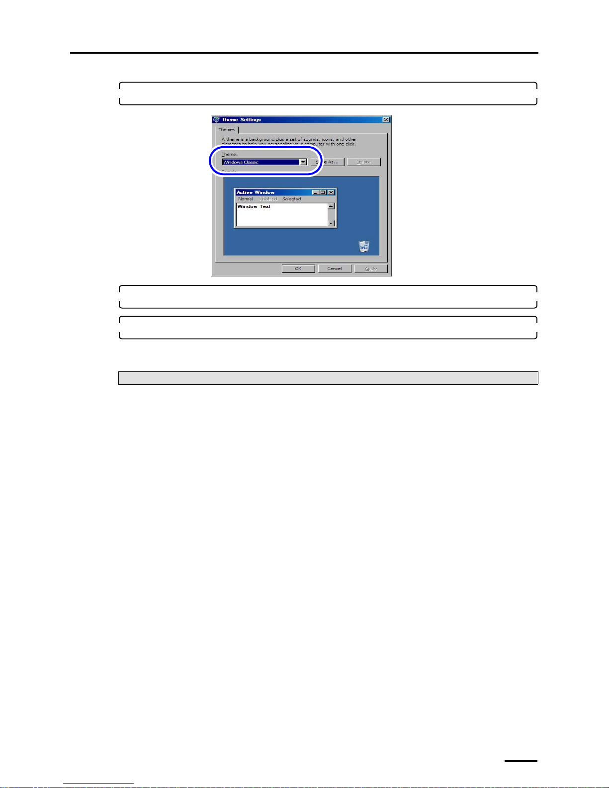
4. Select Windows Classic for Theme in the Themes tab.
5. Click OK.
For Windows Vista
1. Start the PC.
Turn on the power of the display monitor.
2. Access the Personalization display.
Bringing up the display
Start → Control Panel → Appearance and Personalization → Personalization
S088407
Page 17
3 Configuring monitor display settings
9
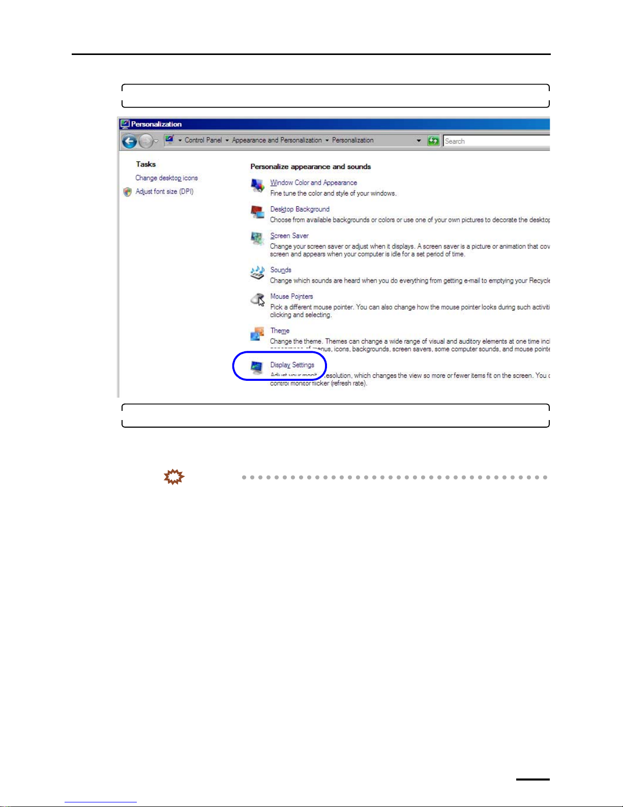
3. Click Display Settings.
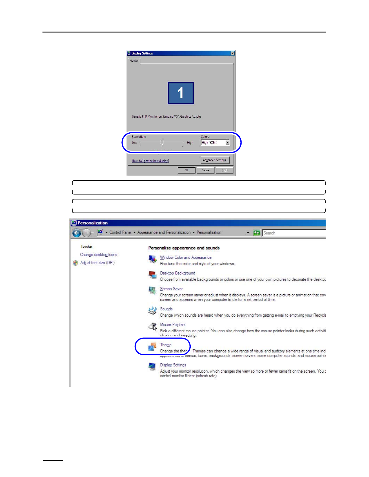
4. Configure the Resolution and Colors settings.
Configure the resolution and color settings of the display monitor as shown below.
• Screen resolution
Match the resolution to the recommended resolution of the monitor.
IMPORTANT
• Confirm the recommended resolution in the Operator's Manual of the monitor.
Example:
• If the recommended number of pixels is 1024×768: 1024×768 pixels
• If the recommended number of pixels is 1280×1024: 1280×1024 pixels
• Color quality
High (32 bit)
S091811
Page 18
3 Configuring monitor display settings
10
5. Click OK.
6. Click Theme.
S091796
S091811
Page 19
3 Configuring monitor display settings
11
7. Select Windows Classic for Theme.
8. Click OK.
9. Click the Close button at the upper right of the Personalization display to close it.
This completes configuring monitor display settings.
Next, go to ☞4 Setting up the PC.
S091797
Page 20
4 Setting up the PC
12
4 Setting up the PC
This operation is not necessary if the Controller is installed on the PC.
4.1 Configuring power options
For Windows XP
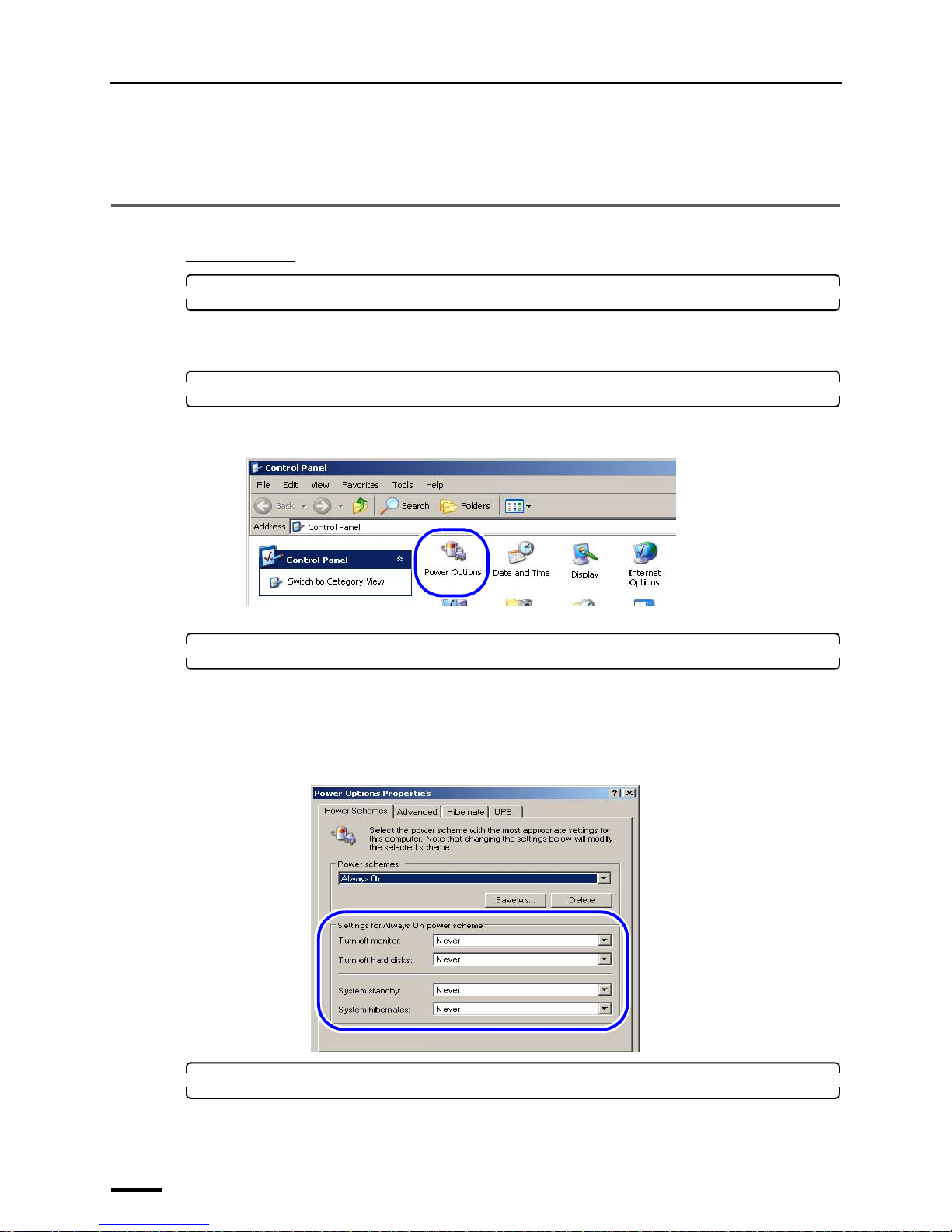
1. Access the Control Panel display.
Bringing up the display
Start → Control Panel
2. Double-click the Power Options icon.
The icon slightly varies depending on the OS.
Example:
The Power Options Properties display is shown.
3. Select Never for all the items below in the Power Schemes tab, and click OK.
• Turn off monitor
• Turn off hard disks
• System standby
• System hibernates
Example:
4. Click the Close button at the upper right of the Control Panel display to close it.
S079073
S088647
Page 21
4 Setting up the PC
13
For Windows Vista
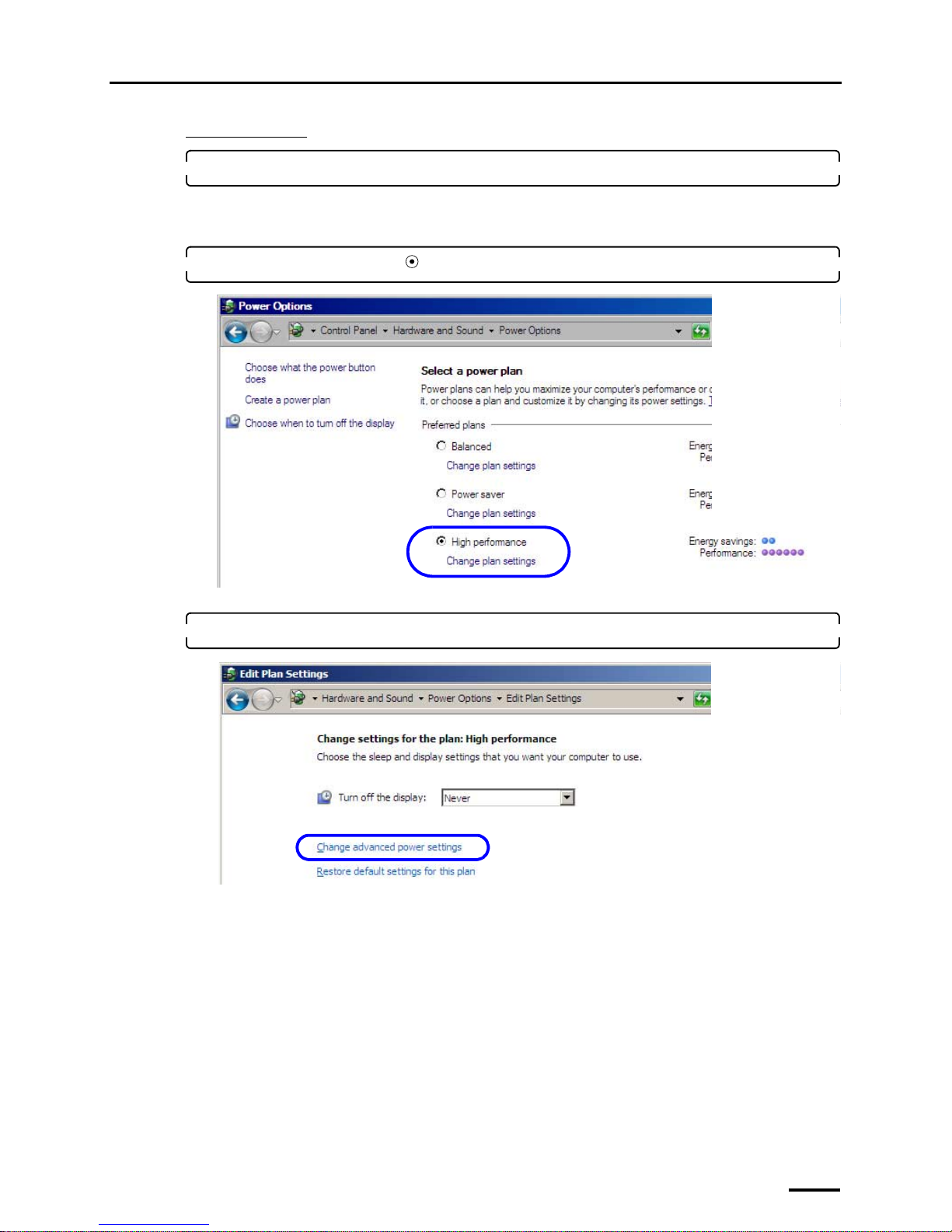
1. Access the Power Options display.
Bringing up the display
Start → Control Panel → Hardware and Sound → Power Options
2. Select High performance ( ) and click Change plan settings.
The Edit Plan Settings display is shown.
3. Click Change advanced power settings.
S091798
S091799
Page 22
4 Setting up the PC
14
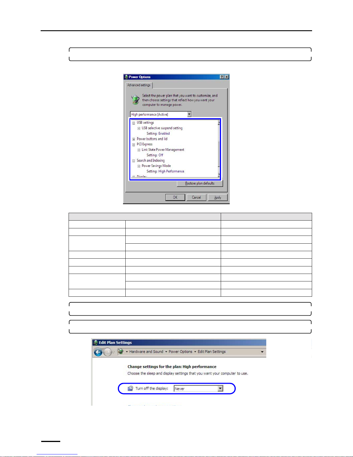
4. Configure the settings as shown below.
Some items may not be shown depending on the PC.
5. Click OK.
6. Select Never for Turn off the display: and click Save changes.
Item Setting
Hard disk Turn off hard disk after Never
Wireless Adapter Settings Power Savings Mode Maximum Performance
Sleep Sleep after Never
Hibernate after Never
USB settings USB selective suspend setting Disabled
PCI Express Link State Power Management Off
Search and Indexing Power Savings Mode High Performance
Display Turn off display after Never
Adaptive display Off
Multimedia settings When sharing media Prevent idling to sleep
S091801
S091799
Page 23
4 Setting up the PC
15
7. Click the Close button at the upper right of the Power Options display to close it.
This completes configuring power options.
4.2 Configuring the virtual memory
The displays slightly vary depending on the operating system, but the procedure is the same.
1. Access the System Properties display.
For Windows XP
(1) Access the Control Panel display.
Bringing up the display
Start → Control Panel
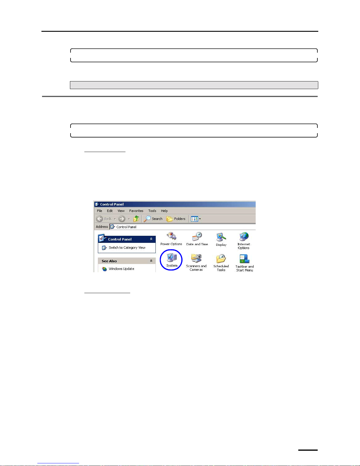
(2) Double-click the System icon.
Example:
The System Properties display is shown.
For Windows Vista
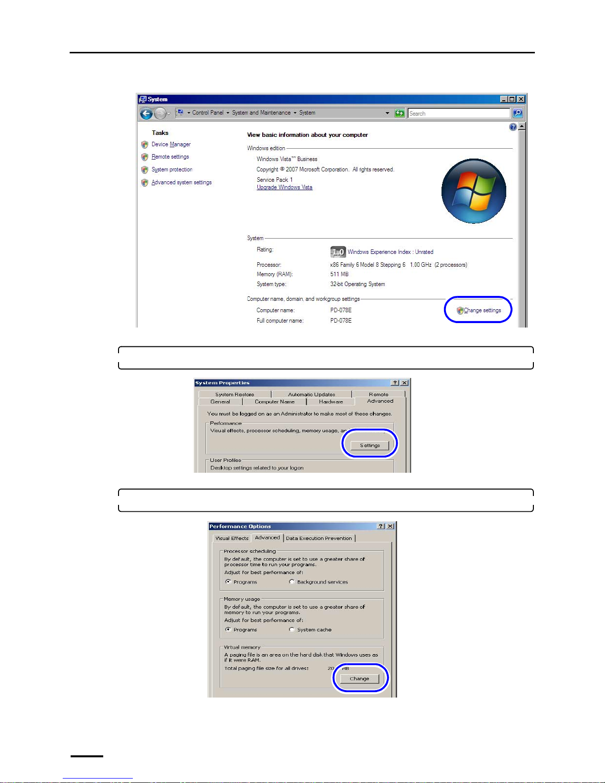
(1) Access the System display.
Bringing up the display
Start → Control Panel → System and Maintenance → System
Next, go to ☞4.2 Configuring the virtual memory.
S079073
Page 24
4 Setting up the PC
16
(2) Click Change settings.
The System Properties display is shown.
2. Click the Advanced tab, and click Settings of Performance.
The Performance Options display is shown.
3. Click the Advanced tab, and click Change of Virtual memory.
S091803
S088395
S088405
Page 25
4 Setting up the PC
17
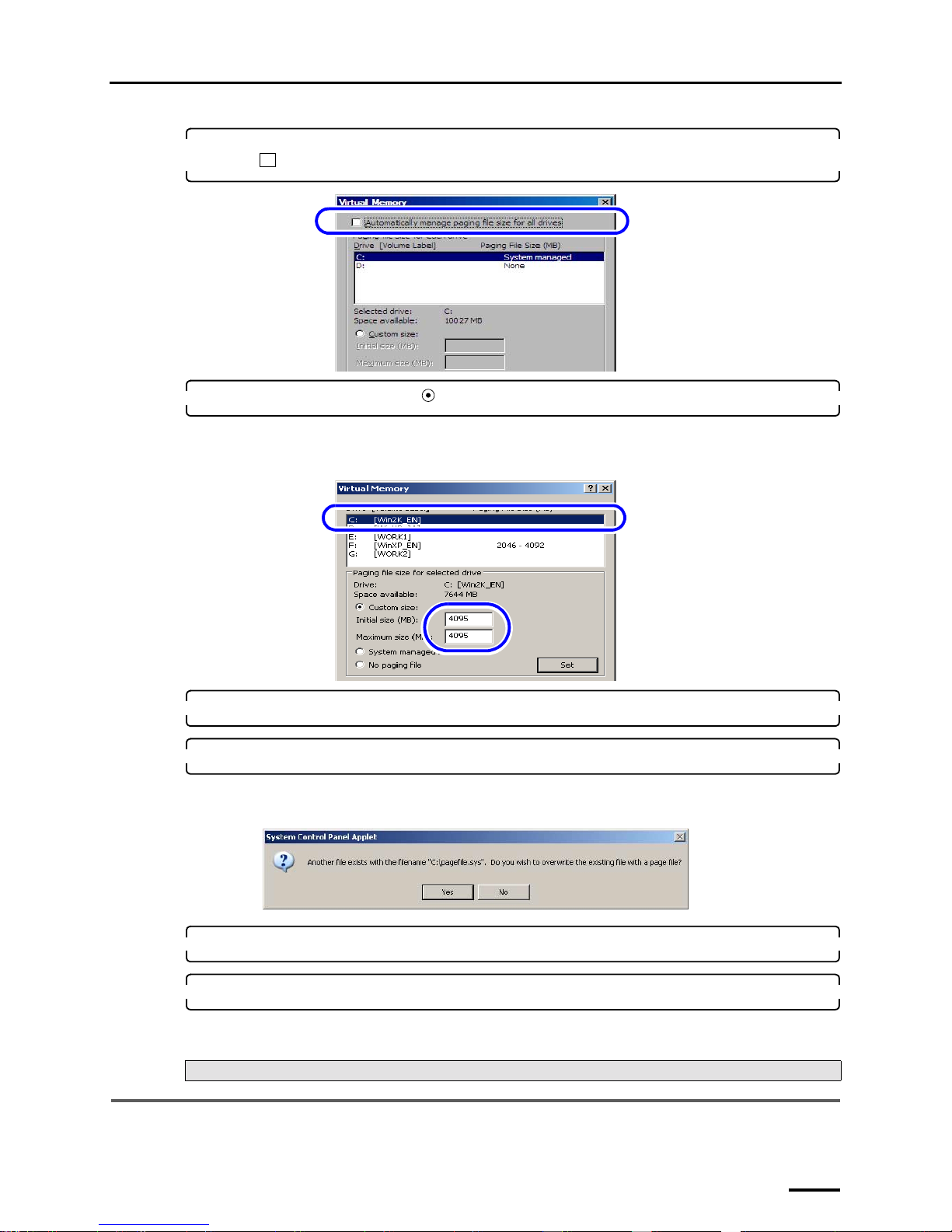
4. For Windows Vista, clear the Automatically manage paging file size for all drives check
box ( ).
5. Select the C drive and select ( ) Custom size, then configure the values as shown below.
• Initial size (MB): 4095
• Maximum size (MB): 4095
6. Click Set.
7. Click OK.
The following display may be shown depending on the settings of the PC. If the following display is shown, click
Yes.
8. Click OK to close the Performance Options and System Properties displays.
9. Click the Close button at the upper right of the display to close it.
This completes configuring the virtual memory.
4.3 Configuring the Transfer Mode
The displays slightly vary depending on the operating system, but the procedure is the same.
Next, go to ☞4.3 Configuring the Transfer Mode.
S091804
S088406
S088630
Page 26
4 Setting up the PC
18
1. Access the System Properties display.
For Windows XP
(1) Access the Control Panel display.
Bringing up the display
Start → Control Panel
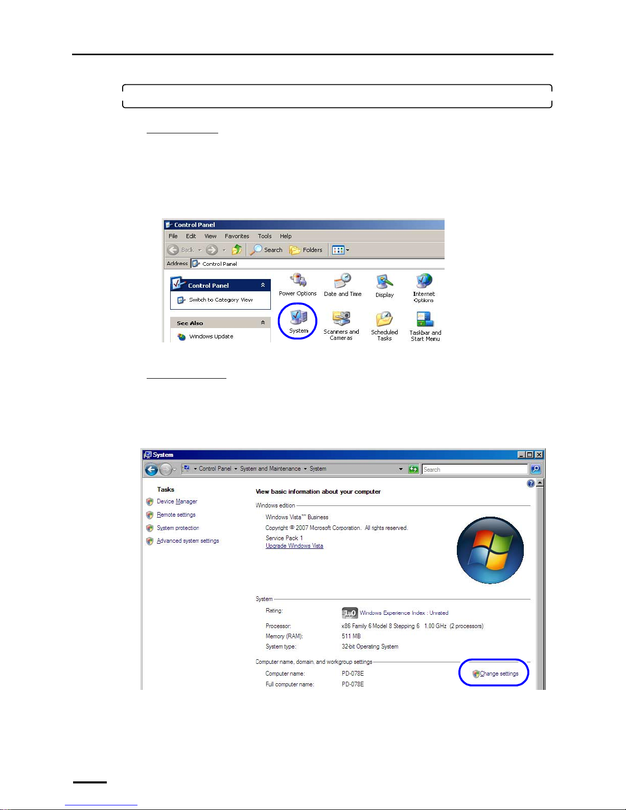
(2) Double-click the System icon.
Example:
The System Properties display is shown.
For Windows Vista
(1) Access the System display.
Bringing up the display
Start → Control Panel → System and Maintenance → System
(2) Click Change settings.
The System Properties display is shown.
S079073
S091803
Page 27
4 Setting up the PC
19
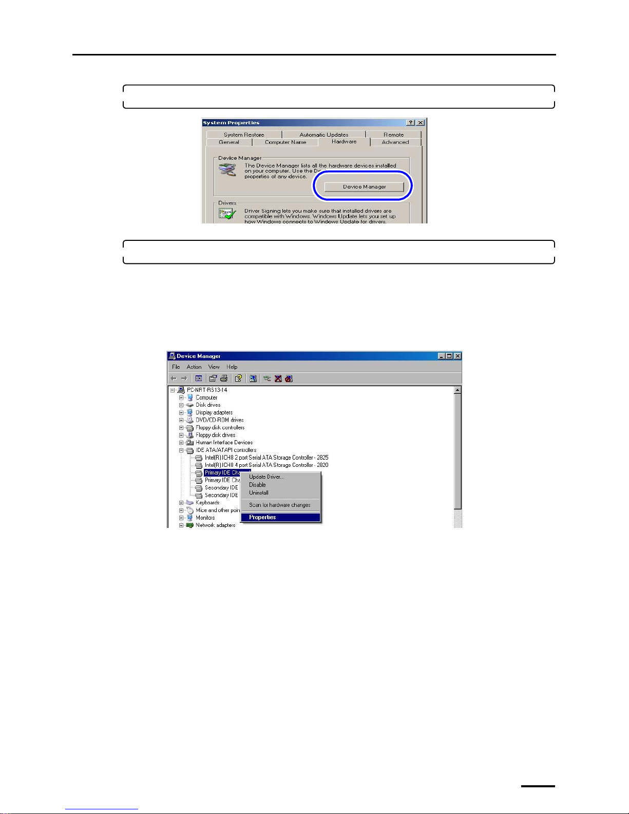
2. Select the Hardware tab and click Device Manager.
The Device Manager display is shown.
3. Access the Primary IDE Channel or Secondary IDE Channel display.
The displayed number of Primary IDE Channel and Secondary IDE Channel varies depending on the settings of
the PC. Configure all Primary IDE Channel and Secondary IDE Channel that are shown onscreen.
Bringing up the display
Double-click IDE ATA/ATAPI controllers on the Device Manager display. → Right-click Primary IDE
Channel or Secondary IDE Channel. → Click Properties.
Example: Primary IDE Channel Properties display
S088648
S088649
Page 28
4 Setting up the PC
20
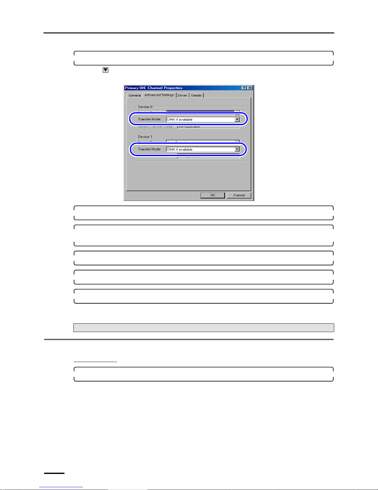
4. Select the Advanced Settings tab and configure Transfer Mode.
Click to select DMA if available for the Transfer Mode in Device 0 and Device 1.
Example: Primary IDE Channel Properties display
5. Click OK.
6. Configure the Transfer Mode setting for all Primary IDE Channel and Secondary IDE
Channel in the same procedure as Step 3 and Step 4.
7. Click × in the upper-right corner of the Device Manager display to close it.
8. Click OK to close the System Properties display.
9. Click the Close button at the upper right of the display to close it.
This completes configuring the transfer mode.
4.4 Turning off Autoplay of media drives
For Windows XP
1. Select Start → Run.
The Run display is shown.
Next, go to ☞4.4 Turning off Autoplay of media drives.
S088650
Page 29
4 Setting up the PC
21
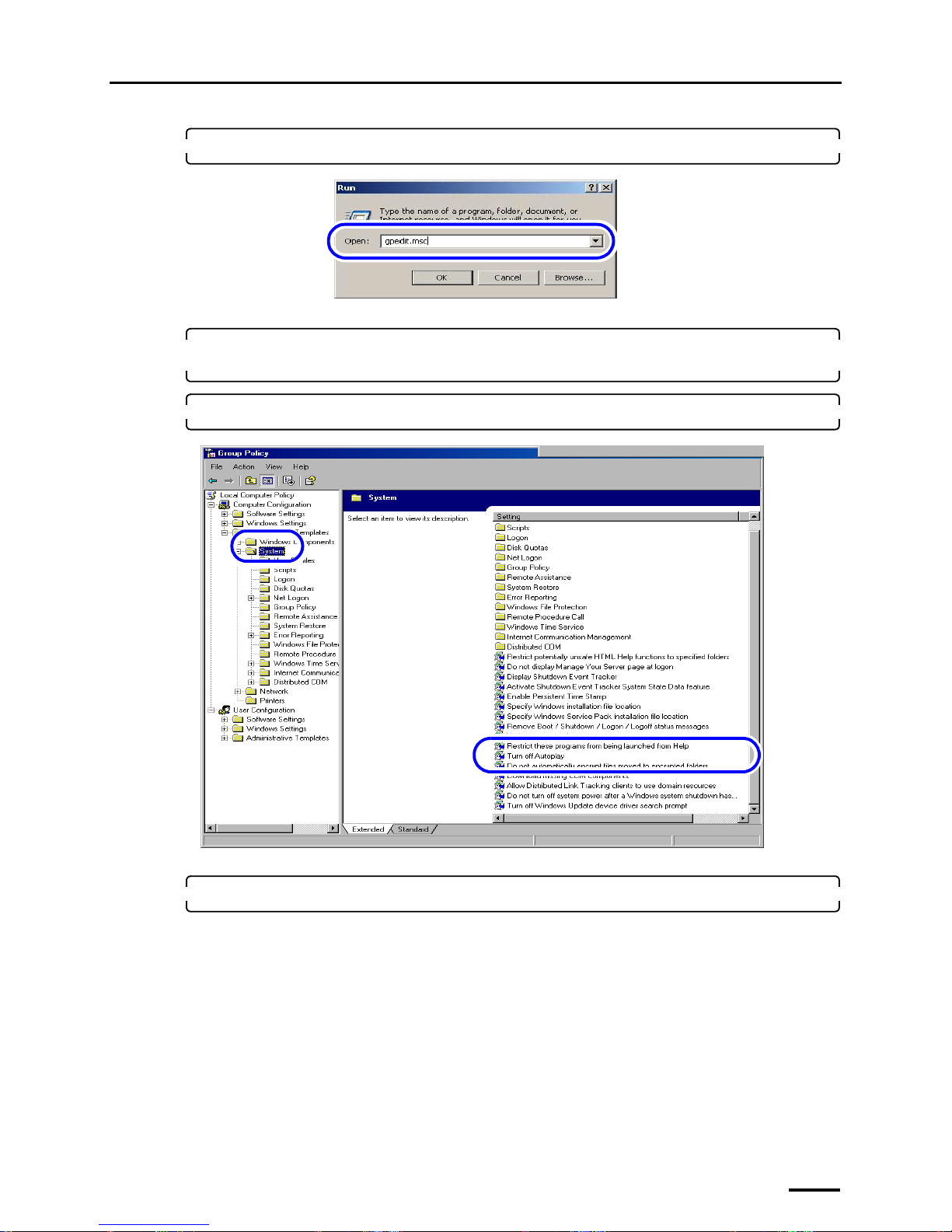
2. Input gpedit.msc and click OK.
The Group Policy display is shown.
3. Select Computer Configuration→ Administrative Templates→System in the left of the
Group Policy display.
4. Double-click Turn off Autoplay.
The Turn off Autoplay Properties display is shown.
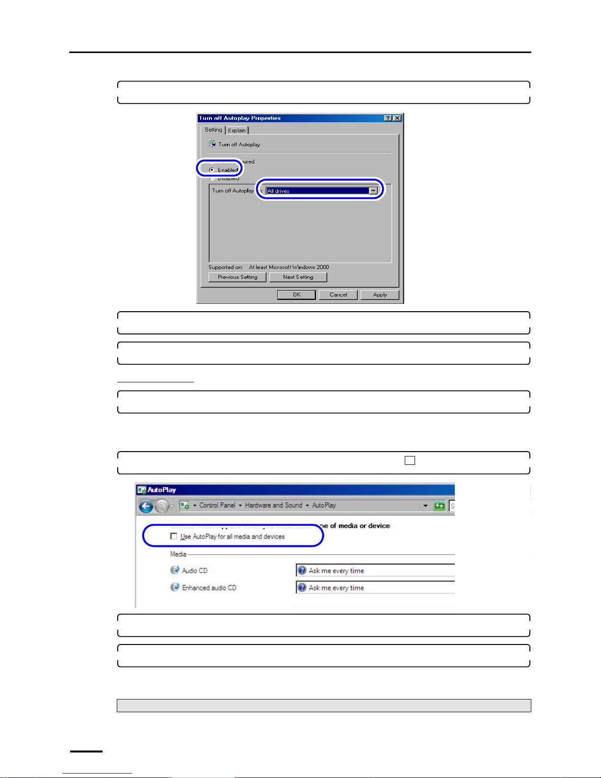
5. Select Enabled.
S088716
S088717
Page 30
4 Setting up the PC
22
6. Select All drives.
7. Click OK.
8. Click the close button in the upper-right corner of the Group Policy display to close it.
For Windows Vista
1. Access the AutoPlay display.
Bringing up the display
Start → Control Panel → Hardware and Sound → AutoPlay
2. Clear the Use AutoPlay for all media and devices check box ( ).
3. Click Save.
4. Click the Close button at the upper right of the AutoPlay display to close it.
This completes turning off autoplay of the media drive.
Next, go to ☞4.5 Setting the taskbar.
S088718
S091805
Page 31
4 Setting up the PC
23
4.5 Setting the taskbar
The display slightly varies depending on the operating system, but the procedure is the same.
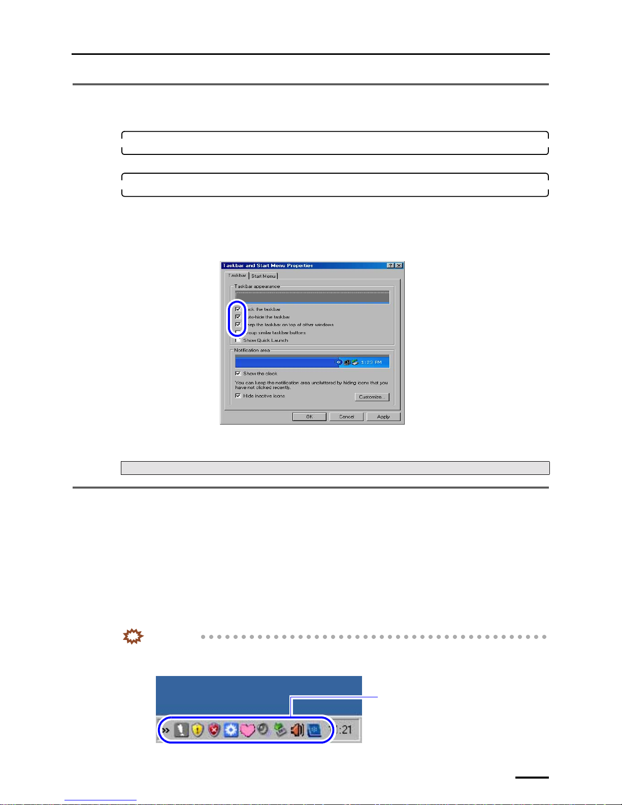
1. Right-click the taskbar in the lower of the screen and select Properties.
The Taskbar and Start Menu Properties display is shown.
2. Select the check boxes of the items below, and click OK.
• Lock the taskbar
• Auto-hide the taskbar
• Keep the taskbar on top of other windows
It is not necessary to specify other items.
This completes setting of the taskbar.
4.6 Turning off the hotkey function (shortcut key function) on the
resident application
If there are hotkey functions (shortcut key functions) in the resident application (icon shown in the right of taskbar), turning
off the function is required.
Hotkey (shortcut key) is a function to operate the frequently-used function with the key operation of keyboard instead of
clicking the function on the display.
If the hotkey function (shortcut key function) of the resident application is on, the shortcut key function settings configured
on the EZ Controller may not be used.
Confirm the resident application setting, turn off the function if there is a mode for switching the hotkey function (shortcut
key function) on or off. If there is no mode for switching the hotkey function (shortcut key function), there is no need to
configure.
IMPORTANT
• Releasing the resident is not required.
Example:
Next, go to ☞4.6 Turning off the hotkey function (shortcut key function) on the resident application.
S088719
Resident application
G088722
Page 32
4 Setting up the PC
24
4.7 Configuring the User Account Control setting
This operation is necessary only for Windows Vista.
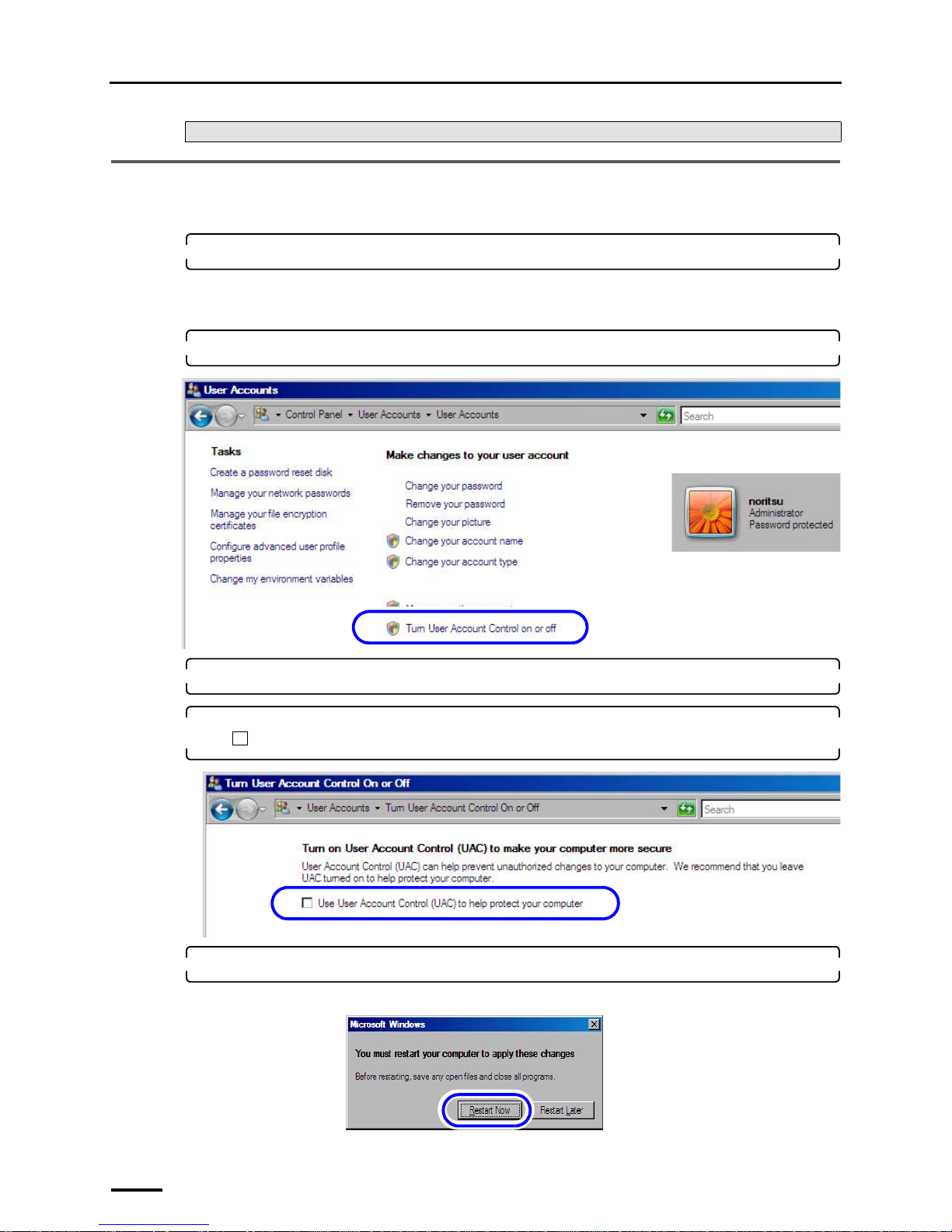
1. Access the User Accounts display.
Bringing up the display
Start → Control Panel → User Accounts → User Accounts
2. Click Turn User Account Control on or off.
3. If the User Account Control display is shown, click Continue.
4. Clear the Use User Account Control (UAC) to help protect your computer check box
().
5. Click OK.
If the following display is shown, click Restart Now.
Next, go to ☞4.7 Configuring the User Account Control setting.
S091806
S091807
S091808
Page 33
4 Setting up the PC
25
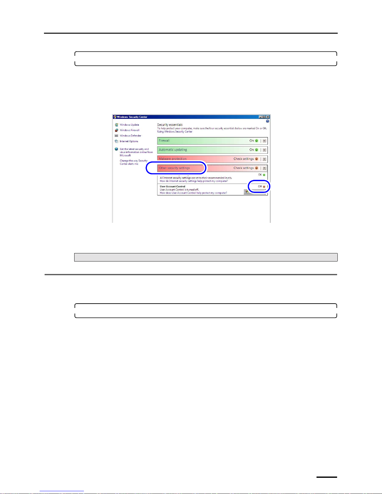
6. Check whether User Account is invalidated.
(1) Access the Windows Security Center.
Bringing up the display
Start → Control Panel → Security → Security Center
(2) Click Other security settings and confirm that User Account Control is set to Off.
(3) Click the Close button at the upper right of the Windows Security Center display to close it.
(4) Click the Close button at the upper right of the Security display to close it.
This completes the User Account Control settings.
4.8 Configuring Sidebar settings
This operation is necessary only for Windows Vista.
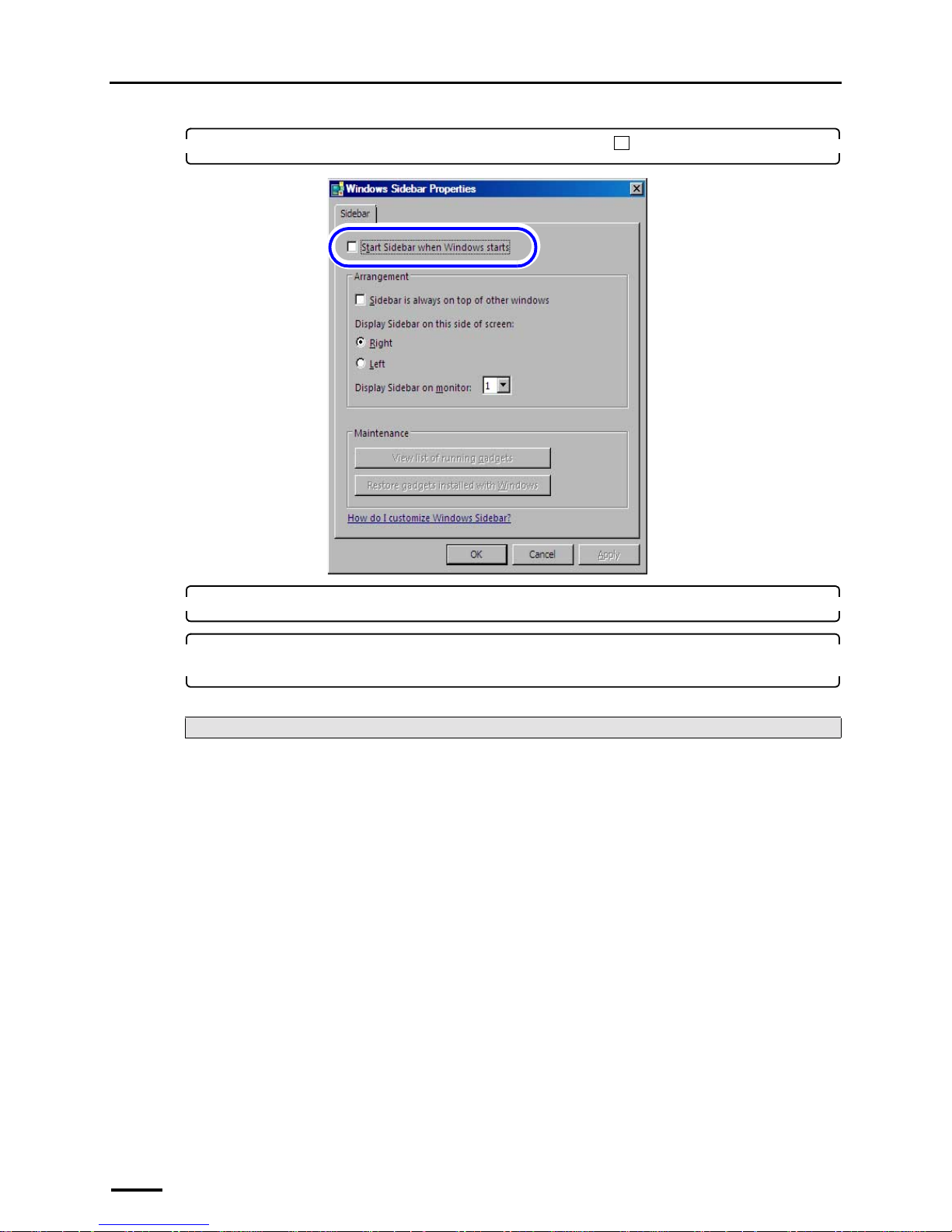
1. Access the Windows Sidebar Properties display.
Bringing up the display
Start → Control Panel → Appearance and Personalization → Windows Sidebar Properties
Next, go to ☞4.8 Configuring Sidebar settings.
S091809
Page 34
4 Setting up the PC
26
2. Clear the Start Sidebar when Windows starts check box ( ).
3. Click OK.
4. Click the Close button at the upper right of the Appearance and Personalization display to
close it.
This completes the Sidebar settings.
Next, go to ☞5 Installing the TWAIN driver.
S091810
Page 35
5 Installing the TWAIN driver
27
5 Installing the TWAIN driver
If there is an administrator on the network, ask him/her before installing.
This operation is not necessary if the Controller is installed on the PC.
The following software are installed by installing the TWAIN driver.
• Windows Installer 3.1
*1
• Microsoft Visual C++ 2005 Redistributable
• Microsoft .NET Framework Version 3.0
*1
• PostgreSQL8.1
• MSXML 4.0 SP2 Parser and SDK
• MSXML 6.0 Parser
*1
• Sentinel Protection Installer 7.3.0
• EZ Controller
• EZ Controller ImgDataProc Additional Software
• System Capture
*1. Not installed for Windows Vista.
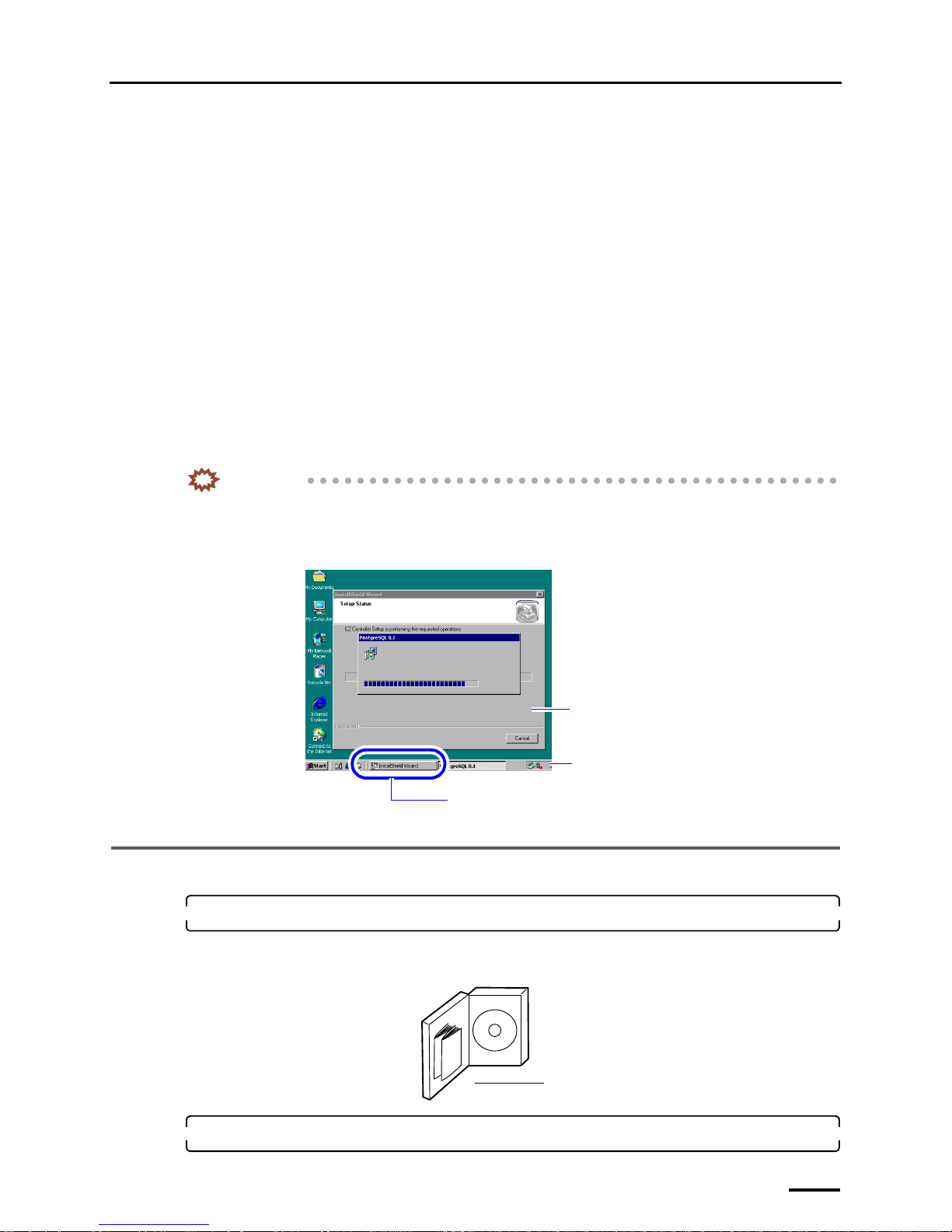
IMPORTANT
• A screen newly displayed may not come to the front while the software is installed (when the screen is
switched). In this case, click the blinking button of the screen on the taskbar. Then, the screen comes to the
front. Continuously install the software with the following procedure.
Example:
5.1 Installation procedure
1. Prepare the following CD.
• TWAIN driver CD
TWAIN driver is shown on the label.
2. Insert the TWAIN driver CD-ROM.
Screen newly displayed (at the back)
Button of the screen newly displayed (Blinking)
Taskbar
S088428
TWAIN driver CD
G085386
Page 36
5 Installing the TWAIN driver
28
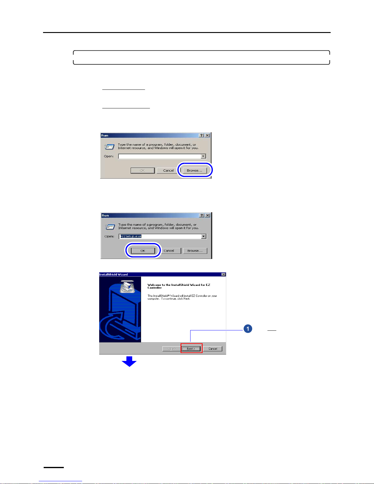
3. Run the installer.
(1) Access the Run display.
For Windows XP
Select Start → Run.
For Windows Vista
Select Start → All Programs → Accessories → Run.
(2) Click Browse.
The Browse display is shown.
(3) Select the drive to which the CD-ROM was inserted →Setup.exe, and click Open.
(4) Click OK.
The installer starts and the InstallShield Wizard display is shown.
The display slightly varies depending on the
operating system, but the procedure is the same.
S082377
The display slightly varies depending on the
operating system, but the procedure is the same.
S088113
Click Next.
S087698
Page 37
5 Installing the TWAIN driver
29
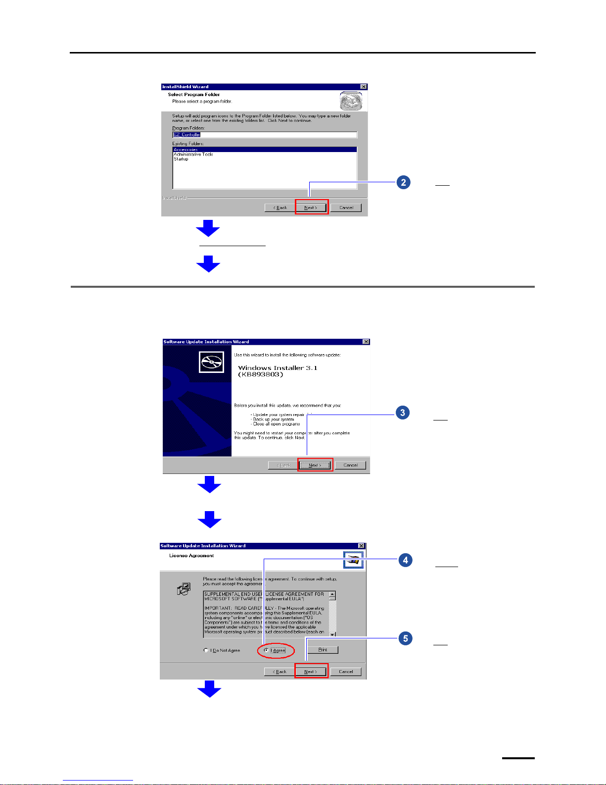
5.2 Installing the Windows Installer 3.1
If the installation display for Windows Installer 3.1 is not shown, go to ☞5.3 Installing the Microsoft Visual C++ 2005
SP1 Redistributable.
Click Next without selecting any
option.
Next, install Windows Installer 3.1.
S087699
Click Next.
Terms of use is shown.
S087700
Select I Agree.
Click Next.
S087701
Page 38
5 Installing the TWAIN driver
30
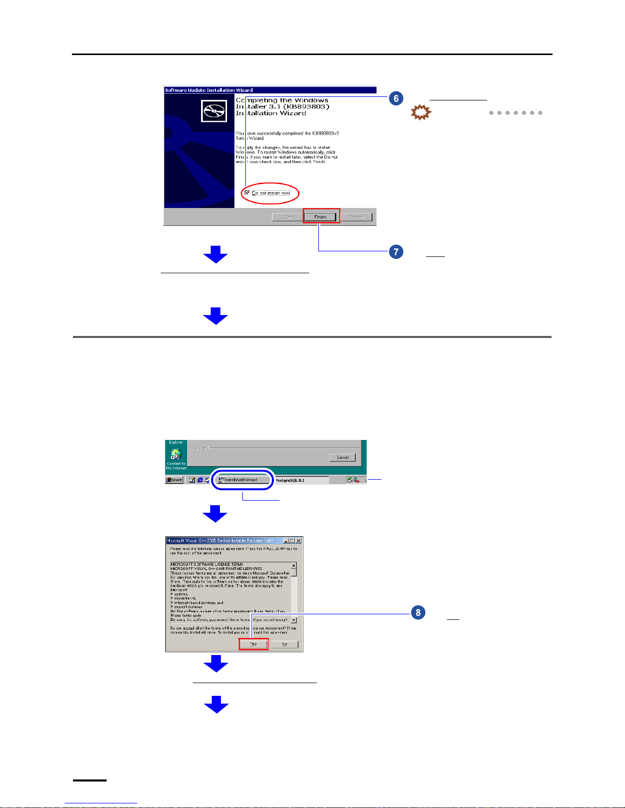
5.3 Installing the Microsoft Visual C++ 2005 SP1 Redistributable
If the installation display for the Microsoft Visual C++ 2005 SP1 Redistributable is not shown, go to ☞5.4 Installing the
Microsoft .NET Framework Version 3.0.
Select Do not restart now.
IMPORTANT
• The installation is continued even if
you do not select it. However, be
sure to select it otherwise the
restarting performed at the end of
the installation may take several
minutes.
Click Finish.
Next, install Microsoft Visual C++ 2005 SP1 Redistributable
.
Terms of use is shown.
S087702
If the display does not change to the following installation display, click the button of the screen newly displayed on the taskbar. The
screen newly displayed comes to the front.
Button of the screen newly displayed
Taskbar
Example:
S088428
Click Yes.
Next, install the Microsoft .NET Framework Version 3.0.
S087703
Page 39
5 Installing the TWAIN driver
31
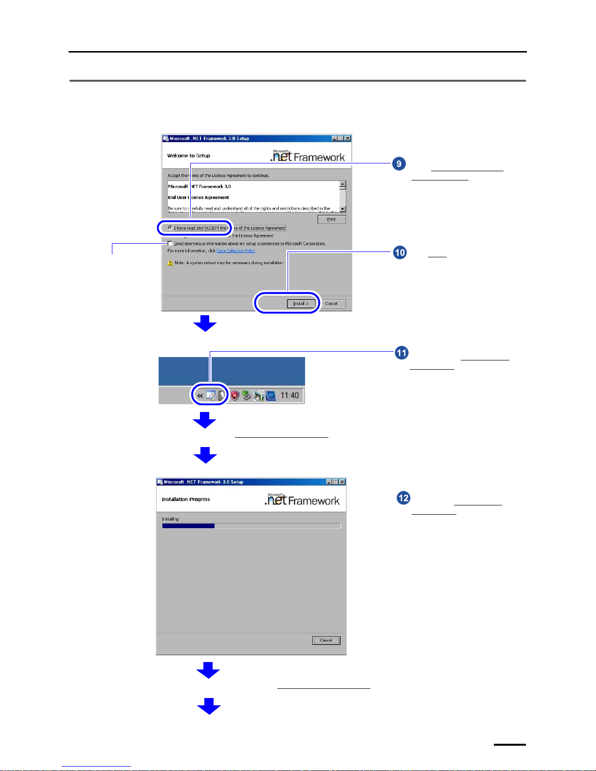
5.4 Installing the Microsoft .NET Framework Version 3.0
If the installation display for the Microsoft .NET Framework Version 3.0 is not shown, go to ☞5.5 Installing the
PostgreSQL8.1.
You do not need to
select this check
box.
Select I accept the terms of the
License Agreement.
Click Install
.
S091227
Double-click the Microsoft .NET
Framework 3.0 icon on the taskbar at
the lower right of the screen.
The confirmation display of Microsoft .NET Framework 3.0 installation status is shown.
G091230
Wait until the Microsoft .NET
Framework 3.0 installation is
finished.
The completion screen is shown after the Microsoft .NET Framework 3.0 installation is finished.
S091228
Page 40
5 Installing the TWAIN driver
32
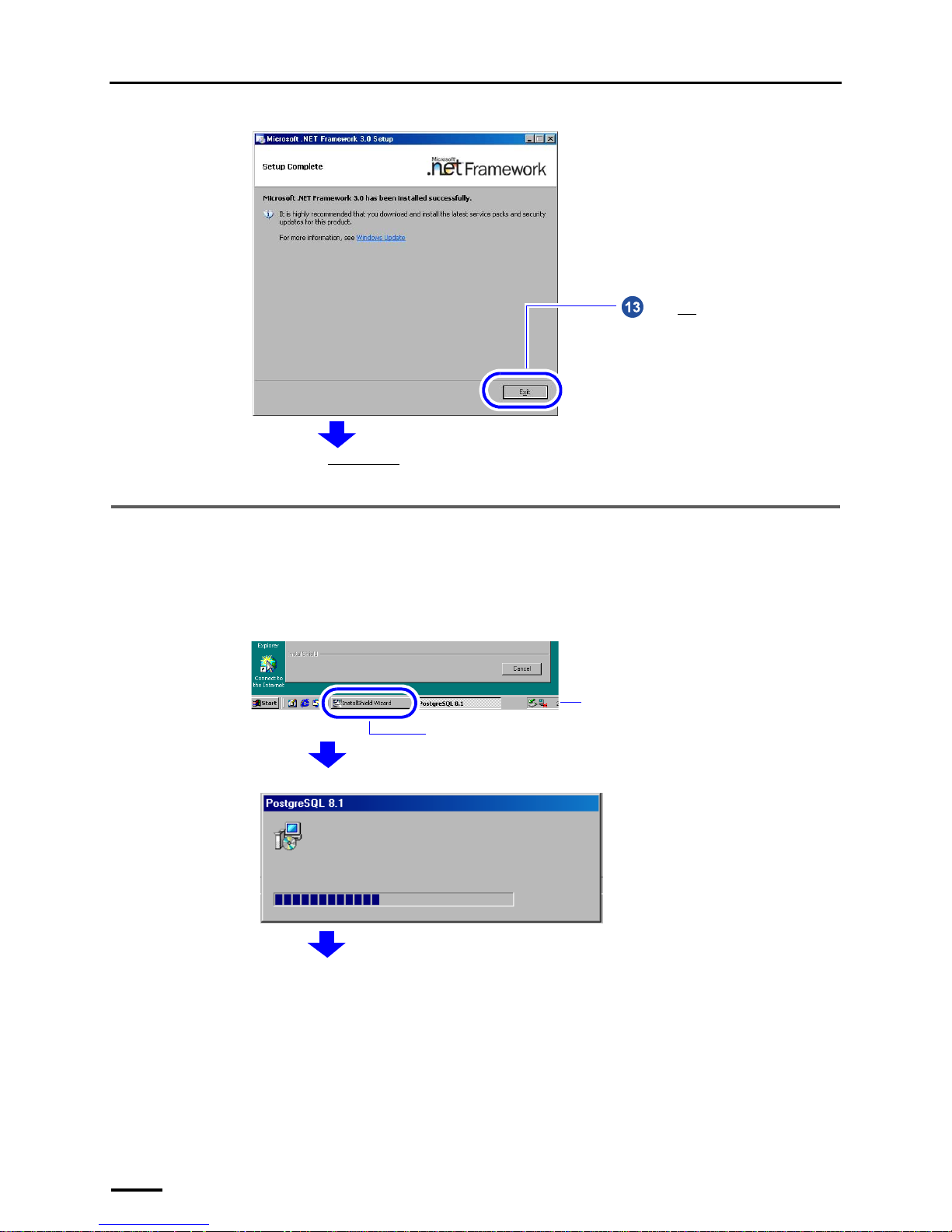
5.5 Installing the PostgreSQL8.1
If the installation display for the PostgreSQL8.1 is not shown, go to ☞5.6 Installing the MSXML 4.0 SP2 Parser and SDK.
Click End.
Next, install the PostgreSQL8.1.
S091229
If the display does not change to the following installation display, click the button of the screen newly displayed on the taskbar. The
screen newly displayed comes to the front.
Button of the screen newly displayed
Taskbar
Example:
S088428
S089348
Page 41
5 Installing the TWAIN driver
33
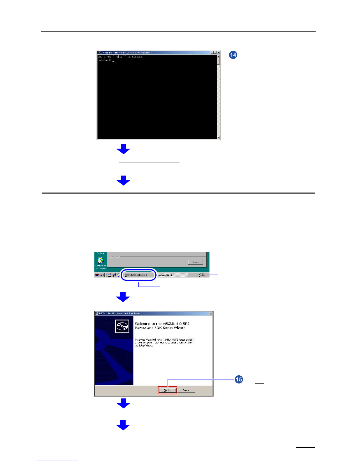
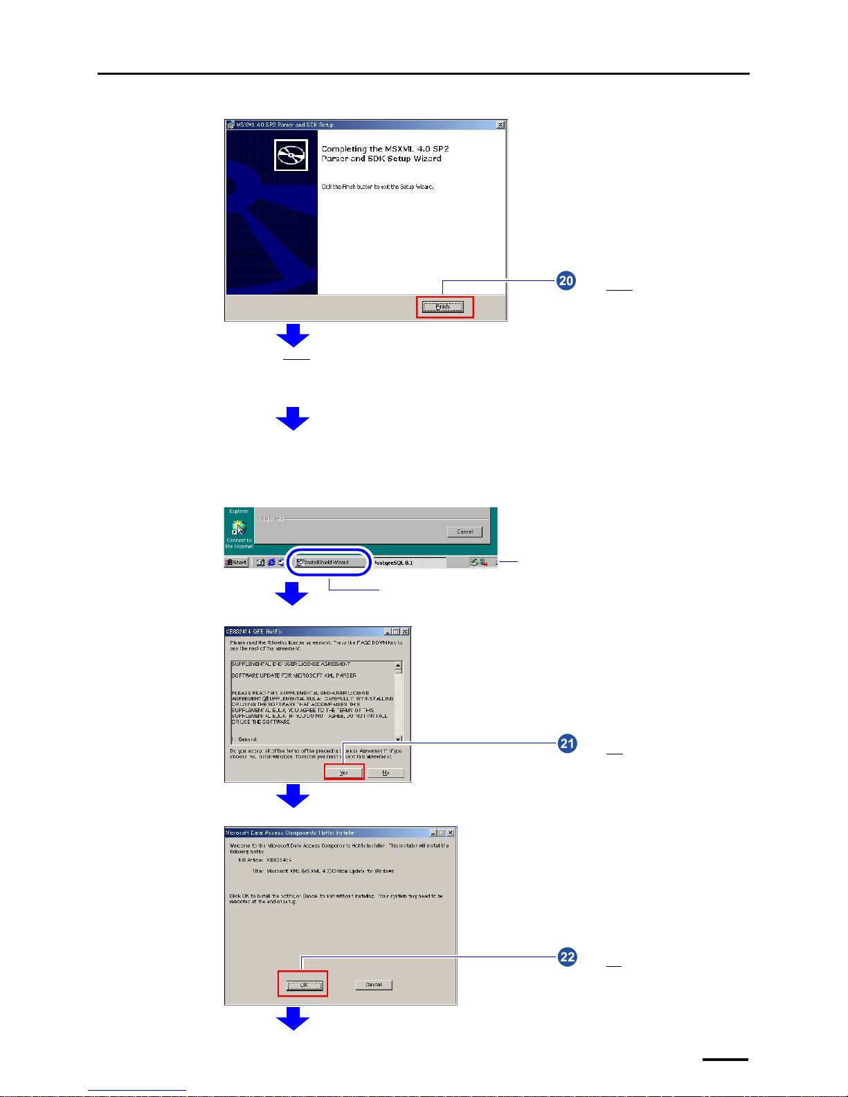
5.6 Installing the MSXML 4.0 SP2 Parser and SDK
If the installation display for the MSXML 4.0 SP2 Parser and SDK is not shown, go to ☞5.7 Installing the MSXML 6.0
Parser.
Next, install the MSXML 4.0 SP2 Parser and SDK.
Wait for a while until the display is
closed.
G087707
If the display does not change to the following installation display, click the button of the screen newly displayed on the taskbar. The
screen newly displayed comes to the front.
Button of the screen newly displayed
Taskbar
Example:
S088428
Click Next.
Terms of use is shown.
S087708
Page 42
5 Installing the TWAIN driver
34
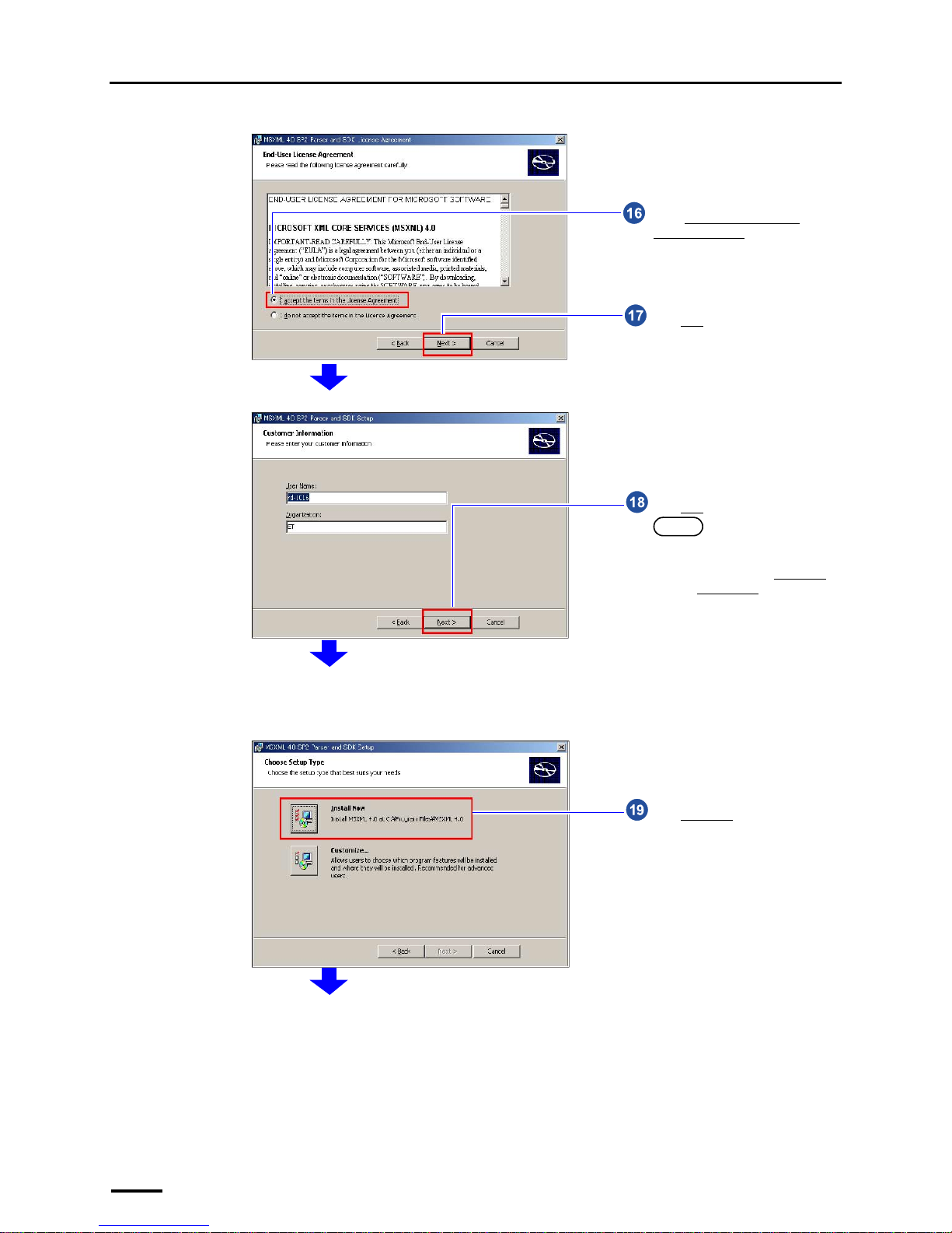
Click Next.
Select I accept the terms in the
License Agreement.
S087709
Click Next.
NOTE
• Information such as the name of
the PC on which the software is
installed is shown in User Name
and Organization
. You do not
need to change those.
S087710
Click Install now.
S087711
Page 43
5 Installing the TWAIN driver
35
Click Finish.
Next, install the Hotfix.
For Windows Vista, go to
☞5.8 Installing the Sentinel Protection Installer 7.3.0.
Terms of use is shown.
S087712
If the display does not change to the following installation display, click the button of the screen newly displayed on the taskbar. The
screen newly displayed comes to the front.
Button of the screen newly displayed
Taskbar
Example:
S088428
Click Yes.
S087713
Click OK.
S087714
Page 44
5 Installing the TWAIN driver
36
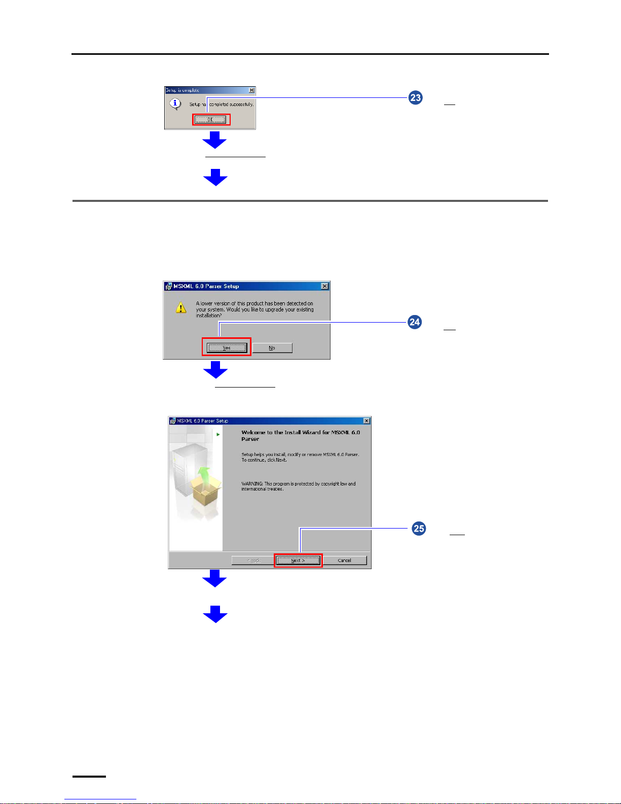
5.7 Installing the MSXML 6.0 Parser
If the installation display for the MSXML 6.0 Parser is not shown, go to ☞5.8 Installing the Sentinel Protection Installer
7.3.0.
Click OK.
Next, install the MSXML 6.0 Parser.
S087715
Installation of the MSXML 6.0 Parser starts.
Click Yes.
Go to the next step if the following display is not shown.
S091139
Click Next.
Terms of use is shown.
S088694
Page 45
5 Installing the TWAIN driver
37
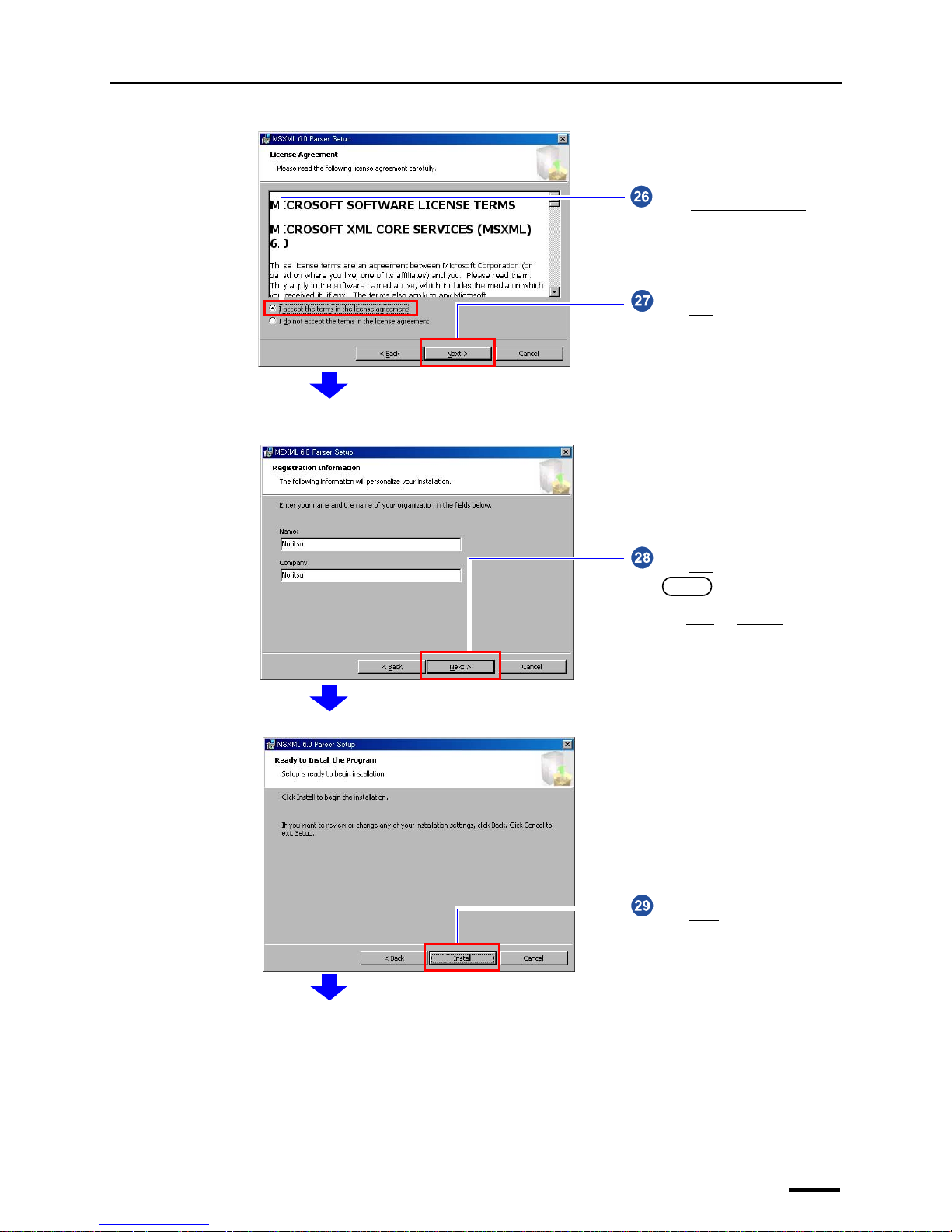
Click Next.
Select I accept the terms in the
license agreement.
S088695
Click Next.
NOTE
• You do not need to change the
Name
and Company.
Example:
S088696
Click Install.
S088697
Page 46
5 Installing the TWAIN driver
38
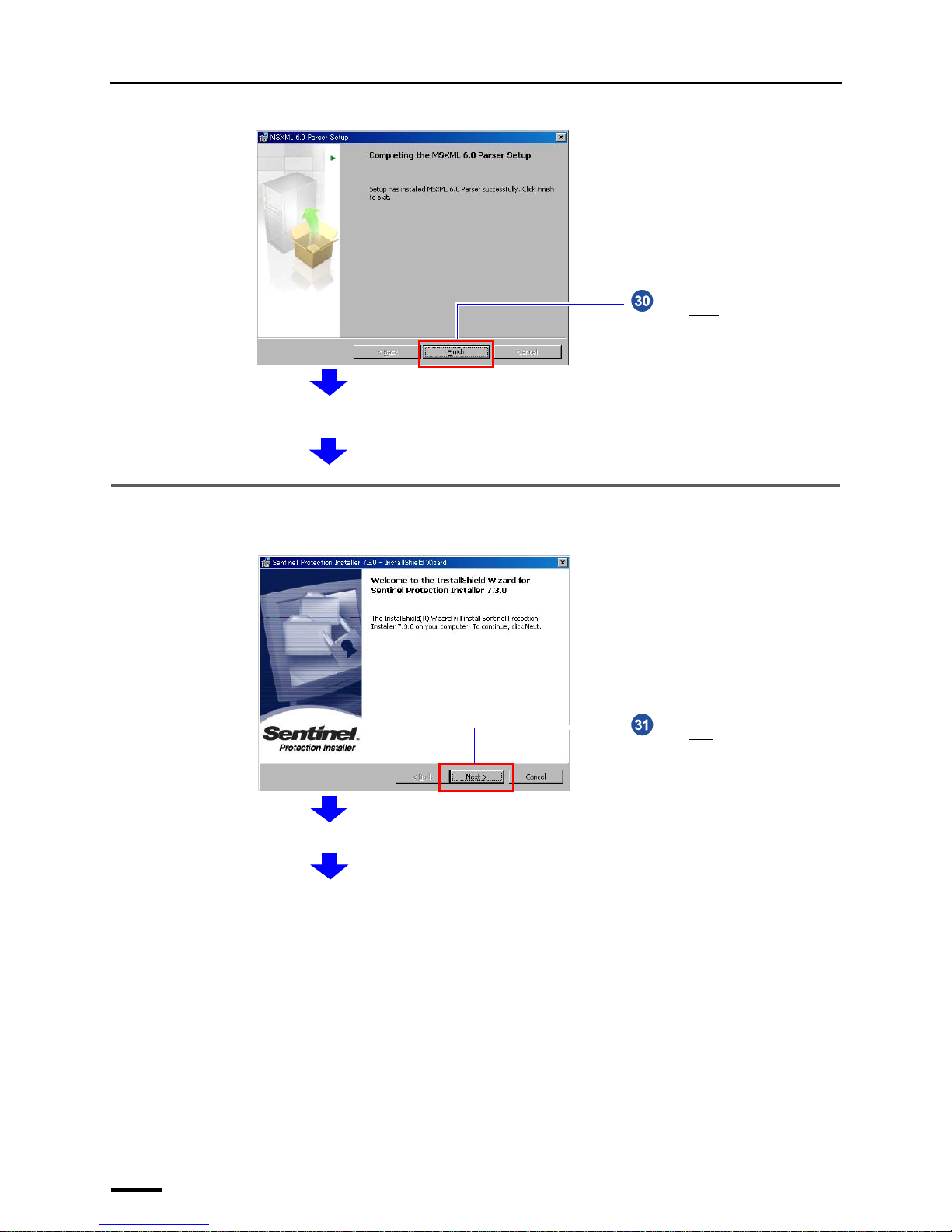
5.8 Installing the Sentinel Protection Installer 7.3.0
If the installation display for the Sentinel Protection Installer 7.3.0 is not shown, go to ☞5.9 Installing the EZ Controller.
Click Finish.
Next, install the Sentinel Protection Installer 7.3.0.
S088698
Click Next.
Terms of use is shown.
S088641
Page 47
5 Installing the TWAIN driver
39
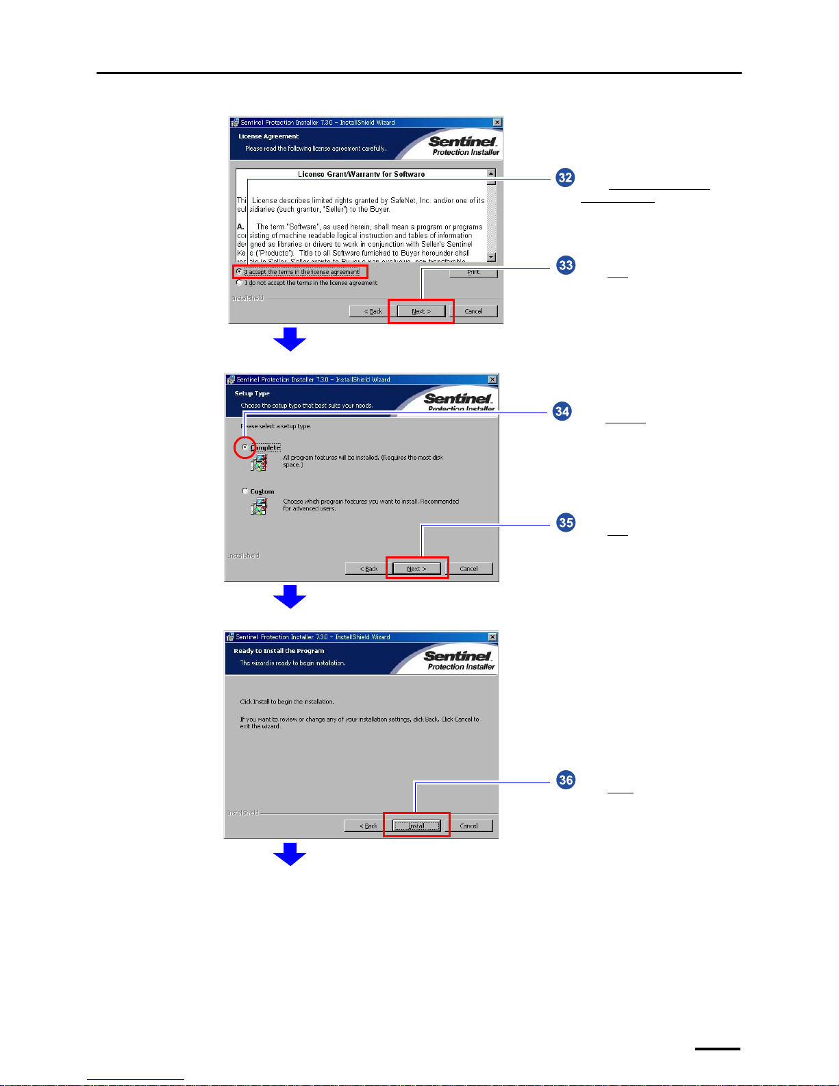
Click Next.
Select I accept the terms in the
license agreement.
S088642
Click Next.
Select Complete.
S088643
Click Install.
S088644
Page 48
5 Installing the TWAIN driver
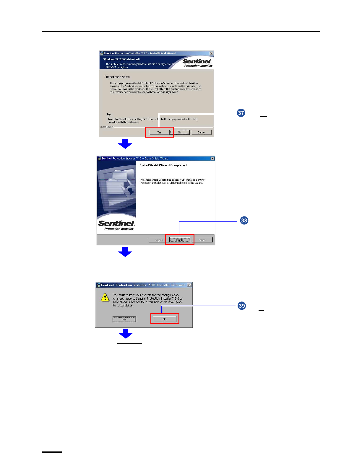
40
Click Yes.
S088739
Click Finish.
S088646
Installing the EZ Controller starts.
Click No.
This display may not be shown depending on the setting. Go to the next step if the following display is not shown.
S088631
Page 49
5 Installing the TWAIN driver
41
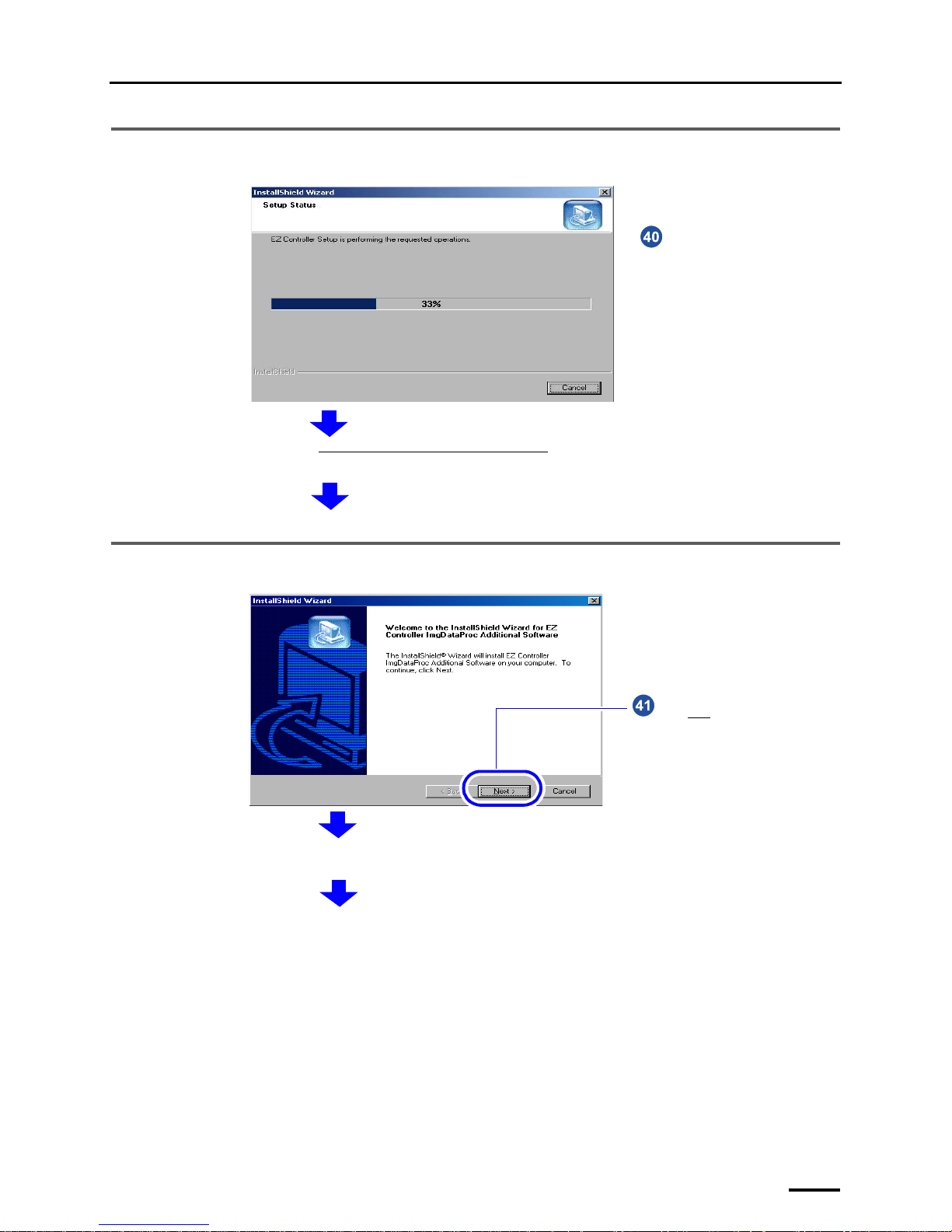
5.9 Installing the EZ Controller
5.10 Installing the EZ Controller ImgDataProc Additional Software
Wait for seconds until the
installation is completed.
Next, install the EZ Controller ImgDataProc Additional Software.
S088703
Click Next.
The confirmation display of License Agreement is shown.
S091231
Page 50
5 Installing the TWAIN driver
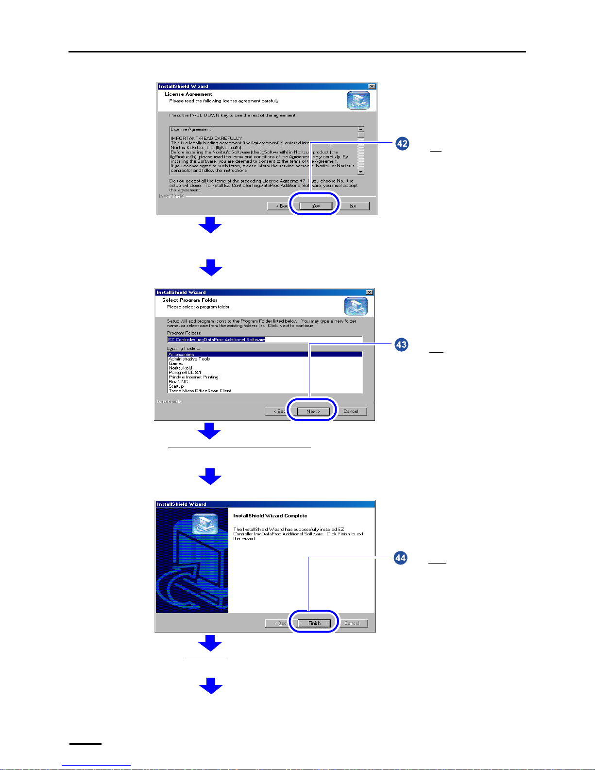
42
Click Yes.
The confirmation display of the location to save the program is shown.
S091232
Click Next without selecting any
option.
The EZ Controller ImgDataProc Additional Software installation starts. The completion screen is shown after the installation
is finished.
S091233
Click Finish.
Next, the SystemCapture installation screen is shown.
S091234
Page 51
5 Installing the TWAIN driver
43
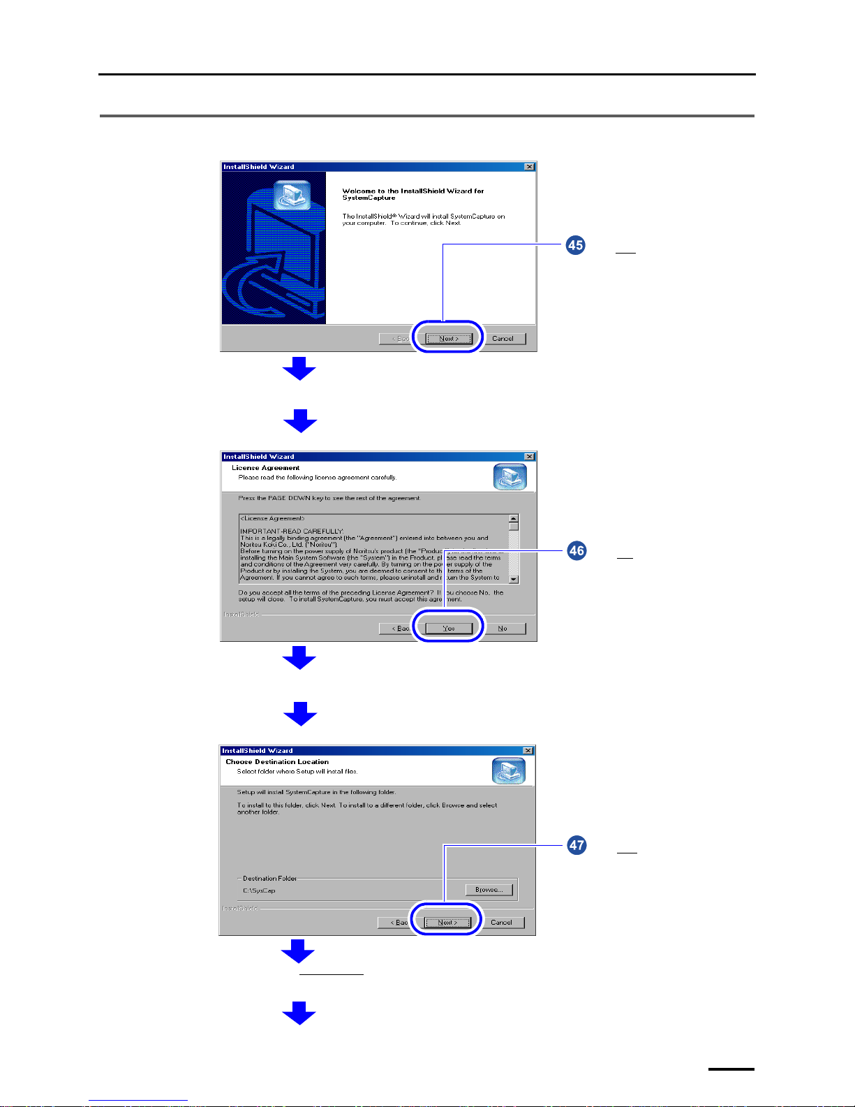
5.11 Installing the System Capture
Click Next.
The confirmation display of License Agreement is shown.
S091235
Click Yes.
The confirmation display of the location to save the program is shown.
S091236
Click Next without changing the
settings.
The installation of SystemCapture starts. The completion screen is shown after the installation is finished.
S091237
Page 52
5 Installing the TWAIN driver
44
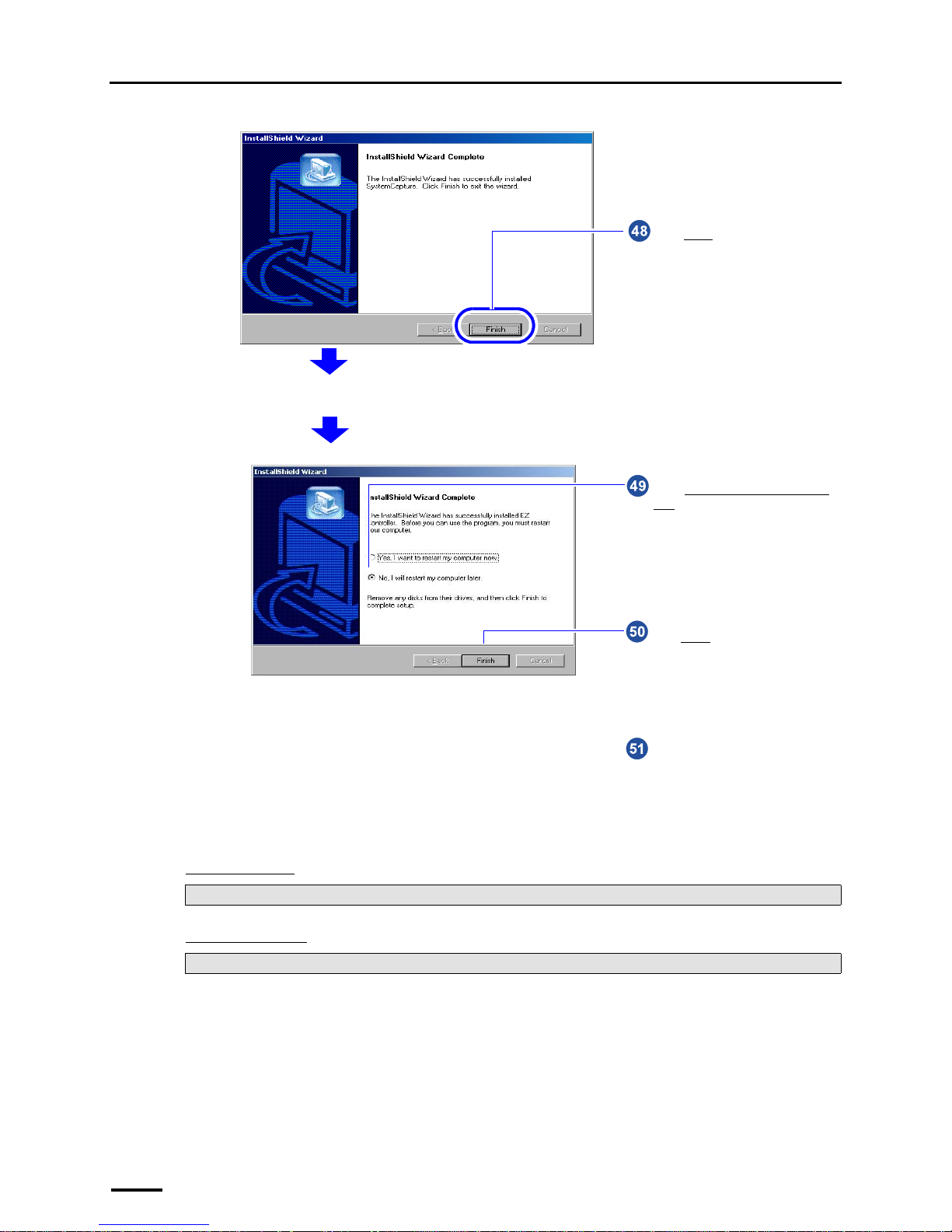
This completes installing the TWAIN driver.
"
""
" Next, go to • • •
For Windows XP
For Windows Vista
Perform ☞6 Installing the SYSTEM PROGRAM.
Perform ☞7.1 Connecting the power supply.
Click Finish.
The completion screen is shown after the installation is finished.
S091238
Click Finish.
Select No, I will restart my computer
later.
Remove the CD-ROM.
S087716
Page 53
6 Installing the SYSTEM PROGRAM
45
6 Installing the SYSTEM PROGRAM
If there is an administrator on the network, ask him/her before installing.
IMPORTANT
• If connecting the scanner to the PC on which the controller is installed, exit the controller application after
restarting the PC.
Bringing up the display
Click F on the Controller Main Display. → Click Quit The Application.
Installation procedure
1. Prepare the following CD.
• LS-# # # # SYSTEM PROGRAM CD
*1
LS-# # # # SYSTEM PROGRAM
*1
is printed on the label.
*1. The model name is shown in # # # #.
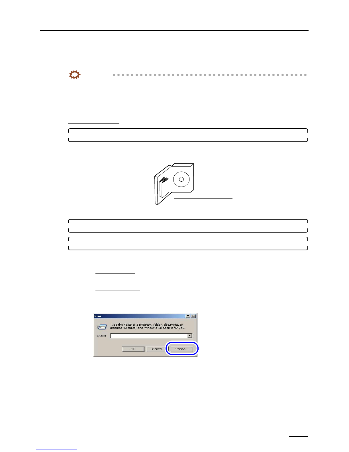
2. Insert the SYSTEM PROGRAM CD-ROM.
3. Run the installer.
(1) Access the Run display.
For Windows XP
Select Start → Run.
For Windows Vista
Select Start → All Programs → Accessories → Run.
(2) Click Browse.
The Browse display is shown.
(3) Select the drive to which the CD-ROM was inserted →Setup.exe, and click Open.
LS-# # # # SYSTEM PROGRAM CD
*1
G085386
The display slightly varies depending on the
operating system, but the procedure is the same.
S082377
Page 54
6 Installing the SYSTEM PROGRAM
46
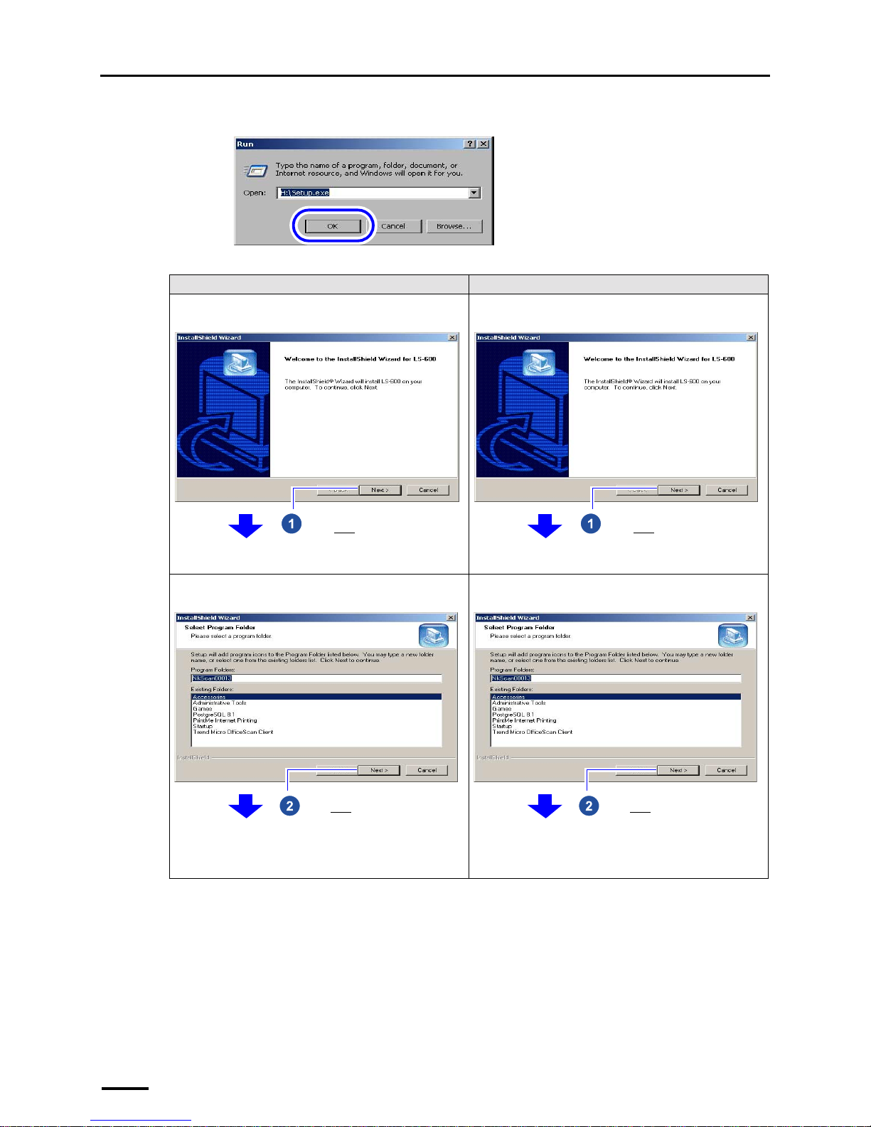
(4) Click OK.
The installer starts and the InstallShield Wizard display is shown.
For Windows XP For Windows Vista
Example: If LS-600 SYSTEM PROGRAM was
installed
Example: If LS-600 SYSTEM PROGRAM was
installed
Example: If LS-600 SYSTEM PROGRAM was
installed
Example: If LS-600 SYSTEM PROGRAM was
installed
The display slightly varies depending on the
operating system, but the procedure is the same.
S088113
Click Next. Click Next.
Click Next without changing the
setting.
→ Installation starts.
Click Next without changing the
setting.
→ Installation starts.
Page 55
6 Installing the SYSTEM PROGRAM
47
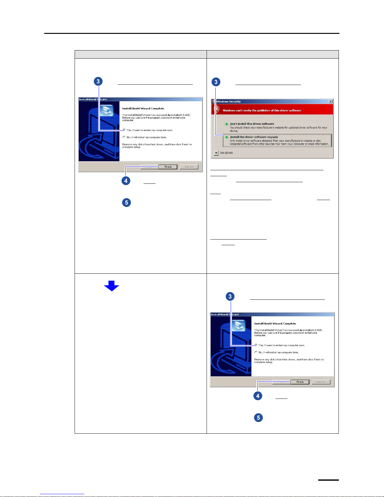
This completes installing the SYSTEM PROGRAM.
Example: If LS-600 SYSTEM PROGRAM was
installed
Example: If LS-600 SYSTEM PROGRAM was
installed
Example: If LS-600 SYSTEM PROGRAM was
installed
For Windows XP For Windows Vista
Click Finish.
Select Yes, I want to restart my computer now
.
Remove the CD-ROM.
Select Install this driver software anyway.
If the scanner power cord and USB cable are not connected
correctly
The message Connect the device. - USB Scanner is shown.
Reconnect the scanner power cord and USB cable and click
Retry
.
When the Found New Hardware
display is shown, click Cancel.
If the message is shown again
Click Cancel and install the SYSTEM PROGRAM again.
Click Finish.
Select Yes, I want to restart my computer now
.
Remove the CD-ROM.
Page 56
6 Installing the SYSTEM PROGRAM
48
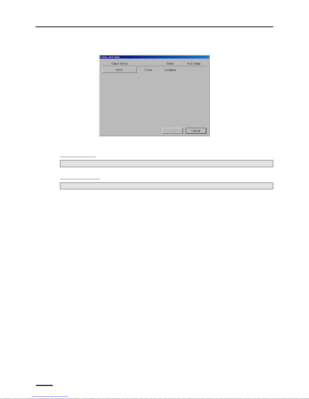
If connecting the scanner to the PC on which the controller is installed, the Startup check menu display is shown.
Go to the next step while the Startup check menu display is shown.
"
""
" Next, go to • • •
For Windows XP
For Windows Vista
Perform ☞7 Connecting the power supply and setting the USB driver.
Perform Step 3 in ☞7.2 Configuring USB driver settings.
S089245
Page 57
7 Connecting the power supply and setting the USB driver
49
7 Connecting the power supply and setting the USB
driver
7.1 Connecting the power supply
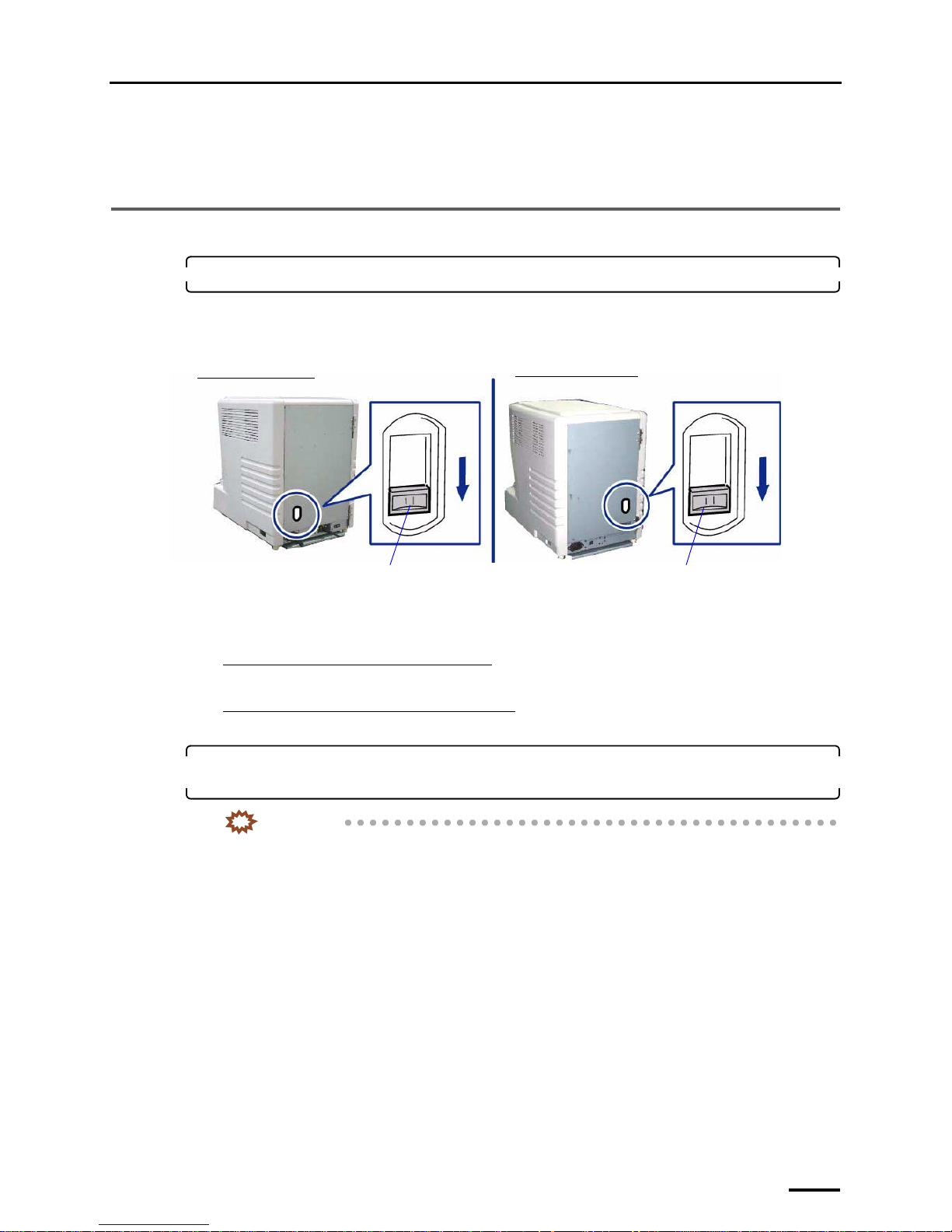
1. Confirm that the transfer switch is set to downside.
Before shipment, it is set to the downside.
If not, set the transfer switch to the downside with a slotted blade screwdriver.
Example: Transfer switch that is set to the downside
The transfer switch is used for selecting whether to supply power from household socket or from the connected
printer to this product.
If supplying power from household socket
Set the transfer switch to the downside.
If supplying power from the connected printer
Set the transfer switch to the upside.
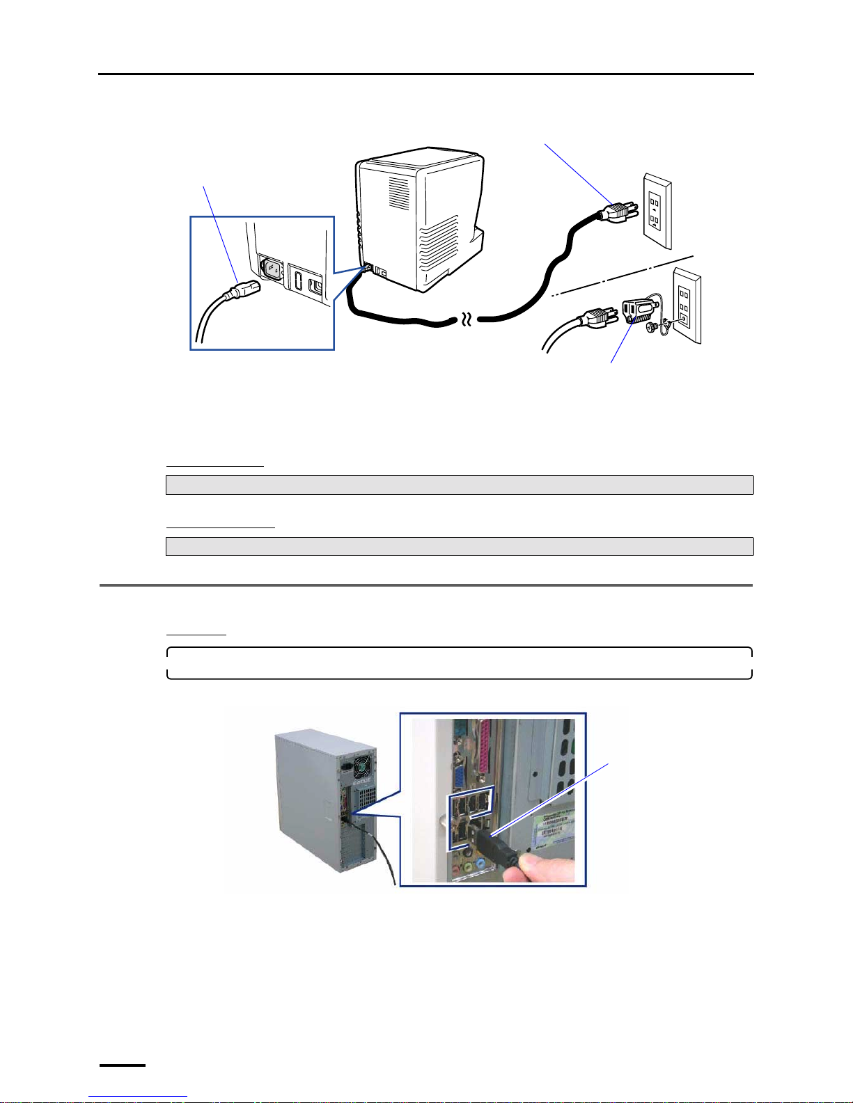
2. Connect the supplied power cord to the scanner, and put the plug into the outlet of the main
power supply.
IMPORTANT
• Use an outlet with ground terminal for the power cord to ground the wire.
• If grounding adapter is used, ground the ground wire from the grounding adapter.
Transfer switch
Transfer switch
Back view of the LS-600
Back view of the LS-1100
G088491
Page 58
7 Connecting the power supply and setting the USB driver
50
Example:
This completes connecting the power supply.
"
""
" Next, go to • • •
For Windows XP
For Windows Vista
7.2 Configuring USB driver settings
Procedure
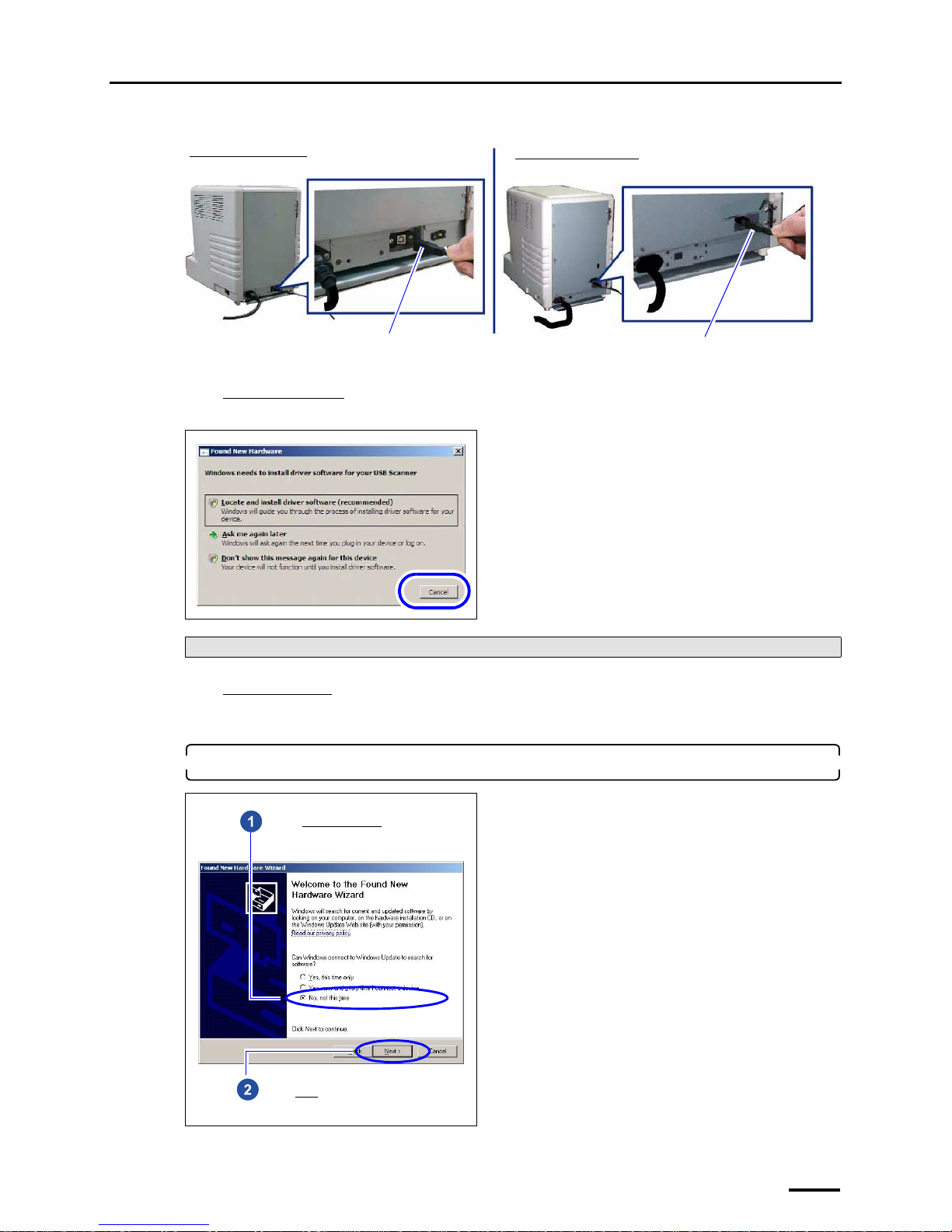
1. Connect the scanner to the PC with the supplied USB cable.
PC side
Perform ☞7.2 Configuring USB driver settings.
Perform only Step 1 in ☞7.2 Configuring USB driver settings.
Power cord
Plug
Grounding adapter (prepared by the
user)
G087642
USB cable
You can connect the USB
cable to any USB port.
G087643
Page 59
7 Connecting the power supply and setting the USB driver
51
Scanner side
For Windows Vista
When the following display is shown, click Cancel.
For Windows XP
The display to install the USB driver is shown.
Go to Step 2.
2. Install the USB driver.
Next, go to ☞6 Installing the SYSTEM PROGRAM.
USB cable
USB cable
Back view of the LS-600
Back view of the LS-1100
G088603
Select No, not this time.
Click Next.
Page 60
7 Connecting the power supply and setting the USB driver
52
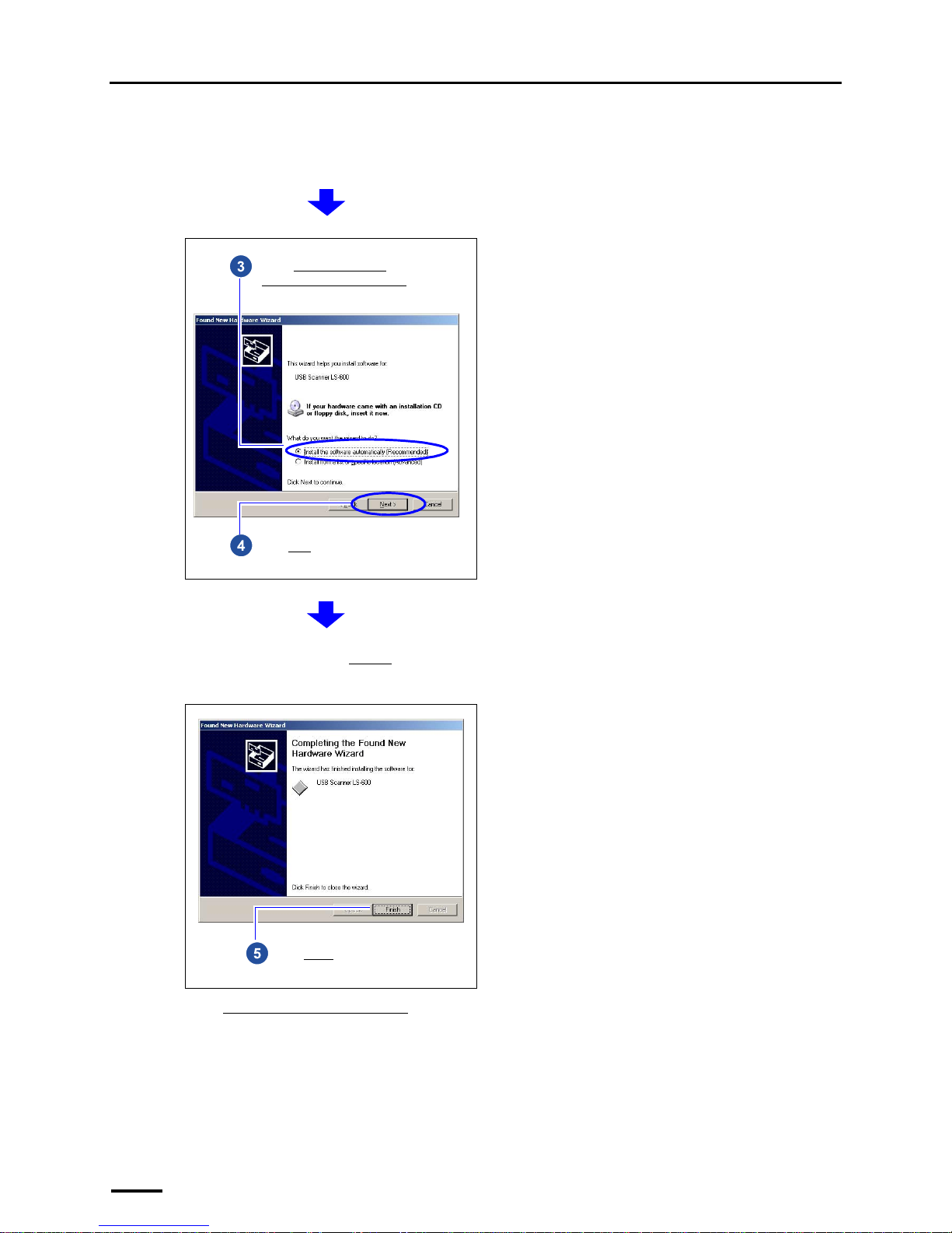
If the display below is shown
The installation failed. The USB cable may be connected before installing the TWAIN driver or SYSTEM
PROGRAM. The USB scanner cannot be recognized, uninstall the software.
• Perform the operations from Step 2 to Step 6 in ☞10.2 If connecting the USB cable and starting the PC before
installing the scanner software.
This display may not be shown depending on the setting. Go to the next step if this display is not shown.
Select Install the software
automatically (Recommended).
Click Next.
If an alert message is shown, click Continue.
Installation automatically starts.
Click Finish.
Page 61
7 Connecting the power supply and setting the USB driver
53
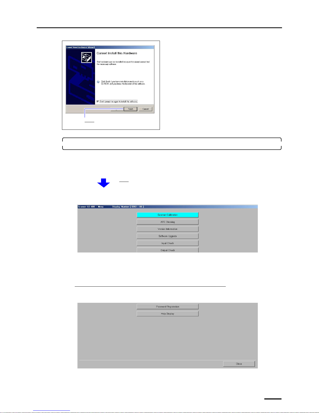
3. Check whether each software was normally installed.
Access the Menu display.
Bringing up the display
On the Windows desktop display, click Start. → All Programs → Click LS-600 or LS-1100.
Example: Menu display
If the Menu display is shown, the installation was normally performed.
If the Menu display is not shown, the installation failed.
Follow the instructions explained in ☞10.1 If installing TWAIN driver or SYSTEM PROGRAM failed.
If connecting the scanner to the PC on which the controller is installed
Click Close to close the Menu display.
Example: Menu display
Click Finish.
The Menu display is shown.
S5202-00-UM02
S5202-00-UM02
Page 62
7 Connecting the power supply and setting the USB driver
54
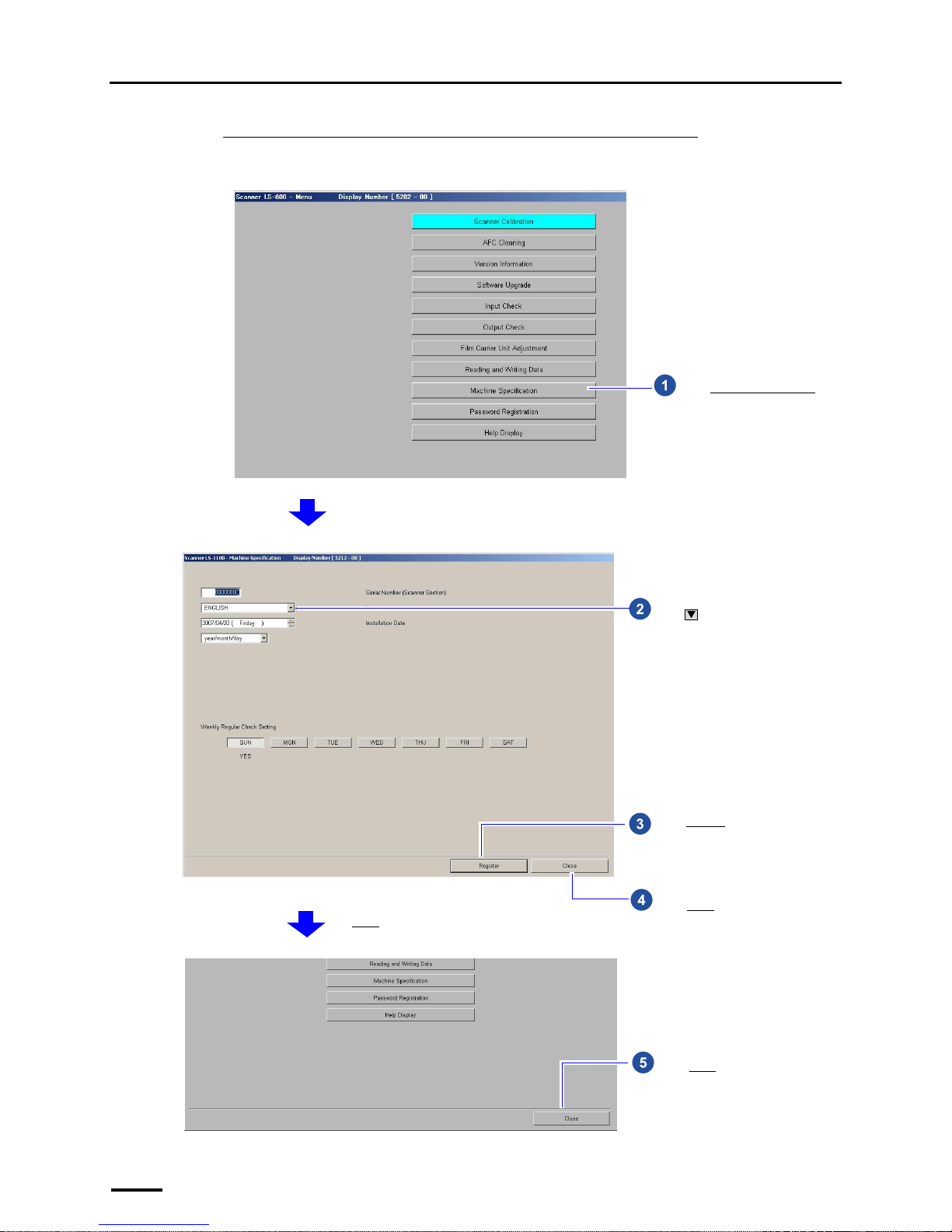
If connecting the scanner to the PC on which the controller is not installed
Change the language to be used as needed.
Example: Menu display
Click Machine Specification.
S5202-00-UM02
Click and select a language to be
used for software displays.
Click Register.
Click Close.
The Menu display is shown.
S5212-00-UM02
Click Close.
S5202-00-UM03
Page 63

7 Connecting the power supply and setting the USB driver
55
This completes configuring the USB driver settings.
Perform ☞8 Configuring various settings.
Page 64
8 Configuring various settings
56
8 Configuring various settings
This section explains minimum required settings to scan films.
For configuring settings other than those explained in this section, see the Operator's Manual as needed.
• For details about how to access the Operator's Manual, see Accessing the HELP display in the Starting Guide.
8.1 Configuring the USB power Management setting
This section uses Windows XP displays, but the procedures are the same for Windows Vista.
If the PC purchased from us is used, this step is not necessary.
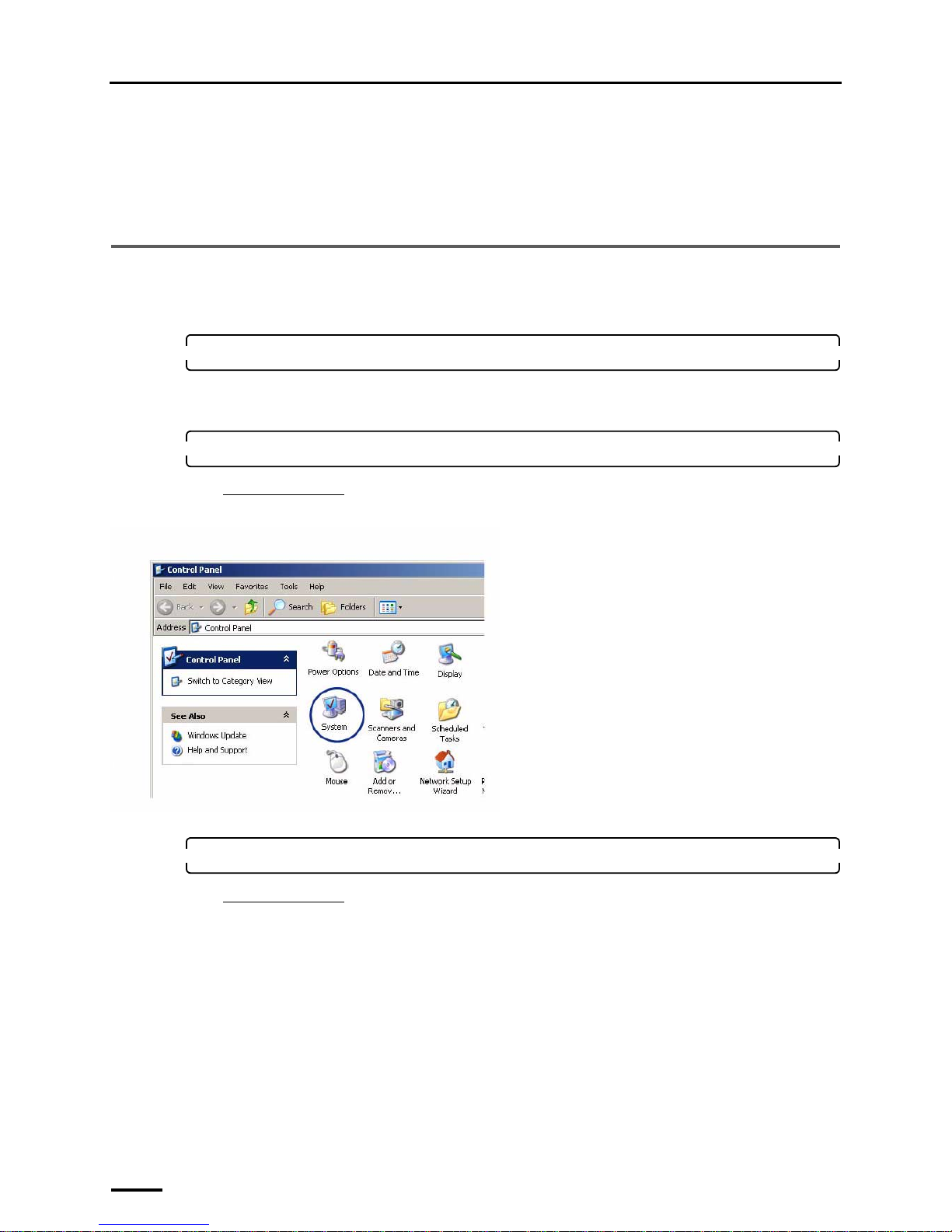
1. Access the Control Panel display.
Bringing up the display
Start → Control Panel
2. Double-click the System icon.
For Windows Vista
Click the System and Maintenance icon.
The System Properties display is shown.
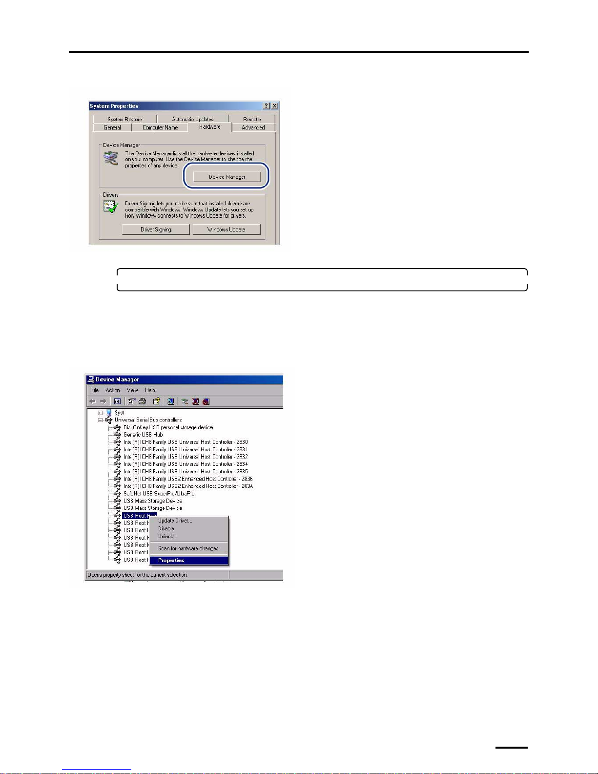
3. Select the Hardware tab and click Device Manager.
For Windows Vista
Click the Device Manager icon.
G089280
Page 65
8 Configuring various settings
57
The Device Manager display is shown.
4. Access the USB Root Hub Properties display.
The number of displayed USB Root Hub varies depending on the PC settings. Configure the settings for all
displayed USB Root Hub.
Bringing up the display
Double-click Universal Serial Bus controllers on the Device Manager display. → Right-click USB Root Hub. →
Click Properties.
G089281
G089283
Page 66
8 Configuring various settings
58
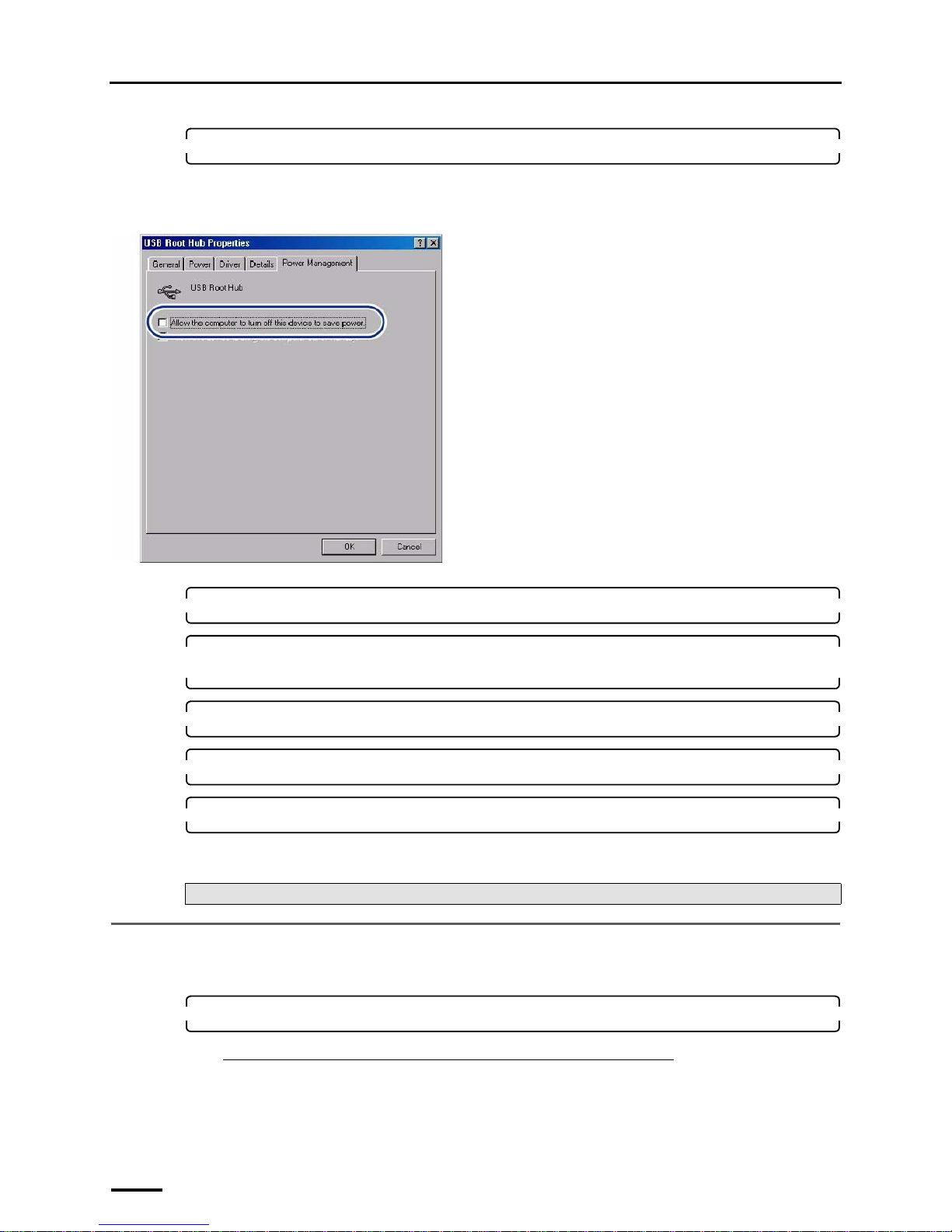
5. Select the Power Management tab.
Clear the check box of Allow the computer to turn off this device to save power.
Example: USB Root Hub properties display
6. Click OK.
7. Perform Step 4 and Step 5 to configure the Power Management setting for all displayed USB
Root Hub.
8. Click × in the upper-right corner of the Device Manager display to close it.
9. Click OK to close the System Properties display.
10. Click the close button in the upper-right corner of the Control Panel display to close it.
This completes configuring the USB power management settings.
8.2 Configuring the installation date and display settings
Enter the installation date or select the displayed language.
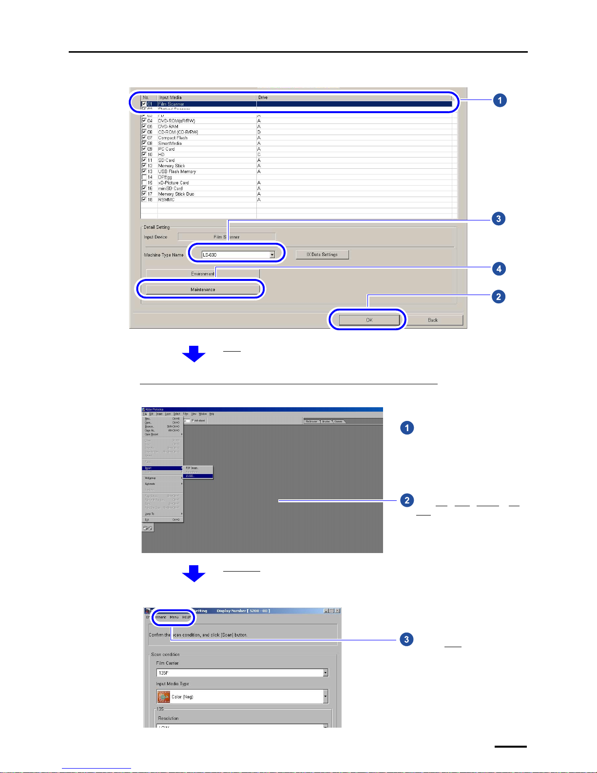
1. Access the Menu display.
If connecting the scanner to the PC on which the controller is installed
Bringing up the display
Click F on the Controller Main Display. → Management Tool → System management → Input Media → Select
Film Scanner in Input Media. → Click OK. → Select the model name. → Click Maintenance.
Next, go to ☞8.2 Configuring the installation date and display settings.
G089282
Page 67
8 Configuring various settings
59
Example: Input Media display
If connecting the scanner to the PC on which the controller is not installed
Example: Adobe Photoshop display
Example: Scan Setting display
S5113-00-UM00
The Menu display is shown.
Go to Step 2.
Start image editing software such as
Adobe Photoshop.
Select File→Read→LS-600 or LS-
1100.
S087590
The Scan Setting display is shown.
Click the Menu tab.
S5200-00-UM01
Page 68
8 Configuring various settings
60
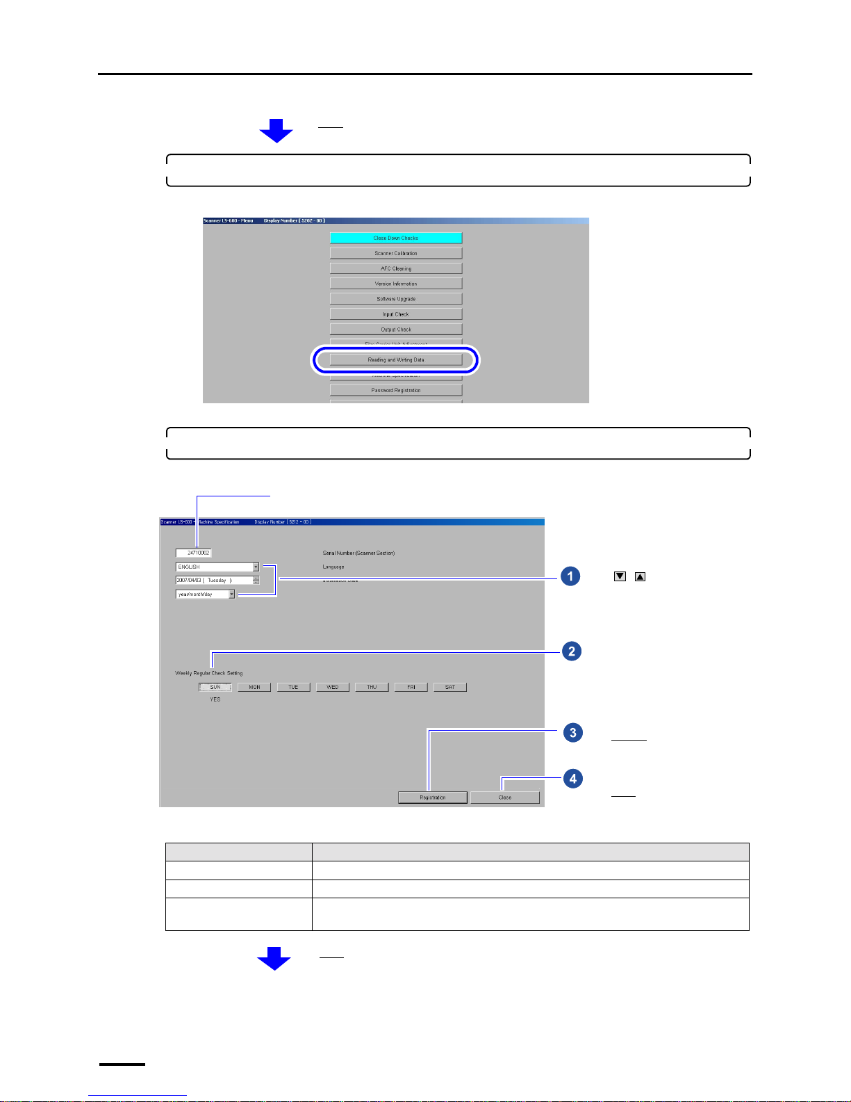
2. Click Machine Specification.
Example: Menu display
The Machine Specification display is shown.
3. Select the language, date and unit to be used for software displays.
Example: Machine Specification display
Item Setting
Language Select a language to be used for software displays.
Installation Date Enter the installation date.
Date and Time Display Select the displayed order of year, month and date.
(This setting can be configured only for the PC that the controller is not installed.)
The Menu display is shown.
S5202-00-UM03
Select the day to perform the weekly
regular check.
Click / to configure each
setting. (See the table below.)
Click Register.
Click Close.
The serial number of this product is shown.
S5212-00-UM01
The Menu display is shown.
Page 69
8 Configuring various settings
61
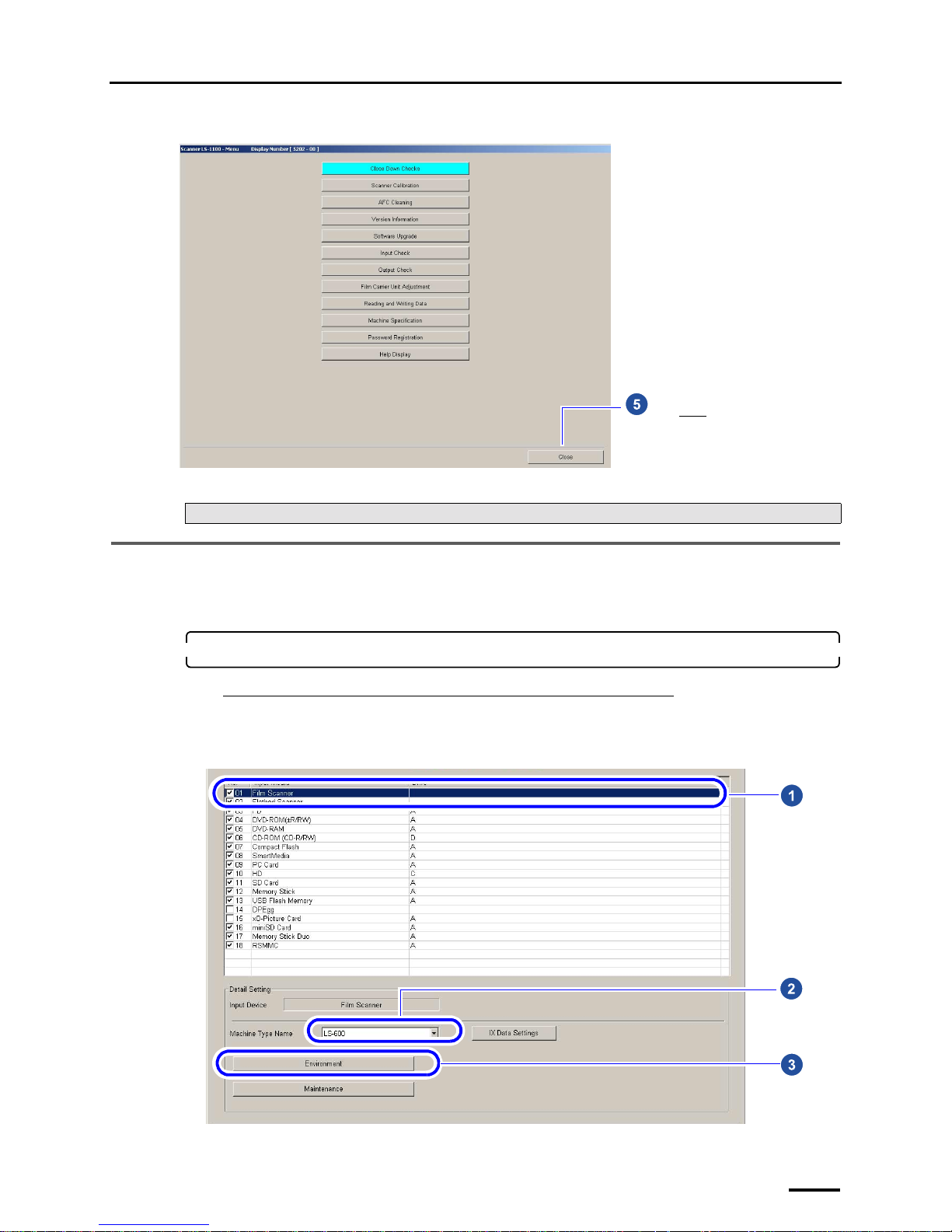
Example: Menu display
This completes configuring the installation date and display settings.
8.3 Configuring the display unit and resolution name settings
This section explains procedures of specifying names of the unit of images and resolution displayed on the Scan Setting
display.
1. Access the Environment display.
If connecting the scanner to the PC on which the controller is installed
Bringing up the display
Select the Film Scanner check box on the Input Media display. → Select the model name. → Click Environment.
Example: Input Media display
Next, go to ☞8.3 Configuring the display unit and resolution name settings.
Click Close.
S5202-00-UM01
S5113-00-UM00
Page 70
8 Configuring various settings
62
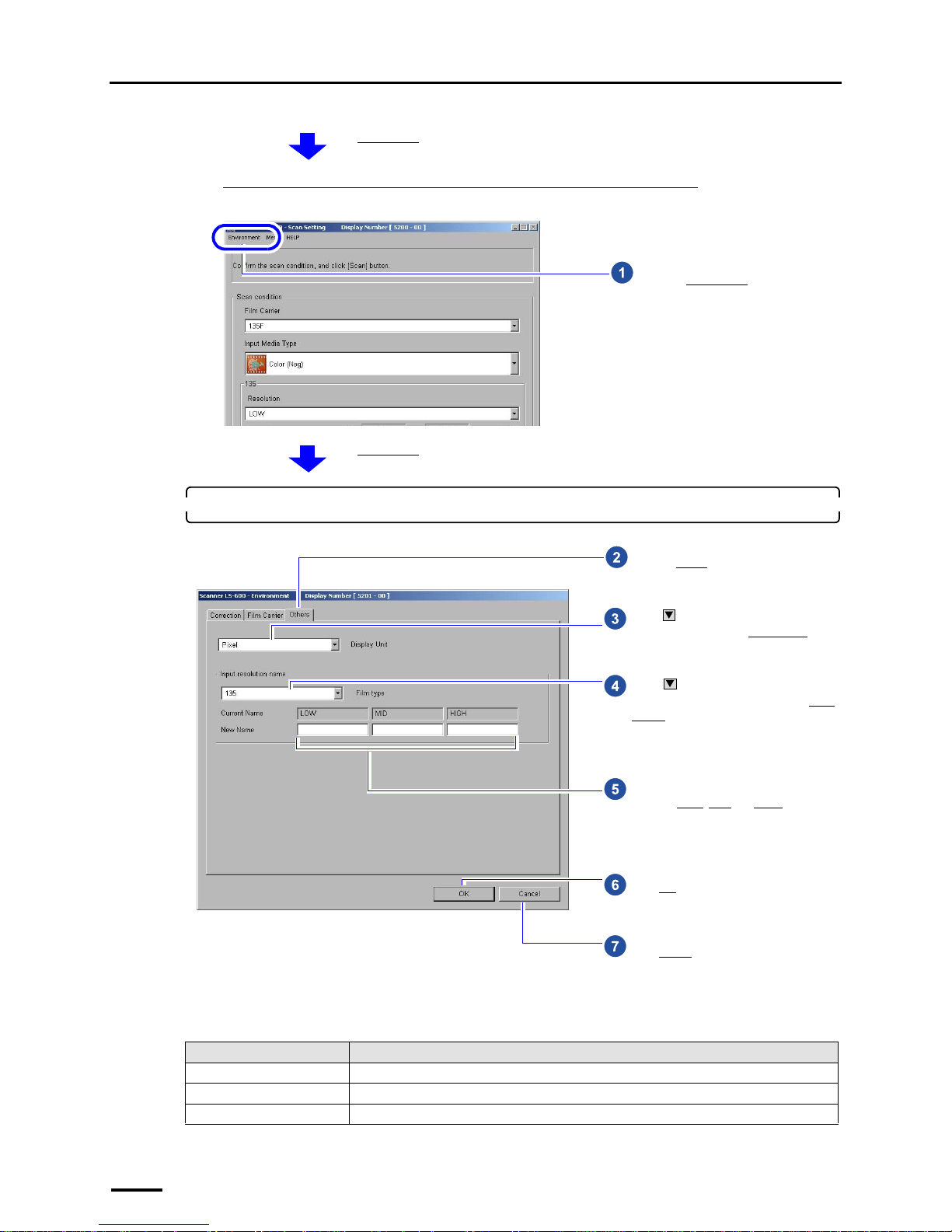
If connecting the scanner to the PC on which the controller is not installed
Example: Scan Setting display
2. Configure the settings on the Others tab.
Display Unit
This completes configuring the display unit and resolution name settings.
Item Setting
Pixel Displays in pixel unit.
inch Displays in 0.01 inch.
mm Displays in 0.1 mm.
The Environment display is shown.
Go to Step 2.
Click the Environment tab.
S5200-00-UM01
The Environment display is shown.
Click and select the unit of input
image size shown on the Scan Setting
display. (See the table below.)
Click to select the film type of the
resolution names to be changed in the Scan
Setting display.
Perform this operation only when you want
to change the resolution names.
Enter the names if you want to change the
names of LOW
, MID and HIGH. Up to ten
one-byte characters can be entered.
Click OK.
Click the Others tab.
Click Cancel.
S5201-00-UM03
Page 71

8 Configuring various settings
63
If connecting the scanner to the PC on which the controller is not installed
This completes all installation of the scanner.
Be sure to keep the supplied CD-ROM, manual and accessories.
Perform scanning and confirm that the scanner works normally.
• For details see 5.4 Scanning 135-type film in the Starting Guide.
If connecting the scanner to the PC on which the controller is installed
Create print channels.
Next, go to ☞9 Creating print channels.
Page 72
9 Creating print channels
64
9 Creating print channels
Creating print channels is necessary for connecting the scanner to the PC on which the controller is installed.
9.1 Creating print channels
Create print channels following the procedure.
Copy the created print channel and paste it to the empty channel, then create the channel to print from films.
1. Access the Controller Main Display.
Bringing up the display
Click Back on the Input Media display. → Click Back on the System management display. → Click End on the
Management Tool display.
2. Access the Print Channel Selection display.
Bringing up the display
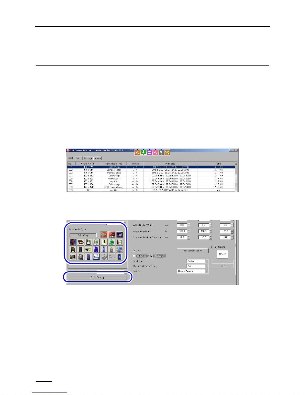
Click F on Controller Main Display. → Management Tool → Print Channel
Example: Print Channel Selection display
3. Select a source print channel and click Copy.
4. Select the copy destination of the print channel and click Paste.
5. Click Setting.
6. Select a film and click Scan Setting.
7. Configure the scanning condition on the Scan Setting display.
• For details, see the Starting Guide Scanning Setting display.
For details of the print channel, see the Operator's Manual Creating Print Channel in Various Settings.
This completes creating print channels.
This completes all installation of the scanner.
Be sure to keep the supplied CD-ROM, manual and accessories.
Print with the created print channel to confirm that the scanner works correctly.
S5102-00-UM00
S5103-00-UM00
Page 73
9 Creating print channels
65
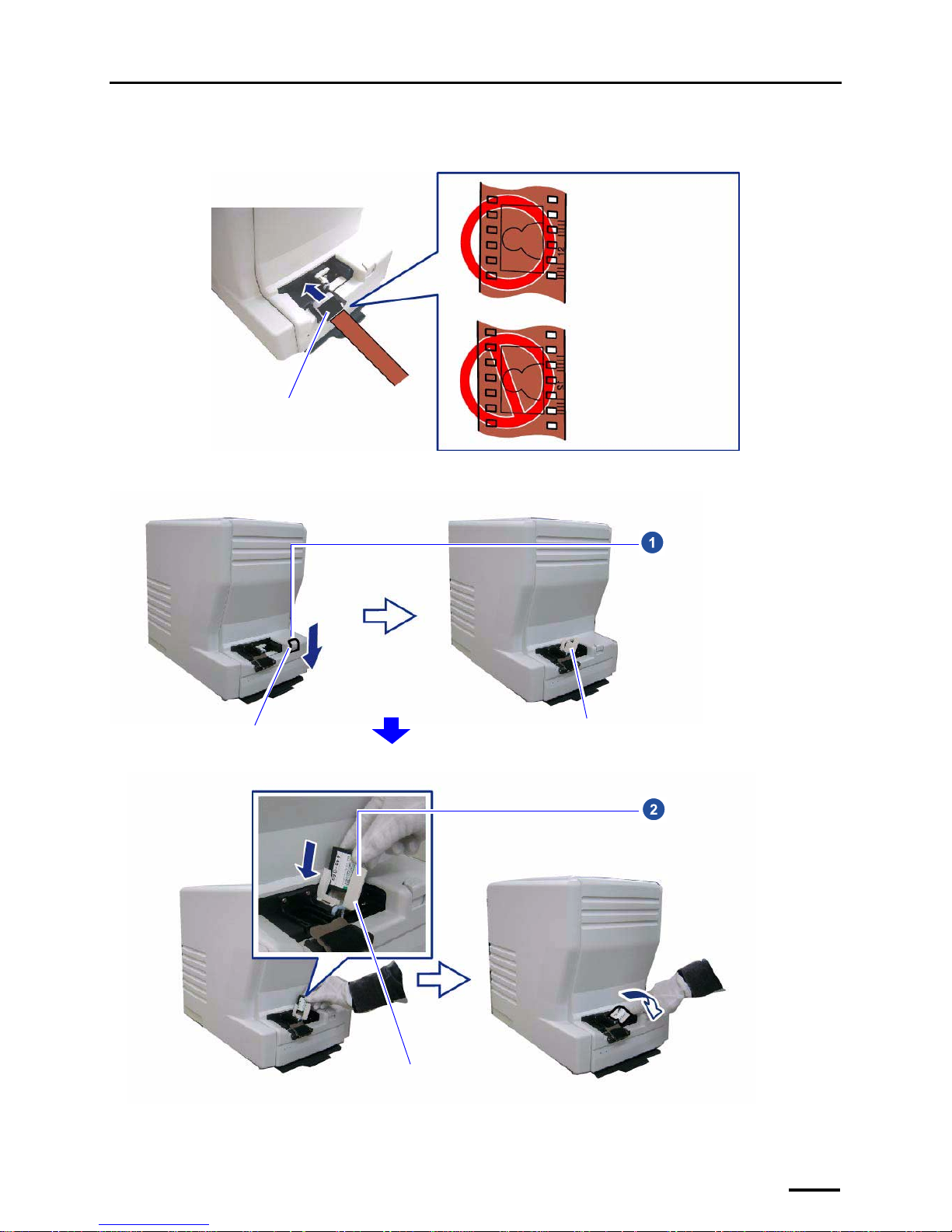
For details of inserting a film, see the following.
Example: Inserting a 135-type film
Example: Inserting an IX240-type film
Insert the film into the film
catcher. Hold the film so
that the image and the
frame numbers are facing
upwards. Then, insert the
film from the larger frame
number.
Film catcher
G088618
Eject button
Cartridge holder
Press the eject button in the arrow
direction to raise the cartridge
holder.
G088498
Cartridge holder
Set the IX240 film cartridge in the
cartridge holder, then push the
holder back down.
G088499
Page 74
10 Quick reference
66
10 Quick reference
10.1 If installing TWAIN driver or SYSTEM PROGRAM failed
This section explains the procedure to be performed if the scanner software does not start correctly because installing the
TWAIN driver or SYSTEM PROGRAM was failed.
If the system does not start normally even though Operation A is performed, go to Operation B.
Operation A
1. Install the TWAIN driver or SYSTEM PROGRAM again.
• Reinstall the software following the procedure of ☞5 Installing the TWAIN driver.
IMPORTANT
• Although some displays may not be shown during reinstallation because some steps are skipped,
continue installing the software.
If the Menu display is normally shown after the reinstallation, this completes installing the software.
Bringing up the display
On the Windows desktop display, click Start. → All Programs → Click LS-600 or LS-1100.
If it does not start normally, go to Operation B.
Operation B
This section uses Windows XP displays, but the procedures are the same for Windows Vista.
1. Access the Add or Remove Programs display or Programs and Features display.
For Windows XP
Bringing up the display
Start → Control Panel → Add or Remove Programs
For Windows Vista
Bringing up the display
Start → Control Panel → Programs → Programs and Features
IMPORTANT
• Be sure to follow the procedure below to uninstall the program.
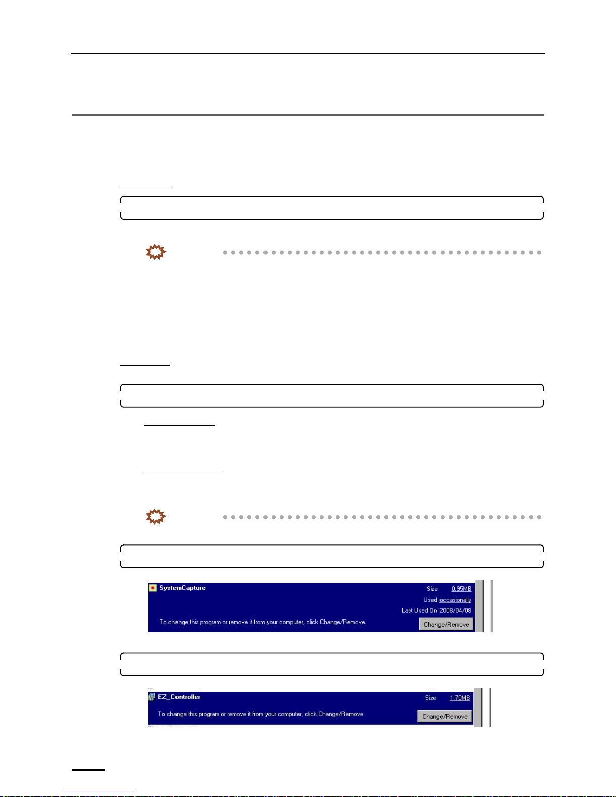
2. Select SystemCapture and click Change/Remove or Uninstall and Change.
Uninstallation of the SystemCapture starts.
3. Select EZ Controller and click Change/Remove or Uninstall and Change.
Uninstallation of EZ Controller starts.
S091122
S089526
Page 75
10 Quick reference
67
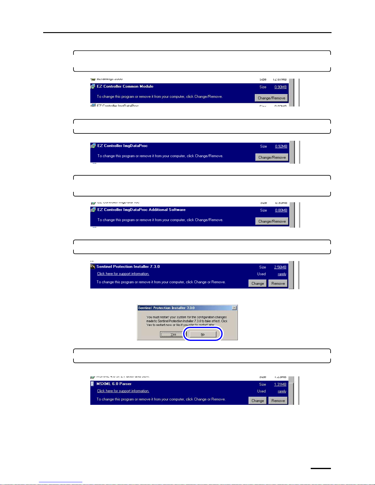
4. Select EZ Controller Common Module and click Change/Remove or Uninstall and
Change.
Uninstallation of EZ Controller Common Module starts.
5. Select EZ Controller ImgDataProc and click Change/Remove or Uninstall and Change.
Uninstallation of EZ Controller ImgDataProc starts.
6. Select EZ Controller ImgDataProc Additional Software and click Change/Remove or
Uninstall and Change.
Uninstallation of EZ Controller ImgDataProc Additional Software starts.
7. Select Sentinel Protection Installer 7.3.0 and click Remove or Uninstall.
If the following display is shown after the uninstallation is completed, select NO.
8. Select MSXML 6.0 Parser and click Remove.
For Windows Vista, skip this step because this software is not installed on Windows Vista.
Uninstallation of MSXML 6.0 Parser starts.
S089527
S089528
S091121
S089530
S089531
S089532
Page 76
10 Quick reference
68
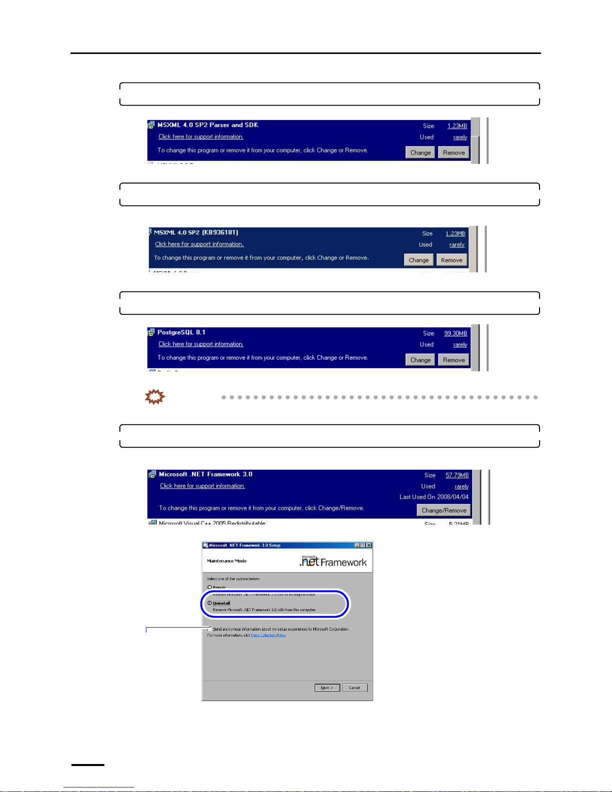
9. Select MSXML 4.0 SP2 Parser and SDK and click Remove or Uninstall.
Uninstallation of MSXML 4.0 SP2 Parser and SDK starts.
10. Select MSXML 4.0 SP2 (KB########) and click Remove.
For Windows Vista, skip this step because this software is not installed on Windows Vista.
Uninstallation of MSXML 4.0 SP2 (KB########) starts.
11. Select PostgreSQL 8.1 and click Remove or Uninstall.
Uninstallation of PostgreSQL 8.1 starts.
IMPORTANT
• After removing PostgreSQL8.1, manually delete the PostgreSQL folder in Program Files (C drive).
12. Select Microsoft .NET Framework 3.0 and click Change/Remove.
For Windows Vista, skip this step because this software is not installed on Windows Vista.
S089533
S091812
S089534
S091123
You do not need to
select this check
box.
S091124
Page 77
10 Quick reference
69
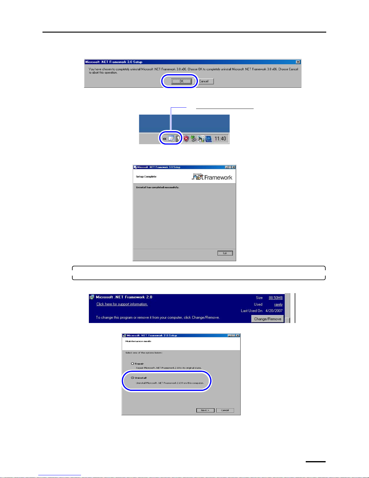
When the following display is shown, click OK.
Double-click the Microsoft .NET Framework 3.0 icon on the taskbar at the lower-right of the screen.
The confirmation display of processing status of the uninstallation is shown.
If the following screen is shown after the uninstallation is completed, click End.
13. Select Microsoft .NET Framework 2.0 and click Change/Remove.
For Windows Vista, skip this step because this software is not installed on Windows Vista.
S091125
The Microsoft .NET Framework 3.0 icon
G091230
S091127
S089535
S089536
Page 78
10 Quick reference
70
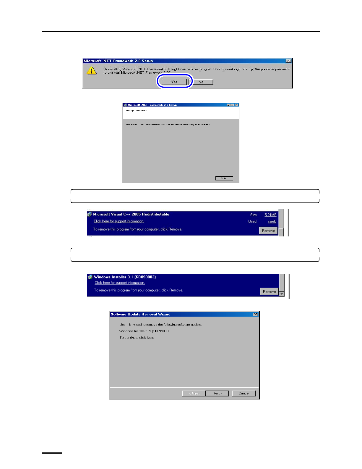
If the following display is shown, click YES.
If the following display is shown after the uninstallation is completed, click Finish.
14. Select Microsoft Visual C++ 2005 SP1 Redistributable and click Remove or Uninstall.
Uninstallation of Microsoft Visual C++ 2005 SP1 Redistributable starts.
15. Select Windows Installer 3.1(KB893803) and click Remove.
For Windows Vista, skip this step because this software is not installed on Windows Vista.
If the following display is shown, click Next.
S089537
S089538
S089539
S089540
S089541
Page 79
10 Quick reference
71
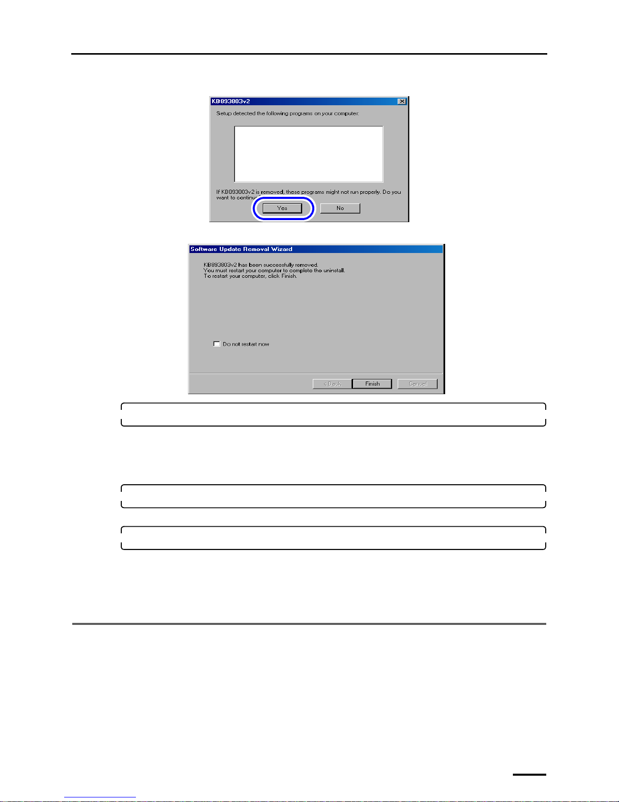
If the following display is shown, click YES.
If the following display is shown after the uninstallation is completed, click Finish, and restart the PC.
16. If there are the NoritsuSwitcher and EZLauncher folders in the Common folder, delete them.
Location of folder
C drive → Noritsukoki → Common
• NoritsuSwitcher
• EZLauncher
17. Select LS-600 or LS-1100, and click Change/Remove.
LS-600 or LS-600 is uninstalled.
18. Install the TWAIN driver or SYSTEM PROGRAM again.
• Reinstall the software following the procedure of ☞5 Installing the TWAIN driver.
If the Menu display is normally shown after the reinstallation, this completes installing the software.
Bringing up the display
On the Windows desktop display, click Start. → All Programs → Click LS-600 or LS-1100.
10.2 If connecting the USB cable and starting the PC before installing
the scanner software
This operation is necessary only for Windows XP.
If the USB cable is connected and the PC is started before TWAIN driver or SYSTEM PROGRAM is installed, the USB
scanner cannot be recognized. In such case, uninstall it.
The display below is shown after the PC starts up.
Program name
S089542
S089543
Page 80
10 Quick reference
72
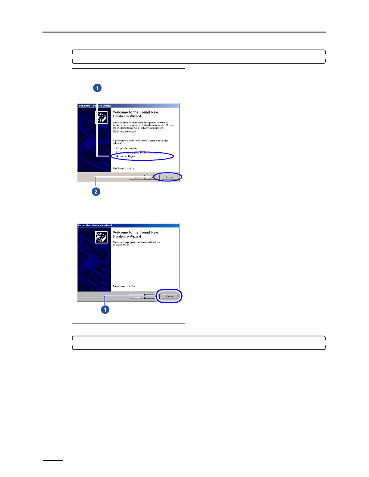
1. Follow the instructions shown on the display.
The Windows display is shown.
2. Access the Computer Management display.
Bringing up the display
Start → Right-click My Computer. → Manage
Pattern A
Pattern B
Select No, not this time.
Click Cancel.
Click Cancel.
Page 81
10 Quick reference
73
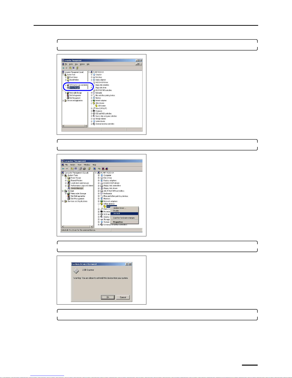
3. Click Device Manager.
4. Right-click USB scanner in Other devices, and click Uninstall.
5. Click OK.
6. Install SYSTEM PROGRAM again.
• For details, see ☞6 Installing the SYSTEM PROGRAM.
The display to install the USB driver is shown.
• Perform the operations from Step 2 in
☞7.2 Configuring USB driver settings.
Page 82

This page is intentionally blank.
 Loading...