

NORITAKE-ITRON VAF1613-2SSB technology data
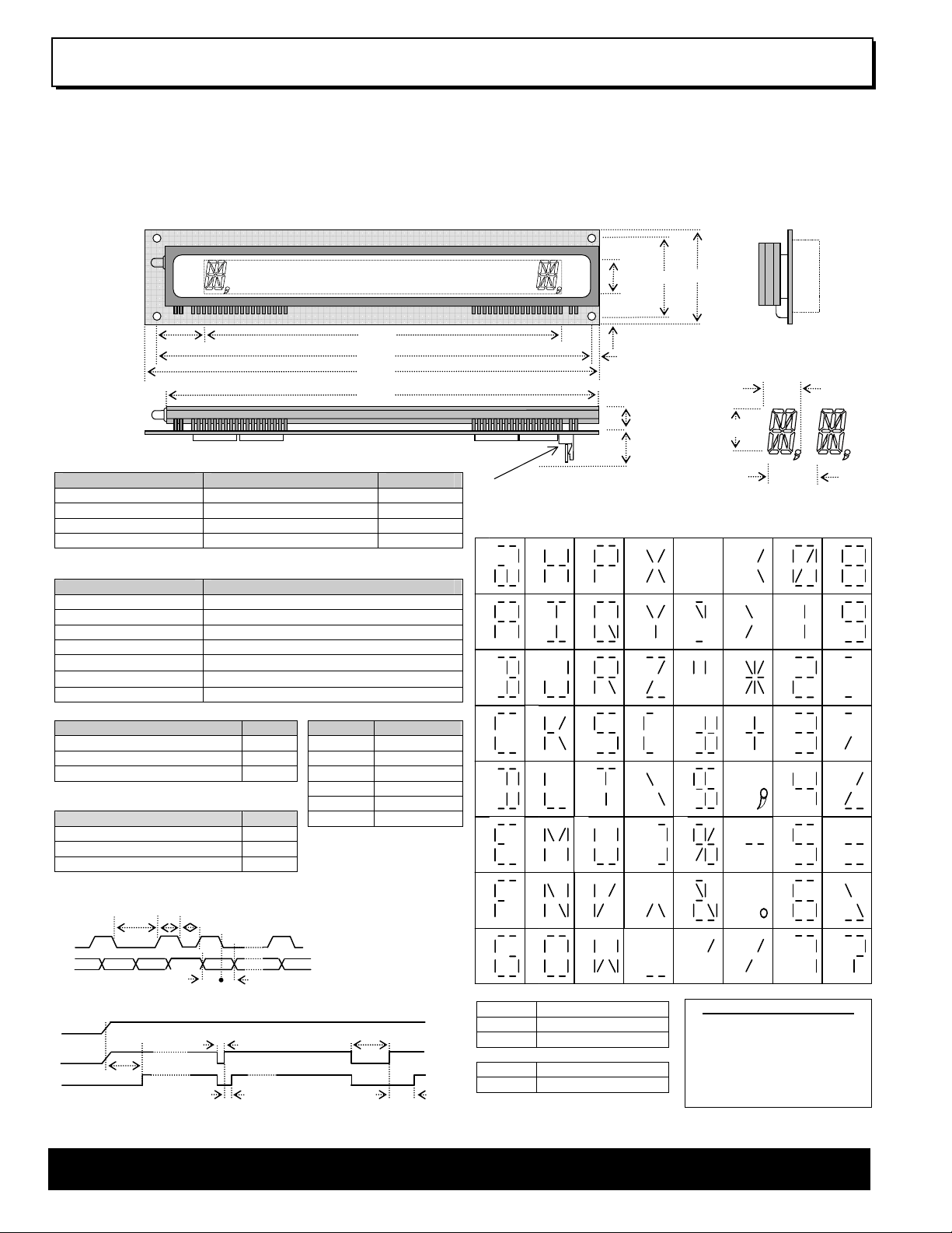
Vacuum Fluorescent Display Module VAF1613-2SSB
µ
1 Line x 16 Characters
13mm High 16 Segment Character
Single 5V Supply
High Brightness Blue-Green Display
64 Character Font Set
8 Bit Sync-Serial HCMOS Buffered Interface
This single board display module consists of a 16
character VFD, a DC/DC converter, plus a VFD controller,
refresh memory and a character generator.
21.2
174.0
207.0
217.0
205.0
ELECTRICAL SPECIFICATION
Parameter Value Symbol
Power Supply Voltage 5VDC +/- 5% VCC
Power Supply Current Typ. 600 mAdc ICC
Logic High Input 2.4VDC min. (VCC = 5V) VIH
Logic Low Input 1.0VDC max. (VCC = 5V) VIL
Note:- Power-on rise time for VCC should be less than 100ms.
OPTICAL and ENVIRONMENTAL SPECIFICATION
P2
Dimensions in mm & subject to tolerances. Mounting holes 4.0mm dia.
CHARACTER SET
00 18 20 28 30 38
08
Parameter Value
Character Size (X x Y) 7.0mm x 12.5mm
Character Pitch 11.0mm
01 19 21 29 31 39
09
Luminance Min 700 cd/m2 (200 fL)
Colour Of Illumination Blue-Green (505nm)
Operating Temperature
Storage Temperature
Operating Humidity 20 to 80% RH (non condensing)
SOFTWARE COMMANDS CONNECTOR P2
-40°C to + 85°C
-50°C to + 85°C
Instruction Hex Pin Function
02
03
0A
0B
Character Write 00-3F 1 +5V
Cursor Position AF=1...AE=16 A0-AF 2 CLK
Brightness Control E0-FF 3 NC
04
0C
4 D0
EXAMPLE INITIALISATION 5 RESET
Function Data 6 0V (GND)
Set Brightness (Display On) FFH
Set Buffer Pointer AFH
Send Data (00→3FH) X+X..
8 BIT SYNCHRONOUS TIMING
CK
LSB
VALID
DO
POWER ON RESET
Vcc
/RESET
DATA/COMMAND
A Short reset sets the display on/off as LK1 and positions the buffer pointer
at the left most character. A Long Reset causes the controller to re-initialise.
Min. 10ms
Busy
40µs
Min
Min
1
s
1µs
MSB
VALID
Min 100nsMin 200ns
SHORT RESET LONG RESET
Min. 50µs
Min.50µs Min. 2ms
LSB
At power on reset Display
On/Off is set as LK1 link
LK1 open - Display Off
LK1 closed - Display On
Note: For test mode
connect P1 Pin5 to Pin 11
Use the reset input prior to
every message for good
VALID
synchronization
Min. 2ms
.
05
06
07
0D
0E
0F
JP1 JUMPER LINKS
1 & 2 Clock or Data reset
2 & 3 Reset Low
2 & 4 Reset High
JP2 JUMPER LINKS
1 & 2 Clock Line Reset
2 & 3 Data Line Reset
If Clock or Data reset is selected line
must be held high for 250uS for short
reset, 2.5mS for long reset
37.0
45.5
15.0
15.0
4.0
7.0
11.5 max
12.5
15.5
11.0
10
11
12
13
14
15
16
17
1A
1B
1C
1D
1E
1F
22 2A
23
24
25
26
27
2B
2C
2D
2E
2F
32
33
34
35
36
37
3A
3B
3C
3D
3E
3F
CONTACT
Noritake Sales Office Tel Nos
Nagoya Japan: +81 (0)52-561-9867
Canada: +1-416-291-2946
Chicago USA: +1-847-439-9020
Munchen (D): +49 (0)89-3214-290
Itron UK: +44 (0)1493 601144
Rest Europe: +49 (0)61-0520-9220
www.noritake-itron.com
Subject to change without notice.
IUK Doc Ref:10730 Iss:1 30Jan07
NORITAKE ITRON VFD MODULES 1 x 16, 13mm Alphanumeric
 Loading...