

NORITAKE-ITRON GU128x64D-K610A8 technology data
Dot Graphic VFD Module GU128x64D-K610A8
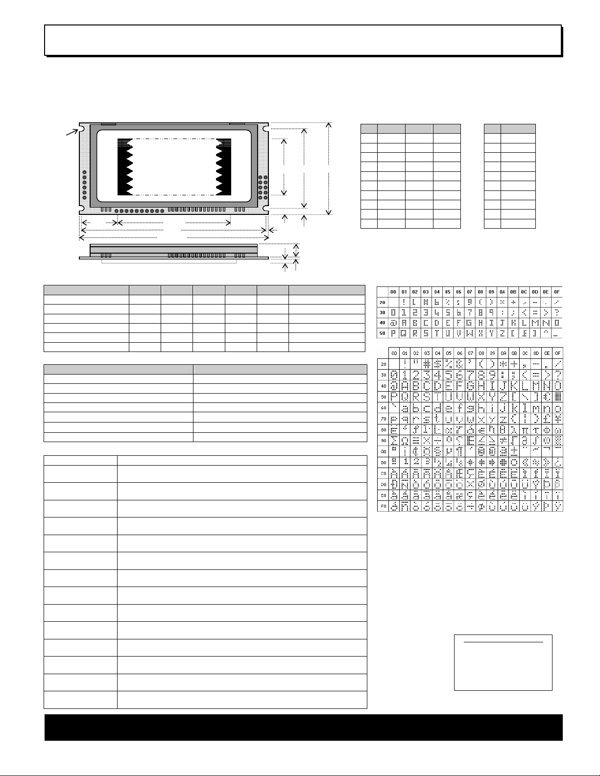
128 x 64 High Brightness Dot Graphic Display
Single 5V DC Supply
4 ASCII Fonts ( 5x5, 5x7, 10x14, 7x15 )
Asynchronous, SPI, I2C & Parallel interfaces
8 User I/O Pins with Key Scanning Capability
The module includes the VFD glass, VF drivers and microcontroller, character generation, interface logic and transformerless DC/DC converter. The interface type is selected by a push
button on the back of the module. Auto key scanning and general
I/O are available on port PA0 – PA7 for user control.
2.5∅ x 4
CON3
1
1
57.45
93.0
96.0 typ
17.6
CON2
1
CON1
28.65
1.5
10.7
ELECTRICAL SPECIFICATION
Parameter Sym Min Typ Max Unit Condition
Supply Voltage Vcc 4.5 5.0 5.25 V VSS=0V
Supply Current Icc - 410 - mA Vcc=5V All dots
Logic High Input VIH 3.0 - Vcc V VCC=5V
Logic Low Input VIL -0.5 - 1.5 V VCC=5V
Logic High Output VOH 4.2 - - V IOH =-3mA Vcc=5V
Logic Low Output VOL - - 0.6 V IOL = 20mA
ENVIRONMENTAL and OPTICAL SPECIFICATION
Parameter Value
Display Area (XxY mm) 57.45 x 28.65
Dot Size/Pitch (XxY mm) 0.3 x 0.3/0.45 x 0.45
Luminance 800 cd/m2 Typ
Colour of Illumination Blue-Green (Filter for colours)
Operating Temperature
Storage Temperature
Operating Humidity (non condensing) 10 to 90% @ 25°C
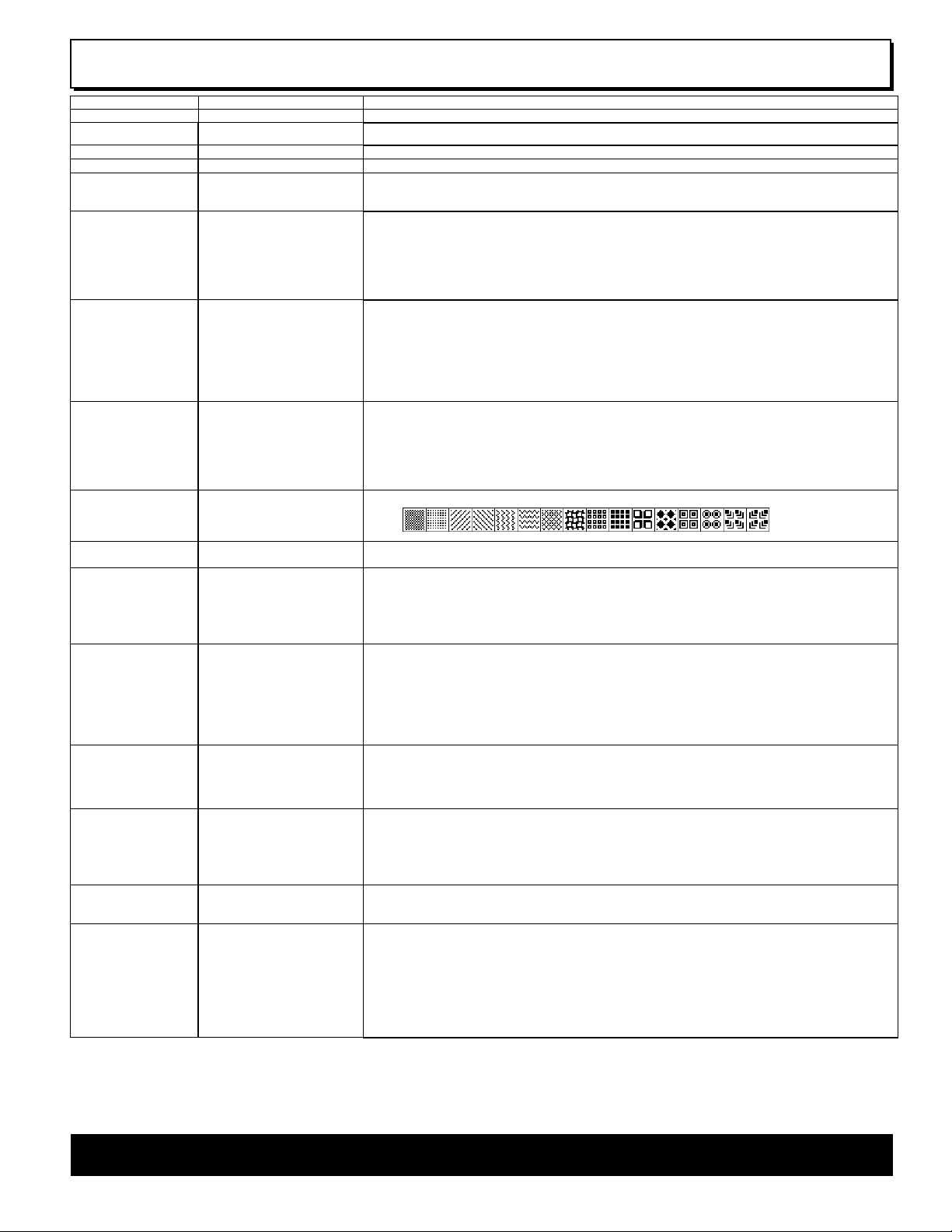
SOFTWARE COMMAND SUMMARY
Command Type Description
Cursor Move ASCII commands for Back Space, Horizontal Tab, Line Feed, Home,
Character Write Display a character from the selected font and increments the cursor
Graphic Write Write graphical data directly to a display area in either orientation. It is
Macro Write Store combinations of commands and data in up to 8 macros to reduce
Area Control Set, clear, invert and outline an area of the display for easy creation of
Window Control Pre-define 2 areas of the display as windows in which commands and
Scroll Vertically or horizontally scroll data in either direction within an area
Flash / Wipe Flash selected window’s contents. / Perform a wipe action on the
Font Select Select proportional mini font, fixed spaced 5x7 font, fixed spaced 10x14
Key Scan Set I/O port to key scanning. The I/O ports are continuously scanned for
I/O Port Set I/O port direction. A ‘1’ indicates an input, a ‘0’ indicates an output. All
Brightness Set the display brightness. Level = F8H - FFH. F8H = display off. F9H =
Power On/Off Turn on VFD power supply (default)/Turn off VFD power supply (display’s
Set Up Display Set the serial communication interface. Clear or reset the display. Lock or
Vertical Tab, Carriage Return and Cursor Position
according to the write mode.
important to disable Hex receive mode. Set or clear individual pixels.
host communication time. Macro 0 operates at power on.
highlights and menu screens.
data for scroll, flash, wipe and pattern are active.
defined by window 1. Space padding, speed and repeat options.
selected window with predefined user patterns / wallpaper.
font. Use the extended font command for 7x15 font or advanced settings.
any key press and the connectivity data output to the serial port.
output lines are immediately set low.
minimum, FFH = maximum (default). Auto-fade to a defined level.
contents will be preserved). Current consumption is about 25mA.
unlock the EEPROM for macros and setup configuration.
-40°C to +85°C
-40°C to +85°C
2.4
40.5
3.0
7.9 typ
8.7 max
1.6
46.5 typ
Uses patent applied PSU which has no inductive components.
CON1
Pin Async SPI I2C
1 5V 5V 5V
2 Nc SCK Nc
3 RXD /SS SCL
4 Nc SIN Nc
5 0V 0V 0V
6 Nc SOUT Nc
7 TXD /IRQ SDA
8 /RES /RES /RES
9 MB MB MB
10 HB HB HB
Nc = Do Not Connect
Dimensions in mm & subject to tolerances.
Brown out detector active when RES is not connected.
CHARACTER SETS
MINI FONT (PROPORTIONAL SPACING)
5x7, 7x15 & 10x14 FONTS (FIXED SPACING)
The module defaults to an 8 line of 21 character display using
the 5x7 font with single pixel spacing. The cursor position
auto increments after each character write. The bottom left of
a character is placed at the cursor x,y. The M(odule) Busy
line indicates the module is busy when low. Connect the
H(ost) Busy input to the MBusy to disable handshaking. Use
the rear SMT button to select the configuration which is then
stored in EEPROM. To send commands as hexadecimal,
prefix the 2 bytes using character 60H.
Example: `10`3F`01 = Position dot x=64 y=1. To send
character 60H to the display, send 60H twice.
Please note that the module defaults to HEX Receive
Mode.
Subject to change
without notice.
Software command
syntax and port pin
out Copyright 2006
Noritake Co. Limited
Doc Ref: 10736 Iss.2
.
19 Jan 08
CON2
Pin Signal
1 0V
2 ENABLE
3 PA0
4 PA1
5 PA2
6 PA3
7 PA4
8 PA5
9 PA6
10 PA7
CONTACT
Noritake Sales Of fice Tel Nos
Nagoya Japan: +81 (0)52-561-9867
Canada: +1-416-291-2946
Chicago USA: + 1-847-439-90 20
Munchen (D): +4 9 (0)89-3214 -290
Itron UK: +44 (0)1 493 601144
Rest Europe: +49 (0)61-0520-9220
www.noritake-itron.com
NORITAKE ITRON VFD MODULES GU128x64D-K610A8

Dot Graphic VFD Module GU128x64D-K610A8
SOFTWARE COMMANDS
Instruction Data Format Description
Macro Start
(BUSY time depends on contents)
Back Space
(50µs)
Horizontal Tab
(50µs)
Line Feed
(50µs)
Home
(50us)
Vertical Tab
(50us)
Carriage Return
(50us)
Clear EOL
(2.5ms)
Test
(50µs)
Cursor Position
(50us)
Set Area
(50us + 1ms [last byte])
Clear Area
(50us + 1ms [last byte])
Invert Area
(50us + 1ms [last byte])
Set Outline
(50us + 1ms [last byte])
Clear Outline
(50us + 1ms [last byte])
Set Pixel
(50us)
Clear Pixel
(50us)
Graphic Write
(50us + 250us [each data byte])
Reset
(500us)
Write Mode
(50us)
Set Macro
(50us)
Brightness
(50us)
Erase Macros
(250ms)
Lock/Unlock EEPROM
(50us + 40ms [last byte])
Checksum
(50us)
Power On/Off
(50us)
Hex/Binary Mode
(50us)
Set Serial Comms 1BH + 49H + comms Set Asynchronous Communications. Takes affect at power-up or hardware reset.
Enable I/O Port
(50us + 80ms[last byte])
Set Port Lines
(50us)
Read Port
(50us)
Enable Key Scanning
(50us + 40ms[last byte])
Select Font (50us) 1CH / 1DH / 1EH Select font. 1CH = proportional mini font. 1DH= fixed spaced 5x7 font. 1E = fixed spaced 10x14 font.
Graphic Area Write
(50us + 250us [each data byte])
Hex Prefix
(50µs + 50us + command BUSY)
Character Write (500us) 20H - FFH Display character from selected font.
01H - 07H Start user defined macro 1-7.
08H Non destructive backspace. Cursor is moved left by the width of the currently select font. If the cursor is at the
left end of the display, no cursor movement is made.
09H Cursor is moved right by the width of the currently select font. If the cursor is at the end of the display, no
cursor movement is made.
0AH Moves the cursor down by the height of the currently selected font. If the cursor is at the bottom of the display,
no cursor movement is made.
0BH Moves the cursor horizontal position to 00H, the vertical positioning is dependent on the currently selected
font, allowing for immediate character writing in the top-left corner of the display.
0CH Moves the cursor up one character row. If the cursor is at the top of the top end of the display, no cursor
movement is made.
0DH Moves the cursor horizontal position to 00H. The vertical position is unchanged.
0EH Clear all characters from the current cursor position to the end of the display.
0FH Place module into self-test mode. The module will repetitively show a few test screens. The test mode will
stop on the next received byte.
10H + xpos + ypos Set the cursor position.
11H + xleft + ytop + xright + ybot Fill specified area. All dots within the specified area are illuminated. Please note that the cursor position is
affected with this command.
12H + xleft + ytop + xright + ybot Clear specified area. All dots within the specified area are cleared. Please note that the cursor position is
affected with this command.
13H + xleft + ytop + xright + ybot Invert specified area. All dots within the specified area are inverted. Please note that the cursor position is
affected with this command.
14H + xleft + ytop + xright + ybot Draw box outline. All dots within the specified outline are unchanged. Please note that the cursor position is
affected with this command.
15H + xleft + ytop + xright + ybot Clear box outline. All dots within the specified outline are unchanged. Please note that the cursor position is
affected with this command.
16H Illuminate a single pixel at the current cursor position.
17H Clear a single pixel at the current cursor position.
18H + len + data Write graphical data, length len, direct to display. See write mode command (1AH) for graphic orientation and
cursor movements.
19H Resets display to power-on defaults: - Display is cleared. 5x7 font selected. Write Mode = 00H
Brightness Level = 7. VFD Power = On.
1AH + data Bit 7 = graphic data orientation - 0 = horizontal, 1 = vertical (default = horizontal)
Bit 6 = cursor movement - 0 = horizontal, 1 = vertical (default = horizontal)
Bit 5 = cursor direction - 0 = forward, 1 = backwards (default = forwards)
Bit 4 = underscore cursor - 0 = off, 1 = on (default = off)
Bit 3 = underscore cursor - 0 = static, 1 = flash (default = static)
Bit 1/0 = pen type - 00 = overwrite, 01 = AND, 02 = OR, 03 = XOR (default = overwrite)
1BH + macro + len + data Send macro data to EEPROM. macro = 00H - 07H. Macro0 is executed at power-up only. A maximum of 468
bytes is allowed for macro data. The display may flicker whilst writing macro data.
1BH + level Set the display brightness. level = F8H - FFH. F8H = display off. F9H = minimum, FFH = maximum (default).
1BH + 4DH Clear all downloaded macros in EEPROM. Screen may blank momentarily while macro data is being erased.
1BH + 4CH / 55H All data contained within the non-volatile EEPROM is locked (4CH), and no changes are possible until the
unlock command (55H) is executed.
1BH + 43H All data received is added to the checksum. This command will read the lower 8-bits of that checksum, before
being cleared. Please note that the checksum is cleared when executing the test mode.
1BH + 50H / 46H 50H = Turn on VFD power supply (default).
46H = Turn off VFD power supply, display’s contents will be preserved.
1BH + 48H / 42H 48H = Enable hex receive mode, character 60H is interpreted as a hexadecimal prefix.
42H = Disable hex receive mode. Hex mode is enabled at power up.
Bit 7 = Automatic I/O Send On(1)/Off(0). Bit 6 = Packet Mode On(1)/Off(0).
Bit 5 = Communications Buffer On(1)/Off(0). Bit 2 = Parity Even(1)/None(0).
Bit 3/1/0 baud rate: - 000 = 4800 001 = 9600 010 = 19200 011 = 38400
100 = 57600 101 = 76800 110 = 1200 111 = 2400
Factory Default = 19200 with no parity, auto I/O send is off, packet mode off, buffer = off.
1BH + 44H + data Set I/O port direction. A ‘1’ indicates an input, a ‘0’ an output. All output lines are immediately set low. All input
lines have their pull-ups enabled. This value is stored in EEPROM and will automatically be set at power up.
1BH + 4FH + data Set Output lines on I/O port, a ‘1’ will set 5V on the output ports, or enable the pull-ups on the inputs.
1BH + 52H Read current I/O port status. A single byte is transmitted showing the current state of the I/O lines.
1BH + 4BH Set I/O port to key scanning. The I/O ports are continuously scanned for any key press. This mode is stored in
EEPROM and will automatically be selected at power up.
1FH + xl + yt + xr + yb + data Write graphic data within defined area. See write mode command (1AH) for graphic orientation and cursor
movements.
60H + dhH + dlH Write to the display module using a 2-byte hexadecimal number. dhH = high nibble, dlH = low nibble. E.g.
Sending `19 will reset the display.
NORITAKE ITRON VFD MODULES GU128x64D-K610A8
Dot Graphic VFD Module GU128x64D-K610A8
Window 1 Select (50us) 1BH + 80H Select window 1 so that window and area command functions operate on the underlying data or text scroll.
Window 2 Select (50us) 1BH + 81H Select window 2 so that window and area command functions operate on the underlying data.
Window Define
(50us + 60us[last byte])
1BH + 82H +xl+yt+xr+yb Define window co-ordinates.
Window Mode (50us) 1BH + 83H + mode Set window mode: - 00H = Invert, 01H = Clear, 02H = Fill, 03H = Pattern.
Window Show (50us) 1BH + 84H Make selected window visible.
Window Flash
(50us)
1BH + 86H + no Flash selected window’s underlying data.
Flash type depends on window’s write mode.
no = number of flashes. FFH = infinite, 00H = stop flashing.
Window Flash Speed
(50us)
1BH + 87H + speed Set flash rate of selected window: -
0 = ~15ms 1 = ~30ms 2 = ~45ms 3 = ~100ms
4 = ~150ms 5 = ~200ms 6 = ~250ms 7 = ~350ms
8 = ~500ms 9 = ~750ms 10 = ~1.0sec 11 = ~1.5sec
11 = ~2.0sec 13 = ~2.5sec 14 = ~3.0sec 15 = ~3.5sec
Speed bits 4-7 = flash on duration, bits 0-3 = flash off duration.
Default speed = 88H (500ms on, 500ms off).
Window Wipe Effect
(50us)
1BH + 88H + wipe Perform a wipe action on the selected window’s underlying data: -
00H = left to right cover 01H = right to left cover
02H = top to bottom cover 03H = bottom to top cover
04H = left to right uncover 05H = right to left uncover
06H = top to bottom uncover 07H = bottom to top uncover
08H = horizontal centre to edge cover 09H = horizontal edge to centre uncover
0AH = vertical centre to edge cover 0BH = vertical edge to centre uncover
Note: All uncover wipes will alter the window co-ordinates.
Window Wipe Speed
(50us)
1BH + 89H + speed Set the wipe effect speed (pixels per second) for the selected window.
00H = halt wipe
01H = ~17Hz 02H = ~35Hz 03H = ~52Hz 04H = ~70Hz
05H = ~87Hz 06H = ~105Hz 07H = ~122Hz 08H = ~140Hz
09H = ~157Hz 0AH = ~175Hz 0BH = ~192Hz 0CH = ~210Hz
0DH = ~227Hz 0EH = ~245Hz 0FH = ~262Hz 10H = ~315Hz
The wipe effect duration depends upon the size of the window. Default speed = 04H (~70Hz).
Window Pattern Select
(50us)
1BH + 8DH + pat Select pre-defined pattern (00H-0FH) for window: -
Window Pattern Data
(50us)
Window Pattern Option
(50us)
1BH + 8EH + data A user 16x16 pixel pattern (32 bytes) can be defined for the selected window.
All data should be in vertical format with D7 uppermost.
1BH + 8FH + option Window Pattern Options: -
Bit 3 = invert pattern data.
Bit 2 = pattern alignment on / off.
Bit 1 = pattern align with top(1) or bottom(0) of window.
Bit 0 = pattern align with left(1) or right edge of window.
Default option = 00H (pattern alignment off & not inverted).
Scroll Text In Window 1
(50us + no of data bytes * 50us
[last byte])
1BH + 90H + mode + no + data Scroll text data within area defined by window 1.
mode bits 1&0 = direction: 00 = Scroll Up 01 = Scroll Down 10 = Scroll Left 11 = Scroll Right
mode bit 4 = scroll window's contents (yes/no)
mode bit 5 = pad end of text with spaces (yes/no)
no = repeat number (00H = infinite)
data = text to be scrolled with 00H = end of text. Use 0DH for multi-line scrolling messages.
Up to 8 rows of text can be scrolled horizontally.
Scroll Speed
(50us)
1BH + 91H + speed Set window 1 scroll speed (pixels per second): -
00H = halt scroll
01H = ~35Hz 02H = ~70Hz 03H = ~105Hz 04H = ~140Hz 05H = ~175Hz*
06H = ~210Hz* 07H = ~245Hz* 08H = ~315Hz*
*Horizontal scroll only. Default speed = 02H (~70Hz).
Select Extended Font
(50us)
1BH + 98H + font Select extended font: -
bits 0-2 = font number: 00H = 5x5 ASCII mini font. 01H = 5x7 ASCII font. 02H = 10x14 ASCII font.
03H = 7x15 ASCII font. 04H = 5x7 Cyrillic font. 05H = 10x14 Cyrillic font.
bit 3 = proportional / fixed spacing. 1 = proportional, 0 = fixed.
bits 4-6 = horizontal font spacing 1-8 pixels, where 000 = 1 pixel through to 111 = 8 pixels.
Auto Fade
(50us)
1BH + 9CH + level Perform automatic fade to a defined level.
Bits 0-2 = luminance level, where 000 = off through to 111 = 100%.
Bits 4-5 = speed, where 00 = fast through to 11 = slow.
Command Delay
(50us + delay [last byte])
1BH + 9FH + delay Delay any pending commands: -
00H = wait for display scan to finish.
01H-F0H = multiple of 10ms delay period (10ms to 2.5 seconds).
F8H = wait for Scroll to finish.
FAH = wait for Window 1 Flash to finish.
FBH = wait for Window 2 Flash to finish.
FCH = wait for Window 1 Wipe to finish.
FDH = wait for Window 2 Wipe to finish.
Note: If scroll or flash is set to infinite repeat, the delay is ignored.
Important Notes: - Busy times are not inclusive of a 100us scan period, this must be taken into consideration. If the cursor is enabled, busy times will increase by
a further 50us. All coordinates are absolute. The origin (00H, 00H) is the top left of the display. All data shown is in hexadecimal format.
The Back Space (08H) command is disabled when using proportional font.
NORITAKE ITRON VFD MODULES GU128x64D-K610A8
A
A
Dot Graphic VFD Module GU128x64D-K610A8
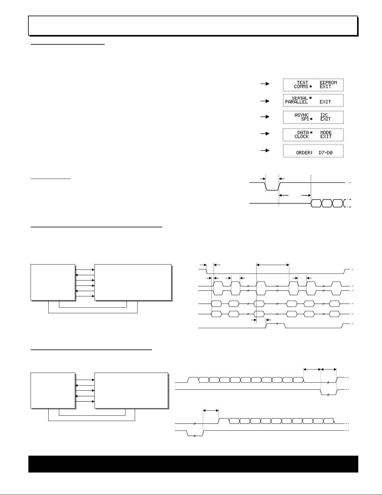
GU128x64D-K610A8 SETUP
The VFD module features a buffered asynchronous serial port and an unbuffered parallel port at CMOS level. Interface selection/set-up can be
made using the single push button switch on the back of the module. Pressing the switch for the first time will display the initial configuration
menu. On each subsequent switch press the menu pointer will advance. The current menu item will be selected if the switch is not pressed
within 2 seconds.
To select the required interface, press the switch until the ‘COMMS’ item has been selected.
Wait 2 seconds for the communication menu to be displayed. Press the switch until the required
communication method is selected. The factory default interface is “SERIAL”.
Wait 2 seconds for the interface menu to be displayed. Press the switch until the required
interface is selected. The factory default interface is “SPI”.
Wait 2 seconds for the related communication settings and select the property to be edited.
Wait 2 seconds to display the related communication settings. The current configuration is displayed
first. The factory default settings are “DATA: D7-D0”, “EDGE: RISE:”, “MODE: BUFFER”.
Note: Production items can be supplied with the configuration preset and fixed.
Interface selection example.
RESET TIMING
The module is reset when a low-level signal is applied to the /RES line. This will cause the
Module to clear the display, initialise the communication settings and set all power-up defaults.
During this initialisation period, the user must delay any transmission to the module. If the user
stores macros in EEPROM, the auto check and repair routine may take up to 9ms per stored
byte in addition to the standard reset time.
SYNCHRONOUS SERIAL COMMUNICATION (SPI)
/RES
DATA
>1.5us
30ms
Reset timing diagram
With synchronous communications enabled, data can be clocked into the VFD module using the rising or falling edge of SCK. This is
selectable by the push switch on the rear of the module which also sets the data order. By default, data is clocked in on the rising edge with the
most significant bit sent first. The host must provide adequate delays for the module to process the data. These busy times are specified in the
software command section. Alternatively the host can monitor the MB (Module Busy) line.
HOST
SYSTEM
I/O
I/O
I/O
I/O
I/O
I/O
SIN
SOUT
SCK
GU128x64D-K610A8
/SS
MB
/RES
VDD GND VDD GND
The /SS pin can be used as an enable pin if other devices are
connected to the SPI bus. The use of the /SS line is optional,
and can be permanently pulled low if not required. This is not
recommended since /SS ensures synchronisation of the SPI bus.
SCK (RISING)
SCK (FALLING)
SIN (D7-D0)
SIN (D0-D7)
>125ns
/SS
>65ns >125ns
D7
D0
MB
SPI Synchronous Serial Communication.
D6
D1
tBUSY + 10us
>125ns
D0
D7
<10us
D7
D6
D0
D1
D0
D7
ASYNCHRONOUS SERIAL COMMUNICATION
The asynchronous communication speed and parity can be set with the push switch on the rear of the module, or with the ‘SET SERIAL
COMMS’ command. The default settings are 19200 baud with no parity.
HOST
SYSTEM
TXD
RXD
DTR
CTS
I/O
RXD
TXD
GU128x64D-K610A8
HB
MB
/RES
VDD GND VDD GND
RXD
MB
synchronous serial communication from host system to VFD module.
The host busy line (HB) stops the module from sending data
to the host until the line falls. The use of the HB and MB lines
are optional, and can be connected together if not required.
TXD
HB
synchronous serial communication from VFD module to host system.
START
D0
D1 D2 D3 D4 D4 D5 D6
>2us
START
D0
D1 D2 D3 D4 D4 D5 D6
D7
PARITY
<10us tBUSY
STOP
D7
PARITY
STOP
NORITAKE ITRON VFD MODULES GU128x64D-K610A8
 Loading...