

NORITAKE-ITRON GU128x32D-7806A technology data
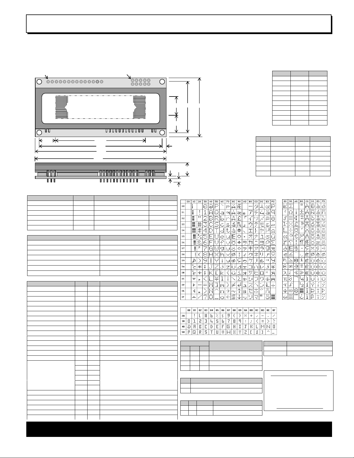
128x32
Dot Graphic (
2/3/4 x 16+ characters
)
The module includ
es the Vacuum Fluorescent Display glass, VF drivers
CN1 - PARALLEL INTERFACE
Noritake Sales Office Tel Nos
C
N2 – SERIAL
INTERFACE
ELECTRICAL SPECIFICATION
SOFTWARE COMMAND SUMMARY
OPTICAL and ENVIRONMENTAL SPECIFICATIONS
CN1 Pin 3 Function
Async. Serial Mode
Font
CHARACTER SET
Font
*/RESET = Jumper J6.1 & J6.2
BUSY = Jumper J6.2 & J6.3
80.0 8.3
max 2.0 max
1.6 9.78
54.89 75.0 80.0
8.535
13.93 31.0 36.0
2.5 Pin 1
Pin 1
9.78
Dot Graphic VFD Module GU128x32D-7806A
q
q Single 5V Supply
q High Brightness Blue Green Display
q Operating Temp -40°C to +85°C
q 6 Multi Sized Fonts (Katakana / International)
q 4/8 Bit Parallel LCD & Serial Interfaces
CN1
and micro-controller ICs with refresh RAM, character generator and
interface logic. The 4/8 bit parallel & serial bi-directional interfaces are
5V TTL/CMOS compatible. The command set is LCD compatible with
extended graphic functions.
CN2
Dimensions in mm &
subject to tolerances.
Mounting holes
3.2mm dia.
Pin Async SPI
1 5V 5V
2 NC SCK
3 RXD /SS
4 LINK1 SIN
5 0V 0V
6 LINK2 SOUT
7 TXD NC
8 /RES /RES
9 MB MB
10 HB HB
NC = Do Not Connect
Pin Sig Pin Sig
1 GND 2 VCC
3 NC* 4 RS
5 R/W 6 E
7 D0 8 D1
9 D2 10 D3
11 D4 12 D5
13 D6 14 D7
Pin 3 can be changed to /RESET or
BUSY terminal and selectable by
jumper J3 (2-3) or J3 (1-2)
J3 Function
2 & 3 / Reset
1 & 2 Busy
All J5 links & J6 should be open for
Parallel operation
CONTACT
Nagoya Japan: +81 (0)52-561-9867
Canada: +1-416-291-2946
Chicago USA: +1-847-439-9020
Munchen (D): +49 (0)89-3214-290
Itron UK: +44 (0)1493 601144
Rest Europe: +49 (0)61-0520-9220
www.noritake-itron.com
Subject to change without notice.
IUK Doc Ref: 11120 Iss:2 30 May 08
Parameter Symbol Value Condition
Power Supply Voltage VCC 5.0VDC +/- 5% GND=0V
Power Supply Current ICC 250mADC typ. VCC=5V
Logic High Input VIH 0.8VDC min. Vcc max. VCC=5V
Logic Low Input VIL 0VDC min 0.6VDC max. VCC=5V
Logic High Output VOH 3.5VDC min. Vcc max. IOH=-10uA
Logic Low Output VOL 0VDC min 0.6VDC max. IOL =4mA
Parameter Value
Display Area (XxY mm) 54.89 x 13.93
Dot Size/Pitch (XxY mm) 0.33 x 0.34 / 0.43 x 0.44
Luminance 800 cd/m2 Typ.
Colour of Illumination Blue-Green (Filter for colours)
Operating Temperature
Storage Temperature
Operating Humidity (non condensing)
-40°C to +85°C
-40°C to +85°C
20 to 80% RH @ 25°C
Instruction R/W RS D0-D7
Clear Display L L 01H
Cursor Return Home L L 02H
Entry Mode Set L L 04H-07H
Display ON/OFF L L 08H-0FH
Cursor Shift Left L L 10H
Cursor Shift Right L L 14H
Display Shift Left L L 18H
Display Shift Right L L 1CH
Select 4/8 bit interface L L
20H (4Bit) / 30H (8Bit) + luminance
Display Luminance L H 00H-03H (must follow above command)
Set CG RAM Addr. L L 40H-7FH
Set DD RAM Addr. L L 80H-E7H
Read BUSY/Addr. H L 00H-FFH D7 Busy = High
Read Data from RAM H H 00H-FFH
Set Graphic Cursor L L
Set Area Commands
L L
L H
L H
L H
L H
L H
Write Graphic Image L H
Set Font / Spacing / Line L L
F0H + xpos + ypos
F1H + x1 + y1 + x2 + y2 + cmd
where cmd 49H = Invert Area
46H = Fill Area
43H = Clear Area
4FH = Set Outline Box
6FH = Clear Outline Box
F1H + x1 + y1 + x2 + y2 + cmd + data
F2H + font style / line set
User Expansion Ports L L F4H-F8H Set, write and read user ports
Set RS Low 0FH Serial Comms. only
Read Data FEH Serial Comms. only
Read Cursor Position FFH Serial Comms. only
2.5
Standard Fonts LCD Katakana
UDF1
UDF2
UDF3
UDF4
UDF5
UDF6
UDF7
UDF8
UDF1
UDF2
UDF3
UDF4
UDF5
UDF6
UDF7
UDF8
NOTE: UDF characters are available using 5x7 font only.
Proportional Mini Font
J5
1-2 3-4 7-8
O O O 9600, N, 8, 1
L O O 19200, N, 8, 1
O L O 38400, N, 8, 1
X X L Self Test Mode
Serial / Parallel Selection
J6 Interface
Open Sync Serial / Parallel (default)
Link
Parallel Interface Type (M68 / i80)
Asynchronous Serial
J2 J4 Mode Signals
1-2 1-2 i80 Pin 5 = /WR, Pin 6 = /RD
2-3 2-3 M68 Pin 5 = R/W, Pin 6 = E
Copyright 2007 Noritake Itron Corp. Japan
International
Configuration
NORITAKE ITRON VFD MODULES GU128x32D-7806A
SOFTW
ARE COMMANDS
r write. If set to ‘1’, the address
Dot Graphic VFD Module GU128x32D-7806A
Instruction / Busy time Data Format (RS = 1) Description
UDF Write 00H – 0FH Write user defined character 1-8 to the current cursor location on the display.
Data Write
(40us – LCD compatible mode)
(250us – Graphic mode)
00H – FFH Write data to the display. In normal (LCD compatible) mode of operation, data is written to the display data
(DD RAM) or character generator (CG RAM).
When using the graphical data commands (F0H, F1H & F2H), data is written direct to the display and is not
stored in DD RAM. Data write busy times will increase when using the graphic functions.
Data Read
(40us – LCD compatible mode)
00H – FFH Read data from the display. In normal (LCD compatible) mode of operation, data is read from the display
data (DD RAM) or character generator (CG RAM)
Instruction / Busy time Data Format (RS = 0) Description
Status / Cursor Position
Read
(40us – LCD compatible mode)
Display Clear
(150µs)
Cursor Home
(500µs)
Entry Mode
(40µs)
00H - FFH D0 – D6 of read corresponds to the current cursor position. D7 shows the status of busy.
01H Fills all locations in the display data (DD) RAM with 20H (blank character). The address counter is set to 0 in
the DD RAM. The address counter is set to increment on each data read/write. Any display offset (using the
display shift command) is removed.
02H The address counter is set to 0 in the DD RAM. Any display offset (using the display shift command) is
removed.
04H – 07H Bit 1 is used to select the direction of the address counter on each data read o
counter is incremented. If set to ‘0’, the address counter is decremented.
Bit 0 enables the display to shift on each data read/write. If this bit is set to ‘1’, the display is shifted with the
cursor. The display shift direction depends upon the address counter direction (bit1). If this is set to
increment, the display is shifted left, if the address counter is set to decrement, the display is shifted right.
Note: When display shift is enabled, the data write busy time can increase by 150us.
Display Control
(50us)
08H-0FH Bit 2 is used to enable or disable the display. If this bit is set to ‘0’ the VFD’s power supply is turned off to
reduce power consumption.
Bit 0 enables the flashing block cursor. Note: If the cursor is enabled, busy times can increase by 20us.
Cursor Shift Left
(40us)
Cursor Shift Right
(40us)
Display Shift Left
(150us)
Display Shift Right
(150us)
Select 4 bit interface
(40µs)
10H Shift the cursor position (address counter) one position to the left.
14H Shift the cursor position (address counter) one position to the right.
18H Shift the display left, one character position.
1CH Shift the display right, one character position.
20H + lum (RS=1)
Enables 4-bit communications. Data is received on DB4-DB7 only. Two writes are required to send one data
byte. The most significant nibble should be sent first. Refer to the ‘Parallel Communications’ section for more
information. The lum value sets the displays brightness, and must be sent with the RS line high: 00H = full brightness, 01H = 75%, 02H = 50% & 03H = 25%.
Select 8 bit interface
(40µs)
Set CG Address
(40us)
Set DD Address
(40us)
Set Graphic Cursor
(40us)
*Note
Set Area
(40us + 500us[cmd byte])
30H + lum (RS=1) Enables 8-bit communications. Data is received on DB0-DB7. The lum value sets the displays brightness,
and must be sent with the RS line high: - 00H = full brightness, 01H = 75%, 02H = 50% & 03H = 25%.
40H – 7FH Set the character generator address (CG RAM). All written data is placed within the user definable character
area.
80H – E3H Set the display data address (DD RAM). 80H – 8FH = 1st line. C0H – CFH = 2nd line. 94H – A3H = 3rd line.
*Note
F0H + xpos + ypos Set the absolute cursor position. xpos = 0 – 127, ypos = 0 – 47.
D4H – E3H = 4th line
Co-ordinates should be written with RS line set high.
F1H + x1 + y1 + x2 + y2 + cmd
Area Commands: - ‘I’ - invert area, ‘F’ – fill area, ‘C’ = clear area, ‘O’ – set outline, ‘o’ – clear outline.
All area commands should be preceded with the area co-ordinates. X1 Y1 left top X2 Y2 bottom right.
Co-ordinates, command and graphical data should be written with RS line set high.
Write Graphic Image
Set Font / Lines
(40us)
*Note
Port Configure
F1H + x1 + y1 + x2 + y2 + cmd
F2H + font / line number
F4H + byte
Image Commands: - ‘H’ – write horizontal graphical data with horizontal cursor movement.
‘V’ – write vertical graphical data with horizontal cursor movement.
‘h’ – write horizontal graphical data with vertical cursor movement.
‘v’ – write vertical graphical data with vertical cursor movement.
Graphical data should immediately follow the ‘H’, ’h’, ’V’ and ‘v’ commands.
Co-ordinates, command and graphical data should be written with RS line set high.
Select font type, font size and font spacing. Select number of lines to display in LCD emulation mode.
Font commands: ‘A’ or ‘a’ = 64 character mini-font.
‘B’ = 5x7 font with Katakana. ‘b’ = 5x7 font with International.
‘C’ = 10x14 font with Katakana. ‘c’ = 10x14 font with International.
‘D’ = 7x7 LCD font with Katakana. ‘d’ = 7x7 LCD font with International.
‘E’ = 7x15 font with Katakana. ‘e’ = 7x15 font with International.
‘F’ and ‘f’ = 20x28 font using pixel doubling of ‘C’ and ‘c’.
Font spacing: ‘P’ = Proportional, ‘M’ = Mono-spaced, ‘1’ or ‘2’ = 1 / 2 pixel inter-character spacing
Display Lines: ‘L’ = 2 Lines with 7x7 fonts, ‘3’ = 3 Lines with 7x7 fonts, ‘4’ = 4 Lines with 7x7 fonts.
Font / line commands should be written with RS line set high.
Bit 7 High = I/O Port, Low = Serial Port. See extended port and serial commands.
Read Port Status F5H The current port status is read with RS high. See extended port and serial commands.
Port Out / Serial Send
F6H + byte byte is output from the port. In serial mode check the busy status before sending again.
Port In / Serial Read F7H The current port levels or buffered received data can be read with RS high.
Port Buffer Send
F8H + size + data
Up to 128 bytes of data can be buffered before being transmitted from the serial port.
Instruction / Busy time Data Format Additional Serial Data Commands
Set RS Low 0FH Set the RS line low for the following byte only. Used in serial communications only.
Read Data FEH Read data at current cursor position. This command is used with serial communications only.
Read Cursor Position FFH Read current cursor position. This command is used with serial communications only.
Note: After these commands are executed, the cursor will be disabled and any character data will be written to the display only, and not the DD RAM. Any subsequent LCD compatible command will
re-enable the cursor and allow for DD RAM writing.
NORITAKE ITRON VFD MODULES GU128x32D-7806A
8-Bit Data Read Timing Diagram.
8-Bit Data Write Timing D
iagram.
.
UPPER NIBBLE
LOWER NIBBLE
command to set either 4 or 8 bit mode.
Dot Graphic VFD Module GU128x32D-7806A
GRAPHICAL DATA WRITES
X1, Y1
DATA
DIRECTION
Vertical Data & Horizontal
Movement
MSB
X1, Y1
MSB
DATA
DIRECTION
Vertical Data & Vertical
Movement
X1, Y1
MSB
Horizontal Data & Horizontal
DATA
DIRECTION
Movement
X1, Y1
DIRECTION
MSB
Horizontal Data & Vertical
Movement
DATA
PARALLEL COMMUNICATIONS
This module has a fast latching 8-bit data bus. The ‘RS’ and ‘R/W’
control lines should be set prior to the rising edge of the ‘E’ enable line.
Data is clocked in on the falling edge of the enable line. The busy line
should be checked before sending data.
HOST
SYSTEM
I/O
I/O
I/O
I/O
I/O
D0-7
GU128x32D-7806A
E
RS
R/W
BUSY
VDD GND VDD GND
The busy state can be monitored on D7 when reading the DDRAM
address (RS line low). The busy state can also be monitored directly
from CON1 pin 3 if link J3 is set to 1&2.
R/W
RS
E
D0-D7
BUSY
R/W
>30ns
>30ns
>25ns
>20ns
>100ns
<120ns
tBUSY
HOST
SYSTEM
I/O
I/O
I/O
I/O
I/O
D4-7
GU128x32D-7806A
E
RS
R/W
BUSY
4-Bit Data/Command Write Timing Diagram
R/W
RS
>30ns
E
D4-D7
BUSY
>25ns
>20ns
>100ns
RS
>250ns
E
<250ns >50ns
D0-D7
The data bus width can be selected for 4-bit operation, using data lines
D4-D7. Within this mode, two writes are required to send one data byte.
VALID
The high nibble (bits 4-7) should be sent first, followed by the low nibble
(bits 0-3). The busy state is not triggered between nibbles. It is
VDD GND VDD GND
>100ns
important that the status is NOT read within 40us of sending the
>25ns
>20ns
<120ns
>100ns
tBUSY
NORITAKE ITRON VFD MODULES GU128x32D-7806A
 Loading...