

NORITAKE-ITRON GU126x64D-K610A4 technology data

Dot Graphic VFD Module GU126x64D-K610A4
y
q 126 x 64 High Brightness Dot Graphic Displa
q Single 5V DC Supply
q 3 ASCII Fonts ( 5 x 5, 5 x 7, 10 x 14 )
q Asynchronous, SPI & Parallel interfaces
q Wide Temperature –40 to +85°C
The module includes the VFD glass, VF drivers and microcontroller, character generation, interface logic and patented
transformerless DC/DC converter. The interface type is selected by
a pushbutton on the back of the module. Auto key scanning and
general I/O available on port PA0 – PA7. RS232/RS485 options.
2.5Æ x 4
1
1
40.5
28.65
CON3
CON1
1
17.6
CON2
57.45
93.0
96.0
1.5
10.7
7.7
ELECTRICAL SPECIFICATION
2.4
Parameter Sym Min Typ Max Unit Condition
Supply Voltage Vcc 4.5 5.0 5.25 V VSS=0V
Supply Current Icc - 410 - mA Vcc=5V All dots
Logic High Input VIH 3.0 - Vcc V VCC=5V
Logic Low Input VIL -0.5 - 1.5 V VCC=5V
Logic High Output VOH 4.2 - - V IOH =-3mA Vcc=5V
Logic Low Output VOL - - 0.6 V IOL = 20mA
ENVIRONMENTAL and OPTICAL SPECIFICATION
Parameter Value
Display Area (XxY mm) 57.45 x 28.65
Dot Size/Pitch (XxY mm) 0.3 x 0.3/0.45 x 0.45
Luminance 800 cd/m2 Typ
Colour of Illumination Blue-Green (Filter for colours)
Operating Temperature
Storage Temperature
-40°C to +85°C
-40°C to +85°C
Operating Humidity (non condensing) 10 to 90% @ 25°C
SOFTWARE COMMANDS
Hex Command Hex Command
01-07 Run Macro 19 Reset
08 Backspace 1A + data Write Mode - direction
09 Horizontal Tab 1B + macro+len+data Set Macro
0A Line Feed 1B + 4D Erase All Macros
0B Home 1B + 4C/55 Lock/Unlock EEPROM
0C Vertical Tab 1B + 43 Request Checksum
0D Carriage Return 1B + 50/46 Power On/Off
0E Clear End of Line 1B + 48/42 Enable/Disable Hex Write
0F Test 1B + 49 + data Set Comms
10 + x + y Cursor Position 1B + 44 + data Enable I/O Port
11 +xl+yt+xr+yb Set Area 1B + 4F + data Set Port Lines
12 +xl+yt+xr+yb Clear Area 1B + 52 Read Port
13 +xl+yt+xr+yb Invert Area 1B + 4B Enable key scanning
14 +xl+yt+xr+yb Set Outline 1B + F8-FF Brightness
15 +xl+yt+xr+yb Clear Outline 1C / 1D / 1E Select Font
16 Set Pixel 1F +xl+yt+xr+yb+data Graphic Area Write
17 Clear Pixel 20 - FF Character Write
18 + len + data Graphic Write
The module defaults to an 8 line of 21 character display using the 5x7 font with single pixel spacing. The
cursor position auto increments after each character write. The bottom left of a character is placed at the
cursor x,y. The M(odule) Busy line indicates the module is busy when high. Connect the H(ost) Busy input
to the MBusy to disable handshaking. Use the button to select the configuration, which is then stored in
EEPROM. To send commands as hexadecimal, prefix the 2 bytes using character 60H.
Example: `10`3F`01 = Position dot x=64 y=1. To send character 60H to the display, send 60H twice.
Subject to change without notice. Doc Ref: 03894 Iss5 10 July 03
*1
Applies to version 3 software only.
*1
Dimensions in mm.
46.5
tolerances.
Uses patent applied PSU
which has no inductive
components.
Brown out detector active
3.0
when RES is not connected.
1.6
CHAR ACTER SETS
MINI FONT (PROPORTIONAL SPACING)
5x7 & 10x14 FONTS (FIXED SPACING)
CON1
Pin Async SPI
15V 5V
2Nc SCK
3RXD/SS
4Nc SIN
50V 0V
6Nc SOUT
7TXD/IRQ
8 /RES /RES
9MB MB
10 HB HB
Nc = Do Not Connect
Nagoya Japan: +81 (0)52-561-9867
Chicago U SA: +1-847-439-9020
Munchen (D): +49 (0)89-3214-290
Rest Europe: +49 (0)61-0520-9220
CON2
Pin Signal
10V
2ENABLE
3 PA0
4 PA1
5 PA2
6 PA3
7 PA4
8 PA5
9 PA6
10 PA7
CONTACT
Noritake Sales Office Tel Nos
Canada: +1-416-291-2946
Itron UK: +44 (0)1493 601144
www.noritake-itron.com
NORITAKE ITRON VFD MODULES GU126x64D-K610A4

Dot Graphic VFD Module GU126x64D-K610A4
SOFTWARE COMMANDS
Instruction Data Format Description
Macro Start
(BUSY time depends on contents)
Backspace
(50ms)
Horizontal Tab
(50ms)
Line Feed
(50us)
Home
(50us)
Vertical Tab
(50us)
Carriage Return
(50us)
Clear EOL
(2.5ms)
Test
(50ms)
Cursor Position
(50us)
Set Area
(50us + 1ms [last byte])
Clear Area
(50us + 1ms [last byte])
Invert Area
(50us + 1ms [last byte])
Set Outline
(50us + 1ms [last byte])
Clear Outline
(50us + 1ms [last byte])
Set Pixel
(50us)
Clear Pixel
(50us)
Graphic Write
(50us + 250us [each data byte])
Reset
(500us)
Write Mode
(50us)
Set Macro
(50us)
Brightness
(50us)
Erase Macros
(80ms)
Lock/Unlock EEPROM
(50us + 10ms [last byte])
Checksum
(50us)
Power On/Off
(50us)
Hex/Binary Mode
(50us)
Set ASYNC Comms
(50us + 10ms[last byte])
Enable I/O Port
(50us + 20ms[last byte])
Set Port Lines
(50us)
Read Port
(50us)
Enable Key Scanning
(50us + 10ms[last byte])
Select Font
(50us)
Graphic Area Write
(50us + 250us [each data byte])
Hex Prefix
(50ms + 50us + command BUSY)
Character Write
(500us)
Notes: - Busy times are not inclusive of a 100us scan period, this must be taken into consideration. If the cursor is enabled, busy times will increase by a further 50us. All coordinates are
absolute. The origin (00H, 00H) is the top left of the display. All data shown is in hexadecimal format.
01H - 07H Start user defined macro 1-7.
08H Non destructive backspace. Cursor is moved left by the width of the currently select font. If the cursor is at the
left end of the display, no cursor movement is made.
09H Cursor is moved right by the width of the currently select font. If the cursor is at the end of the display, no
cursor movement is made.
0AH Moves the cursor down by the height of the currently selected font. If the cursor is at the bottom of the display,
no cursor movement is made.
0BH Moves the cursor horizontal position to 00H, the vertical positioning is dependent on the currently selected
font, allowing for immediate character writing in the top-left corner of the display.
0CH Moves the cursor up one character row. If the cursor is at the top of the top end of the display, no cursor
movement is made.
0DH Moves the cursor horizontal position to 00H. The vertical position is unchanged.
0EH Clear all characters from the current cursor position to the end of the display.
0FH Place module into self-test mode. The module will repetitively show a few test screens. The test mode will
stop on the next received byte.
10H + xpos + ypos Set the cursor position.
11H + xleft + ytop + xright + ybot Fill specified area. All dots within the specified area are illuminated. Please note that the cursor position is
affected with this command.
12H + xleft + ytop + xright + ybot Clear specified area. All dots within the specified area are cleared. Please note that the cursor position is
affected with this command.
13H + xleft + ytop + xright + ybot Invert specified area. All dots within the specified area are inverted. Please note that the cursor position is
affected with this command.
14H + xleft + ytop + xright + ybot Draw box outline. All dots within the specified outline are unchanged. Please note that the cursor position is
affected with this command.
15H + xleft + ytop + xright + ybot Clear box outline. All dots within the specified outline are unchanged. Please note that the cursor position is
affected with this command.
16H Illuminate a single pixel at the current cursor position.
17H Clear a single pixel at the current cursor position.
18H + len + data Write graphical data, length len, direct to display. See write mode command (1AH) for graphic orientation and
cursor movements.
19H Resets display to power-on defaults: - Display is cleared. 5x7 font selected. W rite Mode = 00H
Brightness Level = 7. VFD Power = On.
1AH + data Bit 7 = graphic data orientation - 0 = horizontal, 1 = vertical (default = horizontal)
Bit 6 = cursor movement - 0 = horizontal, 1 = vertical (default = horizontal)
Bit 5 = cursor direction - 0 = forward, 1 = backwards (default = forwards)
Bit 4 = underscore cursor - 0 = off, 1 = on (default = off)
Bit 3 = underscore cursor - 0 = static, 1 = flash (default = static)
Bit 1/0 = pen type - 00 = overwrite, 01 = AND, 02 = OR, 03 = XOR (default = overwrite)
1BH + macro + len + data Send macro data to EEPROM. macro = 00H - 07H. Macro0 is executed at power-up only. A maximum of 480
bytes is allowed for macro data. The display may flicker whilst writing macro data.
1BH + level Set the display brightness. level = F8H - FFH. F8H = display off. F9H = minimum, FFH = maximum (default).
1BH + 4DH Clear all downloaded macros in EEPROM. Screen may blank momentarily while macro data is being erased.
1BH + 4CH / 55H All data contained within the non-volatile EEPROM is locked (4CH), and no changes are possible until the
unlock command (55H) is executed.
1BH + 43H All data received is added to the checksum. This command will read the lower 8-bits of that checksum, before
being cleared. Please note that the checksum is cleared when executing the test mode.
1BH + 50H / 46H 50H = Turn on VFD power supply (default).
46H = Turn off VFD power supply, display’s contents will be preserved.
1BH + 48H / 42H 48H = Enable hex receive mode, character 60H is interpreted as a hexadecimal prefix.
42H = Disable hex receive mode. Hex mode is enabled at power up.
1BH + 49H + data Set asynchronous communication baud rate and parity. Takes effect at power-up or hardware reset.
Bit 7 = Automatic I/O send (0=off, 1=on). Bits 1&0 = baud rate (00=4800, 01=9600, 02=19200, 03=38400).
Bit 2 = Parity (1=even, 0=none) (factory default = 19200 with no parity, automatic I/O send is off)
1BH + 44H + data Set I/O port direction. A ‘1’ indicates an input, a ‘0’ an output. All output lines are immediately set low. All input
lines have their pull-ups enabled. This value is stored in EEPROM and will automatically be set at power up.
1BH + 4FH + data Set Output lines on I/O port, a ‘1’ will set 5V on the output ports, or enable the pull-ups on the inputs.
1BH + 52H Read current I/O port status. A single byte is transmitted showing the current state of the I/O lines.
1BH + 4BH Set I/O port to key scanning. The I/O ports are continuously scanned for any key press. This mode is stored in
EEPROM and will automatically be selected at power up.
1CH / 1DH / 1EH Select font. 1CH = proportional mini font. 1DH= fixed spaced 5x7 font. 1E = fixed spaced 10x14 font.
1FH + xl + yt + xr + yb + data Write graphic data within defined area. See write mode command (1AH) for graphic orientation and cursor
movements. Note: This command is available on software version 3 only. Press setup button to view.
60H + dhH + dlH Write to the display module using a 2-byte hexadecimal number. dhH = high nibble, dlH = low nibble. E.g.
Sending `19 will reset the display.
20H – FFH Display character from selected font.
NORITAKE ITRON VFD MODULES GU126x64D-K610A4
Dot Graphic VFD Module GU126x64D-K610A4
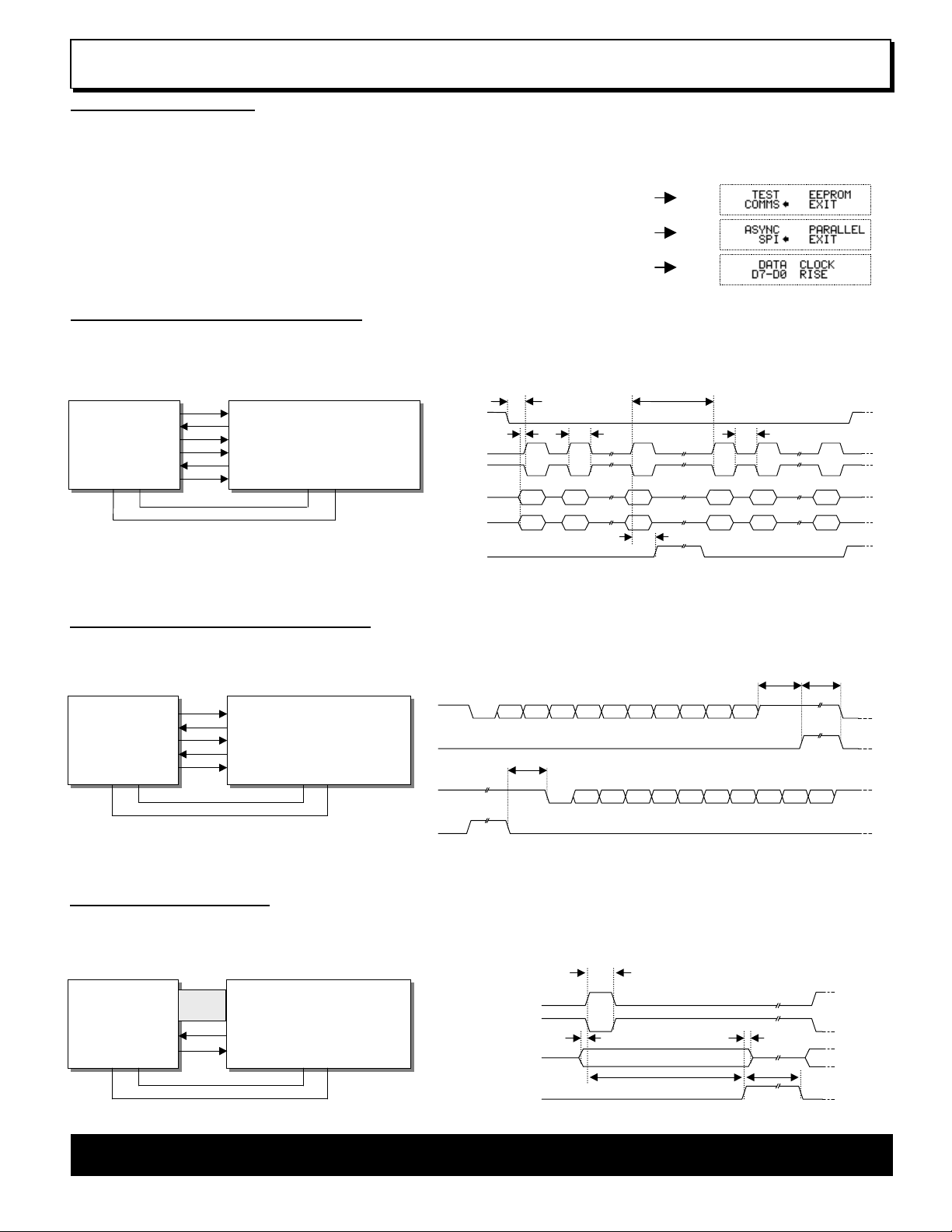
GU126x64D-K610A4 SETUP
The VFD module features two serial ports (synchronous & asynchronous) and a parallel port, all interfaces are TTL compatible. Interface
selection/set-up can be made using the single push button switch on the back of the module. Pressing the switch for the first time will display the
initial configuration menu. On each subsequent switch press the menu pointer will advance. The current menu item will be selected if the switch is
not pressed within 2 seconds.
To select the required interface, press the switch until the ‘COMMS’ item has been selected.
Wait 2 seconds for the communication menu to be displayed. Press the switch until the required
interface is selected. The factory default interface is SPI.
Wait another 2 seconds to display the related communication settings. The current configuration is
displayed first.
Interface selection example.
SYNCHRONOUS SERIAL COMMUNICATION
With synchronous communications enabled, data can be clocked into the VFD module using the rising or falling edge of SCK. This is selectable by
the push switch on the rear of the module, which also sets the data order. By default, data is clocked in on the rising edge with the most significant
bit sent first. The host must provide adequate delays for the module to process the data, these busy times are specified in the software command
section. Alternatively the host can monitor the MB (Module Busy) line.
SIN
SOUT
SCK
GU126x64D-K610A4
/SS
MB
/RES
VDD GNDVDDGND
HOST
SYSTEM
I/O
I/O
I/O
I/O
I/O
I/O
The /SS pin can be used as an enable pin if other devices are
connected to the serial line, and also allows byte synchronisation.
The use of the /SS line is optional, and can be permanently pulled
low if required.
/SS
SCK (RISING)
SCK (FALLING)
SIN (D7-D0)
SIN (D0-D7)
MB
>125ns
>65ns >125ns
D7
D6 D0 D7 D6 D0
D0
D1 D7 D0 D1 D7
TTL Synchronous serial communication.
tBUSY + 10us
>125ns
<10us
ASYNCHRONOUS SERIAL COMMUNICATION
The asynchronous communication speed and parity can be set with the push switch on the rear of the module, or with the ‘UART SETUP’
command. The default settings are 19200 baud with no parity. Again the host most provide adequate delays for the module to process the
command and data. The module busy line (MB) will go high when data is currently being processed.
<10us tBUSY
HOST
SYSTEM
TXD
RXD
I/O
I/O
I/O
RXD
TXD
GU126x64D-K610A4
HB
MB
/RES
VDD GNDVDDGND
The host busy line (HB) stops the module from sending data to
the host until the line falls. The use of the HB and MB lines are
RXD
MB
TTL Asynchronous serial communication from host system to VFD module.
TXD
HB
TTL Asynchronous serial communication from VFD module to host system.
D0 D7D1 D2 D3 D4 D4 D5 D6 PARITYSTART STOP
>2us
D0 D7D1 D2 D3 D4 D4 D5 D6 PARITYSTART STOP
optional, and can be connected together if not required.
PARALLEL COMMUNICATION
The 8 I/O lines can be configured as a slow parallel interface. Data on PA0-7 is clocked into the module with the Enable line, this can be set to
either a rising or falling edge trigger by the push switch on the back of the module. The host must keep the data stable for the time period indicated
in the timing diagram. The module busy line (MB) can be used in parallel communication mode.
>125ns
ENABLE (RISING)
ENABLE (FALLING)
D0 - D7
MB
Parallel Communication.
>250ns>125ns
DATA
<10us
tBUSY
HOST
SYSTEM
I/O
I/O
I/O
PA0-7
GU126x64D-K610A4
MB
ENABLE
VDD GNDVDDGND
NORITAKE ITRON VFD MODULES GU126x64D-K610A4
 Loading...