

Page 1

7503442.99.10.01
Montage- und Betriebsanleitung für Elektronik-Druckschalter 33D
Mounting and Operating Instructions for Electronic Pressure Switches 33D
Instructions pour le réglage du pressostat electronique 33D
Montaje e Instrucciones de Funcionamiento de los Presostatos Electrónicos 33D
Istruzioni di montaggio e funzionamento del Pressostato 33D
DIESES MERKBLATT SOLLTE AN EINER SICHEREN STELLE AUFBEWAHRT WERDEN
THIS LEAFLET SHOULD BE KEPT IN A SAFE PLACE FOR REFERENCE
CETTE NOTICE DOIT ÊTRE CONSERVÉE EN LIEU SÛR POUR UTILISATION EN CAS DE BESOIN
CONSERVAR ESTE DOCUMENTO COMO REFERENCIA EN LUGAR SEGURO
CONSERVARE IN UN LUOGO SICURO
1
1. Grundeinstellungen (Setup Mode)
Der Setup Mode wird durch langes (>4 sec) Betätigen der SET-Taste aktiviert. Im Setup Mode erscheint ein Menü, das
mit den Pfeiltasten durchgeblättert werden kann. Mit der SET-Taste wird ein Menüpunkt aufgerufen.
Mit der Tastenkombination ▼ + ▲kann zum Normalbetrieb zurückgesprungen werden. Falls mehr als 10 sec keine
Eingabe erfolgt, kehrt der Druckschalter ebenfalls zum Normalbetrieb zurück.
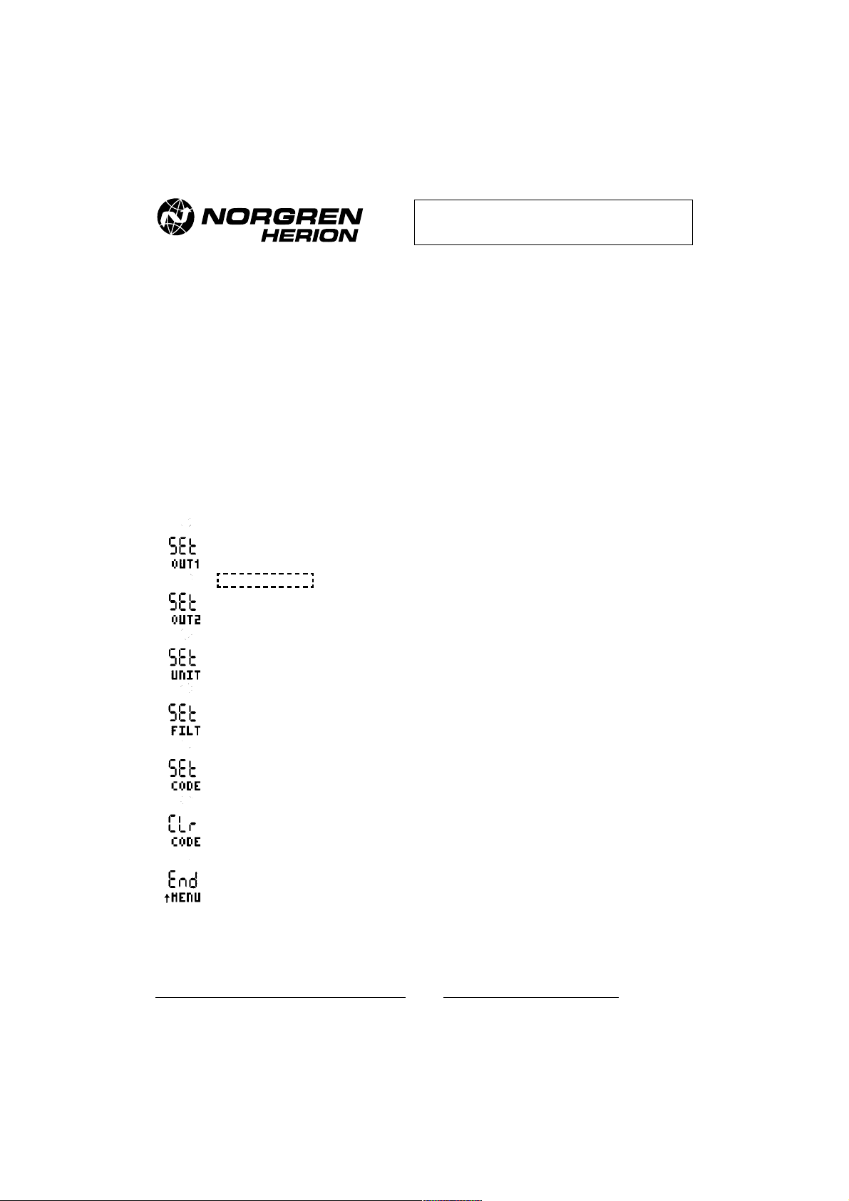
Das Setup Menü besteht aus folgenden Einträgen:
33D – Funktionen und Einstellungen
SET OUT1:
Ausgang 1 konfigurieren, (siehe 1.1).
SET OUT2:
Ausgang 2 konfigurieren, (siehe 1.1) (wird nur eingeblendet, wenn Ausgang 2 vorhanden ist).
SET UNIT:
Druckeinheit einstellen.
SET FILTER:
Filterzeitkonstante einstellen. Einstellbereich 3ms, 5ms, 10ms, 20ms, ...0.32 sec (Ausgangsseitige
Unterdrückung von Druckspitzen).
Set CODE:
Neuen CODE eingeben oder CODE ändern. Neue CODE-Kombination wird abgefragt und muss wiederholt
werden. Falls vorher schon eine Codierung aktiv war, muss zuerst der bestehende CODE eingegeben werden.
CLr CODE:
Löscht bestehenden CODE. Der bestehende CODE wird abgefragt (wird nur eingeblendet, wenn ein CODE
eingegeben worden ist).
End MENÜ:
Zurück zum Normalbetrieb.
* Siehe auch Rahmen Seite 2
Page 2
2
7503442.99.10.01
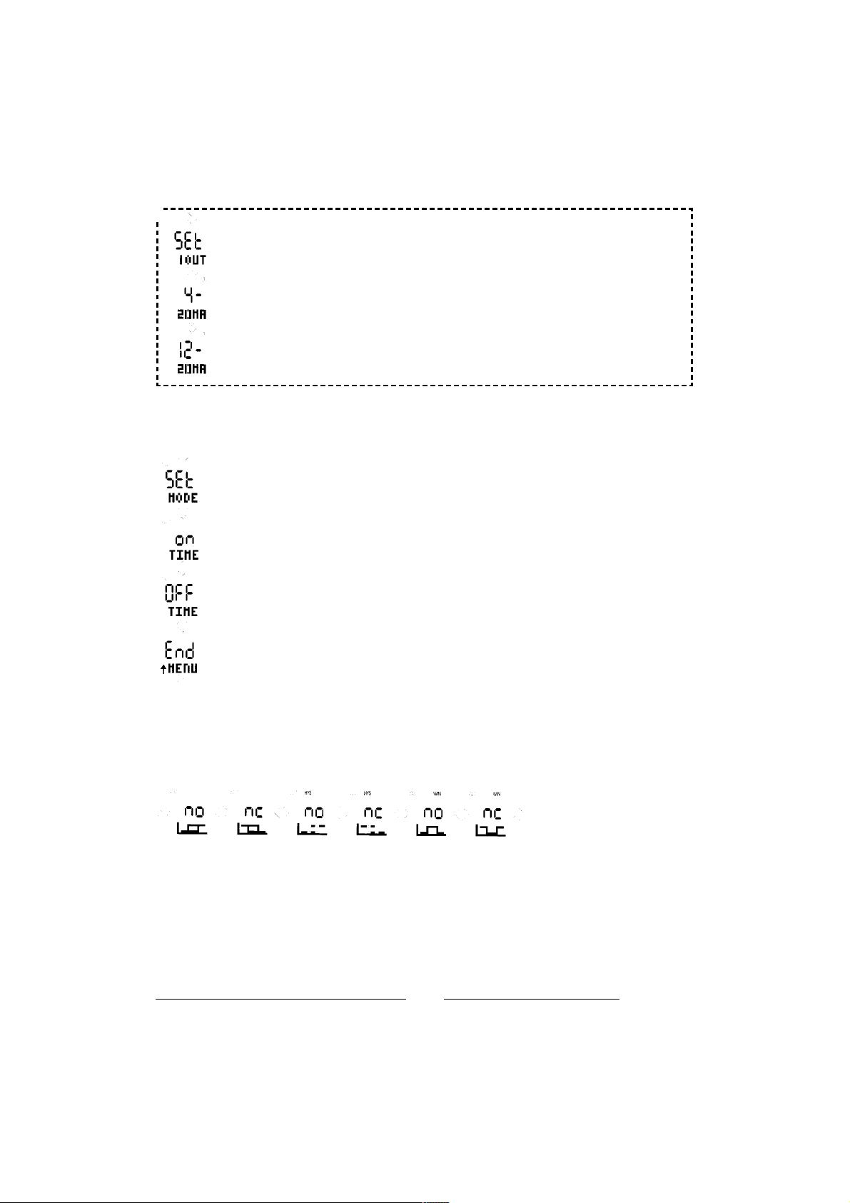
Bei der 33D-Variante 0863042 und ...46 (-1...+1 bar mit Analogausgang 4...20 mA) kann
der Anwender das Analogsignal 4...20 mA entweder auf 0...+1 bar (0 bar entspricht 4 mA) oder
aber auf -1...+1 bar (0 bar entspricht 12 mA) anpassen.
4...20 mA wird auf Druckbereich 0...+1 bar angepasst (0 bar = 4 mA).
4...20 mA wird auf Druckbereich -1...+1 bar angepasst (0 bar = 12 mA).
1.1 Schaltausgang konfigurieren
Mit dem Menüpunkt Set OUT1 (Set OUT2) wird folgendes Untermenü angezeigt:
(Der Indikator OUT1 bzw. OUT2 zeigt an, welcher Ausgang konfiguriert wird)
Set MODE:
Einstellen von Betriebsmode und Polarität des Schaltausgangs.
ON TIME:
Einschaltverzögerung einstellen. Der Einstellbereich reicht von 0.bis.20 sec in 10 ms Schritten.
OFF TIME:
Abschaltverzögerung einstellen. Der Einstellbereich reicht von 0 bis 20 sec in 10 ms Schritten.
End MENÜ:
Zurück zum Setup Menü.
Menüfolge
Mit der Set MODE Funktion wird die Betriebsart und die Ausgangspolarität festgelgt. (Mit den Pfeiltasten blättern und
mit der SET-Taste auswählen)
Normal-Betrieb Hysterese-Betrieb Fenster-Betrieb
Siehe Menüfolge unten
*
Siehe Menüfolge unten
Page 3
3
7503442.99.10.01
1.2 Power-Up Setup
Im Power-Up Setup sind Funktionen zusammengestellt, die vom Kunden nicht oder selten benötigt werden. Das
Power-Up Setup wird aktiviert, wenn beim Einschalten der Versorgungsspannung die Tastenkombination ▼ + ▲
betätigt wird.
Das Power-Up Setup Menü besteht aus folgenden Einträgen:
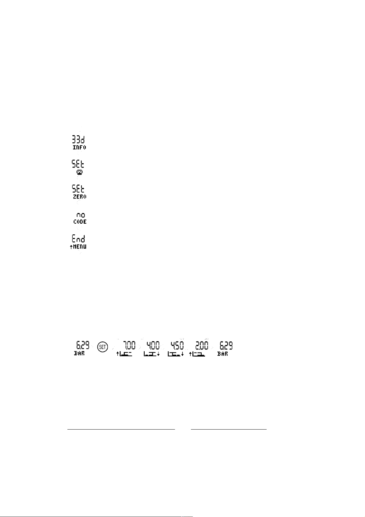
33d INFO:
Software Version und Seriennummer abfragen.
Set LIGHT:
Dauerbeleuchtung ein- (ON) oder ausschalten (OFF). Falls die Dauerbeleuchtung abgeschaltet ist,
erlischt die LCD Beleuchtung 10 sec nach dem letzten Tastendruck.
Set ZERO:
Nullpunkt Unterdrückung einstellen. Falls das Drucksignal kleiner als der eingestellte Wert ist, wird im
LCD Null angezeigt. Damit lassen sich Digit Sprünge im Nullpunkt und Nullpunkt driften ausblenden.
Der Grenzwert wird in %FS eingestellt.
no CODE:
Damit kann ein Code mit Hilfe der Master-Code-Kombination (Seite 5) entfernt werden (wenn 33D
codiert ist). Die Menüfunktion „SET CODE“ kann entfernt, bzw. wieder aktiviert werden.
End MENÜ:
Zurück zur Standard-Anzeige.
2. Schaltpunkte einstellen (SET-Taste kurz drücken)
Mit SET-Taste wird der Einstellwert bestätigt u. zum nächsten Schaltpunkt gesprungen. Falls mehr als 12 Sek. keine
Eingabe erfolgt, kehrt der Druckschalter zum Normalbetrieb zurück, ohne dass der momentan dargestellte Einstellwert
gespeichert wird.
Mit der Tastenkombination ▼ + ▲kann die Einstellfunktion ohne Speichern beendet werden.
2.1. Standard-Betriebsart:
Je nach eingestellter Polarität (nc/no, siehe Setup) wird das Schaltdiagramm dargestellt, wobei die momentan einstellbare Schaltflanke blinkend dargestellt wird. Der Schaltpunkt wird mit dem Pfeil nach oben ▲ (Ausgang aktiviert, steigende Flanke) markiert. Der Rückschaltpunkt wird analog hierzu mit dem fallenden Pfeil ▼ gekennzeichnet.
SET-Taste drücken: Der eingestellte Wert wird gespeichert und es wird zum nächsten Einstellwert weiter geschaltet.
Beispiel. - Bild 1: Schaltausgang 1 im Standard-Mode mit (n.o.), Schaltausgang 2 im Standard-Mode (n.c.)
Page 4
4
7503442.99.10.01
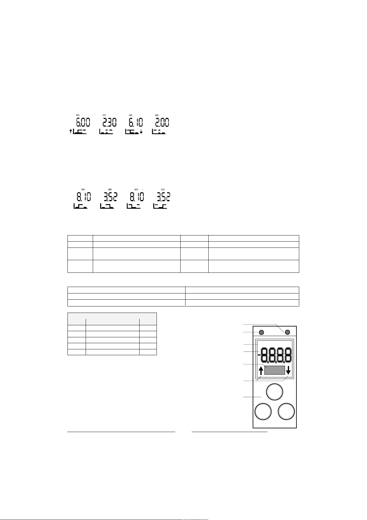
2.2 Hysterese-Betriebsart:
Beim Einstellen des Schaltpunkts blinkt je nach Betriebsart die Einschaltflanke (Betriebsart no) oder die Abschaltflanke
(Betriebsart nc). Beim Einstellen der Schalthysterese blinkt das Hysteresediagramm.
Beispiel. - Bild 2: Schaltausgang 1 no, Schaltausgang 2 nc
2.3 Fenster Betriebsart
In dieser Betriebsart wird mit Schaltpunkt und Rückschaltpunkt ein Druckbereich definiert. Befindet sich der angelegte
Druck innerhalb diesem "Fenster", wird der Schaltausgang aktiviert (Polarität no) oder abgeschaltet (Polarität nc). Je
nach eingestellter Polarität (nc/no, siehe Setup) wird das Hysteresediagramm dargestellt, wobei die momentan einstellbare Schaltflanke blinkend dargestellt wird.
Beispiel. - Bild 3: Schaltausgang 1 no, Schaltausgang 2 nc
3. Fehler- und Warnmeldungen
LO VOLT Versorgungsspannung zu gering LO TEMP Temp. Signal zu gering oder Sensor defekt
HI PRES Drucksignal zu groß oder Messzelle defekt CALI Druckschalter nicht richtig kalibriert
LO PRES Drucksignal zu klein oder Messzelle defekt ESET SETUP-Einstellungen für Filter, Einheit, Code fehler-
haft
HI TEMP Temp. Signal zu hoch oder Sensor defekt ESH1 (2) SETUP-Einstellungen Ausgang1 (2) fehlerhaft
(Mode, On/Off Time)
4. Auslieferungszustand Platz für Ihre Einstellungen
– Anzeige bar
– Schaltmodus Standard, n. o.
– Anzugs- /Abfallverzögerung 0 sek.
LED Schaltausgang 2 (optional)
LED Schaltausgang 1
Indikatoren für Betriebsmodi
Dot-Matrix Universal-Anzeigefeld
Anzeigehilfe während Einstellung von
Schalt- und Rückschaltwert
Bedienfeld mit 3 Tasten
4stelliges 7-Segment-Anzeigefeld
Frontansicht – Bedien- und Anzeigeelemente
Elektroanschluss M 12 x 1
Stecker Signal Kabel
1 + UB braun
2 Out 2 (PNP) / analog 4 – 20 mA weiss
3 0 Volt blau
4 Out 1 (PNP) schwarz
5 PE grau
OUT1 HYS WIN
OUT2
SET
▼
▼
Page 5
5
7503442.99.10.01
STANDARD-DRUCKANZEIGE
Menüpunkt-Auswahl und
Einstellungen bestätigen
Blättern im Menü und Werte
erhöhen
Blättern im Menü und Werte
reduzieren
* no = Schaltausgang bei Atmosphäre (0 bar) = 0 V
** nc = Schaltausgang bei Atmosphäre (0 bar) = + UB
*** Variante 33D für Vakuum und mit Analogausgang 4 bis 20 mA (0863042 und 0863046) kann wie folgt
programmiert werden:
a) 4 bis 20 mA angepasst auf Bereich-1 bis +1 bar (0 bar = 12 mA)
b) 4 bis 20 mA angepasst auf Bereich 0 bis +1 bar (0 bar = 4 mA)
Mastercode 1
Mastercode 2
33D ist nicht kodiert:
Menüfunktion „SET CODE“
entfernen / aktivieren.
33D ist kodiert:
Code kann gelöscht werden.
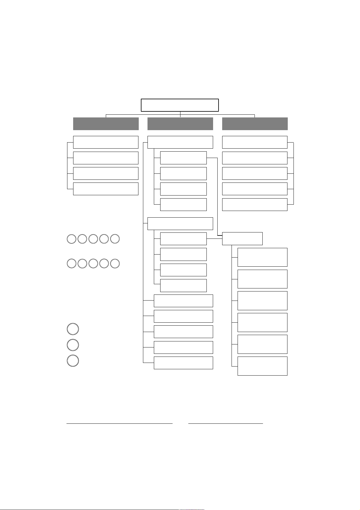
33D – Funktionen und Einstellungen
****
Schaltpunkte
(SET) kurz drücken
▼
Schaltpunkt OUT1
mit ▲ ▼ einstellen
mit (SET) festlegen
Rückschaltpunkt OUT1
mit ▲ ▼ einstellen
Rückschaltpunkt OUT2
SET
▼
mit (SET) festlegen
Schaltpunkt OUT2
mit ▲ ▼ einstellen
mit (SET) festlegen
mit ▲ ▼ einstellen
mit (SET) festlegen
▼
▼
▼
▼
SET
SET
SET
▼
SET
▼
▼
Setup-Menü
(SET) > 4 sek. drücken
▼ ▼
Set OUT1
mit (SET) auswählen
Konfiguration Ausgang 1
Set MODE
mit (SET) auswählen
on TIME
mit (SET) auswählen
Einschaltverzögerung einstellen mit ▲ ▼
off TIME
mit (SET) auswählen
Abschaltverzögerung einstellen mit ▲ ▼
END MENÜ
zurück ins Setup-Menü
Set OUT2 ***
mit (SET) auswählen
Konfiguration Ausgang 2
Set MODE
mit (SET) auswählen
on TIME
mit (SET) auswählen
Einschaltverzögerung einstellen mit ▲ ▼
off TIME
mit (SET) auswählen
Abschaltverzögerung einstellen mit ▲ ▼
END MENÜ
zurück ins Setup-Menü
Set UNIT
mit (SET) auswählen
(BAR, PSI, MPA) mit ▲ ▼
Set Filter
mit (SET) auswählen
Druckspitzen-Dämpfung mit ▲ ▼
Set CODE
Zugriffs-Schutz programmieren
(5 Tastenfolgen)
Clear CODE
mit (SET) auswählen
Zugriffs-Schutz aufheben
END MENÜ
mit (SET) auswählen
zurück in Standard-Anzeige
Power-UP Setup
▲ + ▼ während Spannungszufuhr
33D INFO
mit (SET) auswählen
Serie und Softwarestand
Set LIGHT
mit (SET) auswählen
Displaybeleuchtung ein/aus
Set ZERO
mit (SET) auswählen
Nullpunktunterdrückung
no Code ****
mit (SET) auswählen
mit Mastercode 1 u. 2 Zugriffsschutz entfernen
END MENÜ
mit (SET) auswählen
zurück in Standard-Anzeige
Set MODE
mit (SET) auswählen
no *
OUT 1/2 Standard Mode
n. o. mit (SET) bestätigen
▲ ▼ weiter
mit
nc **
OUT 1/2 Standard Mode
n. c. mit (SET) bestätigen
▲ ▼ weiter
mit
no *
OUT 1/2 Hysterese Mode
n. o. mit (SET) bestätigen
▲ ▼ weiter
mit
nc **
OUT 1/2 Hysterese Mode
n. c. mit (SET) bestätigen
▲ ▼ weiter
mit
no *
OUT 1/2 Windows Mode
n. o. mit (SET) bestätigen
▲ ▼ weiter
mit
nc **
OUT 1/2 Windows Mode
n. c. mit (SET) bestätigen
▲ ▼ weiter
mit
Page 6
6
7503442.99.10.01
Mounting and Operating Instructions for Electronic Pressure Switches 33D
THIS LEAFLET SHOULD BE KEPT IN A SAFE PLACE FOR REFERENCE
1. Standard settings (Setup MENU)
The Setup MENU is activated by pressing the SET button for a minimum of 4 seconds. A sub-menu appears and the
individual functions can be selected by using the arrow buttons. For configuration within a function please press the
corresponding SET button. Pressing both arrow buttons simultaneously or inactivity >10 sec. will cause the return to
the standard mode without any changes.
The Setup MENU comprises the following functions:
33D – Functions and Settings
SET OUT1:
Output 1 configuration (see 1.1.).
SET OUT2:
Output 2 configuration (see1.1.) (only applicable for 33D version with 2 outputs)
SET UNIT:
Selection of pressure unit
SET FILTER:
Configuration of filter time. Setting ranges 3ms, 5ms, 10ms, 20ms,….0.32sec (Suppression of output
pressure peaks)
Set CODE:
Setting of a new code or changing a code. A new code will be checked and must be repeated.
For changing an existing code this one has to be entered first before setting a new code.
CLr CODE:
Deletes an existing code. Entering of this code prior to deleting is necessary.
End MENÜ:
Storing and back to Operating Display (indication of system pressure)
* Pls. see table page 2
Page 7

7
7503442.99.10.01
The 33D versions 0863042 and ...46 (-1...+1 bar / analogue output) provide the possibility to
either adjust the analog signal to 0...+1 bar (0 bar = 4 mA) or to –1...+1 bar (0 bar = 12 mA)
4...20 mA can be adjusted to range 0...+1 (0 bar = 4 mA)
4...20 mA can be adjusted to range –1...+1 bar (0 bar = 12 mA)
1.1. Configuration of the output signals OUT1 / OUT2 (Configuration MENU)
By pressing the SET button in menu SET OUT 1 (SET OUT 2) the belowmentioned functions will be available for individual configuration:(The indicator OUT 1 resp. OUT 2 in the top line of the display will show which signal is being configurated)
Set MODE:
Setting of the Operating MODE and polarity of the output signal.
(See 1.2. sequence of menu below)
ON TIME:
Setting of switch-on delay. Setting range 0…20 sec in steps of 10ms
OFF TIME:
Setting of the switch-off delay. Setting range 0…20 sec in steps of 10ms
End MENU:
Storing and back to Operating Display (indication of system pressure)
Sequence of settings within the SET MODE:
In this mode the operating mode and polarity will be determined. Selection by pressing the arrow buttons and confirmation by SET button)
Standard Mode Hysteresis Mode Window Mode
Pls. see sequence of settings below.
*
Page 8

8
7503442.99.10.01
1.2 System Configuration MENU
In this MENU basic functions are provided. Activation by pressing the arrow buttons ▼ + ▲ simultaneously during the
power-on procedure.
The following functions are provided:
33d INFO:
Information of the software version und Serial number.
Set LIGHT:
Switch-ON or OFF of the permanent illumination. The OFF-status however still provides illumination of
the display during the course of any operation and ceases to light automatically after 10 seconds of
inactivity.
Set ZERO:
The pressure indication in the zero point can be suppressed in % FS, i.e. 1% FS of 100 ( = 1 bar)
means, that the pressure indication up to 1 bar is actually indicated as 0 bar. Flickering digits on the
display (in the zero point) can be avoided.
no CODE:
This function allows the code elimination with the help of the master code combination (page 10).
The „set code“ function can either be deleted or activated.
End MENU:
Storing and back to Operating Display (indication of system pressure)
2. Setting of the Switching points
Press SET once for the switching point of OUT 1 (OUT 2) and choose your set value by using the arrow buttons. Press
SET for confirmation and continue with the reset point of OUT 1 (OUT 2). In case of inactivity for more than 12
seconds the display returns to the operating display without storing the set values. By pressing both arrow buttons
simultaneously this function can be terminated immediately and the display returns to the operating display wihout
storing the settings.
2.1. Standard-MODE:
Depending on the chosen polarity (n.c / n.o, see setup) the corresponding switching diagram appears on the display
and the presently adjustable switching flank blinks. The switching point is marked by the arrow pointing upwards
(Switching OUT activated = rising flank)
Accordingly the reset point is marked by the arrow pointing downwards (Switching OUT inactivated = falling flank)
Pressing the SET button stores the setting and makes the display to switch to the next step.
Picture 1: Switching OUT 1 in the standard mode with (n.o.), switching OUT 2 in the standard mode (n.c.)
Page 9

9
7503442.99.10.01
2.2 Hysteresis-MODE:
During the course of the set point setting either the switch-on flank (n.o status) or the switch-off flank (n.c status) will
blink, depending on the operating mode. When setting the hysteresis mode consequently the hysteresis mode will
blink. Depending on the set polarity (n.c. / n.o. see setup) the hysteresis diagram will appear on the display with the
adjustable switching flank blinking.
Picture 2: Switching OUT 1n.o., switching OUT 2 n.c.
2.3 Window MODE:
This operating mode provides the definition of a switching point and a reset point within a pressure range. In case the
prevailing pressure is within this "window”, the switching out will be activated (polarity n.o.) or inactivated (polarity
n.c.)
Picture 3: Switching OUT 1 n.o., switching OUT n.c.
3. Error- and warning messages:
LO VOLT Supply voltage too low LO TEMP Temp. Signal too low or sensor defect
HI PRES Pressure signal too high or sensor defekt CALI Pressure switch not properly calibrated
LO PRES Sensor defect ESET Pressure switch not properly
calibrated
HI TEMP Temp. Signal too high or sensor defect ESH1 (2) SETUP settings OUT 1 (2)
for mode, on/off time not correct
4. Despatch settings Your settings
– Display bar
– Switching mode Standard n. o.
– Switch on/off delay 0 sec.
LED Output 2 (optional)
LED Output 1
Indication for Operating MODE
Dot-Matrix for additional informations
Indication during adjusting setpoint and
resetpoint
Keypad with 3 buttons
7-segment display (4 digits)
Function keys and display
Electrical connection M 12 x 1
Pin Signal Cable
1 + UB brown
2 Out 2 (PNP) / analog 4 to 20 mA white
3 0 Volt blue
4 Out 1 (PNP) black
5 PE grey
OUT1 HYS WIN
OUT2
SET
▼
▼
Page 10

10
7503442.99.10.01
OPERATING DISPLAY
Menu selection and confirmation
of settings
Browsing within menu and
increasing of values
Browsing within menu and reducing of values
* no = output signal at atmosphere (0 bar) = 0 V
** nc = output signal at atmosphere (0 bar) = +U
B
*** Variation 33D for vacuum and with analogue signal 4 to 20 mA (0863042 and 0863046) can be programmed
as follows: a) 4 to 20 mA adapted to range -1 to +1 bar (0 bar = 12 mA)
b) 4 to 20 mA adapted to range 0 to +1 bar (0 bar = 4 mA)
Mastercode 1
Mastercode 2
– 33D is not coded: Menu function „SET
CODE“ can be deleted/activated.
– 33D is coded: Code can be deleted.
Operating instructions
****
Indication of system pressure
SET
▼
▼
SET
SET
▼
▼
SET POINTS
press (SET)
Set point OUT1
adjust with ▲ ▼
confirm with (SET)
Reset point OUT1
adjust with ▲ ▼
confirm with (SET)
Set point OUT2
adjust with ▲ ▼
confirm with (SET)
Reset point OUT2
adjust with ▲ ▼
confirm with (SET)
▼
SET
▼
▼
▼
SET
▼
Setup-Menu
press (SET) > 4 sec.
▼ ▼
Set OUT1
select with (SET)
configuration of output 1
Set MODE
select with (SET)
on TIME
select with (SET)
adjust switch on delay with ▲ ▼
off TIME
select with (SET)
adjust switch on delay with ▲ ▼
END MENÜ
back to Setup-MENU
Set OUT2 ***
select with (SET)
configuration of output 2
Set MODE
select with (SET)
on TIME
select with (SET)
adjust switch on delay with ▲ ▼
off TIME
select with (SET)
adjust switch on delay with ▲ ▼
END MENU
back to Setup-MENU
Set UNIT
select with (SET)
(BAR, PSI, MPA) with ▲ ▼
select
Set Filter
select with (SET)
pressure peak damping with ▲ ▼
Set CODE
Access protection
determine by pressing 5 buttons of your choice
Clear CODE
select with (SET)
delete access protection
END MENÜ
select with (SET)
back to operating display
System Configuration MENU
▲ + ▼ during power-on procedure
33D INFO
select with (SET)
Series and Software-Release No.
Set LIGHT
select with (SET)
Display illumination on/off
Set ZERO
select with (SET)
Zero point suppression
no Code ****
select with (SET)
delete with Mastercode 1 and 2
END MENÜ
select with (SET)
back to Operating Display
Set MODE
select with (SET)
no *
OUT 1/2 Standard Mode
confirm n. o. with (SET)
OUT 1/2 Standard Mode
confirm n. c. with (SET)
OUT 1/2 Hysterese Mode
confirm n. o. with (SET)
OUT 1/2 Hysterese Mode
confirm n. c. with (SET)
OUT 1/2 Windows Mode
confirm n. o. with (SET)
OUT 1/2 Windows Mode
confirm n. c. with (SET)
next step with
nc **
next step with
no *
next step with
nc **
next step with
no *
next step with
nc **
next step with
▲ ▼
▲ ▼
▲ ▼
▲ ▼
▲ ▼
▲ ▼
Page 11

11
7503442.99.10.01
Instructions pour le réglage du pressostat electronique 33D
CETTE NOTICE DOIT ÊTRE CONSERVÉE EN LIEU SÛR POUR UTILISATION EN CAS DE BESOIN
1. Réglages standard (Mode Setup)
Pour activer le mode Setup, maintenir la touche SET appuyée pendant au moins 4 secondes. Un sous-menu apparaît.
Sélectionner la fonction désirée en utilisant les flèches. Le choix d’une fonction s’opère en maintenant la touche SET
correspondante appuyée. Si vous appuyez sur les deux flèches en même temps ou si vous laissez >10 sec. s’écouler
avant d’appuyer sur une des flèches, vous revenez en mode standard.
Le mode Setup comprend les fonctions suivantes :
33D – Fonctions et réglages
SET OUT1:
Configuration de la sortie 1 (voir 1.1.).
SET OUT2:
Configuration de la sortie 2 (voir 1.1.) (ne concerne que la version 33D avec 2 sorties)
SET UNIT:
Sélection de l’unité de pression
SET FILTER:
Configuration de la bande passante. Possibilités de réglage 3ms, 5ms, 10ms, 20ms,….0.32sec
(Suppression de la lecture des pointes de sortie)
Set CODE:
Entrée d’un nouveau code d’accès ou changement du code d’accès. Entrer une nouvelle fois le code pour
le valider.
Pour changer un code existant, il est nécessaire tout d’abord de le rentrer.
CLr CODE:
Suppression d’un code existant. Il est nécessaire dans un premier temps de rentrer le code existant pour
pouvoir ensuite le supprimer.
End MENU:
Mémorisation et retour à l’affichage normal (indication de la pression du système)
* Voir page 12
Page 12

12
7503442.99.10.01
Les versions 33D références 0863042 et ...46 (-1...+1 bar / sortie analogique) offrent la possibilité de régler le signal analogique de 0...+1 bar (0 bar = 4 mA) ou de –1...+1 bar (0 bar = 12 mA)
4...20 mA peut être réglé de 0...+1 (0 bar = 4 mA)
4...20 mA peut être réglé –1...+1 bar (0 bar = 12 mA)
1.1. Configuration des signaux de sortie de commutation OUT1 / OUT2
Si vous appuyez sur la touche SET en mode SET OUT 1 (SET OUT 2), les fonctions décrites ci-dessous vont apparaître,
vous permettant la configuration personnalisée de votre appareil:(OUT 1 ou OUT 2 s’affiche sur la ligne supérieure de
l’écran pour indiquer quelle sortie est en train d’être configurée)
Set MODE:
Réglage du mode d’utilisation et de la polarité du signal de sortie.
(Voir exemple de séquences de réglage en bas de page)
ON TIME:
Réglage de la temporatisation d’appel. Réglage de 0…20 sec par pas de 10ms
OFF TIME:
Réglage de la temporisation de coupure. Réglage de 0…20 sec par pas de 10ms
End MENU:
Mémorisation et retour à l’affichage normal (indication de la pression du système).
Exemple de séquences de réglage en mode SET
Ce mode permet de déterminer le mode de service d'utilisation et la polarité du signal de sortieen appuyant sur la
flèche et en confirmant avec SET.
Mode standard Mode Hystérésis Mode fenêtre
Voir exemple de séquence de réglage en bas de page.
*
Voir exemple de séquence de réglage en bas de page.
Page 13

13
7503442.99.10.01
1.2 Mode configuration du système
Ce mode permet d’accèder aux fonctions de base de l’appareil. Presser les flèches ▼ + ▲ simultanément à la mise
sous-tension.
Fonctions disponibles :
33d INFO:
Indique la version du programme et le numéro de série de l’appareil.
Set LIGHT:
Activation (ON) ou désactivation (OFF) du rétro éclairage. Même en mode désactivé (OFF), l’écran
restera allumé si l’appareil est en cours de fonctionnement et s’éteindra seul automatiquement après 10
secondes de non fonctionnement.
Set ZERO:
L’indication de la pression au point 0 peut être supprimée en %age de la pleine échelle : 1% de la pleine
échelle de 100 ( = 1 bar) signifie qu’en fait jusqu’à 1 bar, la pression est indiquée comme étant égal À 0
bar. Il est possible d’éviter le clignotement de l’écran (au point zéro).
no CODE:
Cette fonction permet de supprimer le code à l’aide du mot de passe (page 11).
La fonction „set code“peut être activée ou désactivée.
End MENU:
Mémorisaton et retour à l’affichage normal (indication de la presssion du système)
2. Réglage des points de commutation
Appuyer une fois sur la touche SET pour régler le point de commutation sortie 1 (OUT 1) ou sortie 2 (OUT 2). Choisir la
valeur désirée à l’aide des flèches. Confimer en appuyant sur la touche SET. Continuer avec le point de retour OUT 1
(OUT 2). Si après 12 secondes vous n’avez activé aucune touche, l’écran revient en affichage normal sans enregistrer
les valeurs de réglage. Le même résultat peut être obtenu en appuyant simultanément sur les deux flèches.
2.1. Mode Standard
Suivant la polarité choisie (n.f / n.o, voir setup), le diagramme de commutation correspondant apparaît sur l’écran et le
point de réglage du diagramme clignote. Le point de commutation est indiqué par une flèche montante (sortie (OUT)
activée = barre montante).
Le point de réinitialisation est indiqué par une flèche descendante (point de sortie de commutation (OUT) inactivé =
barre descendante)
Appuyer sur la touche SET pour mémoriser le réglage et passer l’étape suivante.
Exemple : Sortie OUT 1 en mode standard (n.o.), sortie OUT 2 en mode standard (n.f.)
Page 14

14
7503442.99.10.01
2.2 Mode hystérésis :
Lors du réglage des seuils, les barres d’appel (n.o ) ou de coupure(n.c ) se mettent à clignoter selon le mode de service. Lorsque vous réglez le mode hystérésis, celui-ci clignote. Selon la polarité choisie (n.c. / n.f. voir setup) le diagramme d’hystérésis s’affiche sur l’écran et les barres de réglage clignotent.
Exemple 2: commutation OUT 1n.o., commutation OUT 2 n.f.
2.3 Mode fenêtre :
Ce mode de service permet de définir un point de commutation et un point de réinitialisation à l’intérieur d’une plage de
pression. Tant que la pression se situe à l’intérieur de cette “fenêtre”, le point de sortie de commutation sera activé
(polarité n.o.) ou inactivé (polarité n.f.)
Exemple 3: commutation OUT 1 n.o., commutation OUT 2 n.f.
3. Messages d’erreur et affichage de défauts fonctionnels:
LO VOLT Tension d’alimentation trop basse LO TEMP Signal de temp. trop bas ou capteur défecteux
PRES
Signal de pression trop élevé ou capteur défectueux
CALI Mauvais calibrage du pressostat
LO PRES Défaut du capteur ESET Setup: Mauvais calibrage du set filter,
calibrated unit, code
HI TEMP Signal de temp.trop élevé ou capteur défecteux ESH1 (2) réglage SETUP OUT 1 (2)
mode temporisation appel/coupure non correct
4. Réglages Pour noter vos réglages
– Afffichage en bar
– Mode de commutation standard n. o.
– Temporisation appel/coupure 0 sec.
LED sortie 2 (en option)
LED sortie 1
Indication du mode d'utilisation
Affichage du diagramme de
commutation
Indication de la phase d’initialisation
ou de réinitialisation
Clavier 3 touches
Affichage 7-segments (4 digits)
Fonctions clés et affichage
Connexion électrique M 12 x 1
Connecteur Signal Cable
1 + UB marron
2 Out 2 (PNP) blanc
analogue 4 – 20 mA
3 0 Volt bleu
4 Out 1 (PNP) noir
5 PE gris
OUT1 HYS WIN
OUT2
SET
▼
▼
Page 15

AFFICHAGE ECRAN
15
7503442.99.10.01
Sélection du menu et confirmation des réglages
Déplacement dans le menu et
augmentation des valeurs
Déplacement dans le menu et
réduction des valeurs
* no = signal de sortie à l’atmosphère (0 bar) = 0 V
** nf = signal de sortie à l’atmosphère (0 bar) = +U
B
*** Modèle 33D pour le vide et avec signal analogiquel 4 à 20 mA (0863042 et 0863046). Possibilité de programmation
comme suit : a) 4 à 20 mA adapté à la plage -1 à +1 bar (0 bar = 12 mA)
b) 4 à 20 mA adapté à la plage 0 à +1 bar (0 bar = 4 mA)
Code d’accès 1
Code d’accès 2
– 33D sans codage: entrer dans le menu
codage avec “SET CODE“ pour activer ou
désactiver le code.
– 33D codé : possibilité de désactiver le
code
Tableau récapitulatif des différentes possibilités de réglages
****
Indication de la pression du système
Réglage des seuils
appuyer sur la touche (SET)
▼
Réglage sortie de commutation OUT1
régler avec ▲ ▼
valides avec (SET)
Réinitialisation sortie de commutation OUT1
▼
régler avec ▲ ▼
valides avec (SET)
Réglage sortie de commutation OUT2
régler avec ▲ ▼
valides avec (SET)
Réinitialisation sortie de commutation OUT2
régler avec ▲ ▼
valides avec (SET)
▼
SET
▼
▼
▼
SET
SET
SET
▼
SET
▼
▼
Setup-Menu
presser (SET) > 4 sec.
▼ ▼
Set OUT1
sélectionner avec (SET)
configuration sortie de commutation 1
Set MODE
sélectionner avec (SET)
on TIME
sélectionner avec (SET)
régler avec ▲ ▼
off TIME
sélectionner avec (SET)
régler avec ▲ ▼
END MENU
retour au menu setup
Set OUT2
sélectionner avec (SET)
configuration de la sortie 2
Set MODE
sélectionner avec (SET)
on TIME
sélectionner avec (SET)
régler avec ▲ ▼
off TIME
sélectionner avec (SET)
régler avec ▲ ▼
END MENU
retour au menu setup
Set UNIT
sélectionner avec (SET)
(BAR, PSI, MPA) avec ▲ ▼
sélectionner
Set Filter
sélectionner avec (SET)
réglage temps d'amortissement avec ▲ ▼
Set CODE
protection d'accèss
combinaison de touches (5 fois)
Clear CODE
sélectionner avec (SET)
suppression de la protection
END MENÜ
sélectionner avec (SET)
retour à l'affichage standard
System Configuration MENU
presser▲ + ▼ pendant la mise sous tension
33D INFO
sélectionner avec (SET)
N° de série et version du programme
Set LIGHT
sélectionner avec (SET)
illumination de l'écran activée/non-activée
Set ZERO
sélectionner avec (SET)
suppression du point zéro
no Code ****
sélectionner avec (SET)
suppression avec le mot de passe 1 et 2
END MENU
sélectionner avec (SET)
retour à l'affichage standard
Set MODE
sélectionner avec (SET)
no *
OUT 1/2 Standard Mode
confirmer n.o. avec (SET)
étape suivante avec
OUT 1/2 Standard Mode
confirmer n.c. avec (SET)
étape suivante avec
OUT 1/2 Hysterese Mode
confirmer n.o. avec (SET)
étape suivante avec
OUT 1/2 Hysterese Mode
confirmer n.c. avec (SET)
étape suivante avec
OUT 1/2 Windows Mode
confirmer n.o. avec (SET)
étape suivante avec
OUT 1/2 Windows Mode
confirmer n.c. avec (SET)
étape suivante avec
▲ ▼
nc **
▲ ▼
no *
▲ ▼
nc **
▲ ▼
no *
▲ ▼
nc **
▲ ▼
Page 16

16
7503442.99.10.01
FUNCIONAMIENTO DEL DISPLAY
Instrucciones de funcionamiento
Montaje e Instrucciones de Funcionamiento de los Presostatos Electrónicos 33D
CONSERVAR ESTE DOCUMENTO COMO REFERENCIA EN LUGAR SEGURO
Indicación del sistema de presión
PUNTOS DE AJUSTE
pulsar (SET)
▼
Ajuste SALIDA 1
ajustar con ▲ ▼
confirmar con (SET)
Reinicializar SALIDA 1
ajustar con ▲ ▼
confirmar con (SET)
Ajuste SALIDA 2
ajustar con ▲ ▼
confirmar con (SET)
Reinicializar SALIDA 2
ajustar con ▲ ▼
confirmar con (SET)
MENU-Setup
pulsar (SET) > 4 seg.
▼ ▼
Set OUT1
seleccionar con (SET)
Configuración de la salida 1
Set MODE
seleccionar con (SET)
on TIME
seleccionar con (SET)
Ajustar tiempos con ▲ ▼
off TIME
seleccionar con (SET)
Ajustar tiempos con ▲ ▼
END MENÜ
volver al MENU Setup
Set OUT2 ***
seleccionar con (SET)
Configuración salida 2
Set MODE
seleccionar con (SET)
on TIME
seleccionar con (SET)
Ajustar tiempos con ▲ ▼
off TIME
seleccionar con (SET)
Ajustar tiempos con ▲ ▼
END MENU
volver al MENU Setup
Set UNIT
seleccionar con (SET)
(BAR, PSI, MPA) con ▲ ▼
Seleccionar
Set Filter
seleccionar con (SET)
Amortiguación puntas de presión ▲ ▼
Set CODE
código de protección
Determinar pulsando 5 botones
Clear CODE
seleccionar con (SET)
Borra el código de protección
END MENÜ
seleccionar con (SET)
Vuelve el display a su función de indicación
MENU de configuración del sistema
▲ + ▼ con el equipo en funcionamiento
Iluminación del display on/off
Borrar con el Código Maestro 1 y 2
Vuelve el display a su función de indicación
Set MODE
seleccionar con (SET)
33D INFO
seleccionar con (SET)
Serie y Software No.
Set LIGHT
seleccionar con (SET)
Set ZERO
seleccionar con (SET)
Supresión del punto cero
no Code ****
seleccionar con (SET)
END MENÜ
seleccionar con (SET)
NA *
SALIDA 1/2 Modo Standard
confirmar n. o. con (SET)
paso siguiente con
NC **
SALIDA 1/2 Modo Standard
confirmar n. c. con (SET)
paso siguiente con
NA *
OUT 1/2 Modo Histéresis
confirmar n. o. con (SET)
paso siguiente con
NC **
OUT 1/2 Modo Histéresis
confirmar n. c. con (SET)
paso siguiente con
NA *
OUT 1/2 Modo Ventana
confirmar n. o. con (SET)
paso siguiente con
NC **
OUT 1/2 Modo Ventana
confirmar n. c. con (SET)
paso siguiente con
▲ ▼
▲ ▼
▲ ▼
▲ ▼
▲ ▼
▲ ▼
Page 17

17
7503442.99.10.01
SET
Selección del Menu y
confirmación de ajustes
Ver menú e incrementar valores
Ver menú y reducir valores
* NA = señal de salida a la atmósfera (0 bar) = 0 V
** NC = señal de salida a la atmósfera (0 bar) = +U
B
*** Variante del 33D. (0863042 y 0863046) Puede programarse para vacío y señal analógica 4 a 20 mA
de la siguiente forma: a) 4 a 20 mA para la gama -1 a +1 bar (0 bar = 12 mA)
b) 4 a 20 mA para la gama 0 a +1 bar (0 bar = 4 mA)
Código Maestro 1
Código Maestro 2
33D no codificado:
El menu función „SET CODE“ puede ser
desactivado/activado.
33D codificado:
El código puede ser desactivado.
****
Instrucciones de funcionamiento
Conexión eléctrica M 12 x 1
Conector Señal Cable
1 + UB marrón
2 Out 2 (PNP) analógica 4 – 20 mA blanco
3 0 Volt azul
4 Out 1 (PNP) negro
5 PE gris
▼
▼
▼
▼
SET
SET
SET
▼
SET
▼
▼
▼
Page 18

18
7503442.99.10.01
Indicazione della pressione
Istruzioni operative
Istruzioni di montaggio e funzionamento del Pressostato 33D
CONSERVARE IN UN LUOGO SICURO
DISPLAY
SET POINTS
premi (SET)
▼
Set point OUT1
imposta con ▲ ▼
conferma con (SET)
Reset point OUT1
imposta con ▲ ▼
conferma con (SET)
Set point OUT2
imposta con ▲ ▼
conferma con (SET)
Reset point OUT2
imposta con ▲ ▼
conferma con (SET)
Setup-Menu
premi (SET) > 4 sec.
▼ ▼
Set OUT1
seleziona con (SET)
per configurare OUT 1
Set MODE
seleziona con (SET)
on TIME
seleziona con (SET)
imposta il tempo con ▲ ▼
off TIME
seleziona con (SET)
imposta il tempo con ▲ ▼
END MENU
ritorna al MENÙ IMPOSTAZ.
Imposta OUT2 ***
seleziona con (SET)
per configurare output 2
Set MODE
seleziona con (SET)
on TIME
seleziona con (SET)
imposta il tempo con ▲ ▼
off TIME
seleziona con (SET)
imposta il tempo con ▲ ▼
END MENU
ritorna al MENÙ IMPOSTAZ.
Set UNIT
seleziona con (SET)
(BAR, PSI, MPA) con ▲ ▼
segli
Set Filter
seleziona con (SET)
regola con ▲ ▼
Set CODE
Premi 5 bottoni
a tua scelta
C.lr CODE
seleziona con (SET)
cancella la password
END MENU
seleziona con (SET)
esci dal MENÙ IMPOSTAZIONI
MENU DI SISTEMA
premi ▲ + ▼ all'accensione
33D INFO
seleziona con (SET)
Serie e Versioni software
Set LIGHT
seleziona con (SET)
Illuminazione ON/OFF
Set ZERO
seleziona con (SET)
sopprime lo zero
no Code ****
seleziona con (SET)
cancella con Mastercode 1 e 2
END MENU
seleziona con (SET)
esci da MENU DI SISTEMA
Set MODE
seleziona con (SET)
no *
Modalità standard OUT 1/2
conferma n. o. con (SET)
cambia con
nc **
Modalità standard OUT 1/2
conferma n. c. con (SET)
cambia con
no *
Modalità isteresi OUT 1/2
conferma n. o. con (SET)
cambia con
nc **
Modalità isteresi OUT 1/2
conferma n. c. con (SET)
cambia con
no *
Modalità finestra OUT 1/2
conferma n. o. con (SET)
cambia con
nc **
Modalità finestra OUT 1/2
conferma n. c. con (SET)
cambia con
▲ ▼
▲ ▼
▲ ▼
▲ ▼
▲ ▼
▲ ▼
Page 19

19
7503442.99.10.01
SET
Selezione e conferma.
impostaz. all’intreno del Menu.
Navigazione all’interno del
Menu e incremento valori
Navigazione all’interno del
Menu e decremento valori
* no = segnale in uscita normalmente aperto (Uscita) = 0 V
** nc = segnale in uscita normalmente chiuso (Uscita) = +U
B
*** Il 33D per vuoto con uscita analogica 4 - 20 mA (0863042 e 0863046) può essere programmato come segue:
a) 4 - 20 mA adattato al campo da -1 a +1 bar (0 bar = 12 mA)
b) 4 - 20 mA adattato al campo da 0 a +1 bar (0 bar = 4 mA)
Mastercode 1
Mastercode 2
– Se il 33D è protetto da password, il
codice può essere cancellato.
– Se il 33D non è protetto, la funzio-
ne SET CODE attiva o cancella la
password
****
Istruzioni operative
Collegamento elettrico M 12 x 1
Connettore Segnale Cavo
1 + UB marrone
2 Out 2 (PNP) analogico 4 – 20 mA bianco
3 0 Volt blu
4 Out 1 (PNP) nero
5 PE grigio
▼
▼
SET
SET
▼
▼
▼
SET
▼
▼
▼
SET
Page 20

20
7503442.99.10.01
IMI Norgren-Herion Fluidtronic GmbH & Co. KG
Stuttgarter Straße 120
D-70736 Fellbach
Telefon:+49 (0)7 11 - 52 09-0, / Fax: +49 (0)07 11 - 52 09-6 14
Distributed by:
 Loading...