

Page 1
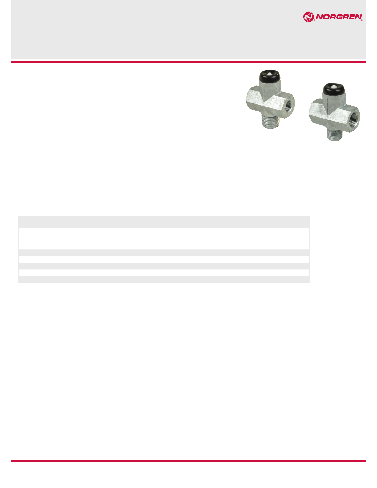
Features
Norgren GT Development 223 Series Pressure
Protection Valves are designed for convenient,
in-tank mounting, with either 3/8" or 1/2" NPT
threads. Configuration includes dual outlets, with
a variety of closing pressures to best match the
customer’s application.
Performance
Function
Limitations
Part Number
Opening and Closing Performance
Air Line Connection
Mounting
Material
The Pressure Protection Valve assembly is intended to isolate a portion of a vehicle air system if a leak
occurs, so that the integrity of the remaining system is retained. This valve to mount on an air tank.
The Pressure Protection Valve assembly is designed for use on vehicle air systems with a normal duty
cycle between 100 and up to 150 PSIG in a temperature range of –40°F to +200°F. The valve, as mounted
on the vehicle, is unprotected from the environment and is subjected to vibration conditions similar to
the vehicle.
223-XXX
Refer to Pressure Protection Valve Cross Reference document.
Threaded 3/8" NPT and 1/2" NPT inlet fittings and 1/4" NPT and 3/8" NPT female outlet.
Air tank
Zamak 3
Pressure Protection Valves
223–Series
REV: 8/14 01
Our policy is one of continued research and development. We therefore reserve the right to amend,
without notice, the specifications given in this document.
© Norgren GT Development Corporaton, 2014
Page 2
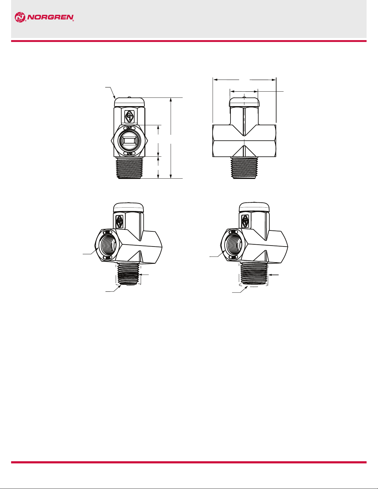
223–Series Pressure Protection Valves
Dimensions (Inches)
SPRAY CAP
1.00
REF
0.62
2.498
REF
2.00
7/8 WRENCH FLAT
OUTLET
3/8" NPT THD.
TY, 2 PL
3/8" NPT THD. COVER
INLET
Warning
Improper selection, misuse, age or malfunction of components used in
commercial vehicle systems can cause failure in various modes. The system
designer is warned to consider the failure modes of all component parts
used in commercial vehicle systems and to provide adequate safeguards to
prevent personal injury or damage to equipment or property in the event of
such failure modes. System designers and end users are cautioned to consult
instruction sheets and specifications available from the factory. The system
designer/end user is responsible for verif ying that all requirements for the
application are met.
OUTLET
3/8" NPT THD.
TY, 2 PL
1/2" NPT THD. COVER
INLET
Warranty
The products described herein are warranted subject to seller’s Standard
Terms and Condition of Sale, available at seller’s website.
02
Our policy is one of continued research and development. We therefore reserve the right to amend,
without notice, the specifications given in this document.
© Norgren GT Development Corporaton, 2014
REV: 8/14
 Loading...