

Nordyne 14 SEER, S4BE-018K, S4BE-024K, S4BE-030K, S4BE-036K Owner's Manual
...
Outdoor Air Conditioner
14 SEER R-410A High Efficiency Split System
These units have been designed and tested for
capacity and efficiency in accordance with A.R.I.
Standards. Split System Air Conditioning units
are designed for use with a wide variety of fossil
fuel furnaces, electric furnaces, air handlers, and
evaporator coil combinations.
These instructions are primarily intended to assist
qualified individuals experienced in the proper
installation of heating and/or air conditioning
appliances. Some local codes require licensed
installation/service personnel for this type of
equipment. Read all instructions carefully before
starting the installation.
USER'S INFORMATION
Read this owner information to become familiar
with the capabilities and use of your appliance.
Keep this with literature on other appliances
where you have easy access to it in the future.
If a problem occurs, check the instructions
and follow recommendations given. If these
suggestions don't eliminate your problem, call
your servicing contractor.
OPERATING INSTRUCTIONS
To Operate Your Furnace for
Heating m
1. Set the thermostat system switch to HEAT
or AUTO and the thermostat fan switch to
AUTO. (See Figure 1)
.
Set the thermostat temperature to the
desired temperature level by pressing the
WARMER or COOLER button. Please refer
to the separate detailed user's manual
for complete thermostat programming
instructions.The furnace and indoor blower
will cycle on and off to maintain the indoor
temperature at the desired heating level.
To Shut Off Your Air Conditioner
Set the thermostat system switch to OFF and the
thermostat fan switch to AUTO. (See Figure 1)
The system will not operate, regardless of the
thermostat temperature setting.
To Operate the Indoor Blower
Continuously
Set the thermostat fan switch to ON. (See
Figure 1)
To OperateYour Air Conditioner for
Cooling
1. Set the thermostat system switch to COOL
or AUTO and the thermostat fan switch to
AUTO. (See Figure 1)
.
Set the thermostat temperature to the
desired temperature level by pressing the
WARMER or COOLER button. Please refer
to the separate detailed thermostat user's
manual for complete instructions regarding
thermostat programming. The outdoor unit
and indoor blower will both cycle on and
off to maintain the indoor temperature at
the desired cooling level.
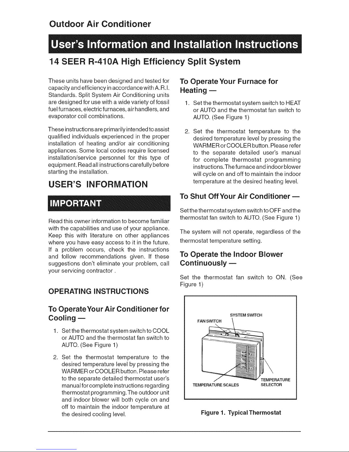
SYSTEM SWITCH
FAN SWITCH
TEMPERATURE SCALES
Figure 1. Typical Thermostat
TEMPERATURE
SELECTOR

The indoor blower will start immediately, and
will run continually until the fan switch is reset
to AUTO.
The continuous indoor blower operation can be
obtained with the thermostat system switch set
in any position, including OFR
The continuous indoor blower operation is
typically used to circulate the indoor air to
equalize a temperature unbalance due to a sun
load, cooking, or fireplace operation.
To Maintain Your Air Conditioner --
a,
The unit thermostat is properly set
-- see "To Operate Your Air Conditioner for
Cooling" and "To Operate Your Furnace for
Heating."
b. The unit disconnect fuses are in good
condition, and the electrical power to the
unit is turned on.
1. GENERAL INFORMATION
Read the following instructions completely before
performing the installation.
CAUTION:
Be certain the electrical power to
the outdoor unit and the furnace/
air handier is disconnected before
doing the following recommended
maintenance.
1. Regularly:
a,
Clean or replace the indoor air filter at the
start of each heating and cooling season,
and when an accumulation of dust and dirt
is visible on the air filter.
b. Remove any leaves and grass clippings
from the coil in the outdoor unit, being
careful not to damage the aluminum fins.
c. Check for any obstruction, such as twigs,
sticks, etc.
2. Before Each Cooling Season:
If the furnace/air handler blower motor and
the outdoor unit fan motor(s) have oil tubes
at the motor bearings, apply 10 drops of
SAE No. 20 motor oil to each oil tube.
CAUTION:
This unit uses refrigerant R=410A. DO
NOT under any circumstances use
any other refrigerant besides R=410A
in this unit. Use of another refrigerant
will damage this unit.
Condensing Unit Section -- Each condens-
ing unit is shipped with a refrigerant charge
adequate to operate the outdoor section with
an indoor matching coil or air handler, and 15
feet of refrigeration line.
NOTE: DO NOT USE ANY PORTION OF THE
CHARGE FOR PURGING OR LEAK TEST-
ING.
Matching coils and air handlers are shipped with
a small pressurized holding charge to pressurize
them to keep out contaminants. To release the
pressure, read the indoor section installation
instructions carefully.
Liquid and Suction Lines-- Refrigerant grade
copper tubing should be used when installing the
system. Refrigerant suction line tubing should
be fully insulated.
CAUTION:
Do not over=oil, or oil motors not
factory=equipped with oil tubes. The
compressor is hermetically "sealed"
and does not require lubrication.
=
Before Calling a ServiceTechnician, Be
Certain:
Field Connections for Electrical Power
Supply -- All wiring must comply with current
provisions of the "National Electrical Code" (ANSi
C1.) and with applicable local codes having
jurisdiction. The minimum size of electrical
conductors and circuit protection must be in
compliance with information listed on the outdoor
unit data label.
NOTICE:
Certain models have external panels fabricated
from a premium grade of stainlesssteeldesigned
to inhibit corrosion. For such units, if the unit is
located in acoastal region or other area subjected
to high concentrations of salt, then the unit should
be hosed off after storms and monthly otherwise
to maintain its new appearance.
2. SAFETY CONSiDERATiONS
Pressures within the System -- Split system
air conditioning equipment contains liquid and
gaseous refrigerant under pressure. Installation
and servicing of this equipment should be accom-
plished by qualified, trained personnel thoroughly
familiar with this type of equipment. Under no
circumstances should the Homeowner attempt
to install and/or service the equipment.
Labels, Tags, Precautions -- When working
with this equipment, follow all precautions in the
literature, on tags, and on labels provided with
the equipment. Read and thoroughly understand
the instructions provided with the equipment prior
to performing the installation and operational
checkout of the equipment.
Brazing Operations--Installation of equipment
may require brazing operations. Safety codes
must be complied with. Safety equipment (e.g.;
safety glasses, work gloves, fire extinguisher,
etc.) must be used when performing brazing
operations.
WARNING:
Ensure all electrical power to the unit
is off prior to installing or servicing
the equipment. Failure to do so may
cause personal injury or death.
3. SITE PREPARATION
the job site. Ensure coil fins are straight and, if
necessary, comb fins to remove flattened and
bent fins.
Preferred Location of the Outdoor Unit at the
Job Site -- Conduct a survey of the job site to
determine the optimum location for mounting
the outdoor unit. Overhead obstructions, poorly
ventilated areas, and areas subject to accumula-
tion of debris should be avoided. The outdoor
unit should be installed no closer than 18 inches
from the outside walls of the facility and in an
area free from overhead obstructions to ensure
unrestricted airflow through the outdoor unit.
Facility Prerequisites -- Electrical power
must be supplied to the equipment. Electrical
power supplied must be adequate for proper
operation of the equipment. The system must
be wired and provided with circuit protection in
accordance with local building codes and the
National Electrical Code.
4. INSTALLING THE OUTDOOR UNIT
Slab Mount--The site selected for aslab mount
installation requires astable foundation and one
not subject to erosion. The slab should be level
and anchored (if necessary) prior to placing the
equipment on the slab.
Cantilever Mount- The cantilever mount
should be designed with adequate safety factor
to support the weight of the equipment, and for
loads subjected to the mount during operation.
Installed equipment should be adequately se-
cured to the cantilever mount and levelled prior
to operation of the equipment.
Roof Mount--The method of mounting should
be designed so as not to overload roof structures
nor transmit noise to the interior of the structure.
Refrigerant and electrical line should be routed
through suitably waterproofed openings to pre-
vent water leaking into the structure.
Unpacking Equipment -- Remove the card-
board carton and User's Manual from the
equipment. Take care not to damage the tubing
connections when removing the carton.
Inspect for Damage -- Inspect the equipment
for damage prior to installing the equipment at
5. INSTALLING THE INDOOR UNIT
The indoor section should be installed before
proceeding with routing of refrigerant piping.
Consult the installation instructions of the indoor
unit (i.e.: air handler, furnace, etc.) for details
regarding installation.
6. CONNECTING REFRIGERANT
TUBING BETWEEN THE
iNDOOR AND OUTDOOR UNiT
CAUTION:
This system utilizes R-410A refrigerant
with POE oil. When servicing, cover
or seal openings to minimize the
exposure of the refrigerant system
to air to prevent accumulation of
moisture and other contaminants.
General -- Once outdoor and indoor unit place-
ment has been determined, route refrigerant
tubing between the equipment in accordance
with sound installation practices. Refrigerant
tubing should be routed in a manner that mini-
mizes the length of tubing and the number of
bends in the tubing. Refrigerant tubing should
be supported in a manner that the tubing will
not vibrate or abrade during system operation.
Tubing should be kept clean of foreign debris
during installation and installation of a liquid
line filter drier is recommended if cleanliness
or adequacy of system evacuation is unknown
or compromised. Every effort should be made
by the installer to ensure that the field installed
refrigerant containing components of the system
have been installed in accordance with these
instructions and sound installation practices
so as to insure reliable system operation and
longevity.The maximum recommended intercon-
necting refrigerant line length is 75 feet, and the
vertical elevation difference between the indoor
and outdoor sections should not exceed 20 feet.
Consult long line application guide for installa-
tions in excess of these limits.
Filter Dryer Installation--A filter dryer is
provided with the unit and must be installed in
the liquid line of the system. If the installation
replaces a system with a filter dryer already
present in the liquid line, the filter dryer must be
replaced with the one supplied. The filter dryer
must be installed in strict accordance with the
manufacturer's installation instructions.
7. MAKING ELECTRICAL
CONNECTIONS
WARNING:
Turn off all electrical power at the main
circuit box before wiring electrical
power to the outdoor unit. Failure to
comply may cause severe personnel
injury or death.
Wiring Diagram/Schematic -- A wiring dia-
gram/schematic is located on the inside cover
of the electrical box of the outdoor unit. The
installer should become familiar with the wiring
diagram/schematic before making any electrical
connections to the outdoor unit.
Outdoor Unit Connections -- The outdoor
unit requires both power and control circuit
electrical connections. Refer to the unit wiring
diagram/schematic for identification and location
of outdoor unit field wiring interfaces.
Control Circuit Wiring --The outdoor unit is
designed to operate from a 24 VAC Class IIcontrol
circuit. Control circuit wiring must comply with
the current provisions of the "National Electrical
Code" (ANSI C1.) and with applicable local codes
having jurisdiction.
Thermostat Connections -- Thermostat con-
nections should be made in accordance with the
instructions supplied with the thermostat, and
with the instructions supplied with the indoor
equipment.
Electrical PowerWiring-- Electrical power wir-
ing shall comply with the current provisions of the
"National Electrical Code" (ANSI C1 .) and with
applicable local codes having jurisdiction. Use
of rain tight conduit is recommended. Electrical
conductors shall have minimum circuit ampac-
ity in compliance with the outdoor unit rating
label. The facility shall employ electrical circuit
protection at a current rating no greater than that
indicated on the outdoor unit rating label.
Optional Equipment- Optional equipment
(e.g. :filter/driers, liquid line solenoid valves, etc.)
should be installed in strict accordance with the
manufacturer's installation instructions.
Minimum Circuit Ampacity-- Electrical wiring
to the equipment must be compatible and in
compliance with the minimum circuit ampacity
listed on the outdoor unit data label.
 Loading...