

Nordyne S3BM-120G Owner's Manual
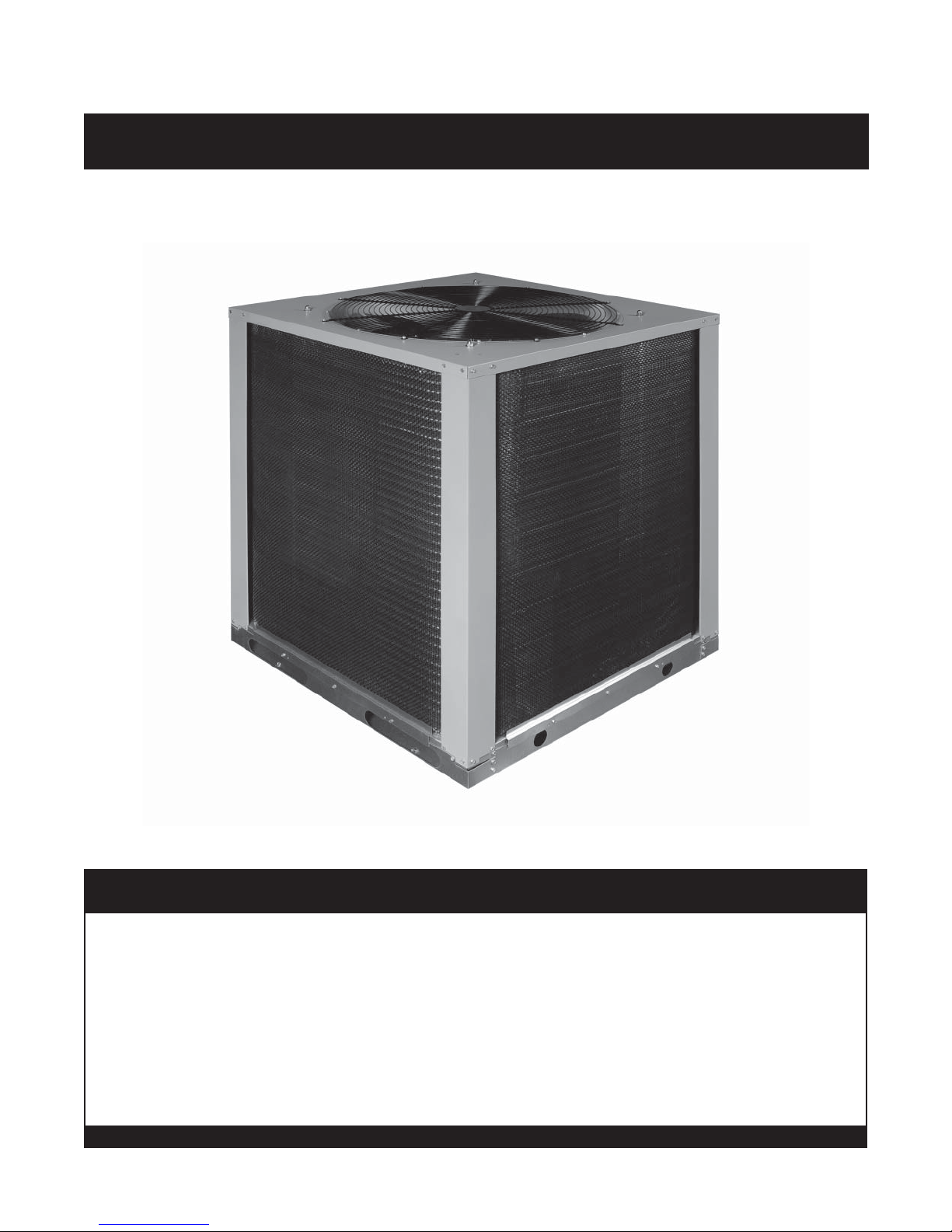
Outdoor Air Conditioner
USER’S INFORMATION AND INSTALLATION INSTRUCTIONS
S3BM-120G High Effi ciency Commercial Split System
Read this owner information thoroughly and become familiar with the capabilities and use of your appliance before
attempting to operate or maintain this unit. Keep this literature where you have easy access to it in the future. If
a problem occurs, check the instructions and follow recommendations given. If these suggestions don’t eliminate
your problem, call your NORDYNE Servicing Contractor (Service PRO).
Any additions, changes, or conversions required for the appliance to satisfactorily meet the application needs must
be made by a qualifi ed installer, service agency, or the gas supplier using factory specifi ed and approved parts.
These instructions are primarily intended to assist qualifi ed individuals experienced in the proper installation of
this appliance. Some local codes require licensed installation/service personnel for this type of equipment. Please
read all instructions carefully before starting the installation.
DO NOT DESTROY. PLEASE READ CAREFULLY AND KEEP IN A SAFE PLACE FOR FUTURE REFERENCE.
IMPORTANT

TABLE OF CONTENTS
USER’S INFORMATION
SAFETY INFORMATION .............................................3
OPERATING INSTRUCTIONS ..................................... 3
Cooling Operation ....................................................3
Heating Operation ...................................................3
Operating the Indoor Blower Continuously .............. 3
System Shutdown ....................................................3
SYSTEM MAINTENANCE ...........................................3
Regular Cleaning ..................................................... 3
Motor Lubrication ..................................................... 3
TROUBLESHOOTING .................................................3
INSTALLER’S INFORMATION
SAFETY INFORMATION .............................................4
Pressures Within The System ................................. 4
Labels, Tags and Precautions .................................. 4
Brazing Operations .................................................. 4
GENERAL INFORMATION ..........................................4
Condensing Unit ......................................................4
Liquid and Suction Lines .........................................4
Field Connections for Electrical Supply ...................4
SITE PREPARATION ...................................................4
Unpacking the Equipment .......................................4
Inspect For Damage ................................................4
Preferred Location Of The Outdoor Unit ..................4
Facility Prerequisites................................................4
Minimum Circuit Ampacity .......................................5
Maximum Fuse/Circuit Breaker Size ....................... 5
INSTALLING THE OUTDOOR UNIT ............................5
Slab Mount ..............................................................5
Cantilever Mount......................................................5
Roof Mount ..............................................................5
INSTALLING THE INDOOR UNIT ................................5
CONNECTING REFRIGERANT TUBING ....................5
General .................................................................... 5
Optional Equipment .................................................5
ELECTRICAL REQUIREMENTS ................................. 6
Pre-Electrical Checklist .................................................6
Wiring Diagram/Schematic ...........................................6
Supply Control Circuit Wiring ........................................6
Line Voltage ..................................................................6
Outdoor Unit Connections ............................................ 6
Disconnect Switch ........................................................ 6
Optional Equipment ......................................................6
Thermostat Connections ..............................................6
Grounding ..................................................................... 7
STARTUP AND CHECKOUT .......................................7
Air Filters ......................................................................7
Thermostat ...................................................................7
Outdoor Unit ................................................................. 7
System Cooling ............................................................7
Short Cycle Protection .................................................. 7
Heating .........................................................................7
Indoor Blower ...............................................................7
Adjustment Of Refrigerant Charge ............................... 8
Refrigerant Charging Chart ..........................................8
Optional Equipment ......................................................8
2
ACCESSORIES ...........................................................8
Condensing Unit ......................................................8
USER’S INFORMATION
SAFETY INFORMATION
Safety markings are used frequently throughout this
manual to designate a degree or level of seriousness and
should not be ignored. WARNING indicates a potentially
hazardous situation that if not avoided, could result in
personal injury or death. CAUTION indicates a potentially
hazardous situation that if not avoided, may result in minor
or moderate injury or property damage.
OPERATING INSTRUCTIONS
Cooling Operation
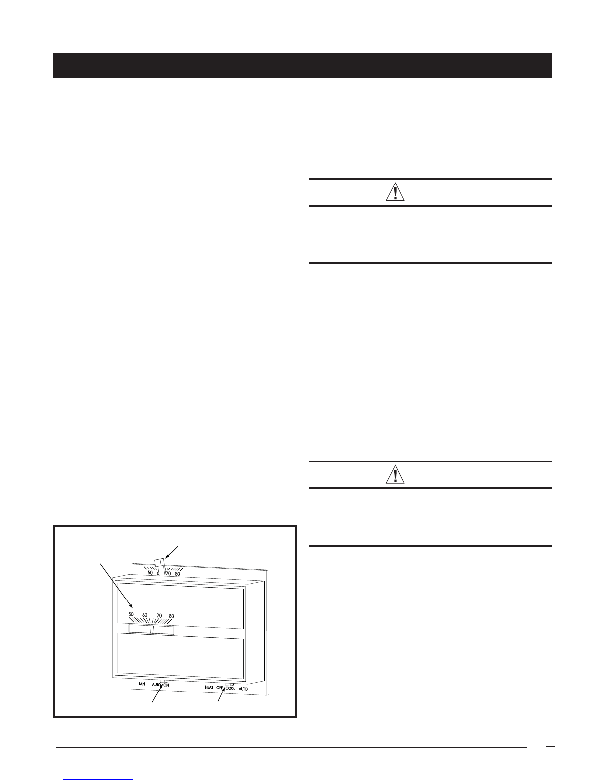
1. Set the thermostat system switch (Figure 1) to COOL
or AUTO and the thermostat fan switch to AUTO.
2. Set the thermostat temperature selector to the desired
temperature level. The outdoor fan(s), compressor(s),
and blower motor(s) will all cycle on and off to maintain
the indoor temperature at the desired cooling level.
Heating Operation
1. Set the thermostat system switch (Figure 1) to HEAT
or AUTO and the thermostat fan switch to AUTO.
2. Set the thermostat temperature selector to the desired
temperature level. The furnace/air handler blower
motor(s) will cycle on and off to maintain the indoor
temperature at the desired heating level.
Fan Mode
Fan Mode is typically used to circulate the indoor air to
equalize a temperature imbalance due to a solar load,
cooking, or fi replace operation. The continuous indoor
blower operation can be obtained with the system switch
set in any position, including OFF.
Set the thermostat’s fan switch to ON.
will start immediately, and run continuously until the fan
switch is reset to AUTO.
Temperature
Selector
Thermometer
The indoor blower
System Shutdown
Set the thermostat system switch (See Figure 1) to OFF
and the thermostat fan switch to AUTO. NOTE: The
system will not operate, regardless of the temperature
selector setting.
SYSTEM MAINTENANCE
CAUTION:
Shut off all electrical power to the unit before
performing any maintenance or service on the
system. Failure to comply may result in personal
injury or death.
Proper maintenance is most important to achieve the best
performance from the appliance and should be performed
by a qualifi ed service technician at least once a year.
Follow the maintenance schedule and the instructions
below for years of safe, trouble free operation.
Regular Cleaning
• Clean or replace the indoor air fi lter at the start of each
heating and cooling season, and when an accumulation
of dust and dirt is visible on the air fi lter.
• Remove any leaves and grass clippings from the coil
in the outdoor unit, being careful not to damage the
aluminum fi ns.
• Check for obstructions, such as twigs, sticks, etc.
Motor Lubrication
CAUTION:
Do not over-fi ll or oil a motor that is not factory
equipped with oil tubes. The compressor in
this unit is factory sealed and does not require
lubrication.
If the furnace/air handler blower motor(s) and the outdoor
unit fan motor(s) have oil tubes at the motor bearings,
apply 10 drops of SAE No. 20 motor oil to each oil tube
before each cooling season.
Fan Switch
Figure 1. Typical Thermostat
System Switch
TROUBLESHOOTING
If the unit fails to operate, check the following:
• The thermostat is properly set. See Cooling Operation
for air conditioning or Heating Operation for furnace or
air handler.
• The unit disconnect fuses are in good condition and
the electrical power to the unit is turned on.
3
INSTALLER’S INFORMATION
SAFETY INFORMATION
Safety markings are used frequently throughout this
manual to designate a degree or level of seriousness and
should not be ignored. WARNING indicates a potentially
hazardous situation that if not avoided, could result in
personal injury or death. CAUTION indicates a potentially
hazardous situation that if not avoided, may result in minor
or moderate injury or property damage.
WARNING:
Shut off all electrical power to the unit before
performing any maintenance or service on the
system. Failure to comply may result in personal
injury or death.
Pressures within the System
Split system air conditioning equipment contain liquid
and gaseous refrigerant under pressure. Installation
and servicing of this equipment should be performed
by qualifi ed, trained personnel thoroughly familiar with
this type of equipment. Under no circumstances should
non-qualifi ed personnel attempt to install and/or service
the equipment.
Labels, Tags, Precautions
When working with this equipment, follow all precautions
in the literature, on tags, and labels provided with
the equipment. Read and thoroughly understand
the instructions provided with the equipment prior to
performing the installation and operational checkout of
the equipment.
Brazing Operations
Installation of equipment may require brazing operations.
Safety codes must be complied with. Safety equipment
(e.g.; safety glasses, work gloves, fi re extinguisher, etc.)
must be used when performing brazing operations.
Please consult your dealer for maintenance information
and availability of maintenance contracts. Please read all
instructions before installing the unit.
Condensing Unit
Each condensing unit is shipped with a refrigerant holding
charge adequate to maintain a positive pressure to keep
out contaminants. NOTE: Do not use any portion of the
charge for purging or leak testing.
Liquid and Suction Lines
Refrigerant grade copper tubing should be used when
installing the system. Refrigerant suction line tubing should
be fully insulated.
When condensing unit is matched with two air handlers
(two coils) or a dual circuit evaporator coil, refrigerant
tubing should be branched between both evaporator coils
or circuits using equal lengths of tubing to maintain equal
evaporator/circuit performance.
Field Connections for Electrical Power Supply
All wiring must comply with applicable local codes having
jurisdiction. The minimum size of electrical conductors and
circuit protection must be in compliance with information
listed on the outdoor unit data label.
SITE PREPARATION
Unpacking Equipment
Remove the cardboard carton and User’s Manual from the
equipment. Take care not to damage the tubing connections
when removing the carton.
Inspect for Damage
Inspect the equipment for damage prior to installing the
equipment at the job site. Ensure coil fi ns are straight
and, if necessary, comb fi ns to remove fl attened and
bent fi ns.
GENERAL INFORMATION
This unit has been designed and tested for capacity and
effi ciency in accordance with A.R.I. 340/360 Standards.
This unit will provide many years of safe and dependable
comfort, providing it is properly installed and maintained.
With regular maintenance, this unit will operate satisfactorily
year after year. Abuse, improper use, and/or improper
maintenance can shorten the life of the appliance and
create unsafe hazards.
To achieve optimum performance and minimize equipment
failure, it is recommended that periodic maintenance be
performed on this unit. The ability to properly perform
maintenance on this equipment requires certain
mechanical skills and tools.
4
Preferred Location of the Outdoor Unit
Conduct a survey of the job site to determine the
optimum location for mounting the outdoor unit. Overhead
obstructions, poorly ventilated areas, and areas subject
to accumulation of debris should be avoided. The outdoor
unit should be installed no closer than 18 inches from
the outside walls of the facility and in an area free from
overhead obstructions to ensure unrestricted airfl ow
through the outdoor unit.
Facility Prerequisites
Electrical power supplied to the unit must be adequate for
proper operation of the equipment. The system must be
wired and provided with circuit protection in accordance
with local building codes.
 Loading...