

Nordyne R4GD 024K045, R4GD 030K072, R4GD 024K072, R4GD 030K045, R4GD 036K072 Installation Instructions Manual
...Page 1
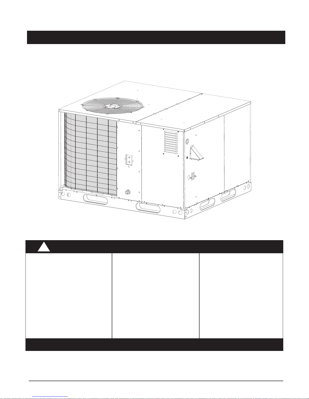
High Efficiency
Installation Instructions
Single Package Gas Heating/Electric Cooling
WARNING:
!
Improper installation, adjustment, alteration, service, or maintenance can
cause injury or property
damage. Refer to this manual. For assistance or additional information consult a
qualified installer, service
agency, or the gas supplier.
DO NOT DESTROY. PLEASE READ CAREFULLY AND KEEP IN A SAFE PLACE FOR FUTURE REFERENCE.
These instructions are primarily intended to assist qualified individuals experienced in the proper installation of this
appliance. Some local codes require licensed installation/service personnel for this type of equipment. Read all
instructions carefully before starting the installation.
FOR YOUR SAFETY
Do not store or use gasoline
or other flammable vapors
and liquids in the vicinity of
this or any other appliance.
WHAT TO DO IF YOU SMELL GAS
• Do not try to light any
• Do not touch any electrical
• Immediately call your gas
• If you cannot reach your gas
• Extinguish any open flame.
FOR YOUR SAFETY
appliance.
switch; do not use any phone
in your building.
supplier from a neighbor's
phone. Follow the gas
supplier's instructions.
supplier, call the fire
department.
Page 2

2
Page 3

TABLE OF CONTENTS
GENERAL SPECIFICATIONS ..................................... 4
SAFETY CONSIDERATIONS...................................... 4
• Literature, Labels, and Tags..................................4
• Pressures Within The System .............................. 4
INSTALLATION REQUIREMENTS .............................. 4
• Equipment Application .......................................... 4
• Equipment Check ................................................. 4
• Requirements and Codes...................................... 4
• Unit Location......................................................... 4
• Venting Requirements........................................... 4
• Unit Dimensions ................................................ 5-6
• Clearances to Combustible Materials.................... 7
• Thermostat ........................................................... 7
• Air Filter Requirements ......................................... 7
• Condensate Drain ................................................. 9
UNIT INSTALLATION .................................................. 9
• Ground Level ........................................................ 9
• Rigging and Hoisting ............................................. 9
• Rooftop ................................................................. 9
AIR SUPPLY FOR COMBUSTION
AND VENTILATION .............................................. 10
CIRCULATING AIR SUPPLY ..................................... 10
• Airflow Data ........................................................ 11
• Unconditioned Spaces ........................................ 12
• Acoustical Ductwork ........................................... 12
• Horizontal to Down Flow Conversion ................... 12
GAS SUPPLY AND PIPING ...................................... 12
• Leak Check ........................................................ 13
GAS AND HIGH ALTITUDE CONVERSIONS ............ 13
• High Altitude Application ..................................... 13
• Natural Gas High Altitude Conversion ................. 13
• LP/Propane Gas Conversion............................... 13
ELECTRICAL WIRING............................................... 14
• General ............................................................... 14
• Line Voltage........................................................ 14
• Electrical Data Table .......................................... 15
• Blower Speed ..................................................... 15
• Room Thermostat ............................................... 16
SYSTEM CHECK ..................................................... 16
• Pre-Start Check List .......................................... 16
WIRING DIAGRAMS ................................................ 18
START-UP PROCEDURE......................................... 16
• Air Circulation .................................................... 16
• Short Cycle Protection ....................................... 19
• System Cooling ................................................. 19
• System Heating ................................................. 19
• Verifying and Adjusting Firing Rate .................... 19
• Verifying and Adjusting Temperature Rise ......... 19
• Lighting/Operating Instructions .......................... 20
• Verifying Burner Operation ................................. 21
• Verifying Operation of Over-Temperature
Limit Control ................................................... 21
COMPONENT FUNCTIONS ..................................... 21
• Flame Sensor .................................................... 21
• Flame Roll-Out Control....................................... 21
• Gas Valve.......................................................... 21
• Pressure Switch ................................................ 21
• Over-Temperature Limit Control ......................... 21
UNIT MAINTENANCE............................................... 21
• Refrigerant Charging .......................................... 22
• Routine Maintenance ......................................... 22
• Air Filter............................................................. 22
• Vent Cover Assembly ........................................ 22
• Condensate Drain and Outdoor Coil ................... 22
• Electrical ........................................................... 23
• Motor Lubrication ............................................... 23
• Blower Compartment ......................................... 23
• Heat Exchanger and Burner Maintenance .......... 23
• Cleaning of Heat Exchanger............................... 23
• Cleaning of Burners ........................................... 24
OPERATING SEQUENCE ........................................ 24
• Cooling Mode..................................................... 24
• Blower Mode ...................................................... 24
• Heating Mode .................................................... 24
• Unit Fails to Operate.......................................... 2 5
INSTALLATION CHECKLIST................................... 26
3
Page 4
GENERAL SPECIFICATIONS
!
!
Single Package Gas Heating/Electric Cooling units are
designed for outdoor rooftop or ground level slab installations.
The units are shipped ready for horizontal duct connections
and are easily converted for down flow connections.
All models are shipped from the factory with the following:
1. Multispeed fixed torque variable speed blower.
2. Horizontal or down flow duct connections.
3. 24V fuse protection.
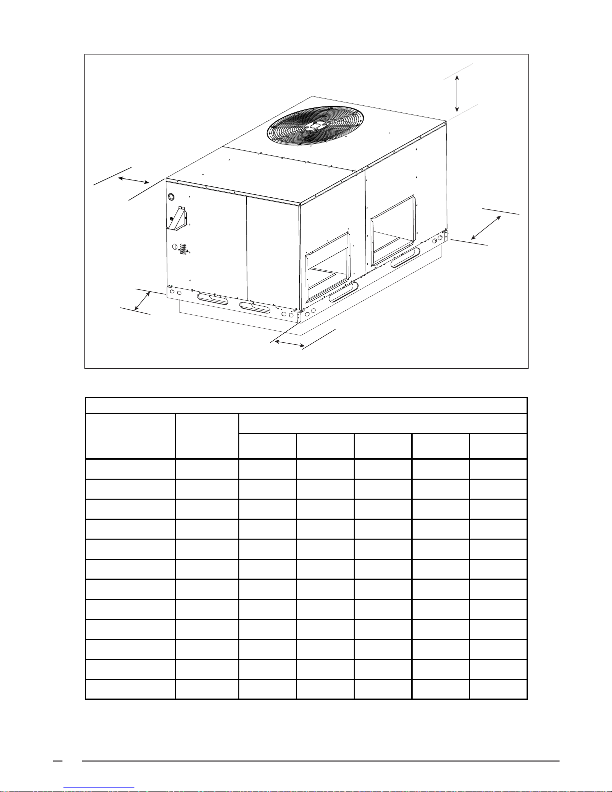
The unit dimensions are shown in Figure 1.
SAFETY CONSIDERATIONS
It is the responsibility of the installer to ensure that the
installation is made in accordance with all applicable local
and national codes.
WARNING:
Improper installation, service, adjustment, or
maintenance may cause explosion, fire, electrical
shock or other hazardous conditions which may
result in personal injury or property damage.
Unless otherwise noted in these instructions,
only factory authorized kits or accessories may
be used with this product.
Equipment Check — All units have been securely packaged
at the point of shipment. After unpacking the unit, carefully
inspect it for apparent and concealed damage. Claims for
damage should be filed with the carrier by the consignee.
Requirements and Codes — The installer must comply
with all local codes and regulations which govern this type
equipment. Local codes and regulations take precedence
over any recommendations contained in these instructions.
In the absence of local codes, the installation must
conform with the National Fuel Gas Code (ANSI 2223.1,
NFPA-54), or Canadian installations must conform with
CAN/CGA-B149 installation codes. All electrical wiring
must be made in accordance with codes and regulations
and with the National Electric Code (ANSI/NFPA 70) or in
Canada the Canadian Electric Code Part 1 CSA C.22.1. Air
Ducts must be installed in accordance with the standards
of the National Fire Protection Association “Standards for
Installation of Air Conditioning and Ventilation Systems”
(NFPA 90A), “Standard for Installation of Residence Type
Warm Air Heating and Air Conditioning Systems” (NFPA
90B), these instructions, and all applicable local codes.
The National Fuel Gas Code is available by writing:
American National Standards Institute, Inc.
1430 Broadway
New York, NY 10018
NFPA publications are available by writing:
National Fire Protection Association
Batterymarch Park
Quincy, ME 02269
Literature, Labels, and Tags — When working with this
equipment, follow all precautions in the literature, on tags,
and on labels provided with the unit and/or approved field
installed kits. The type of hazard and severity are described
on each label or tag.
Pressures Within The System — This equipment contains
liquid and gaseous refrigerant under high pressure.
Installation or servicing should only be performed by
qualified trained personnel thoroughly familiar with this type
equipment.
INSTALLATION REQUIREMENTS
Equipment Application — Before beginning the installation,
verify that the unit model is correct for the job. The unit
model number is printed on the data label. This furnace is
NOT to be used for temporary heating of buildings or
structures under construction.
4
Unit Location — The gas/electric unit is designed only for
outdoor installations. Choosing the location of the unit
should be based on minimizing the length of the supply and
return ducts. Consideration should also be given to
availability of fuel, electric power, service access, noise,
and shade.
Venting Requirements — This unit has been equipped
with an integral venting system and designed to operate
only with this venting system. No additional venting shall
be used. This unit must be vented to the outdoors.
WARNING:
Do not vent furnace through a conventional
venting system.
Page 5
3
.0
.0
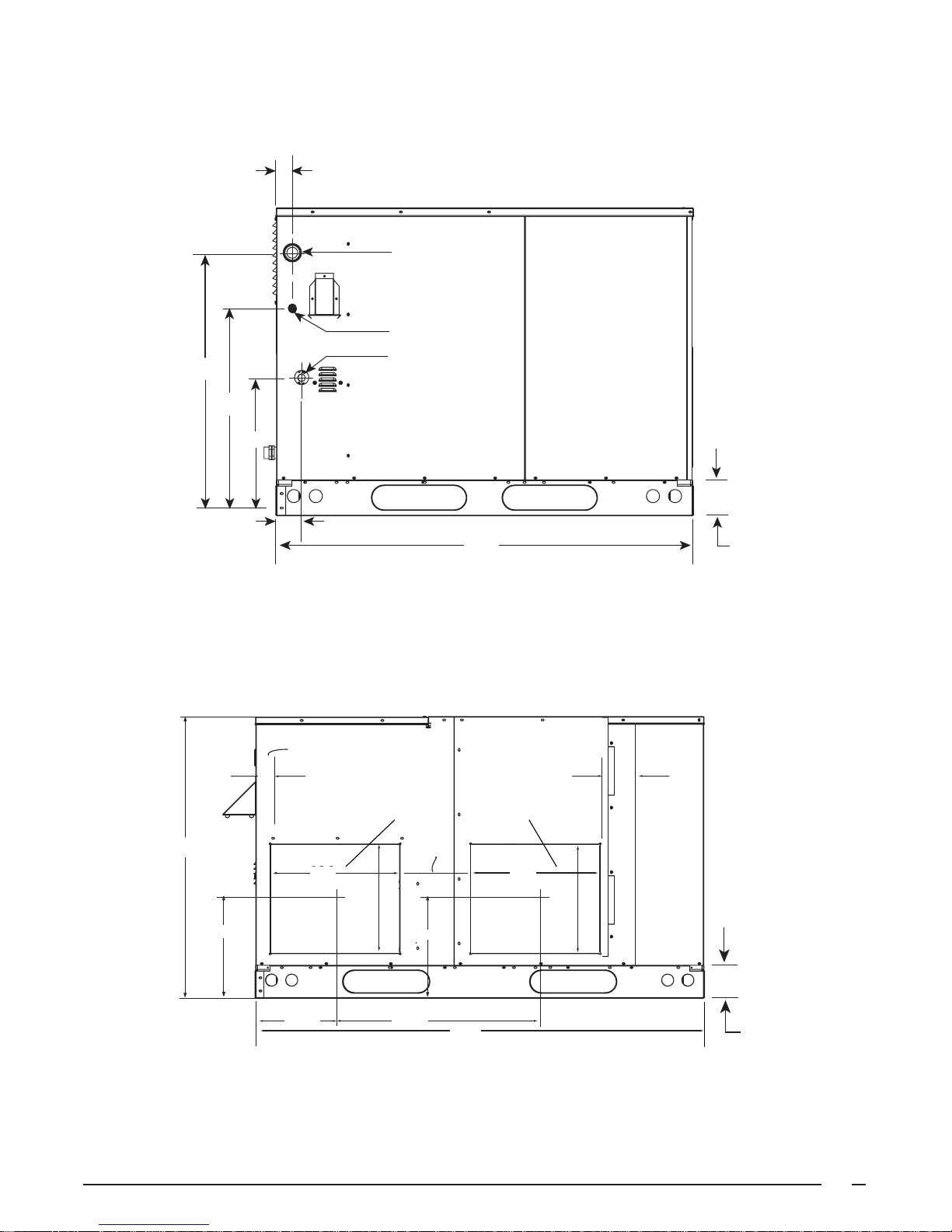
DIMENSIONS
1.0
24.6
1.8
16.6
2.9
Electric
Supply Entry
Low V oltage Entry
Gas Supply
Entry
47.5
4
Side View
1.75
Horizontal
Supply Duct
Opening
C
16.0
16.0
8.75
13.5
12.45
9.75 24.75
12.45
Horizontal
Return Duct
Opening
16.0
13.5
55.8
4.0
Condensing
Coil
4
Back View
5
Page 6

4
5
DIMENSIONS-Continued
Center of Gravity
Height (in inches)
C
R4GD
Shipping
To Electrical
Opening
5.7
B
13.3
Downflow
Supply Duct
Opening
12.0
13.5
24.9
A
16.0
23.5
CG
13.5
16.0
Downflow
Return Duct
Opening
Inside
Perimeter
of Base Rail
2.63"
12.0
47.
Top View
Model
Number
Unit
Weight
Weight A B
with base rails without base rails
024K045† 425 435 26.5 26.5 39.0 35.3
024K072† 435 445 26.0 26.5 39.0 35.3
030K045† 430 440 26.5 26.5 39.0 35.3
030K072† 440 450 26.0 26.5 39.0 35.3
036K072† 470 480 26.5 26.5 39.0 35.3
036K096† 485 495 26.0 26.5 39.0 35.3
042K072† 500 510 27.0 26.5 39.0 35.3
042K096† 515 525 27.0 26.5 39.0 35.3
048K096† 540 550 27.5 26.5 43.0 39.3
048K120† 555 565 27.5 26.5 43.0 39.3
060K096† 560 570 27.5 26.5 43.0 39.3
060K120† 575 585 27.5 26.5 43.0 39.3
† Denotes either "C" or "X"
6
Page 7
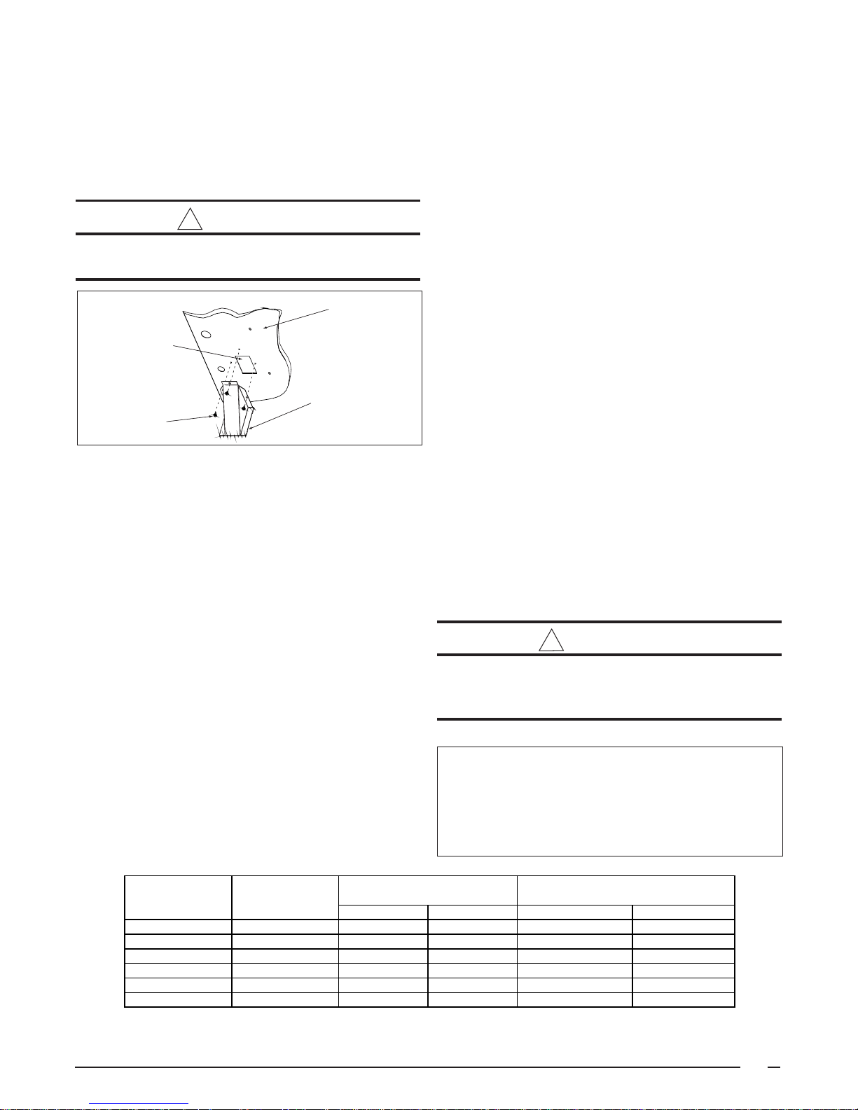
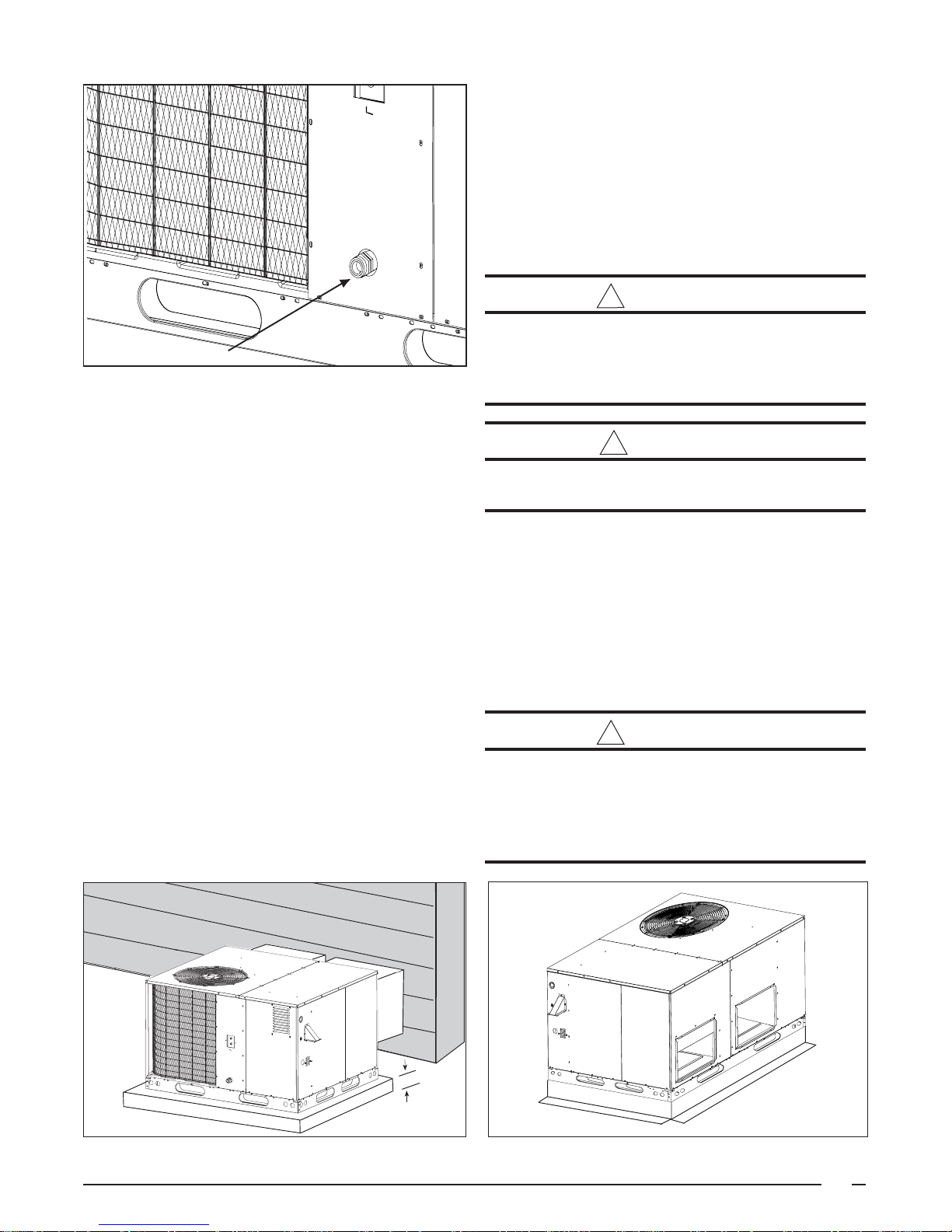
A vent cover assembly has been supplied with the unit. It
!
!
can be found secured to the gas controls within the control
area of this unit. Figure 2 shows the proper installation of
the vent cover assembly over the vent outlet on the exterior
of the corner panel. The fasteners used to secure the vent
cover assembly have been included in the homeowner's
package.
WARNING:
The vent cover assembly must be installed to
assure proper operation of the unit.
Corner Panel
of Unit
Exhaust Duct
Opening
Vent Cover
Assembly
Fastener
Figure 2. Vent Assembly
The following list is a summary of the requirements for the
location of the termination of the venting system:
1. The location of the vent termination must be consistent
with the National Fuel Gas Code (ANSI Z223.1) or CAN/
CGA-B149 Installation Codes.
2. The vent termination must be located at least four (4)
feet horizontally from any electric meters, gas meters,
regulators, and relief equipment.
3. The vent termination must be located at least three (3) feet
above any forced air inlet located within ten (10) feet.
4. The vent termination must be located at least four (4) feet
below, four (4) feet horizontally from, or one (1) foot above any
door, window, or gravity air inlet into any building.
5. The vent termination must be located at least one (1)
foot above grade.
6. The unit should be installed in such a manner as to
prevent snow accumulation from obstructing the vent
termination.
7. The unit installation shall avoid areas where condensate
drainage may cause problems by dropping on planters
or patios, etc. Furthermore, ensure that the exhaust
gases will not impinge on windows or building surfaces,
which may be compromised or damaged by
condensation. Do not install the unit such that exhaust
from the vent termination is directed into window wells,
stairwells, under decks, or in alcoves or similarly
recessed areas. The vent termination must not be
located above any public walkways.
Clearances to Combustible Materials — See Table 2 for
required clearances to combustible materials. Refer to the
unit data label for the model number. The gas/electric unit
is suitable for installation on combustible flooring or class
A, B, or C roofing materials. A clearance of at least 36
inches from the blower access panel and from the louvered
control access panel is recommended to allow for servicing
and maintenance. Where accessibility to combustibles
clearances are greater than minimum clearances,
accessibility clearances must take preference. Sufficient
clearance for unobstructed airflow through the louvered
control access panel and through the outdoor coil must be
maintained in order to achieve rated performance. See
Figure 3 for minimum clearances to obstructions.
Thermostat — A single stage cooling/single stage heating
24VAC thermostat should be used with these units. A twostage cooling/single-stage heating thermostat is
recommended for economizer operation.
Air Filter Requirements — A suitable air filter system
must be installed in the unit or in the return air system
upstream of the evaporator coil. Refer to Table 1 for
recommended filter sizes. Air filter pressure drop must not
exceed 0.08 inches WC. This unit is not supplied with air
WARNING:
Never operate unit without a filter. A failure to
follow this warning could result in a fire, personal
injury, or death.
IMPORTANT NOTICE TO INSTALLER: After installing
or replacing the filtration system for this unit, add the
following marking on the filter service panel or reasonably
adjacent thereto: “Replace filter(s) installed in your
system only with the same dimensional size filters
that are being replaced.”
Nominal Approximate Approximate Recommended
Cooling Air Flow Range Filter Area (Sq. In.)* Filter Size (In. x In.)
Tonnage (Ton) (CFM) Disposable High Velocity Disposable High Velocity
2.0 600-1200 450 275 20 x 25 15 x 20
2.5 600-1200 550 325 20 x 30 16 x 20
3.0 800-1250 625 375 25 x 25 20 x 20
3.5 850-1500 725 450 24 x 30 20 x 25
4.0 1050-1650 825 500 18 x 24 (2 required) 20 x 25
5.0 1050-1650 1000 600 20 x 25 (2 required) 25 x 25
*Based on velocity of 300 ft/min for disposable filters and 500 ft/min for high velocity (cleanable) filters.
Table 1. Air Filter Requirements
7
Page 8
A
C
Blower
Control
Duct
Coil
Minimum Clearances to Combustible Material**
E
B
D
Figure 3. Minimum Clearances.
Heating
Model
Number
024(-)045(†) 45 ,000 36 36 1* 36 36
024(-)072(†) 72 ,000 36 36 1* 36 36
030(-)045(†) 45 ,000 36 36 1* 36 36
030(-)072(†) 72 ,000 36 36 1* 36 36
036(-)072(†) 72 ,000 36 36 1* 36 36
036(-)096(†) 96 ,000 36 36 1* 36 36
042(-)072(†) 72 ,000 36 36 1* 36 36
042(-)096(†) 96 ,000 36 36 1* 36 36
048(-)096(†) 96 ,000 36 36 1* 36 36
048(-)120(†) 120,000 36 36 1* 36 36
060(-)96(†) 96,000 36 36 1* 36 36
060(-)120(†) 120,000 36 36 1* 36 36
* If accessories (filters, economizers, fresh air dampers . . .) are installed, see accessory installation instructions for proper clearances.
**Suitable for installation on combustible flooring or class A, B, or C roofing material.
† Can be C or X.
Input
(Btuh)
Panel (A) Panel (B) Panel (C) End (D) T o p (E)
Minimum Clearances (Inches)
Table 2. Minimum Clearances to Combustible Materials.
8
Page 9
!
!
!
Condensate Drain
Figure 4. Condensate Drain.
filter(s) and has no factory equipped means for
accommodating internal air filter(s). For downflow
installations only, an internal filter accessory kit can be
ordered. For horizontal installations, the air filter system
must be installed in the return air ductwork. All return air
to this unit must pass through the filter(s) before entering
the evaporator coil.
Rigging and Hoisting — The unit should be lifted using
slings and spreader bars. The spreader bars are necessary
to prevent damaging the top of the unit’s cabinet. Make
sure
that the lifting equipment is adequate for the load.
Refer to Figure 1 for unit weights. Keep the unit in an
upright position at all times. The rigging must be located
outside the unit’s center of gravity. Refer to Figure 1 for
center of gravity location. For rooftop installations,
remove and discard the two supports attached beneath
the unit.
WARNING:
To avoid the risk of property damage or personal
injury, it is the rigger’s responsibility to ensure
that whatever means are used to hoist the unit
are safe and adequate.
CAUTION:
All panels must be securely in place when rigging
and hoisting.
Condensate Drain — Condensate is removed from the
unit through the 3/4" female pipe fitting located on the front
side of the unit. (See Figure 4.) Install a 2 inch deep
condensate trap in the drain line of the same size and prime
with water.
When connecting rigid drain line, hold the female fitting with
a wrench to prevent twisting. Do not over tighten! Refer
to local codes and restrictions for proper condensate
disposal requirements.
UNIT INSTALLATION
Ground Level — When installing the unit at ground level
(See Figure 5), provide a concrete mounting pad separate
from the building foundation. The pad must be level to insure
proper condensate disposal and strong enough to support the
unit’s weight (Refer to Figure 1). Make sure the slab is a
minimum of 2" above the grade and in an area that drains well.
Rooftop — For rooftop installations (See Figure 6) use the
appropriate accessory roof curb and follow all instructions
included with it. Make sure the supports beneath the unit
have been removed. Locate the unit according to local
building codes and ordinances. The curb must be level to
insure proper condensate drainage.
The roof must be capable of handling the weight of the unit.
See Figure 1 for unit weights. Reinforce the roof if
required.
WARNING:
Do not place combustible material on or against
the unit cabinet. Do not place combustible
materials, including gasoline and any other
flammable vapors and liquids, in the vicinity of
the unit.
Figure 5. Ground Level Installation.
2"
2”
Figure 6. Roof Curb Installation.
9
Page 10

AIR SUPPLY FOR COMBUSTION AND
!
!
!
VENTILATION
CIRCULATING AIR SUPPLY
Provisions must be made in the installation of this unit to
provide an adequate supply of air for combustion. Detailed
instructions for determining the adequacy of an installation
can be found in the current revision of the National Fuel Gas
Code (ANSI Z223.1) and NFPA 54, or in Canadian installation
codes (CAN/CGA-B149), or in applicable local building
codes. Consult local codes for special requirements.
WARNING:
Installation using methods other than those
described in the following sections must comply
with the National Fuel Gas Code and all applicable
local codes to provide sufficient combustion air
for the furnace.
If the unit is operated with inadequate combustion air
supply the flame roll-out control located above the burners
will open, turning off the gas supply to the burners. The
flame roll-out control is a manually re-setable device. DO
NOT install a jumper wire across this control to defeat its
function. DO NOT reset the control without identifying and
correcting the fault condition which caused the control to
trip. If this control must be replaced, use only the replacement
part specified in the Replacement Parts List.
Air Openings in the door of the unit, warm air registers, and
return air grilles must not be restricted.
To maximize heat exchanger life, the combustion air
must be free of chemical contaminants which form
corrosive acidic compounds when combusted. Some
examples of these chemical contaminants are chlorine,
fluorine, and sulphur. Some common sources of these
chemical contaminants are detergents, bleaches,
aerosol sprays, cleaning solvents, and a wide variety of
commercial and household products.
WARNING:
Combustible air must not be drawn from a
contaminated atmosphere. Excessive exposure
to contaminated combustion air will result in
safety and performance related problems.
WARNING:
Products of combustion must not be allowed to
enter the return air ductwork or the circulating
air supply. Failure to prevent products of
combustion from being circulated into the living
space can create potentially hazardous conditions
including carbon monoxide poisoning that could
result in personal injury or death.
All return ductwork must be adequately sealed,
all joints must be taped, and the ductwork must
be secured to the unit with sheet metal screws.
When return air is provided through the bottom
of the unit, the joint between the unit and the
return air plenum must be air tight.
The roof curb or cement pad on which the unit is
mounted must provide sound physical support
of the unit with no gaps, cracks, or sagging
between the unit and the curb or pad.
Return air and circulating air ductwork must not
be connected to any other heat producing device
such as a fireplace insert, stove, etc. Doing so
may result in fire, explosion, carbon monoxide
poisoning, personal injury, or property damage.
This unit is designed only for use with a supply and return
duct. Air ducts should be installed in accordance with all
applicable local codes and the standards of the National
Fire Protection Association “Standard for Installation of Air
Conditioning Systems” (NFPA 90A), and “Standard for
Installation of Residence Type Warm Air Heating and Air
Conditioning Systems” (NFPA 90B).
Design the ductwork according to methods described by
the Air Conditioning Contractors of America (ACCA) Manual
D. The ducts must be properly sized not to exceed 0.2
inches WC pressure drop at 400 scfm per nominal ton of
cooling capacity.
Ductwork should be attached directly to the unit flanges for
horizontal applications. On roof curb installations the ducts
must be attached to the curb duct supports, not the unit.
10
Page 11

T1
845
735
625
60
72
--
217
207
* T2
905
830
750
47
51
56
515
495
** T3
950
880
810
43
46
49
600
570
T4
1110
1065
1020
34
36
37
825
790
T5
1260
1215
1175
--
30
31
990
960
T1
845
735
625
--
--
--
217
207
* T2
905
830
750
--
--
--
515
495
** T3
950
880
810
69
--
--
600
570
T4
1110
1065
1,020
54
57
60
825
790
T5
1260
1215
1,175
46
48
50
990
960
T1
845
735
625
60
72
--
217
207
T2
905
830
750
47
51
56
515
495
** T3
950
880
810
43
46
49
600
570
* T4
1110
1065
1,020
34
36
37
825
790
T5
1260
1215
1,175
--
30
31
990
960
T1
845
735
625
--
--
--
217
207
T2
905
830
750
--
--
--
515
495
** T3
950
880
810
69
--
--
600
570
* T4
1110
1065
1,020
54
57
60
825
790
T5
1260
1215
1,175
46
48
50
990
960
T1
950
880
810
69
--
--
600
570
T2
1110
1065
1020
54
57
60
825
790
T3
1220
1180
1135
48
50
52
945
915
** T4
1260
1215
1175
46
48
50
990
960
* T5
1345
1300
1250
43
44
46
1070
1030
T1
950
880
810
--
--
--
600
570
T2
1110
1065
1020
72
--
--
825
790
T3
1220
1180
1135
64
67
70
945
915
** T4
1260
1215
1175
62
65
67
990
960
* T5
1345
1300
1250
57
59
62
1070
1030
T1
1020
940
860
65
70
--
615
570
T2
1185
1110
1035
53
56
59
820
785
* T3
1410
1330
1250
43
45
48
1030
975
** T4
1525
1450
1370
--
41
43
1150
1100
T5
1650
1585
1520
--
--
--
1280
1235
T1
1020
940
860
--
--
--
615
570
T2
1185
1110
1035
--
--
--
820
785
* T3
1410
1330
1250
58
61
64
1030
975
** T4
1525
1450
1370
53
55
57
1150
1100
T5
1650
1585
1520
47
49
52
1280
1235
T1
1185
1110
1035
71
75
--
820
785
T2
1410
1330
1250
58
61
64
1030
975
T3
1525
1450
1370
53
55
57
1150
1100
* T4
1650
1585
1520
47
49
52
1280
1235
** T5
1775
1715
1650
--
45
48
1375
1330
T1
1185
1110
1035
--
--
--
820
785
T2
1410
1330
1250
73
--
--
1030
975
T3
1525
1450
1370
66
69
72
1150
1100
* T4
1650
1585
1520
59
62
65
1280
1235
** T5
1775
1715
1650
54
57
60
1375
1330
T1
1185
1110
1035
71
75
--
820
785
T2
1525
1450
1370
53
55
57
1150
1100
T3
1625
1560
1490
48
50
53
1255
1210
* T4
1725
1660
1600
45
47
49
1340
1300
** T5
1775
1715
1650
--
45
48
1375
1330
T1
1185
1110
1035
--
--
--
820
785
T2
1525
1450
1370
66
69
72
1150
1100
T3
1625
1560
1490
61
63
66
1255
1210
* T4
1725
1660
1600
56
59
62
1340
1300
** T5
1775
1715
1650
54
57
60
1375
1330
0.5 0.6 0.7 0.8
Range(F)
(BTU h)
External Static Pressure (Inch es Water Column)
Table 3. Airflow Data.
0.1 0.2 0.3 0.4
CFM Rise CFM Rise CFM Rise CFM Rise CFM Rise CFM Rise CFM Rise CFM Rise
HP
Motor
Size
Blower
Tap
Motor
23,000 10 X 10 1/2
Output
Cooling
Rise
Heating
Output
Heating
Input
Heating
Model
Number
24K045(†) 45,000 35,000 30-60
23,000 10 X 10 1/2
24K072(†) 72,000 56,000 40-70
1/235,000 30-60 28,000 10 X 10
28,000 10 X 10 1/2
30K045(†) 45,000
30K072(†) 72,000 56,000 40-70
35,000 10 X 10 1/2
75,000 45-75
36K072 (†) 72,000 56, 000 40-70 35,000 10 X 10 1/2
36K096(†) 96,000
42K072 (†) 72,000 56, 000 40-70 40,000 10 X 10 3/4
40,000 10 X 10 3/4
42K096(†) 96,000 75,000 45-75
48K096 (†) 96,000 75, 000 45-75 46,000 10 X 10 3/4
46,000 10 X 10 3/4
48K120(†) 120,000 94,000 45-75
60K096 (†) 96,000 75, 000 45-75 55,000 10 X 10 3/4
55,000 10 X 10 3/460K120(†) 120,000 94,000 45-75
* Denotes Factory Set Cooling Speed
** Denotes Factory Set Heating Speed
† Can be C or X
11
Page 12

ff
It is recommended that the outlet duct be provided with a
!
removable access panel. This opening should be accessible
when the unit is installed in service and shall be of a size
such that the smoke or reflected light may be observed
inside the casing to indicate the presence of leaks in the
heat exchanger. The cover for the opening shall be
attached in such a manner as to prevent leaks.
GAS SUPPLY AND PIPING
This unit has right side gas entry. A typical gas service
hookup is shown in Figure 7. When making the gas
connection, provide clearance between the gas supply
line and the entry hole in the unit’s casing to avoid
unwanted noise and/or damage to the unit.
If outside air is utilized as return air to the unit for ventilation
or to improve indoor air quality, the system must be
designed so that the return air to the unit is not less than
50°F (10°C) during heating operation. If a combination of
indoor and outdoor air is used, the ducts and damper
system must be designed so that the return air supply to
the furnace is equal to the return air supply under normal,
indoor return air applications.
Unconditioned Spaces — All ductwork passing through
unconditioned space must be properly insulated to minimize
duct losses and prevent condensation. Use insulation
with an outer vapor barrier. Refer to local codes for
insulation material requirements.
Acoustical Ductwork — Certain installations may require
the use of acoustical lining inside the supply ductwork.
Acoustical insulation must be in accordance with the
current revision of the Sheet Metal and Air Conditioning
Contractors National Association (SMACNA) application
standard for duct liners. Duct lining must be UL classified
batts or blankets with a fire hazard classification of FHC25/50 or less. Fiber ductwork may be used in place of
internal duct liners if the fiber ductwork is in accordance
with the current revision of the SMACNA construction
standard on fibrous glass ducts. Fibrous ductwork and
internal acoustical lining must be NFPA Class 1 air ducts
when tested per UL Standard 181 for Class 1 ducts.
Horizontal to Down flow Conversion — The unit is
shipped ready for horizontal duct connections. If down
flow ducts are required, the unit must be converted following
the steps below for both the supply and return ducts.
All gas piping must be installed in compliance with local
codes and utility regulations. Some local regulations require
the installation of a manual main shut-off valve and ground
joint union external to the unit. The shut-off valve should
be readily accessible for service and/or emergency use.
Consult the local utility or gas supplier for additional
requirements regarding placement of the manual main gas
shut-off. In the absence of local codes the gas line
installation must comply with the latest edition of the
National Fuel Gas Code ANSI Z223.1 or CAN/CGA B149
Installation Codes.
CA UTION:
Do not use matches, lighters, candles or other
sources of open flame to check for gas leaks.
A 1/8 inch NPT plugged tap must be installed in the gas line
immediately upstream of the gas supply connection to the
furnace for use when measuring the gas supply pressure.
The plug should be readily accessible for service use. A
drip leg should be installed in the pipe run to the unit. Table
4 lists gas flow capacities for standard pipe sizes as a
function of length in typical applications based on nominal
pressure drop in the line.
Shut-Off Valve
with 1/8 NPT
plugged tap
Automatic Gas
Valve (with manual
shut-off)
Some utilities
require Shut-O
Valve to be
4 to 5 feet
above floor
1. Locate the duct cap inside the duct openings and
remove the screw holding it in place.
2. Lift the cap out of the unit. The cap can be pushed
up from the bottom by reaching through the fork slot.
3. Cover the horizontal duct opening with the cap. The
insulation will be on the indoor side.
4. Fasten the cover with screws and seal to prevent air
leakage.
12
Ground Joint
Union
Burner
Assembly
Manifold
Figure 7. Typical Right Side Entry
Gas Service Connection.
Dripleg
Page 13

1/2
130907565555045403/4
280
190
150
130
115
10595901520
350
285
245
215
195
180
170
1 1/4
1050
730
590
500
440
400
370
350
1 1/2
1600
1100
890
760
670
610
560
530
C
=
IMPORTANT NOTES:
!
1. Gas piping must not be run in or through air ducts,
chimneys, gas vents, elevator shafts, etc.
2. Compounds used on threaded joints of gas piping must be
resistant to the actions of liquefied petroleum gases.
3. The main manual gas valve and main power
disconnect to the furnace must be properly labeled
by the installer in case emergency shutdown is
required.
Leak Check — After the gas piping to the unit is complete,
all connections must be tested for gas leaks. To check for
leaks in gas piping systems, use only a soap and water
solution or other approved method.
IMPORTANT NOTE: When pressure testing the gas
supply lines at pressures greater than 1/2 psig (14
inches WC), the unit must be disconnected from the
gas supply piping system to prevent damage to the gas
control valve.
If the test pressure is less than or equal to 1/2 psig (14
inches WC), the unit must be isolated from the gas
supply line by closing the manual shut-off valve.
WARNING:
This unit was equipped at the factory for use with
natural gas only. A special kit, supplied by the
manufacturer, is required to convert the unit to
operate on LP/propane gas. Failure to use the
proper conversion kit can cause fire, explosion,
property damage, carbon monoxide poisoning,
personal injury, or death.
GAS AND HIGH ALTITUDE CONVERSIONS
can be achieved simply by adjusting the furnace manifold
pressure as shown in Table 5.
LP/Propane Gas Conversion
IMPORTANT NOTE: When converting a low NOx Furnace
from Natural gas to LP/Propane gas, it is necessary to
remove the NOx Baffles.
Conversion of this furnace to utilize LP/Propane gas must
be made by qualified service personnel, using approved
parts. Conversion for the LP/Propane gas can be
accomplished by adjusting the manifold pressure, after
replacing the natural gas orifices with the appropriate LP/
Propane orifices shown in Table 6. Note: that for
installations between zero and 5000 ft. above sea level, a
#54 drill size orifice should be used. However for installations
above 5000 ft. over sea level, a # 55 drill size orifice should
be used. Then use Table 6 to determine the appropriate
manifold pressure for your altitude installation. Conversion
to LP/Propane (sea level and high altitude ) is detailed in the
installation instructions provided with the conversion kit.
Approved conversion kits are:
United States LP/Propane Gas Sea Level and High Altitude
Conversion Kit - P/N 903616
This kit is for LP/propane conversion in the United States
at altitudes between zero and 10,000 ft. above sea level.
Follow the installation instructions supplied with the kit for
proper installation.
CAPA CITY OF BLACK IR ON GAS PIPE (CU. FT. P E R HOUR)
FO R NATURAL GAS (SPECIFIC GRAVIT Y - 0.60)
NOMINAL LENGTH OF PIPE RUN
BLACK IRON (feet)
PIPE DIAMETER
(in.) 1020304050607080
Conversion: conversion of this unit must be performed by
qualified service personnel, using only approved parts.
High Altitude Application
High altitude application with this furnace can be field
performed by a simple adjustment of manifold pressure and
if necessary, a change of the orifices. The changes
required depend on the installation altitude and the heating
value of the gas. The gas heating value based on sea level
can be obtained from your local gas utility. The heating
value of gas at high altitude is always lower than the sea
level heating value. The heating values used in the Tables
5 & 6 are based on sea level values.
Natural Gas High Altitude Conversion
All factory shipped furnaces are ready to operate between
zero and 4999 ft. above sea level. For higher altitudes
(between 5000 and 10,000 ft. above sea level), conversion
The cubic feet per hour listed in the table above must be greater than the
cubic feet per hour of gas flow required by the unit.
To determine the cubic feet per hour of gas flow required by the unit, divide
the input rate of the unit by the heating value of the gas:
ubic Feet Per Hour Required
Table 4. Capacity of Black Iron Gas Pipe (cubic feet per
hour) for Natural Gas (specific gravity = .60).
Input To Unit (Btu/hr)
Heating Value of Gas (Btu/Cu. Ft.)
13
Page 14

o
Heating Value of 2,500 Btu/ft.
For a Natural G as Sea L evel Heatin g V al u e of 800 to 899 Btu/cu .ft.
!
!
Elev ation (f eet above sea lev el )
zero to
1999
Manif ol d P res sure Set ting (in WC)
For a Natural G as Sea L evel Heatin g V al u e of 900 to 999 Btu/cu .ft.
Manif ol d P res sure Set ting (in WC)
For a Natural Gas Sea Level Heating V alue of 1, 000 to 1, 100 Btu/ cu . ft.
Manif ol d P res sure Set ting (in WC)
Table 5. Manifold Pressure (in WC) for Natural Gas at Various Altitudes and Heating Values
Manifold Pressure in (WC)
Based on Sea Level LP
3.5 3.5 3 .5
zero to
1999
3.5 3.5 3 .5
zero to
1999
3.5 3.5
1,999 4,999 5,999 7,999 10,000
3
2000 to
4999
Elev ation (f eet above sea lev el )
2000 to
4999
Elev ation (f eet above sea lev el )
2000 to
4999
Elevation, (feet abo ve sea level)
0 to 2, 0 00 t o 5, 000 t o 6,00 0 to 8,0 00 t
10.0 8.5 10.0 9.0 8.5
5000 to
5999
5000 to
5999
5000 to
5999
3.0 2.8 2.5
6000 to
7999
3.5 3.0
6000 to
7999
3.2 2.8
6000 to
7999
8000 to
10000
8000 to
10000
8000 to
10000
Or i f ice Size
Table 6. Manifold Pressure (in WC) for LP/Propane Gas at Various Altitudes
Canadian LP/Propane Gas Sea Level and High Altitude
Conversion Kit - P/N 903617
This kit is for LP/propane conversions in Canada at
altitudes between zero and 4500 ft. above sea level.
Follow the installation instructions supplied with the kit for
proper installation.
WARNING:
To avoid the risk of electrical shock, personal
injury, or death, disconnect all electrical power
to the unit before performing any maintenance
or service. The unit may have more than one
electrical power supply.
WARNING:
The unit cabinet must have an uninterrupted or
unbroken electrical ground to minimize personal
injury if an electrical fault should occur. This
ground may consist of electrical wire or approved
conduit when installed in accordance with
existing national or local codes.
54 54 55 55 55
ELECTRICAL WIRING
General — Electrical power wiring must be made in
accordance with all applicable local codes and ordinances,
and with the current revision of the National Electric Code
NFPA 70 or in Canada CSA C.22.1 Canadian Electrical
Code Part 1. If any of the original wire as supplied with the
unit must be replaced, it must be replaced with material of
the same gauge and temperature rating.
Line Voltage — Before proceeding with the electrical
connections, make certain that the voltage, frequency and
phase of the supply source are the same as those
specified on the unit rating plate. Also verify that the
service provided by the utility is sufficient to handle the
additional load imposed by this equipment.
This unit must be electrically grounded in accordance with
local codes or, in the absence of local codes, with the
National Electrical Code (ANSI/NFPA 70) or the CSA
C22.1 Electrical Code.
See Figure 10 or the unit wiring label for proper high and low
voltage wiring. Make all electrical connections in accordance
with all applicable codes and ordinances.
14
Page 15

!
Use a separate branch electrical circuit for this unit. A
(
)
pply
g
p
p
p
y
means of electrical disconnect must be located within sight
of and readily accessibility to the unit.
The unit is shipped from the factory wired for 240 volt
transformer operation. For 208 volt operation, remove the
lead from the transformer terminal marked 240V and
connect it to the terminal marked 208V. For maximum
circuit ampacity and maximum over current protection, see
the unit rating plate or Table 7.
Overcurrent protection must be provided at the branch
circuit distribution panel and sized as shown in Table 7 or
on the unit rating label and according to the National
Electric Code and applicable local codes.
Provide power supply (or supplies) for the unit in
accordance with the unit wiring diagram, and the unit
rating plate. Connect the line-voltage leads to the
corresponding terminals on the contactor inside the
control compartment. Use only copper wire for the line
voltage power supply to this unit. Use proper code
agency listed conduit and a conduit connector for
connecting the supply wires to the unit and for obtaining
proper grounding. Grounding may also be accomplished
by using the grounding lug provided in the control box.
Do not use gas piping as an electrical ground.
CAUTION:
To avoid personal injury or property damage,
make certain that the motor leads cannot come
into contact with any uninsulated metal
components of the unit.
Blower Speed — The blower speeds are preset at the
factory. See Table 3 for factory settings. For optimum
system performance and comfort, it may be necessary to
change the factory set speed. To change the blower speed:
1. Disconnect all electrical power to the unit and remove
the blower panel.
2. Locate the orange and red wires terminated to the
blower motor. The orange wire controls cooling
operation while the red wire controls heating operation.
3. Verify the required speed from the airflow data found in
table 3. Place appropriate wire on the appropriate motor
speed tap for the required airflow point.
Voltage
Ran
e Compressor
Min. Max.
RLA LRA
11.6 54.0 1.2 4.1 19.8 30
11.6 54.0 1.2 4.1 19.8 30
15.7 68.0 1.2 4.1 24.9 40
15.7 68.0 1.2 4.1 24.9 40
16 77.0 1.2 4.1 25.3 40
16 77.0 1.2 4.1 25.3 40
21.5 104.0 1.2 6 34.1 50
21.5 104.0 1.2 6 34.1 50
22.5 137.0 1.2 6 35.3 50
22.5 137.0 1.2 6 35.3 50
28.2 118.0 1.2 6 42.5 70
28.2 118.0 1.2 6 42.5 70
Nominal
Model
Number
R4GD-024K
R4GD-030K
R4GD-036K
R4GD-042K
R4GD-048K
R4GD-060K
Notes: FLA = Full Load Amps; LRA = Lock Rotor amps; RLA = Rated Load Amps.
Heating Input
BTUh
45,000 208/-230/60/1 187 253
72,000 208/-230/60/1 187 253
45,000 208/-230/60/1 187 253
72,000 208/-230/60/1 187 253
72,000 208/-230/60/1 187 253
96,000 208/-230/60/1 187 253
72,000 208/-230/60/1 187 253
96,000 208/-230/60/1 187 253
96,000 208/-230/60/1 187 253
120,000 208/-230/60/1 187 253
96,000 208/-230/60/1 187 253
120,000 208/-230/60/1 187 253
Electrical
Su
Table 7. Electrical Data.
Fan
Am
s
Minimum
Circuit
Am
acit
Blower
Motor
Am
s
Maximum
Over-current
Protection
15
Page 16

!
Note: If the same speed is required for both heating and
cooling, remove either the red or orange wire from the
blower motor. Next, obtain the jumper wire from the
homeowners packet and connect it to the blower relays
at the coils on the blue wire and red wire side.
Check all factory wiring per the unit wiring diagram and
inspect the factory wiring connections to be sure none
loosened during shipping or installation.
Room Thermostat — Several options are available for a
room thermostat depending on the accessories installed with
the unit. The available thermostats recommended for use
with the gas/electric units are listed with the accessories in
Table 10. Select a thermostat which operates in conjunction
with the installed accessories. The thermostat should be
mounted about five feet above the floor on an inside wall. The
thermostat should be kept away from drafts, slamming
doors, lamps, direct sunlight and the supply air flow.
To install the thermostat:
1. Position the subbase on an inside wall and mark the
mounting holes and thermostat cable openings.
2. Cut out the cable opening and route the thermostat
cable from the unit’s low voltage compartment to the
thermostat location. The thermostat cable is supplied
by the installer.
3. Connect the cable leads to the subbase or thermostat
terminals and to the unit’s low voltage connector on
the furnace board as shown in Figure 9. A system
wiring diagram is also provided on the inside of the
louvered control access panel and in Figure 10 of
these installation instructions.
4. Secure the subbase or thermostat to the wall using
screws provided with the thermostat.
5. If subbase is used, install the correct thermostat
housing to subbase.
6. Refer to thermostat instruction sheet for complete
detailed mounting information.
To determine the heat anticipator setting, either:
1. Add the current draw of the system components or,
2. Measure the current flow on the thermostat R-W
circuit after the circulating blower motor has started.
• Verify that the ductwork is sealed to prevent air
leakage.
• Verify that the line voltage power leads are securely
connected and the unit is properly grounded.
• Verify that the low voltage wires are securely connected
to the correct leads in the low voltage area of the
control box.
• Verify that the gas line service pressure does not
exceed 10.0 inches WC (0.36 psig), and is not less than
4.5 inches WC (0.16 psig) for natural gas. For LP gas
the line service pressure must not exceed 14 inches
WC (0.51 psig) and must not be less than 11.0 inches
WC (0.40 psig).
• Verify that the flame roll-out control is closed. If
necessary, press the red button to reset the control. DO
NOT install a jumper wire across the control to defeat
its function. If the control reopens upon start-up, DO
NOT reset the control without identifying and correcting
the fault condition which caused the control to trip.
• Verify that the gas line has been purged and all
connections are leak tight.
• Verify that all exterior panels are replaced and securely
fastened.
• Verify that the outdoor fan turns freely.
• Verify that the power supply branch circuit overcurrent
protection is sized properly.
• Verify that the thermostat is wired correctly. The
thermostat function switch should be set to “Off” and
the thermostat fan switch should be set to “Auto.”
WARNING:
If the unit is equipped with a crankcase heater,
allow 24 hours prior to continuing the start up
procedures to allow for heating of the refrigerant
compressor crankcase. Failure to comply may
result in damage and could cause premature failure
of the system. This warning should be followed at
initial start up and any time the power has been
removed for 12 hours or longer.
SYSTEM CHECK
Pre-Start Check List
• Verify that the unit is level to allow proper condensate
drainage.
• Verify that there is free airflow to and from the outdoor
coil and that all clearance requirements are met.
16
START-UP PROCEDURE
Close all electrical disconnects to energize the system.
Air Circulation — Leave the thermostat system switch set
to “Off” and set the thermostat fan switch to “On.” The
blower motor should run continuously. Check for air delivery
at the register(s). Ensure that there are no obstructions at
Page 17
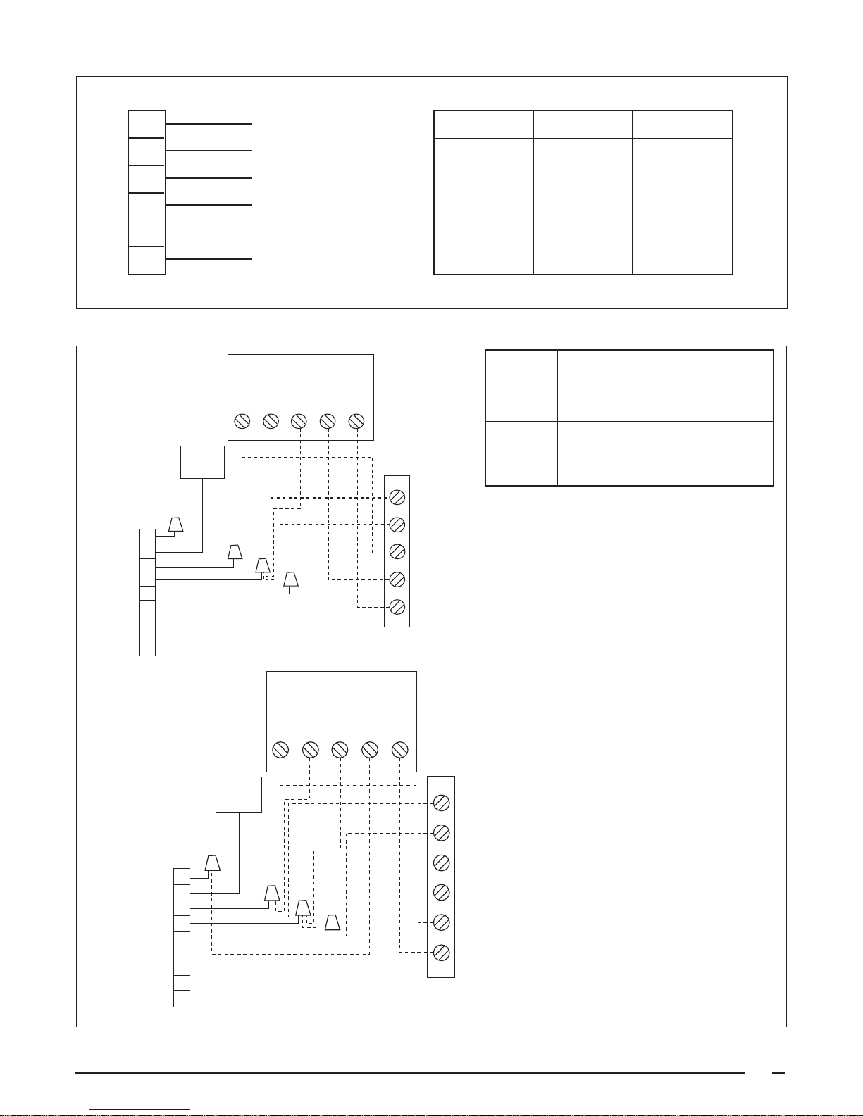
1
Y
1
1
RED
PIN NUMBER
WIRE COLOR
MOTOR SPEED
2
3
4
5
6
ECONOMIZER
PLUG
Green
1
Gray
2
Black
3
ellow
4
Blue
5
6
7
8
Typical Wiring (Field Supplied) for 1-Stage Cool, 1-Stage Heat
9
Gas
Valve
ORANGE
BLUE
BLACK
WHITE
(Not Used on
3 Speed Motors)
Figure 8. Indoor Blower Motor Leads.
FURNACE BOARD
R C Y G W
1
2
3
4
5
6
RED
ORANGE
BLUE
BLACK
N/A
WHITE
Recommended T’stat
T’stat Wire Length Ft. (Unit to T'stat)
Wire 2-wire 4/5-wire
Gauge (Heating) (Cooling/HP)
24 55 25
22 90 45
20 140 70
18 225 110
(Optional, Check thermostat Instructions)
X
Y
R
G
W
INDOOR
THERMOSTAT
SUB-BASE
LOW
MED LOW
MED HIGH
or MEDIUM
HIGH
N/A
COMMON
FURNACE BOARD
R C Y G W
Gas
Valve
ECONOMIZER
PLUG
Green
1
Gray
2
Black
3
Yel lo w
4
Blue
5
6
7
8
Typical Wiring (Field Supplied) for 2-Stage Cool, 1-Stage Heat
9
Figure 9. Typical Thermostat Connections.
(Optional, Check thermostat Instructions)
X
Y2
INDOOR
THERMOSTAT
Y1
SUB-BASE
R
G
W1
17
Page 18

FAULT CONDITION STATUS LIGHT (RED
Power On On
Limit Circuit Open 1 Flash
Pressure Switch Stuck Open
with Inducer On
2 Flash
Pressure Switch Stuck Closed
with Inducer Off
3 Flash
Ignition Failure (Check Ground) 4 Flash
230 VAC & Neutral Reversed
or No Ground
5 Flash
False Flame or Gas Relay Shorted
Continuous Flash
Power Off Off
FAULT CONDITION STATUS LIGHT (YELLOW)
Low Flame Sensor Signal Continuous Flash
Flame Present On
BLOWER
MOTOR
RED
ORANGE
T2
T1
G
GREEN-YELLOW
WHITE
7105850
RELAY
RED
BLUE
T3
T4
T5
C
L
N
RED
XFMRL1EAC
INDUCER
RELAY
RED
COOL
M3M2M1
HEAT
HUM
R
C
2
1
2
1
BLACK
BLACK
BROWN
BROWN
4
215
3
6
HUM
EAC
S
NEUTRAL
7
1
4
2
8
5
9
3
6
24V
COM
RCYGW
WHITE
1
1
WHITE
BROWN
YELLOW
IGNITOR
2
2
RED
ORANGE
PRESSURE
SWITCH
ORANGE
GAS
FLAME
GREEN
VALVE
SENSOR
TO THERMOSAT
Y
C
R
G
Y2
W1
GROUND
BLUE
FLAME
SWICH
ROLL-OUT
BLUE
LIMIT
SWITCH
BLUE
RED
BLACK
RED
WHITE
BLUE
TO 208/230 VAC
POWER SUPPLY
BLACK
HEATER
CRANKCASE
(IF EQUIPPED)
BLACK
CONTACTOR
COMPRESSOR
L1
L2
BLACK
RED
BLACK
T2 T1
COM
24V
240V
LOCATION
PROVIDED
GROUND ON
PRESSURE
208V
ORANGE
WHITE
INSIDE
COMPRESSOR
TERMINAL BOX
YELLOW
YELLOW
BLACK
SWITCH (44)
IF EQUIPPED
BLUE
GREY
BLACK
GREEN
YELLOW
ORANGE
BLUE
ORANGE
YELLOW
34567
34567
BLACK
YELLOW
34567
34567
8
R
C
R
C
BLACK
BLUE
S
FAN M OTOR
CHF
DUAL CAPACITOR
S
RED
COMPRESSOR OUTDOOR
RED
RED
AIR SENSOR
TO DISCHARGE
9
8
9
RED
RED
8
9
8
9
2
2
GREY
2
2
1
1
GREEN
1
1
PLUG
ECONOMIZER
8-WIRE
HARNESS ASSY
ECONOMIZER JUMPER
PLUG
ECONOMIZER
Factory Wiring
Low Voltage
Field Wiring
High Voltage
18
servicing.
copper conductors only.
exceed 150 V to ground.
supplied with the furnace must be
replaced, it must be replaced with
wiring material having a temperature
rating of at least 105°C.
overcurrent protection, see unit
rating plate.
1. Disconnect all power before
2. For supply connections use
3. Not suitable on systems that
N NOTES:
4. If any of the original wire as
5. For supply wire ampacities and
1. Couper le courant avant de faire
Figure 10. Single-Phase Wiring Diagram.
letretien.
conducteurs en cuivre.
de plus de 150 V a la terre.
2. Employez uniquement des
3. Ne convient pas aux installations
WD# 7105850
Page 19

the registers or in the ductwork. Set thermostat fan switch
!
to “Auto,” the blower will shut down in 60 seconds.
Short Cycle Protection — For single phase units only,
with the system operating in cooling mode, note the
temperature setting of the thermostat and gradually raise
the set-point temperature until the unit de-energizes.
Immediately lower the set point temperature of the
thermostat to its original setting and verify that the indoor
blower is energized. Verify that after approximately 5
minutes the compressor and fan energize and that the
temperature of the discharged air is cooler than the room
temperature.
System Cooling
1. Set the thermostat system switch to “Cool” and the
thermostat fan switch to “Auto.” Gradually lower the
thermostat temperature switch below room
temperature and observe that the blower, compressor
and fan energize. Check that air cooler than room
temperature is being discharged at the register.
Listen for any unusual noises. Locate the source
and correct as needed.
2. After allowing the unit to run for several minutes, set
the temperature selector above room temperature,
verify that:
a. The fan and compressor cycle off with the
thermostat.
b. The blower also stops after the 90 second
delay.
System Heating
1. Set the thermostat to the lowest setting.
2. Follow the procedures given on the operating
instruction label, in this installation instructions or
attached inside the louvered control access panel.
3. Set the thermostat above room temperature and
verify the sequence of operation. (See Operating
Sequence on page 25.)
4. Verify that the compressor and outdoor fan motor are
not energized.
5. After the unit has run for approximately five minutes,
set the thermostat below room temperature and
verify the shutdown sequence. (See Operating
Sequence on page 25.)
Verifying and Adjusting Firing Rate — The firing rate
must be verified for each installation to prevent over-firing
of the furnace.
IMPORTANT NOTE: The firing rate must not exceed the
rate shown on the unit data label. At altitudes above
2,000 ft. it must not exceed that on the data label less
4% for each 1,000 ft.
Follow the procedure below to determine the firing rate:
1. Shut off all other gas fired appliances.
2 Start the unit in heating mode and allow it to run for
at least three minutes.
3. Measure the time (in seconds) required for the gas
meter to complete one revolution.
4. Convert the time per revolution to cubic feet of gas
per hour using Table 8.
5. Multiply the gas flow rate in cubic feet per hour by the
heating value of the gas in Btu per cubic foot to obtain
the firing rate in Btu per hour. Example:
a. Time for one revolution of a gas meter with a
one cubic foot dial = 40 seconds.
b. From Table 8 read 90 cubic feet per hour of gas.
c. Heating value of the gas (obtained from gas
supplier) = 1040 Btu per cubic foot.
d. Firing rate = 1040 x 90 = 93,600 Btuh.
6. Adjustments to the firing rate can be made by
adjusting the gas manifold pressure. See the High
Altitude Application section for additional information
of firing rate at elevations above 2000 ft.
The manifold pressure must be set to the appropriate value
for your installation. Refer to either Table 5 for natural gas or
Table 6 for LP/propane gas to verify the manifold pressure
setting required for your particular installation. To adjust the
manifold pressure, remove the regulator cap and turn the
adjusting screw clockwise to increase pressure or counterclockwise to reduce pressure. Replace the regulator cap
after adjustments are complete.
Verifying and Adjusting Temperature Rise — Verify that
the temperature rise through the unit is within the range
specified on the unit data label. Temperature rises outside
the specified range could result in premature heat exchanger
failure.
Place thermometers in the return and supply air stream as
close to the duct connections as possible. The thermometer
on the supply air side must be shielded from direct radiation
from the heat exchanger to avoid false readings. Adjust
all registers and duct dampers to the desired position and
run the unit for ten to fifteen minutes before taking any
temperature readings. The temperature rise is the difference
between the supply and return air temperatures.
CA UTION:
Do not re-drill the burner orifices. If the orifice
size must be changed, use only new orifices.
For typical duct systems, the temperature rise will fall
within the range specified on the data label with the blower
speed at the factory recommended setting (see Table 3).
If the temperature rise measured is outside the range
19
Page 20

FOR YOUR SAFETY
I
I
Manifold
et
READ BEFORE OPERATING
POUR VOTRE SÉCURITÉ.
À LIRE A V ANT L ’EMPLOI
WARNING: If you do not follow these
instructions exactly, a fire or explosion may
result causing property damage, personal
injury, or loss of life.
A . This appliance does not have a pilot. It is equipped with an
ignition device which automatically lights the burner. Do
to light the burner by hand.
B. BEFORE OPERATING smell all around the appliance area for
gas. Be sure to smell next to the floor because some gas is
heavier than air and will settle on the floor.
WHAT TO DO IF YOU SMELL GAS
• Do not try to light any appliance.
• Do not touch any electrical switch; do not use any phone in
your building.
• Immediately call your gas supplier from a neighbor’s phone.
Follow the gas supplier’s instructions.
• If you cannot reach your gas supplier, call the fire department.
C. Use only your hand to push in or turn the gas control knob.
Never use tools. If the knob will not push in or move by hand,
do not try to repair it, call a qualified service technician. Force
or attempted repair may result in a fire or explosion.
D. Do not use this appliance if any part has been under water.
Immediately call a qualified service technician to inspect the
appliance and to replace any part of the control system and
any gas control which has been under water.
not try
ATTENTION! L’inobservation de ces
instructions peut entraîner un incendie ou une
explosion pouvant causer des dammages à
votre propriété à votre personne, ou la mort.
A . Cet appareil ménager n'a pas de veilleuse. II est doté d’un
système d’allumage automatique. Ne pas essayer d'allumer le
brûleur manuellement.
B. AVANT L’USAGE. Attention à une possible odeur de gaz
surtout au niveau du plancher où les gaz les plus lourds ont la
tendance de se concentrer.
EN CAS D’ODEUR DE GAZ.
• Ne mettre en marche aucun appareil électrique.
• Ne toucher à aucun commutateur électrique, ne pas employer le
téléphone.
• Quitter le bâtiment immédiatement et avertir la compagnie du
gaz en utili sant le téléphone d'un voisin.
• A défaut de la compagnie du gaz, avertir le service des
pompiers.
C. Enfoncer ou faire tourner le robinet à gaz à la main seulement. Ne
jamais utiliser d'outils. S’il n’est pas possible de faire tourner ou
d’enfoncer le robinet à la main, ne pas essayer de le réparer. Faire
appel à un spécialiste. Forcer ou tenter de réparer le robinet
pourrait être à l’origine d’une explosion ou d’un incendie.
D. II est déconseillé d’utiliser cet appareil en contact prolongé avec
l’eau. Faire inspecter ou remplacer toute commande par un
technicien qualifié si un des systèmes de contrôle du gaz s'est
trouvé sous l'eau.
OPERATING INSTRUCTIONS
1. STOP! Read the safety information above on this label.
2. Set the thermostat to the lowest setting.
3. Turn off all electrical power to the appliance.
4. The appliance’s ignition device automatically lights the burner.
Do not try to light burner by hand.
5. Remove the control access door/panel (upper door if two-door
model).
6. Move the gas control knob clockwise to “OFF”.
(See Figure 11)
7. Wait five (5) minutes to clear out any gas. Then smell for
gas, including near the floor. If you smell gas, STOP! Follow “B”
in above information. If you don’t smell gas, go to the next step.
8. Move the gas control knob counterclockwise to “ON”.
(See Figure 11)
9. Replace the control access door/panel
(upper door if two-door model).
10. Turn on all electrical power to
the appliance.
11. Turn the thermostat to a desired
setting.
12. If the appliance will not
operate, follow the instructions
“To Turn Off Gas To Appliance”
and call your service technician or gas supplier.
KNOB
(ROBINET)
nlet Pressure Tap
nlet
Figure 11
Protective
Cap
On/Off Lever
Pressure Tap
1. ATTENTION! Lire d'abord la liste des mesures de sécurité cidessus.
2. Mettre le thermostat à la position minimale.
3. Couper le courant électrique qui mène à l’appareil.
4. Cet appareil ménager étant doté d’un système d’allumage
automatique, ne pas essayer d'allumer le brûleur manuellement.
5. Retirer le panneau/volet d’accès de commande (panneau
supérieur s’il s’agit d’un modèle à deux panneaux).
6. Faire tourner le robinet à gaz dans le sens des aiguilles d’une
montre pour l’amener sur la position OFF (Arrêt) (Voir
Figure 11).
7. Attendre cinq (5) minutes pour s’assurer de la dissipation du gaz
En cas d’odeur, ARRÊTER LE PROCÉDÉ. Suivre les instructions ci-dessus (Section B). En l’absence de toute odeur de
gaz, avancer à l’étape suivante.
Faire tourner le robinet à gaz dans le sens inverse des aiguilles
8.
d’une montre pour l’amener sur la position ON (Marche)
(Voir Figure 11).
9. Remettre le panneau/volet d’accès de commande en place
(panneau supérieur s’il s’agit d’un modèle à deux panneaux).
10. Rebrancher l’appareil sur le réseau électrique.
Outl
11. Ajuster le thermostat à la position désirée.
12. Si l’appareil ne fonctionne pas, suivre les “Directives d’arrêt”
cidessous et appeler le technicien de service.
MODE D'EMPLOI
TO TURN OFF
GAS TO APPLIANCE
1. Set the thermostat to the lowest setting.
2. Turn off all electrical power to the appliance if service is to
be performed.
3. Remove the control access door/panel (upper door if twodoor model).
4. Move the gas control knob clockwise to “OFF”. Do
not use force. (See Figure 11)
5. Replace the control access door/panel (upper door if twodoor model).
1. Mettre le thermostat à la position minimale.
2. Débrancher l’appareil en prévision de la réparation.
3. Retirer le panneau/volet d’accès de commande (panneau
supérieur s’il s’agit d’un modèle à deux panneaux).
4. Faire tourner le robinet à gaz dans le sens des aiguilles d’une
montre pour l’amener sur la position OFF (Arrêt) Ne
pas forcer (Voir Figure 11).
5. Remettre le panneau/volet d’accès de commande en place
(panneau supérieur s’il s’agit d’un modèle à deux panneaux).
DIRECTIVES D’ARRÊT
Page 21

!
!
specified, it may be necessary to change the blower speed.
!
Lower blower speeds will increase the temperature rise and
higher blower speeds will decrease the temperature rise.
The unit is equipped with a multi-speed motor. Heating and
cooling speed selection is made by moving the leads on the
integrated control located in the unit control box. The wiring
diagram on the unit and in Figure 10 show the speed taps
for adjusting motor speed. Refer to the Blower Speed
Section of this installation instruction for more details.
The integrated control is designed to start the circulating air
blower 30 seconds after the gas valve is opened. The
integrated control is factory wired to turn the blower motor
off 120 seconds after the gas valve is closed.
COMPONENT FUNCTIONS
Flame Sensor — The flame sensor acts to prove that
flame has carried over from the ignitor to the right-most
burner. If no flame is sensed, the unit will be shut down
automatically.
Flame Roll-Out Control — The flame roll-out control acts
to verify that the burner flame is being drawn into the heat
exchanger tubes. If the burner flame is not being drawn into
the heat exchanger tubes, the roll-out control will open
within several seconds and the integrated control diagnostic
light will flash one time. The circulating air blower and
combustion blower will continue to operate if the flame rollout control opens.
Verifying Burner Operation — To verify operation of the
burners remove the louvered control access panel to
ensure there is power to the unit. Set the thermostat to a
temperature above room temperature and observe the
ignition sequence. The burner flame should carry over
immediately between all burners. The flames should be
blue, without yellow tips. Flames should extend from each
burner without lifting off, curling, or floating. After verifying
satisfactory flame characteristics, set the thermostat to a
temperature below room temperature and verify that the
burner flame extinguishes completely.
WARNING:
Uninsulated live components are exposed when
louvered control access panel is removed.
Verify Operation of Over-Temperature Limit Control –
To verify operation of the over-temperature limit control,
make sure that the louvered control access panel is in
place and that there is power to the unit. Block the return
airflow to the unit by installing a close-off plate in place of
or upstream of the filter. Set the thermostat to a temperature
above room temperature and verify the unit operates with
the correct sequence of operation (see page 25). The overtemperature limit control should function to turn off the gas
valve within approximately four minutes (the exact time
depending on the efficiency of the close-off in blocking the
return air to the unit). The circulating air and combustion
blowers should continue to run when the over-temperature
limit control switch opens. Remove the close-off immediately
after the over-temperature limit control opens. If the unit
operates for more than four minutes with no return air, set
the thermostat to a temperature below room temperature,
shut off the power to the unit, and replace the overtemperature limit control.
Gas Valve — The gas valve acts to control the flow of gas
to the burners. When the gas valve is energized it
automatically opens and regulates the gas pressure in the
manifold.
Pressure Switch — The pressure switch acts to verify that
the inducer motor is drawing the combustion gases through
the heat exchanger tubes and venting the gases through
the vent system.
Over-Temperature Limit Control — The over-temperature
limit control acts to prevent the air temperature leaving
the unit from exceeding the maximum outlet air
temperature. If the limit opens, the integrated control
diagnostic will flash one time. The circulating air blower
and combustion blower will continue to operate if the
over-temperature limit control opens.
UNIT MAINTENANCE
WARNING:
To avoid risk of electrical shock, personal injury,
or death, disconnect all electrical power to the
unit before performing any maintenance or
service. The unit may have more than one
electrical supply.
CAUTION:
Use care when removing parts from this unit.
Personal injury can result from sharp metal edges
present in all equipment of sheet metal
construction.
21
Page 22

Refrigerant Charging — The packaged gas/electric units
!
!
are fully charged at the factory. The system refrigerant
charge can be checked and adjusted through the service
ports provided behind the service panel. Use only gauge
lines which have a “Schrader” depression device present to
actuate the valve. Refrigerant charging must be done by
qualified personnel familiar with safe and environmentally
responsible refrigerant handling procedures.
WARNING:
The gas/electric units are shipped fully charged
and ready for installation. When a system is
installed according to these instructions, no
refrigerant charging is required. If repairs make
it necessary for evacuation and charging, it
should only be done by qualified, trained
personnel thoroughly familiar with this
equipment. Some local codes require licensed
installation/service personnel to service this type
of equipment. Under no circumstances should
the owner attempt to install and/or service this
equipment. Failure to comply with this warning
could result in property damage, personal injury,
or death.
Routine Maintenance — Proper maintenance is important
to achieve optimum performance from the air conditioner.
The ability to properly perform maintenance on this equipment
requires certain mechanical skills and tools.
If you do not possess these skills, contact your dealer for
maintenance. Consult your local dealer about the availability
of maintenance contracts. At a minimum, routine
maintenance should include the following:
Air Filter — Inspect and clean or replace the air filter
every three to four weeks.
WARNING:
Never operate the unit without a filter in place.
Dust and lint in the return air can build up on
internal components, resulting in loss of
efficiency, equipment damage, and possible fire
risk.
Vent Cover Assembly — Inspect and clean the screen of
the vent cover assembly at the beginning of each heating
and cooling seasons.
Condensate Drain and Outdoor Coil — Inspect the
condensate drain and outdoor coil at the beginning of each
cooling season. Remove any debris. Clean the outdoor coil
GAS FLOW RATE (CUBIC FEET PER HOUR)
TIME FOR TIME FOR
ONE REVOL UTION ONE REVOL UTION
(SECONDS) 1 5 10 (SECONDS) 1 5 10
10 360 1800 3600 66 55 273 545
12 300 1500 3000 68 53 265 529
14 257 1286 2571 70 51 257 514
16 225 1125 2250 72 50 250 500
18 200 1000 2000 74 49 243 486
20 180 900 1800 76 47 237 474
22 164 818 1636 78 46 231 462
24 150 750 1500 80 45 225 450
26 138 692 1385 82 44 220 439
28 129 643 1286 84 43 214 429
30 120 600 1200 86 42 209 419
32 113 563 1125 88 41 205 409
34 106 529 1059 90 40 200 400
36 100 500 1000 92 39 196 391
38 95 474 947 94 38 191 383
40 90 450 900 96 38 188 375
42 86 429 857 98 37 184 367
44 82 409 818 100 36 180 360
46 78 391 783 102 35 176 353
48 75 375 750 104 35 173 346
50 72 360 720 106 34 170 340
52 69 346 692 108 33 167 333
54 67 333 667 110 33 164 327
56 64 321 643 112 32 161 321
58 62 310 621 114 32 158 316
60 60 300 600 116 31 155 310
62 58 290 581 118 31 153 305
64 56 281 563 120 30 150 300
CUBIC FEET PER REVOLUTION OF METER
CUBIC FEET PER REVOLUTION OF METER
22
Table 8. Gas Flow Rate (Cubic Feet Per Hour).
Page 23

and hail guard louvers (optional) as necessary using a mild
!
!
!
detergent and water. Rinse thoroughly with water.
Electrical — Inspect the electrical connections for tightness
at the beginning of each heating and cooling season.
Service as necessary.
CA UTION:
Label all wires prior to disconnection when
servicing controls. Wiring errors can cause
improper and dangerous operation.
Motor Lubrication — The motors for the circulating air
blower, outdoor fan, and combustion blower are prelubricated at the factory. No further oiling is required for the
life of this product.
WARNING:
Lubrication of the motors in this unit is not
required. Do not lubricate any motor in this
product.
Blower Compartment — The blower compartment should
be cleaned monthly during the heating and cooling seasons
to remove any dirt and lint that may have accumulated in
the compartment or on the blower and motor. Buildup of dirt
and lint on the blower and motor can create excessive loads
on the motor resulting in higher than normal operating
temperatures and possible shortened service life.
Cleaning of Heat Exchanger — If the heat exchanger
must be cleaned due to soot or scale build up, follow the
steps below.
1. Shut off the gas supply to the unit either at the meter
or at the manual valve in the gas supply piping.
2. Turn off all power to the unit and set the thermostat
to the lowest temperature setting.
3. Remove the louvered control access panel from the
unit.
4. Turn the gas control knob on the gas valve to the
“OFF” position.
5. Disconnect the wires from the gas valve, ignitor,
flame sensor, combustion air motor, flame roll-out
control, over-temperature limit switch, and pressure
switch.
6. Remove the silicone rubber tube from the collector
pan to the pressure switch.
7. Remove the four nuts that hold the combustion
blower to the collector pan and remove the complete
combustion blower.
8. Remove the screws that hold the collector pan in
place, and remove the collector pan from the unit.
9. Using wrenches, separate the ground-joint union in
the gas supply piping at the unit.
Heat Exchanger and Burner Maintenance — The unit
should operate for many years without excessive scale
buildup in the heat exchanger, however, the heat exchanger,
the vent system, and the burners should be inspected and
cleaned (if required) by a qualified serviceman annually to
ensure continued safe operation. Particular attention must
be given to identify deterioration from corrosion or other
sources.
WARNING:
Holes in the heat exchanger can cause products
of combustion to enter the home. Replace the
heat exchanger if leaks are found. Failure to
prevent products of combustion from being
circulated into the living space can create
potentially hazardous conditions including
carbon monoxide poisoning that could result in
personal injury or death.
10. Remove the piping between the gas valve and the
ground-joint union, if necessary.
11. Remove the screws that hold the burner assembly in
place and remove the burner assembly. BE
EXTREMELY CAREFUL NOT TO DAMAGE THE
IGNITOR WHILE REMOVING THE BURNER
ASSEMBLY.
12. The unit heat exchanger tubes can now be cleaned
by the use of a round wire brush attached to a length
of high grade stainless steel cable, such as drain
cleanout cable. Attach variable speed reversible drill
to the other end of the spring cable. Slowly rotate the
cable with the drill and insert it into the top portion of
the heat exchanger. While reversing the drill, work
the cable in and out several times to obtain sufficient
cleaning. Repeat this sequence for each heat
exchanger tube.
23
Page 24

13. When all heat exchanger tubes have been cleaned,
!
any debris inside the tubes can be removed with the
nozzle of a vacuum cleaner.
14. With a light, check the condition of the upper and
lower sections of the heat exchanger tube.
10. Replace all the parts in reverse order from which they
were removed.
11. Follow the lighting instructions found on the lower
unit door to return the unit to operation.
15. Inspect the burners and clean them (if necessary)
with a soft wire brush and/or the nozzle of a vacuum
cleaner. BE EXTREMELY CAREFUL NOT TO
DAMAGE THE IGNITOR WHILE CLEANING THE
BURNER.
16. Replace all the parts in reverse order from which they
were removed.
17. Follow the operating instructions found on the right
side door and the User’s Information Manual to return
the unit to operation.
Cleaning of Burners — If the burners must be cleaned,
follow the steps below.
1. Shut off the gas supply to the unit either at the meter
or at a manual valve in the supply piping.
2. Turn off all power to the unit and set the thermostat
to the lowest temperature setting.
3. Remove the louvered control access panel from the
unit.
4. Turn the gas control knob to the “OFF” position.
5. Disconnect the wires from the gas valve, ignitor, and
flame sensor.
CA UTION:
Verify proper operation after servicing.
Operating Sequence
The operating sequences for the heating, cooling, and fan
modes are described below. Refer to the wiring diagram for
the unit (Figure 10).
Cooling Mode:
1. On a call for cooling the thermostat closes, applying
24 VAC to the green and yellow leads in the low
voltage area.
2. The green lead applies 24VAC to the “G” terminal of
the integrated control energizing the main circulating
blower circuit at the cooling speed.
3. The yellow lead applies 24VAC to the anti-short
cycle timer if installed and then to the contactor.
4. When the thermostat is satisfied the contactor and
integrated control are de-energized.
5. The circulating blower motor is de-energized after a
90-second delay.
Blower Mode:
6. Using wrenches, separate the ground-joint union in
the gas supply piping at the unit.
7. Remove the piping between the gas valve and the
ground-joint union, if necessary.
8. Remove the screws that hold the burner assembly in
place and remove the burner assembly. BE
EXTREMELY CAREFUL NOT TO DAMAGE THE
IGNITOR WHILE REMOVING THE BURNER
ASSEMBLY.
9. Inspect the burners and clean them (if necessary)
with a soft wire brush and/or the nozzle of a vacuum
cleaner. BE EXTREMELY CAREFUL NOT TO
DAMAGE THE IGNITOR WHILE CLEANING THE
BURNER.
24
1. On a call for fan operation, the thermostat applies 24
VAC to the green lead connected to the “G” terminal
of the integrated control.
2. The circulating blower is energized immediately at
the heating speed.
3. If a call for heat occurs, the circulating blower deenergizes prior to normal heating cycle.
Heating Mode:
1. On a call for heat the thermostat closes, applying 24
VAC to the “W” terminal on the integrated control.
2. The integrated control monitors the safety circuit at
all times. If either the roll-out control or the overtemperature limit control opens, both the main
Page 25

blower and combustion blower will continue to run
until the circuit closes. After the safety circuit
closes the main blower and blower will run for a
specified post purge time.
3. The integrated control checks the pressure switch
at the beginning of the heating cycle. If it is closed,
the inducer will run 30 seconds, the control will go
into lock out, and the diagnostic light will flash three
times. If it is open, it will start the inducer motor.
12. After the “blower off” timer has been satisfied, the
integrated control de-energizes the main circulating
blower circuit.
13. If the unit fails to prove ignition after five attempts,
it will go into soft lockout. The unit will re-attempt the
start-up procedure every hour until the thermostat is
satisfied.
Unit Fails to Operate
4. The inducer motor starts and closes the pressure
switch. If the pressure switch does not close in 10
seconds the integrated control will go into lock out
and the diagnostic light will flash two times.
5. The inducer will prepurge for 30 seconds and the
igniter will start the warm up cycle as follows.
Initial Power up: After 30 seconds of igniter warmup the gas valve (24 VAC) will then open. The igniter
circuit will stay energized for 3 seconds after the gas
valve opens.
After Initial Power up: The control has a programmed
adaptive ignition feature which varies the warm-up
period as follows: If ignition is successful the warmup is reduced by 3-seconds on each subsequent
call for heat until ignition failure occurs. Upon ignition
failure, the warm-up is increased by 3-seconds on
the next try. If successful, the timing remains fixed
at this level. In general, whenever ignition failure
occurs the warm-up interval is increased by 3seconds on the next try. And if successful, it
remains there. Min. and max. warm-up time limits
are set at 6 and 54-seconds, respectively.
6. The flame must be proven through the flame sensor
in five seconds to hold the gas valve open. The
integrated control will monitor the gas flame with the
flame sensor for the entire time the gas valve is
open. If for any reason the gas flame drops out the
gas valve will immediately close.
7. 30 seconds from the gas valve opening the main
blower starts and continues to run.
8. When the thermostat is satisfied, the “W” terminal on
the integrated control is de-energized.
9. The gas valve circuit is de-energized and the gas
valve closes.
10. The inducer motor will continue to run for the post
purge period of 25 seconds.
11. The main blower will continue to run for the blower off
delay of 120 seconds.
If the unit does not operate in the cooling mode, be certain
to check the following:
1. The thermostat is operating properly.
2. Electrical power to the unit is turned on.
3. The filters are not dirty.
4. The service doors are in place.
5. The 3 amp fuse is operational.
6. The anti-short cycle timer’s 5-minute cycle has
finished for single phase units.
If the unit does not operate in the heating mode, be certain
to check the following:
1. The thermostat is operating properly.
2. Electrical power to the unit is turned on.
3. The filters are not dirty.
4. The gas is turned on.
5. The manual shut-off valve is open.
6. The service doors are in place.
7. The flame roll-out control is closed.
8. Refer to the diagnostic code table on the wiring
diagram or see Table 9.
9. The 5 amp fuse is operational.
FAULT
CONDITION
Power On On
Limit Circuit Open 1 Flash
Pressure Switch Stuck Open 2 Flash
Pressure Switch Stuck Closed 3 Flash
Ignition Failure (Check Ground) 4 Flash
230 VAC & Neutral Reversed or No Ground 5 Flash
False Flame or Gas Relay Shorted Continuous Flash
Power Off Off
FAULT
CONDITION
Low Flame Sensor Signal Continuous Flash
Flame Present On
Table 9. Diagnostic Codes.
STATUS
LIGHT (RED)
STATUS LIGHT
(YELLOW)
25
Page 26

INSTALLATION/PERFORMANCE CHECK LIST
LOCATION ____________________________ CITY _____________________________ STATE _______
INSTALLER____________________________ CITY _____________________________ STATE _______
UNIT MODEL NUMBER __________________ UNIT SERIAL NUMBER ______________
Minimum Clearances per Table 1?_________________
Electrical Connections tight? _____________________
Supply Voltage: ________________ Volts
Blower Motor H.P.: _____________
FUEL TYPE:
Natural Gas ____________ LP/Propane _______
Gas Piping Connections leak-tested? ___________
Gas Line Pressure: _____________
(in. water column, with furnace operating)
Manifold Pressure: _____________
(in. water column, with furnace operating)
Is the vent hood installed?_______________________
Is there Proper Draft? __________________________
Is vent hood free from restrictions? ________________
Is the Filter(s) clean? ___________________________
Has the Thermostat been calibrated? ______________
Is the Thermostat level? ________________________
Is the Heat Anticipator Setting correct? _____________
Has the Owner's Information been reviewed with the
homeowner? _________________________________
Is there adequate fresh air supply for combustion and
ventilation? _______________
Furnace Input: ____________________ Btu/hr)
Supply Air Temperature: ____________ (°F)
Return Air Temperature:_____________ (°F)
Temperature Rise: _________________ (°F)
26
Has the Literature Package been left with the
homeowner? _________________________________
Page 27

27
Page 28

INSTALLER: PLEASE LEAVE
THESE INSTALLATION
INSTRUCTIONS WITH THE
HOMEOWNER.
O’Fallon, MO
¢708531«¤
708531A
708531A (Replaces 7085310)
Specifications and illustrations subject to change
without notice and without incurring obligations.
Printed in U.S.A. (03/06)
 Loading...