

Nordyne P6, R6GD-X36, P6SD-X36, P6SD-X48, Q6SD-X36 Installation Manual
P6 Series
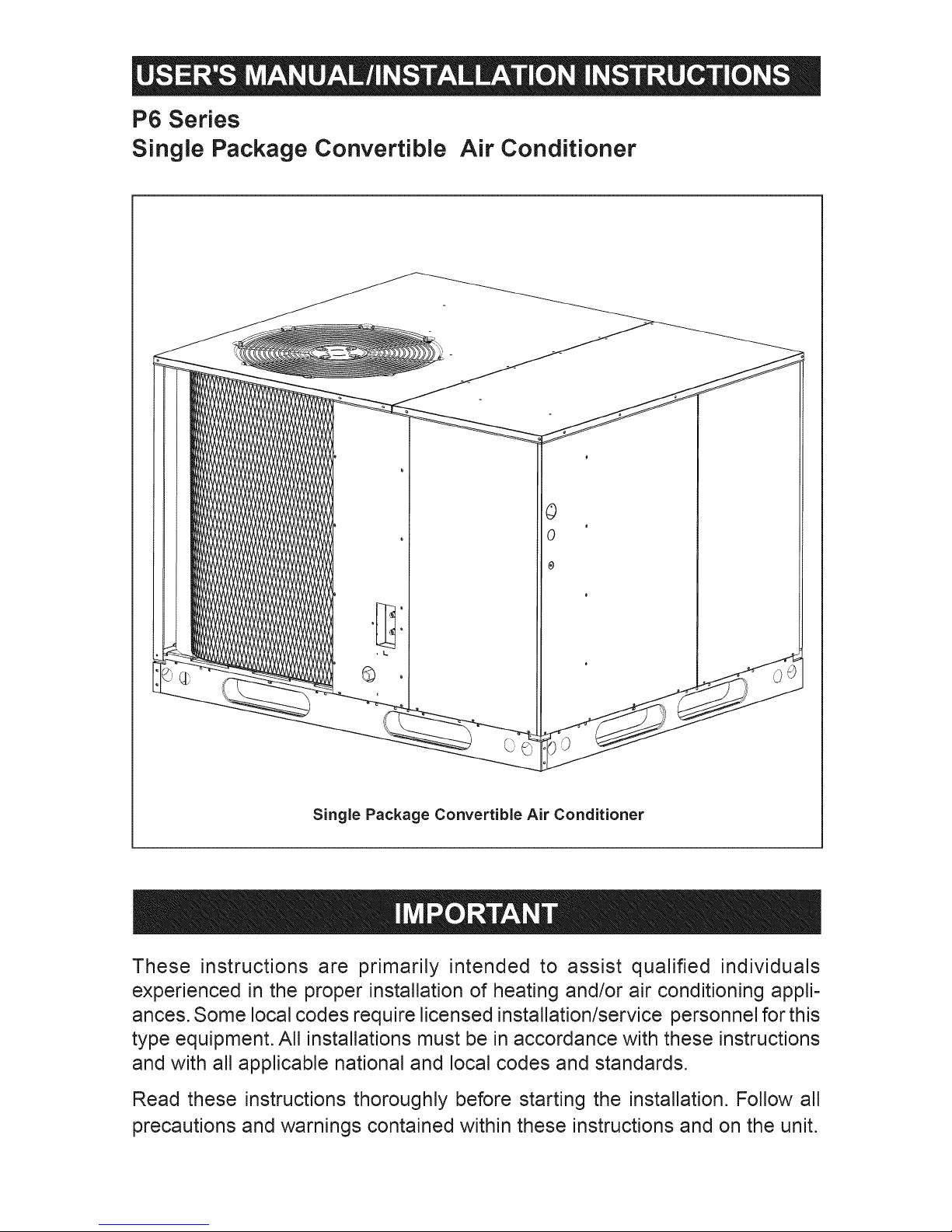
Single Package Convertible Air Conditioner
Single Package Convertible Air Conditioner
These instructions are primarily intended to assist qualified individuals
experienced in the proper installation of heating and/or air conditioning appli-
ances. Some local codes require licensed installation/service personnel for this
type equipment. All installations must be in accordance with these instructions
and with all applicable national and local codes and standards.
Read these instructions thoroughly before starting the installation. Follow all
precautions and warnings contained within these instructions and on the unit.

TABLE OF CONTENTS
OWNER INFORMATION ............................................................................................................... 4
OPERATING INSTRUCTIONS ...................................................................................................... 4
GENERAL SPECiFiCATiONS ...................................................................................................... 5
SAFETY CONSiDERATiONS ....................................................................................................... 5
Literature, Labels, and Tags .................................................................................................. 5
Pressures Within The System ............................................................................................... 5
iNSTALLATiON REQUIREMENTS ............................................................................................... 5
Equipment Check ................................................................................................................. 5
Requirements and Codes ..................................................................................................... 5
Unit Dimensions ................................................................................................................... 6
Unit Location ......................................................................................................................... 7
Air Filter Requirements ......................................................................................................... 7
internal Air Filter Assembly Removal .................................................................................... 8
Condensate Drain ................................................................................................................. 8
UNIT iNSTALLATiON ................................................................................................................... 8
Ground Level ........................................................................................................................ 8
Rigging and Hoisting ............................................................................................................ 8
Rooftop ................................................................................................................................. 9
AIR SUPPLY ................................................................................................................................. 9
Unconditioned Spaces ........................................................................................................ 10
Acoustical Ductwork ........................................................................................................... 10
Horizontal to Down Flow Conversion .................................................................................. 10
Clearance ........................................................................................................................... 10
ELECTRICAL WIRING ................................................................................................................ 10
General ............................................................................................................................... 10
Line Voltage ........................................................................................................................ 10
Blower Speed ..................................................................................................................... 11
Room Thermostat .......................................................................................................... 11-13
WiRiNG DIAGRAM ..................................................................................................................... 12
SYSTEM CHECK ........................................................................................................................ 13
Pre-Start Check List ........................................................................................................... 13
START-U P PROC EDU RE ........................................................................................................... 13
Air Circulation ..................................................................................................................... 13
System Cooling .................................................................................................................. 13
System Heating .................................................................................................................. 13
UNIT MAINTENANCE ................................................................................................................. 13
Refrigerant Charging .......................................................................................................... 13
Routine Maintenance .......................................................................................................... 14
installation / Removal of Air Filters ..................................................................................... 14
Package A/C Blower Curves .............................................................................................. 15
Refrigerant Charging Charts ......................................................................................... 15-16
Wiring Diagrams ............................................................................................................ 17-18
OWNER INFORMATION
OPERATING INSTRUCTIONS
To OperateYour Air Conditioner for Cooling =
1. Set the thermostat system switch to COOL or
AUTO and the thermostat fan switch to AUTO.
(See Figure 1)
2. Set the thermostat temperature to the desired
temperature level using the temperature selector.
Please refer to the separate thermostat user's
manual for complete instructions regarding
thermostat programming. The outdoor unit
and indoor blower will both cycle on and off to
maintain the indoor temperature at the desired
cooling level.
To OperateYou r Unit for Heatin g = (If optional
heat accessory is installed.)
1. Set the thermostat system switch to HEAT or
AUTO and the thermostat fan switch to AUTO.
(See Figure 1)
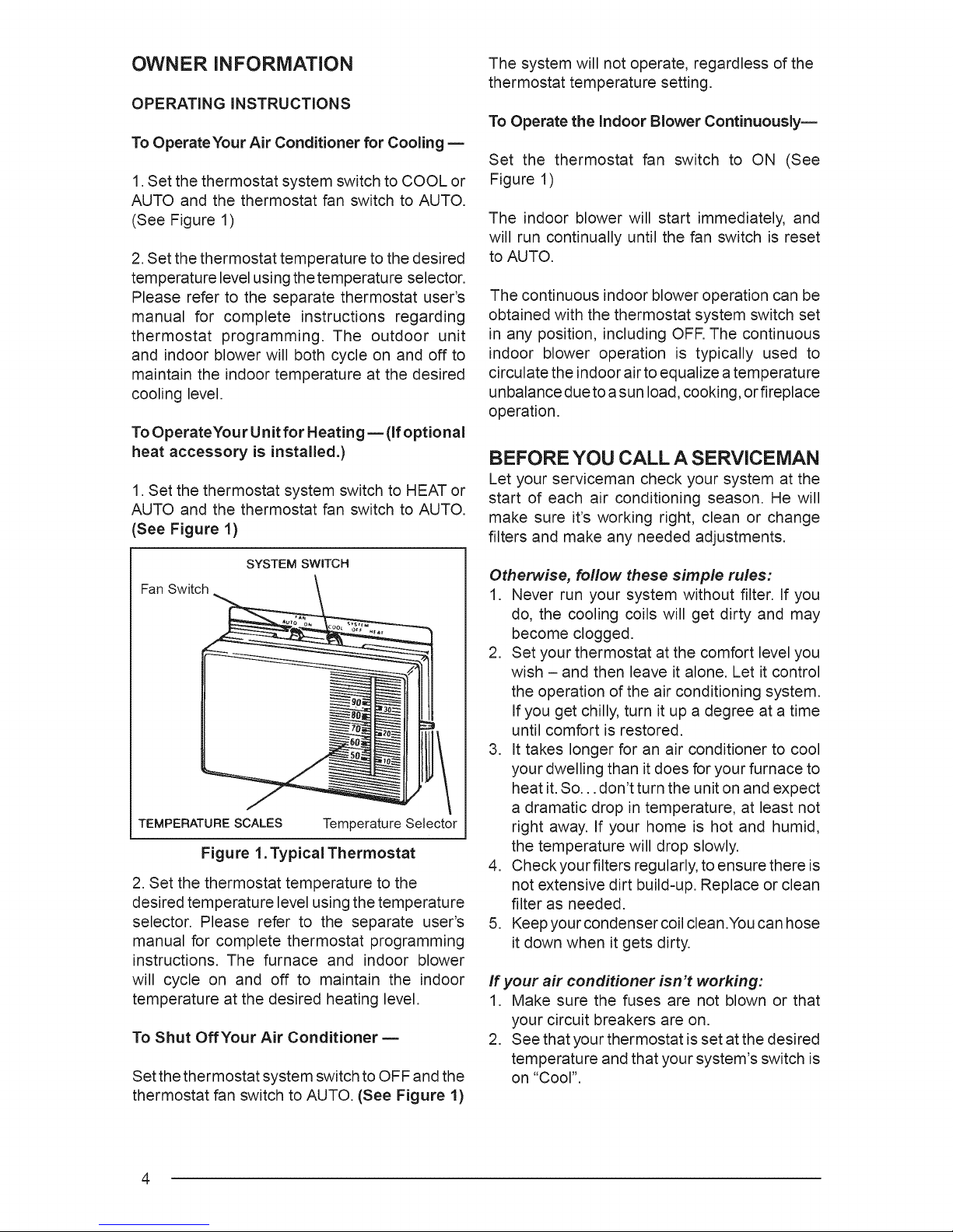
SYSTEM SWITCH
Fan Switch
TEMPERATURE SCALES Temperature Selector
Figure 1. Typical Thermostat
2. Set the thermostat temperature to the
desired temperature level using the temperature
selector. Please refer to the separate user's
manual for complete thermostat programming
instructions. The furnace and indoor blower
will cycle on and off to maintain the indoor
temperature at the desired heating level.
To Shut OffYour Air Conditioner m
Set the thermostat system switch to OFF and the
thermostat fan switch to AUTO. (See Figure 1)
The system will not operate, regardless of the
thermostat temperature setting.
To Operate the Indoor Blower Continuously==
Set the thermostat fan switch to ON (See
Figure 1)
The indoor blower will start immediately, and
will run continually until the fan switch is reset
to AUTO.
The continuous indoor blower operation can be
obtained with the thermostat system switch set
in any position, including OFR The continuous
indoor blower operation is typically used to
circulate the indoor air to equalize a temperature
unbalance due to asun load, cooking, or fireplace
operation.
BEFORE YOU CALL A SERVICEMAN
Let your serviceman check your system at the
start of each air conditioning season. He will
make sure it's working right, clean or change
filters and make any needed adjustments.
Otherwise, foflow these simple rules:
1. Never run your system without filter. If you
do, the cooling coils will get dirty and may
become clogged.
2. Set your thermostat at the comfort level you
wish - and then leave it alone. Let it control
the operation of the air conditioning system.
If you get chilly, turn it up a degree at a time
until comfort is restored.
3. It takes longer for an air conditioner to cool
your dwelling than it does for your furnace to
heat it. So... don't turn the unit on and expect
a dramatic drop in temperature, at least not
right away. If your home is hot and humid,
the temperature will drop slowly.
4. Checkyour filters regularly, to ensure there is
not extensive dirt build-up. Replace or clean
filter as needed.
5. Keep your condenser coil clean .Youcan hose
it down when it gets dirty.
If your air conditioner isn't working:
1. Make sure the fuses are not blown or that
your circuit breakers are on.
2. See that your thermostat is set at the desired
temperature and that your system's switch is
on "Cool".
3. For free air flow,makesureyour return
registerisnotcoveredandthatthefilteris
clean.
4. Checkthecondensercoilandmakesureitis
cleanandnotcloggedwithgrassorleaves.
Ifyourairconditionerstillisn'tworking,callyour
nearestcontractor.
SPECIFICATIONS
Packaged Air Conditioners are designed for
outdoor rooftop or ground level slab installations.
The units are shipped ready for horizontal
duct connections and are easily converted for
downflow applications.
WARNING:
Improper installation, service,
adjustment, or maintenance may
cause explosion, fire, electrical shock
or other hazardous conditions which
may result in personal injury or
property damage. Unless otherwise
noted in these instructions, only
factory authorized kits or accessories
may be used with this product.
Noncompliance may void the unit's
warranty.
All models are shipped from the factory with
the following:
1. Zero clearance to combustibles.
2. Multi-speed direct-drive or fixed torque
blower.
3. High Pressure Switch.
4. Blower Speed Relay.
5. Horizontal or Downflow duct connections.
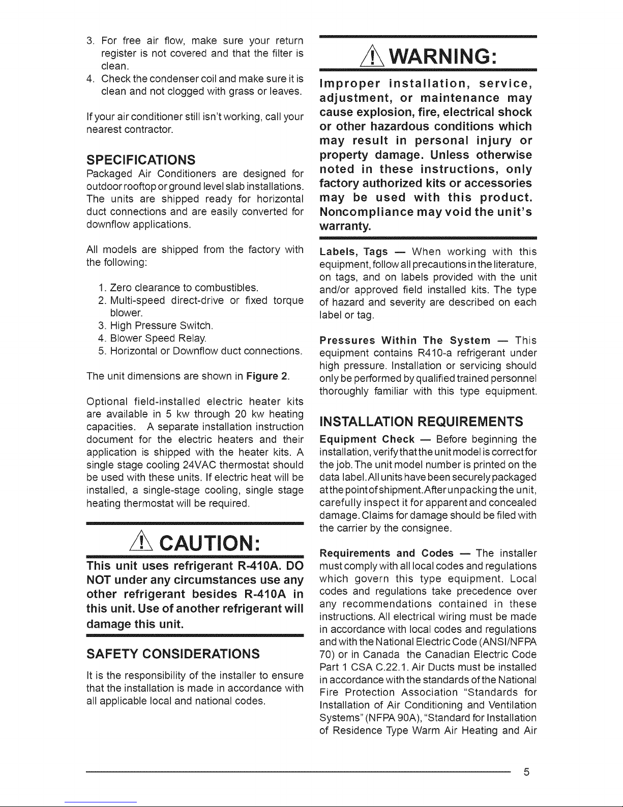
The unit dimensions are shown in Figure 2.
Optional field-installed electric heater kits
are available in 5 kw through 20 kw heating
capacities. A separate installation instruction
document for the electric heaters and their
application is shipped with the heater kits. A
single stage cooling 24VAC thermostat should
be used with these units. If electric heat will be
installed, a single-stage cooling, single stage
heating thermostat will be required.
CAUTION:
This unit uses refrigerant R=410A. DO
NOT under any circumstances use any
other refrigerant besides R=410A in
this unit. Use of another refrigerant will
damage this unit.
SAFETY CONSIDERATIONS
It is the responsibility of the installer to ensure
that the installation is made in accordance with
all applicable local and national codes.
Labels, Tags m When working with this
equipment, follow all precautions inthe literature,
on tags, and on labels provided with the unit
and/or approved field installed kits. The type
of hazard and severity are described on each
label or tag.
Pressures Within The System m This
equipment contains R410-a refrigerant under
high pressure. Installation or servicing should
only be performed by qualified trained personnel
thoroughly familiar with this type equipment.
INSTALLATION REQUIREMENTS
Equipment Check = Before beginning the
installation, verify that the unit model is correct for
the job. The unit model number is printed on the
data label.All units have been securely packaged
atthe point of shipment.After unpacking the unit,
carefully inspect it for apparent and concealed
damage. Claims for damage should be filed with
the carrier by the consignee.
Requirements and Codes _ The installer
must complywith all local codes and regulations
which govern this type equipment. Local
codes and regulations take precedence over
any recommendations contained in these
instructions. All electrical wiring must be made
in accordance with local codes and regulations
and with the National Electric Code (ANSI/NFPA
70) or in Canada the Canadian Electric Code
Part 1 CSA C.22.1. Air Ducts must be installed
in accordance with the standards of the National
Fire Protection Association "Standards for
Installation of Air Conditioning and Ventilation
Systems" (NFPA 90A), "Standard for Installation
of Residence Type Warm Air Heating and Air
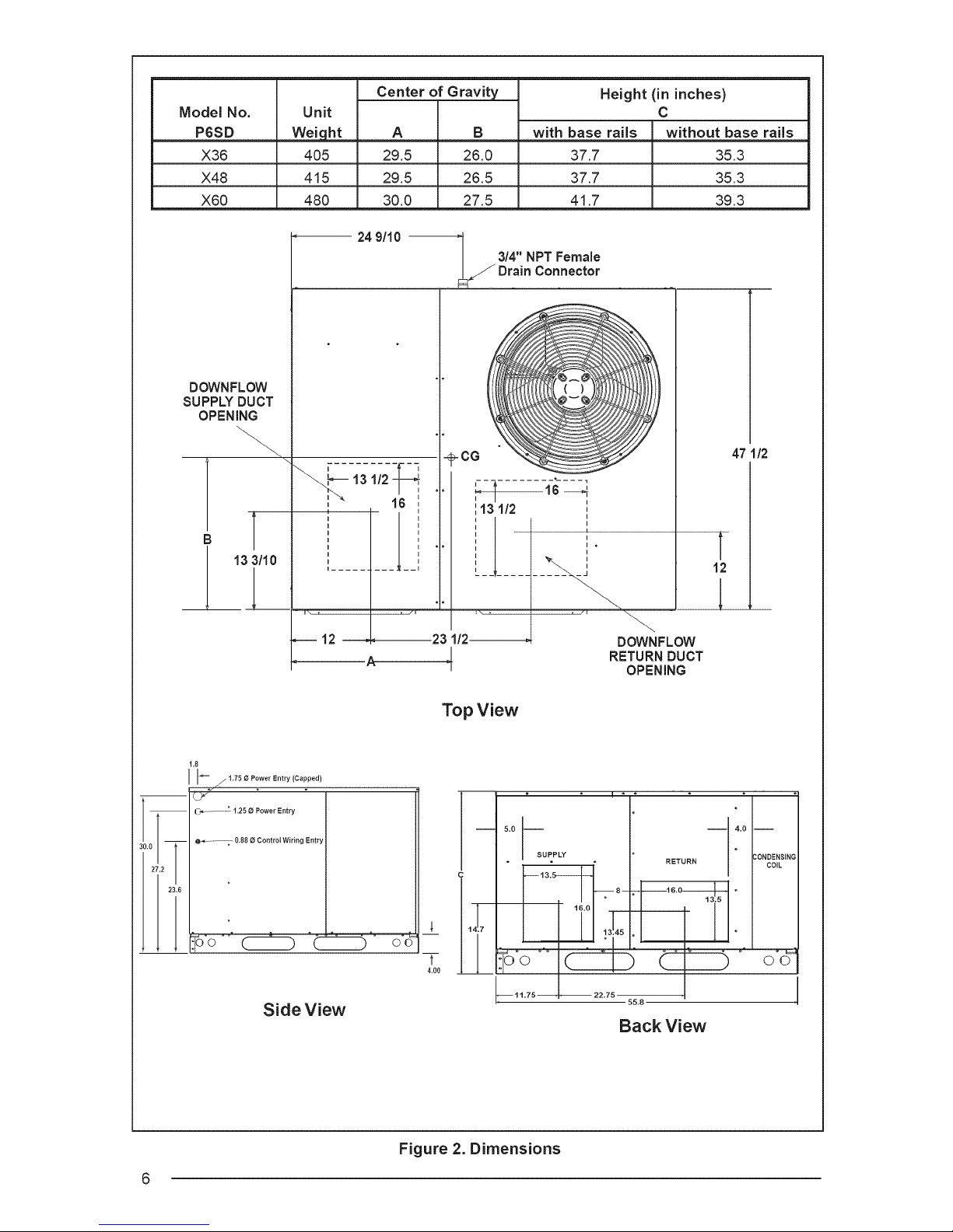
Model No.
P6SD
X36
X48
X60
DOWNFLOW
SUPPLY DUCT
OPENING
Unit
Weiqht
4O5
415
48O
Center of Gravity
A
29.5
29.5
30.0
24 9/10 _ 3/4" NPT Female
_ Drain Connector
B
26.0
26.5
27.5
with base rails
37.7
37.7
41.7
Height (in inches)
C
without base rails
35.3
35.3
39.3
1.8
i i
I I- z _.7_oPowerEntry (Capped)
m
t-_- "--'° 1.25 0 Power Entry
@_---; 0.88 0 ControIWiring Entry
0.0_-
27.2 I
I I
I 23.6
L._ 13 1/2 '
n i
............ i
_ml\ , , /i
16 ',
1=
A
_-CG
113112 I
,[ '
i\ , , _1
23 1/2
4
Top View
I m
..................... i
5,0 --
SUPPLY
DOWNFLOW
RETURN DUCT
16.0
OPENING
-- 4.0 --
RETURN COIL
_ _16"0--_13. 5 _
47 1/2
30NDEN$1NG
Side View
6
4.00
©o© o_o
--11.75_
Figure 2. Dimensions
22.75
Back View
 Loading...