

Nordyne Q5RD, Q5RD024K, Q5RD030K, Q5RD036K, Q5RD042K Installation Manual
...
Q5RD SERIES
13 SEER
USER’s MANUAL & INSTALLATION INSTRUCTIONS
Single Package Heat Pump - Single Stage, R-410A
Please read this information thoroughly and become familiar with the capabilities
and use of your appliance before attempting to operate or maintain this unit.
Keep this literature where you have easy access to it in the future. If a problem
occurs, check the instructions and follow recommendations given. If these
suggestions don’t eliminate your problem, call your servicing contractor.
These instructions are primarily intended to assist qualifi ed individuals
experienced in the proper installation of this appliance. Some local codes
require licensed installation/service personnel for this type of equipment.
Read all instructions carefully before starting the installation.
DO NOT DESTROY. PLEASE READ CAREFULLY AND
KEEP IN A SAFE PLACE FOR FUTURE REFERENCE.
IMPORTANT

USER INFORMATION
About the Heat Pump ................................... 3
Operating Instructions ................................ 3
Cooling Operation .................................... 3
Heating Operation ....................................3
Emergency Heat ......................................3
Defrost .....................................................3
System Shutdown .................................... 3
INSTALLER INFORMATION
Important Safety Information ......................4
General Information .....................................4
Before You Install this Unit ..........................4
Locating the Heat pump ............................ 4
Minimum Clearances .................................5
Service Access Clearance ......................5
Clearances to Combustibles ...................5
Air Duct System .........................................5
Heat Pump Installation .................................5
Unpacking the Unit ....................................5
Installing Return & Supply Air Collars ........5
Supply Duct ............................................5
Return Duct .............................................6
Connecting Return & Supply Air
Flexible Ducts .............................................6
Locating & Installing the Return Air
Assembly .................................................... 6
Locating & Installing the Supply
Dampers ..................................................... 7
Condensate Drainage .................................7
Electrical Connections .................................8
Pre - Electrical Checklist.............................8
Line Voltage ................................................8
Overcurrent Protection ............................... 9
Blower Speed ............................................9
2 - Speed Outdoor Fan Motor ..................9
Defrost Cycle Control .................................9
Ambient Sensor Mounting 10
Thermostat Connections ..........................10
Electric Heat Package ..............................11
Grounding .................................................11
Startup & Adjustments...............................11
Pre - Start Checklist .................................11
Start - Up Procedure ................................11
Air Circulation ........................................11
System Heating .....................................11
System Cooling ......................................11
IMPORTANT SAFETY INFORMATION
Safety markings are used frequently throughout
this manual to designate a degree or level
of seriousness and should not be ignored.
WARNING indicates a potentially hazardous
situation that if not avoided, could result in
personal injury or death. CAUTION indicates
a potentially hazardous situation that if not
avoided, may result in minor or moderate injury
or property damage.
Short Cycle Protection ...........................12
Emergency Heat ....................................12
Defrost Test Procedure .............................12
Anti Short Cycle Timer Test ......................12
Heating Mode ........................................12
Cooling Mode .........................................12
Adjustment of Refrigerant Charge ............12
Charging an R-410A Unit in AC Mode
with Outdoor Temp above 65° F ...............12
Charging R-410A Unit in Heat Mode .......13
Component Functions ...............................13
Low Pressure Switch ................................13
High Pressure Switch ...............................13
Unit Maintenance ........................................13
Figures & Tables .........................................13
Figure 9. - Unit Dimensions ....................13
Table 4. - Q5RD Physical Data ...............13
Charging Tables - Cooling Mode ..............14
Table 5. - Q5RD-X24K (2 Ton Units) .......14
Table 6. - Q5RD-X30K (2.5 Ton Units) ....14
Table 7. - Q5RD-X36K (3 Ton Units) .......15
Table 8. - Q5RD-X42K (3.5 Ton Units) ....15
Table 9. - Q5RD-X48K (4 Ton Units) .......16
Table 10. - Q5RD-X60K (5 Ton Units) .....16
Charging Tables - Heating Mode ..............17
Table 11. - Q5RD-X24K (2 Ton Units) .....17
Table 12. - Q5RD-X30K (2.5 Ton Units) ..17
Table 13. - Q5RD-X36K (3 Ton Units) .....18
Table 14. - Q5RD-X42K (3.5 Ton Units) ..18
Table 15. - Q5RD-X48K (4 Ton Units) .....19
Table 16. - Q5RD-X60K (5 Ton Units) .....19
Wiring Diagrams .......................................20
Figure 10. - 2 & 2.5 Ton Units .................20
Figure 11. - 3,4, & 5 Ton Units ................21
Figure 12. - Thermostat Connections .....22
Installation / Performance Checklist .........24
2

USER INFORMATION
ABOUT THE HEAT PUMP
Your heat pump is a unique, all weather comfortcontrol appliance that will heat and cool your
home year round and provide energy saving
comfort. It’s an unknown fact that heat is always
in the air, even when the outside temperature is
below freezing. The heat pump uses this basic
law of physics to provide energy saving heat
during the winter months. For example, If the
outdoor temperature is 47° F (8° C), your heat
pump can deliver approximately 3.5 units of
heat energy per each unit of electrical energy
used, as compared to a maximum of only 1
unit of heat energy produced with conventional
heating systems.
In colder temperatures, the heat pump performs
like an air conditioner run in reverse. Available
heat energy outside the home is absorbed by
the refrigerant and exhausted inside the home.
This effi cient process means you only pay for
“moving” the heat from the outdoors to the indoor
area. You do not pay to generate the heat, as is
the case with more traditional furnace designs.
During summer, the heat pump reverses the fl ow
of the heat-absorbing refrigerant to become an
energy-effi cient, central air conditioner. Excess
heat energy inside the home is absorbed by the
refrigerant and exhausted outside the home.
Operating Instructions
Cooling Operation
1. Set the thermostat’s system mode to COOL
or AUTO and change the fan mode to AUTO.
See Figure 1.
2. Set the temperature selector to the
desired temperature level. The outdoor fan,
compressor, and blower motor will all cycle
on and off to maintain the indoor temperature
at the desired cooling level.
minutes following a previous operation or the
interruption of the main electrical power.
Emergency Heat
Some thermostats may include a system mode
called EM HT or AUX HT, etc. This is a backup heating mode that should only be used if a
problem is suspected. With the mode set to EM
HT, etc., the compressor and outdoor fan will
be locked off and supplemental heat (electric
resistance heating) will be used as a source
of heat (if installed). Sustained use of electric
resistance heat in place of the heat pump will
result in an increase in electric utility costs.
Defrost
During cold weather heating operation, the
outdoor unit will develop a coating of snow
and ice on the heat transfer coil. This is normal
and the unit will defrost itself. This unit features
Demand Defrost that monitors ambient and coil
temperatures to regulate the defrost function
accordingly.
At the beginning of the defrost cycle, both the
outdoor condenser fan and compressor will
turn off. After approximately 30 seconds, the
compressor will turn on and begin to heat the
outdoor coil causing the ice and snow to melt.
NOTE: While the ice and snow is melting, steam
may rise from the outdoor unit as the warm coil
causes the melting frost to evaporate. When
defrost is completed, the outdoor fan motor will
start, and the compressor will turn off again. In
approximately 30 seconds the compressor will
start up again and continue normal operation.
System Shutdown
Change the thermostat’s system mode to OFF
and the fan mode to AUTO (See Figure 1).
NOTE: The system will not operate, regardless
of the temperature selector setting.
Heating Operation
1. Set the thermostat’s system mode to HEAT
or AUTO and change the fan mode to AUTO.
See Figure 1.
2. Set the temperature selector to the desired
temperature level. The compressor, outdoor
fan, and blower motor will cycle on and off to
maintain the indoor temperature at the desired
heating level.
NOTE: If the temperature level is re-adjusted, or
the system mode is reset, the fan and compressor
in the outdoor unit may not start immediately. A
protective timer circuit holds the compressor
and the outdoor fan off for approximately three
Fan
Mode
Figure 1. Digital Thermostat
System
Mode
Temperature
Selector
3

INSTALLER INFORMATION
IMPORTANT SAFETY INFORMATION
WARNING:
The information listed below
must be followed during the
installation, service, and operation
of this unit. Unqualifi ed individuals
should not attempt to interpret
these instructions or install this
equipment. Failure to follow safety
recommendations could result in
possible damage to the equipment,
serious personal injury or de
• The installer must comply with all local
codes and regulations which govern the
installation of this type of equipment. Local
codes and regulations take precedence over
any recommendations contained in these
instructions. Consult local building codes
and the National Electrical Code (ANSI CI)
for special installation requirements.
• This equipment contains liquid and gaseous
refrigerant under high pressure. Installation or
servicing should only be performed by qualifi ed
trained personnel thoroughly familiar with this
type equipment.
• All electrical wiring must be completed in
accordance with local, state and national
codes and regulations and with the National
Electric Code (ANSI/NFPA 70) or in Canada
the Canadian Electric Code Part 1 CSA C22.1.
• Follow all precautions in the literature, on tags,
and on labels provided with the equipment.
Read and thoroughly understand the
instructions provided with the equipment prior
to performing the installation and operational
checkout of the equipment.
GENERAL INFORMATION
Single packaged heat pumps are ready for easy
and immediate installation and can be readily
connected into the high static duct system of a
home. This unit is completely assembled, wired,
and run tested at the factory. This heat pump
is designed for outdoor installation only. The
only connections needed for installation are the
supply and return ducts, the line voltage, and
thermostat wiring. Use of components other than
those specifi ed may invalidate ARI Certifi cation,
Code Agency Listing, and limited warranty on
the air conditioner.
4
ath
Before You Install this Unit
The cooling load of the area to be conditioned
must be calculated and a system of the proper
capacity selected. It is recommended that the
area to be conditioned be completely insulated
and vapor sealed.
Check the electrical supply and verify the
power supply is adequate for unit operation.
If there is any question concerning the power
supply, contact the local power company.
All units are securely packed at the time of
shipment and upon arrival should be carefully
inspected for damage prior to installing the
equipment at the job site. Verify coil fi ns are
straight. If necessary, comb fi ns to remove
.
fl attened or bent fi ns. Claims for damage
should be fi led immediately with the carrier.
Please consult your dealer for maintenance
information and availability of maintenance
contracts. Please read all instructions before
installing the unit.
Locating the Heat Pump
• Survey the job site to determine the best
location for mounting the outdoor unit. Select
a solid, level position, preferably on a concrete
slab, slightly above the grade level, and parallel
to the home. If possible, select a site for the unit
that is as close as possible to the proposed
return grille location. DO NOT PLACE UNIT
UNDER THE HOME.
• The unit should be located with consideration of
minimizing the length of the supply and return
ducts. If practical, place the heat pump and
its ducts in an area where they will be shaded
from the afternoon sun, when the heat load is
greatest.
• The length of the supply and return ducts
should be kept to a minimum with no sharp
radius bends.
• Overhead obstructions, poorly ventilated
areas, and areas subject to accumulation of
debris should be avoided. The hot condenser
air must be discharged up and away from the
home, and if possible, in a direction with the
prevailing wind. Do not place the unit in a
confi ned space. See Figure 9 & Table 4 (page
13) for unit dimensions.
• Suffi cient clearance for unobstructed airfl ow
through the outdoor coil must be maintained
in order to achieve rated performance. See
Figure 2 (page 5) for minimum clearances to
obstructions.
• Consideration should also be given to
availability of electric power, service access,
noise, and shade.

Minimum Clearances
Minimum clearances MUST be maintained from
adjacent structures to provide room for proper
servicing and air circulation. DO NOT install unit
in a confi ned or recessed area that will allow
discharge air from the unit to re-circulate into the
condenser air inlet, through the coil. See Figure 2.
Service Access Clearance:
Blower access panel side ...........................24”
Electrical compartment access panel side .. . 1 2”
Clearance between overhang and top
of unit ..................................................... 72”
Clearance around condenser coil area to
wall or shrubs (excludes duct panel side) ...12”
Clearances to Combustibles:
Combustible base - wood or Class A, B, or C
roof covering material ................................. 0”
Supply & return air ducts ............................. 0”
Duct connection side ................................... 0”
• For highly resistive duct systems it may be
necessary to add an additional return air
duct and or supply to achieve maximum
performance and prevent coil icing and
refrigerant fl ood back.
• The heat pump system will not cool or
heat the home if air is lost to the outside
through leaks in the duct system. Ducts
that are collapsed or restricted by foreign
objects will also prevent adequate air fl ow.
• All duct work passing through unconditioned
space must be properly insulated to minimize
duct losses and prevent condensation.
Use insulation with an outer vapor barrier.
Refer to local codes for insulation material
requirements.
HEAT PUMP INSTALLATION
Unpacking the Unit
It is recommended that the unit be unpacked
at the installation site to minimize damage due
to handling.
12"
24"
TO BE
TOP OF UNIT
UNOBSTRUCTED
0"
Figure 2. Minimum Unit Clearances
Air Duct System
Air ducts should be installed in accordance with
the standards of the National Fire Protection
Association “Standard for Installation of Air
Conditioning and Ventilation Systems” (NFPA
90A), “Standard for Installation of Residence
Type Warm Air Heating and Air Conditioning
Systems” (NFPA 90B), these instructions, and all
applicable codes. NFPA publications are available
by writing to: National Fire Protection Association,
Batterymarch Park, Quincy, ME 02269 or visit
www.NFPA.org on the web.
• Design the duct work according to methods
described by the Air Conditioning Contractors
of America (ACCA).
• The supply duct system, including the number
and type of registers, will have much more
effect on the performance of the system than
any other factor. The duct must be suffi ciently
large to conduct an adequate amount of air to
each register. See Figure 5 (page 7).
• Duct work should be attached directly to the
unit fl anges for horizontal applications.
12"
CAUTION:
Do not tip the unit on its side.
Oil may enter the compressor
cylinders and cause starting
trouble. If unit has been set on its
side, restore to upright position
and do not run for several hours.
Then run unit for a few seconds.
Do this three or four times with fi ve
minutes between runs.
1. Remove the bands from around the unit.
2. Unfold the top and bottom cap fl anges.
3. Carefully remove the top cap and tube.
Installing Return & Supply Air Collars
If the supply and return collars are supplied
with the unit, they will be located in the supply
duct. They can be easily positioned over the unit
openings (Figure 3, page 6) and secured with
sheet metal screws.
• The diameter of the return duct collar is 14”.
NOTE: 2 ton units are designed with 12” returns.
• The diameter of the supply duct collar is 12”.
• Before permanently installing the collars,
it is recommended you pre-fi t them over
the openings fi rst to determine best fi t and
alignment.
Supply Duct
1. Assemble the collar by overlapping the two ends.
NOTE: One end of the collar is slotted and
the opposite end has two small holes. Position
the end with small screw holes underneath
the slotted end.
5
2. Fasten the collar ends with two self drilling
sheet metal screws.
3. Position the collar over the opening and align
the 4 holes in the collar with the 4 holes (or
dimples depending on model) in the rear panel.
4. Using self-drilling screws (10-16x.5), secure
the collar to the rear panel.
Return Duct
1. Assemble the collar by overlapping the two ends.
NOTE: One end of the collar is slotted and
the opposite end has two small holes. Position
the end with small screw holes underneath
the slotted end.
2. Fasten the collar ends with two self drilling
sheet metal screws.
3. Position the collar over the opening. Align the
four holes in the collar with the four dimples or
holes (depending on unit model) in the panel.
4. Secure the collar to the rear panel using self
drilling screws (10-16x.5).
Duct
Transition
Duct Screws
Supply Air
Dimples
Return Air
Figure 3. Return & Supply Air Collars
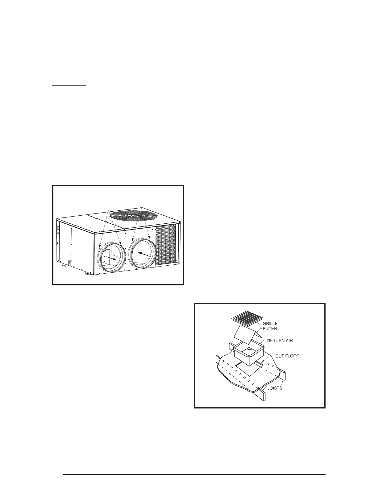
Locating & Installing the Return Air Assembly
To simplify installation, locate and install the
return air assembly fi rst. If desired, the return
opening can be located inside a closet with
louvered doors that has an open area equal to
or greater than a 12” x 20” grille. The return air
grille can be placed in the wall of a closet and
the ducted into the fi lter box through a boxed-in
area at the closet fl oor level. Make sure the fi lter
is readily accessible.
NOTE: The return air box with grille and fi lter
(Figure 4) should not be located in heavy traffi c
areas like hallways or center of rooms. A good
spot is in a corner or under a table, if a minimum
two inch clearance is available.
1. Start the installation from under the home by
cutting a small hole in the sub-fl oor. Determine
how the fl oor joist location will affect cutting
the opening needed for the return air box.
NOTE: Floor joists are generally located on
16” centers, leaving 14-3/8” between joists.
2. After measuring the return air box
(approximately 12-1/4” x 20-1/4”), cut the
hole through the fl oor so that the box will fi t
between the fl oor joists. Care should be taken
when cutting through carpeting to avoid snags.
NOTE: In most installations it will be necessary
to cut a similar hole in the fi berboard directly
under the hole in the fl oor. However, if the fl oor
is more than ten inches deep, it will only be
necessary to cut a hole for the collar on the
return air box or for the insulated duct.
3. Set the box into the opening and fasten with
screws or nails.
4. Put the fi lter and return air grille in place.
Connecting Return & Supply Air Flexible
Ducts
• Flexible ducts may be cut to the required
length and spliced with sheet metal sleeves
and clamps. Keep all ducts as short and
straight as possible. Avoid sharp bends.
Please follow all instructions packed with duct.
• Flexible ducts can be secured to the
corresponding collars with the provided
clamps. After the inner duct is connected to
the collar, pull the insulation and plastic sleeve
over the connection and clamp. NOTE: To
prevent a loss in cooling capacity, make sure
all connections are tight.
• Homes with multiple supply ducts (or special
applications), a Y fi tting is available for dividing
the supply air to different areas of the home for
more effi cient cooling. NOTE: For maximum
performance, insulate the Y fi tting.
6
Figure 4. Return Air Box

MULTIPLE DUCT APPLICATIONSINGLE DUCT APPLICATION
Figure 5. Typical Duct Applications
Locating & Installing the Supply Damper(s)
When locating the supply damper(s), carefully
check fl oor joists and frame members that could
interfere with the installation of the damper or
fl exible duct. Ideally, the damper (Figure 6) should
be located in the bottom of the main duct, forward
of center of the home, at least three feet from
the nearest register. The round supply opening
in the slanted side of the damper should face the
side of the home where the heat pump is located.
1. Locate the center of the heat duct by cutting
a small hole in the fi berboard below the duct
at the desired location.
2. Cut a hole approximately 3/4” larger than the
damper opening in the fi berboard.
3. Cut a 9-1/8” x 13-1/8” hole in the duct and
bend over all tabs fl at on the inside of the
heat duct.
4. Insert the damper into the duct and bend over
all tabs fl at on the inside of the heat duct.
5. Seal the opening between the fi berboard and
damper or fl exible duct.
Condensate Drainage
A 3/4” condensate fi tting extends out of the side
of the unit as shown in Figure 7. The drain trap,
shipped in the electrical compartment, must be
installed to prevent water from collecting inside
the unit.
1. Thread the elbow provided with the unit into
the drain connection until hand tight.
2. Connect the condensate tubing onto the fi tting,
forming a trap near the drain connection. See
Figure 7.
3. Route the condensate tube from the trap to
a suitable drain. NOTE: For proper drainage,
make sure the trap is level to the ground and
tubing outlet is below trap level.
Elbow
AUTOMATIC DAMPER IS CLOSED
Figure 6. Supply Damper
WHEN HEAT PUMP IS OFF
P-Trap
Figure 7. Drain Trap
7

ELECTRICAL CONNECTIONS
WARNING:
To avoid electric shock, personal
injury, or death, turn off the electric
power at the disconnect or the main
service panel before making any
electrical connections.
• Electrical connections must be in
compliance with all applicable local codes
and ordinances, and with the current
revision of the National Electric Code
(ANSI/NFPA 70).
• For Canadian installations the electrical
connections and grounding shall comply with
the current Canadian Electrical Code (CSA
C22.1 and/or local codes).
Pre-Electrical Checklist:
Verify that the voltage, frequency, and phase
of the supply source match the specifi cations
on the unit rating plate.
Verify that the service provided by the utility is
suffi cient to handle the additional load imposed
by this equipment. Refer to the unit wiring label
for proper high and low voltage wiring.
Verify factory wiring is in accordance with the
unit wiring diagram (Figures 10 & 11, pages
20 & 21). Inspect for loose connections.
Line Voltage
• It is recommended that the line voltage to the
unit be supplied from a dedicated branch circuit
containing the correct fuse or circuit breaker
for the unit.
• An electrical disconnect must be located
within sight of and readily accessible to the
unit. This switch shall be capable of electrically
de-energizing the outdoor unit. See unit data
label for proper incoming fi eld wiring. Any
other wiring methods must be acceptable to
authority having jurisdiction.
• Provide power supply for the unit in accordance
with the unit wiring diagram, and the unit rating
plate.
• Connect the line-voltage leads to the
terminals on the contactor inside the control
compartment. Extend leads through power
wiring hole (Figure 8). Connect L1 & L2 directly
to the contactor.
• Use only copper wire for the line voltage
power supply to this unit as listed in Table 1.
Use proper code agency listed conduit and a
conduit connector for connecting the supply
wires to the unit. Use of rain tight conduit is
recommended.
8
• See the unit wiring label for proper high and low
voltage wiring. Make all electrical connections
in accordance with all applicable codes and
ordinances. See Figures 10 & 11 (pages 20
& 21)
CAUTION:
Label all wires prior to
disconnection when servicing
controls. Wiring errors can
cause improper and dangerous
operation. Verify proper operation
after servicing.
• Units are shipped from the factory wired for 240
volt transfor mer operation. For 208V operation,
remove the lead from the transformer ter minal
marked 240V and connect it to the terminal
marked 208V.
COPPER WIRE SIZE — AWG
(1% Voltage Drop)
Supply Wire
Length (Feet)
200 150 100 50
6 8 10 14 15
46812 20
46810 25
44610 30
346 8 35
346 8 40
234 6 45
234 6 50
234 6 55
123 4 60
Wire Size based on N.E.C. for 60° type
copper conductors.
Table 1. Copper Wire Size
High Voltage
Low Voltage
Figure 8. Power Entry
Supply
Circuit
Ampacity
 Loading...