

Nordyne O4HD-091A-14-FA-DV, O4HD-091A-12-FB, O4HD-091A-V-FA Maintenance Manual
Installation, Operation and
Maintenance Manual
Oil Fired Warm Air Furnaces
O4HD-091A-12-FB (Up-Flow Model)
O4HD-091A-14-FA-DV (Up-Flow Model)
O4HD-091A-V-FA (Up-Flow Model with ECM)
FOR YOUR SAFETY:
Do not store or use gasoline or other flammable liquids or
vapors in the vicinity of this, or any other appliance.
ALL INSTALLATIONS MUST MEET ALL
LOCAL, PROVINCIAL/STATE, AND
FEDERAL CODES WHICH MAY
DIFFER FROM THIS MANUAL
NORDYN E INC.
Read this complete manual before
beginning installation. These instructions
must be kept with the furnace for future
reference.
®
C
151B-0810 (Replaces 151B-0909)

TABLE OF CONTENTS
1. INTRODUCTION ................................................................................................................................. 3
2. HEAT LOSS ........................................................................................................................................ 3
3. LOCATION OF UNIT .......................................................................................................................... 3
4. AIR CONDITIONING APPLICATIONS ............................................................................................... 4
5. COMBUSTION AIR ............................................................................................................................. 4
6. CHIMNEY VENTING ........................................................................................................................... 4
7. BAROMETRIC DAMPER CONTROL ................................................................................................. 4
8. OPTIONAL SIDE WALL VENTING ..................................................................................................... 5
9a, 9b. FAN TIMER BOARD AND LIMIT CONTROL (FIGURE 4 AND 5) ............................................. 5
10. ELECTRICAL CONNECTIONS ......................................................................................................... 5
11. HUMIDIFIER ...................................................................................................................................... 6
12. PIPING INSTALLATION ................................................................................................................... 6
13. OIL FILTER ....................................................................................................................................... 6
14. OIL BURNER NOZZLES ................................................................................................................... 6
15. OIL BURNER ADJUSTMENT ........................................................................................................... 6
16. BURNER ELECTRODES .................................................................................................................. 7
17. BURNER PRIMARY (SAFETY) CONTROL ...................................................................................... 7
18. COMBUSTION CHAMBER ............................................................................................................... 7
19a, 19b. CIRCULATING AIR BLOWER ................................................................................................ 7
20. MAINTENANCE AND SERVICE ....................................................................................................... 8
21. OPERATING INSTRUCTIONS .......................................................................................................... 9
22. ECM BLOWER MOTOR OPERATION ...................................................................................... 9
APPENDIX A- O4HD-091A-12-FB, O4HD-091A-14-FA-DV AND O4HD-091A-V-FA ........................... 11
A.1 OIL BURNER AIR ADJUSTMENT .................................................................................................. 12
A.2 BURNER ELECTRODES ................................................................................................................ 12
A.3 START UP ....................................................................................................................................... 12
APPENDIX B: WIRING DIAGRAMS ...................................................................................................... 17
OPERATION OF OIL BURNER ............................................................................................................. 19
APPENDIX C OIL PRIMARY CONTROL DETAILED SEQUENCE OF OPERATION ......................... 20
OIL PRIMARY CONTROL LED DIAGNOSTIC LIGHT .......................................................................... 24
FINAL CHECK OUT ............................................................................................................................... 30
HOMEOWNER'S REFERENCE TABLE ................................................................................................ 31
PARTS LISTING: HIGHBOY MODEL: O4HD-091A-12-FB, O4HD-091A-14-FA-DV, AND
O4HD-091A-V-FA .................................................................................................................................. 32
NOTES: .................................................................................................................................................................. 35
IMPORTANT:
SAVE THESE INSTRUCTIONS FOR FUTURE REFERENCE
1. INTRODUCTION 3. LOCATION OF UNIT
Please read these instructions completely and carefully
before installing and operating the furnace.
MODELS O4HD-091A-12-FB, O4HD-091A-14-FA-
DV, AND O4HD-091A-V-FA
Models O4HD-091A-12-FB, O4HD-091A-14-FA-DV and
O4HD-091A-V-FA are oil fired forced air up-flow furnaces
with an output capacity range of 59,000 BTU/Hr. to
86,000 BTU/Hr.
I `cAUTION I
DO NOT USE GASOLINE, CRANK CASE OIL, OR
ANY OIL CONTAINING GASOLINE.
All models are CSA listed, (NRTL/C) for use with No. 1
(Stove) and No. 2 (Furnace) Oil. Please refer to the
tables in Appendix A for performance and dimensional
data.
In Canada, the installation of the furnace and related
equipment shall be installed in accordance with the
regulations of CAN/CSA - B139, Installation Code for Oil-
Buming Equipment, as well as in accordance with local
codes.
In the United States of America, the installation of the
furnace and related equipment shall be installed in
accordance with the regulations of NFPA No. 31,
Standard for the Installation of OiI-Buminq Equipment, as
well as in accordance with local codes.
Regulations prescribed in the National Codes and Local
regulations take precedence over the general
instructions provided on this installation manual. When in
doubt, please consult your local authorities.
All models are shipped assembled and pre-wired. The
furnace should be carefully inspected for damage when
being unpacked.
The furnace should be located such that the flue
connection to the chimney is short, direct and
consists of as few elbows as possible. When
possible, the unit should be centralized with respect
to the supply and return air ductwork. A central
location minimizes the trunk duct sizing. All models
may be installed on combustible floors.
The minimum installation clearances are listed in
Table 1.
Table 1: Clearances - (Inches)
Clearance to Combustibles
O4HD-091A-12-FB, O4HD-
Location
Top
Bottom
S/A Plenum
Rear
Sides
Front
Flue Pipe
Enclosure
"18 in. in USA
** 24 in. required for service clearance
091A-14-FA-DV and O4HD-
091A-V-FA
Up flow
1
0
1
1
1
1 **
9*
Closet
2. HEAT LOSS
The maximum hourly heat loss for each heated space
shall be calculated in accordance with the procedures
described in the manuals of the Heating, Refrigeration
and Air Conditioning Institute of Canada (HRAI), or by
other means prescribed, or approved by the local
authority having jurisdiction.
In the United States, Manual J. titled, "Load Calculation"
published by the Air Conditioning Contractors of
America, describes a suitable procedure for calculating
the maximum hourly heat loss.
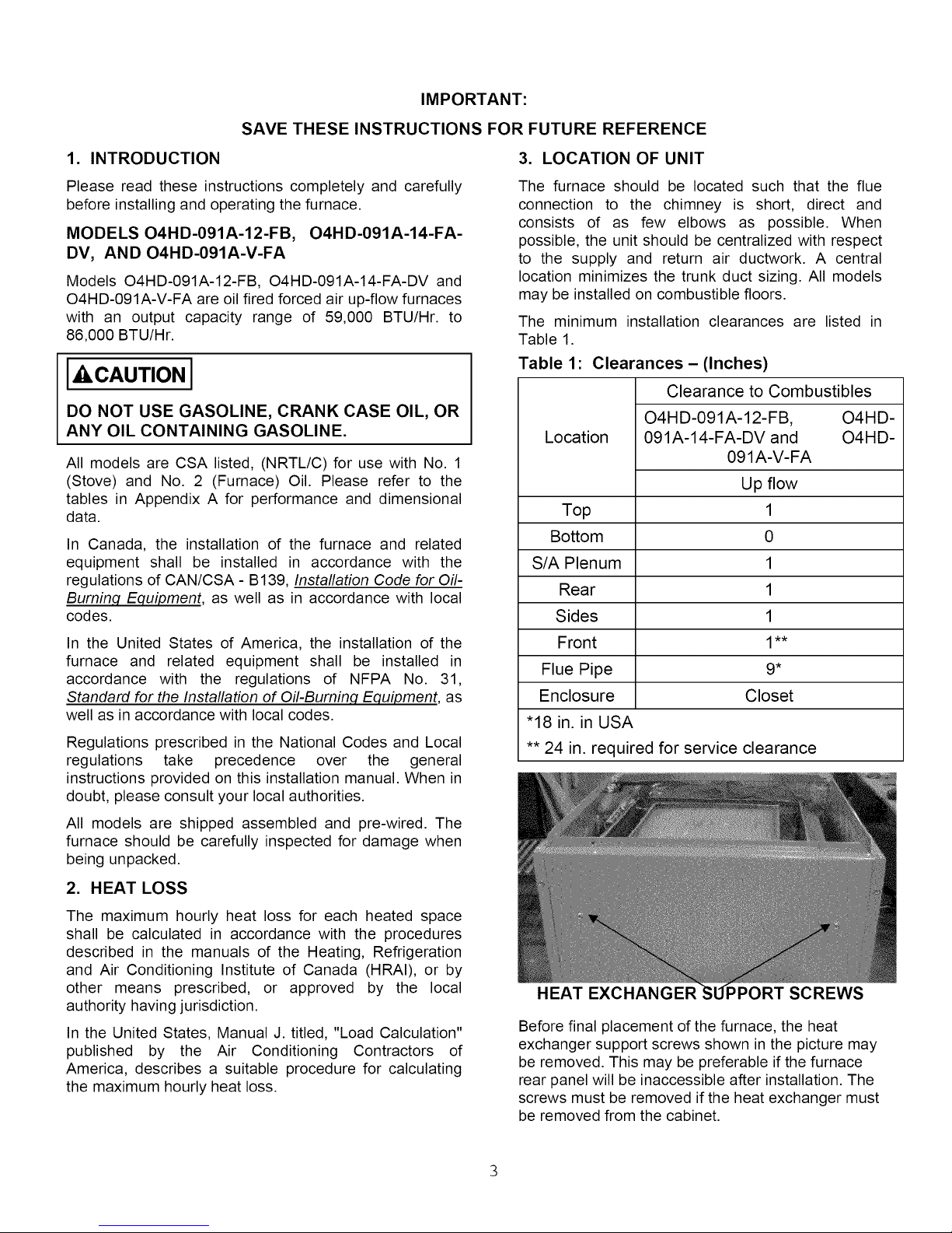
HEAT EXCHANGER _PORT SCREWS
Before final placement of the furnace, the heat
exchanger support screws shown in the picture may
be removed. This may be preferable if the furnace
rear panel will be inaccessible after installation. The
screws must be removed if the heat exchanger must
be removed from the cabinet.
4. AIR CONDITIONING APPLICATIONS
If the furnace is used in conjunction with air conditioning,
the furnace shall be installed in parallel with or upstream
from the evaporator coil to avoid condensation in the
heat exchanger. In a parallel installation, the dampers or
air controlling means must prevent chilled air from
entering the furnace. If the dampers are manually
operated, there must be a means of control to prevent
the operation of either system unless the dampers are in
the full heat or full cool position. The air heated by the
furnace shall not pass through a refrigeration unit unless
the unit is specifically approved for such service.
The blower speed must be checked and adjusted to
compensate for the pressure drop caused by the
evaporator coil. Refer to Appendix B for recommended
wiring and electrical connections of the air conditioning
controls.
5. COMBUSTION AIR
If the furnace is installed in a closet or utility room, two
openings must be provided connecting to a well-
ventilated space (full basement, living room or other
room opening thereto, but not a bedroom or bathroom).
One opening shall be located above the level of the
upper vent opening and one opening below the
combustion air inlet opening in the front of the furnace.
Each opening shall have a minimum free area of 1½
square inches per 1,000 Btu/h of total input rating of all
appliances installed in the room.
regulations, to the requirements of the National
Building Code.
NOTE: THE FURNACE IS APPROVED FOR
USE WITH TYPE L VENT OR EQUIVALENT.
I I cAuTION I
CHIMNEY VENTED VERSIONS OF
FURNACE MUST BE CONNECTED TO A
FLUE HAVING SUFFICIENT DRAFT
TIMES TO ENSURE SAFE AND
OPERATION OF THE APPLIANCE.
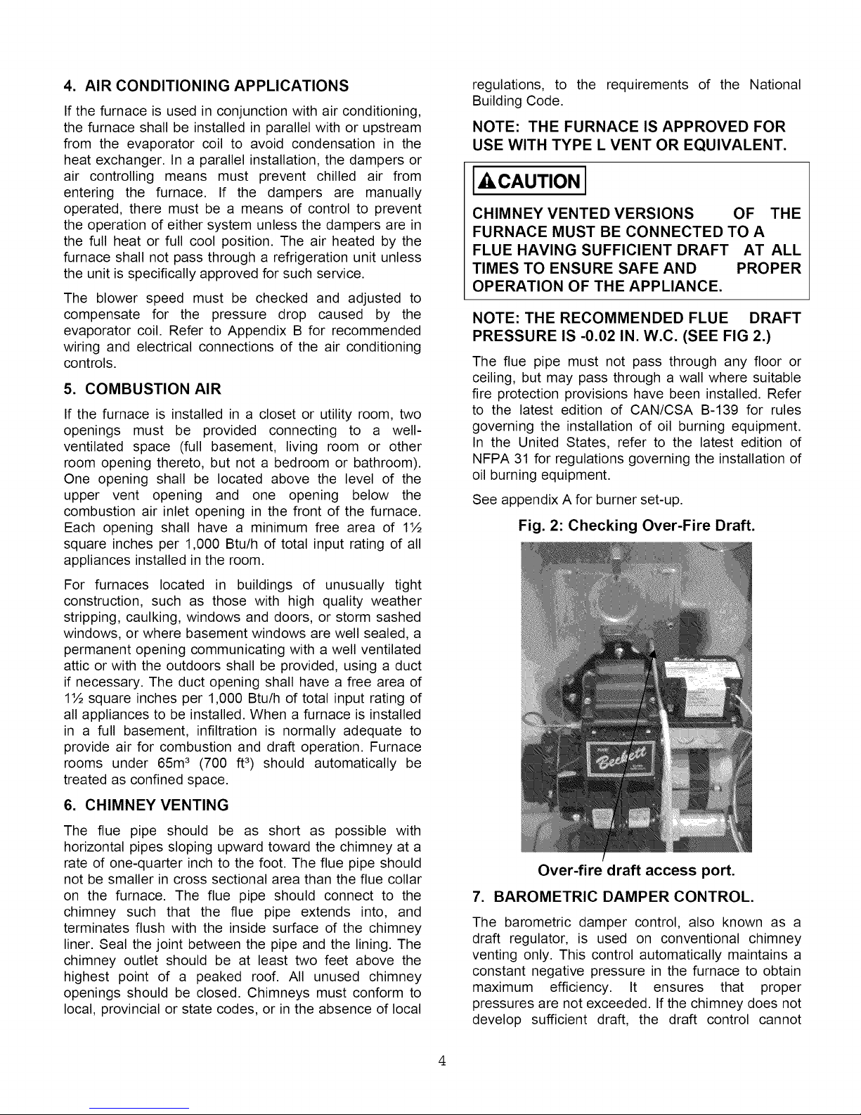
NOTE: THE RECOMMENDED FLUE DRAFT
PRESSURE IS -0.02 IN. W.C. (SEE FIG 2.)
The flue pipe must not pass through any floor or
ceiling, but may pass through a wall where suitable
fire protection provisions have been installed. Refer
to the latest edition of CAN/CSA B-139 for rules
governing the installation of oil burning equipment.
In the United States, refer to the latest edition of
NFPA 31 for regulations governing the installation of
oil burning equipment.
See appendix A for burner set-up.
Fig. 2: Checking Over-Fire Draft.
THE
AT ALL
PROPER
For furnaces located in buildings of unusually tight
construction, such as those with high quality weather
stripping, caulking, windows and doors, or storm sashed
windows, or where basement windows are well sealed, a
permanent opening communicating with a well ventilated
attic or with the outdoors shall be provided, using a duct
if necessary. The duct opening shall have a free area of
1½ square inches per 1,000 Btu/h of total input rating of
all appliances to be installed. When a furnace is installed
in a full basement, infiltration is normally adequate to
provide air for combustion and draft operation. Furnace
rooms under 65m3 (700 ft3) should automatically be
treated as confined space.
6. CHIMNEY VENTING
The flue pipe should be as short as possible with
horizontal pipes sloping upward toward the chimney at a
rate of one-quarter inch to the foot. The flue pipe should
not be smaller in cross sectional area than the flue collar
on the furnace. The flue pipe should connect to the
chimney such that the flue pipe extends into, and
terminates flush with the inside surface of the chimney
liner. Seal the joint between the pipe and the lining. The
chimney outlet should be at least two feet above the
highest point of a peaked roof. All unused chimney
openings should be closed. Chimneys must conform to
local, provincial or state codes, or in the absence of local
Over-fire draft access port.
7. BAROMETRIC DAMPER CONTROL.
The barometric damper control, also known as a
draft regulator, is used on conventional chimney
venting only. This control automatically maintains a
constant negative pressure in the furnace to obtain
maximum efficiency. It ensures that proper
pressures are not exceeded. If the chimney does not
develop sufficient draft, the draft control cannot
functionproperly.The draft regulator,wheninstalled
shouldbeinthesameroomorenclosureasthefurnace
andshouldnotinterferewiththecombustionairsupplied
to the burner.Thecontrolshouldalsobelocatednear
the furnaceflue outletand installedaccordingto the
instructionssuppliedwiththeregulator.Theflueoutlet
pressure(measuredbetweenthe furnaceand draft
regulator,ortheoilburnermountingplateover-fireddraft
accessport.fig.2)shouldbesetto-0.02in.w.c.
8. OPTIONAL SIDE WALL VENTING
O4HD-091A-14-FA-DV furnace models are
manufactured to be installed as sidewall vented units.
Please refer to Direct Venting Instructions, P/N
240005236 included with the Vent Kit for details. Sidewall
Venting (Direct Venting) requires the use of a specific oil
burner; the Beckett AFII. Please refer to Appendix A,
Table A2.
Note: Sidewall venting requires special attention to
combustion air supply. There is no natural draft in the
venting system between furnace cycles; therefore, if the
indoor pressure is negative relative to the outdoors, the
vent terminal becomes a point of infiltration. This could
lead to oil odour control problems. This problem is
rectified by the use of ducted outdoor air for combustion
(semi-sealed combustion), using the Beckett AFII oil
burner. See Direct Vent Instructions supplied with the
Vent Kits.
9a. FAN TIMER BOARD AND LIMIT CONTROL
(FIG. 4) (page 22)
The Electronic Fan Timer integrates control of all burner
and circulator fan operations. This control is the central
wiring point for most of the electrical components in the
furnace. The United Technologies 1158-120 (O4HD-
091A-12-FB and O4HD-091A-14-FA-DV) has an
adjustable fan on time that is set by selecting the
dipswitch combination displayed in Chart 1. This fan on
delay can be set at 1, 2, 4 or 6 minutes. This provides a
delay between the burner ignition and blower start-up to
eliminate excessive flow of cold air when the blower
comes on. The United Technologies 1158-120 (O4HD-
091A-12-FB and O4HD-091A-14-FA-DV) has an
adjustable fan off time of 30, 60, 90 or 120 seconds
displayed in Chart 1. The fan off delay time starts when
the burner motor is de-energized at the end of a call for
heat. Blower shutdown is delayed to remove any residual
heat from the heat exchanger and improve the annual
efficiency of the furnace.
The electronic fan timer board works in conjunction with
snap disc limit controls, which perform a safety function,
and breaks power to the oil burner primary control, which
shuts off the burner if the furnace over-heats. The limit
control is thermally operated and automatically resets.
The limit control is factory installed, pre-set and is not
adjustable.
If the limit control opens with the United
Technologies 1158-120 (O4HD-091A-12-FB and
O4HD-091A-14-FA-DV) electronic fan control, the
circulating fan will be energized as well. When the
limit closes, the fan off timer will begin. At the end of
the fan off time cycle the burner will be energized,
initiating a normal burner cycle.
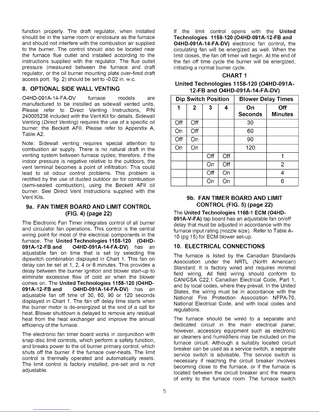
CHART 1
United Technologies 1158-120 (O4HD-091A-
12-FB and O4HD-091A-14-FA-DV)
Dip Switch Position Blower Delay Times
1 2 3 4 On Off
Seconds Minutes
Off Off 30
On Off 60
Off On 90
On On 120
Off Off 1
On Off 2
Off On 4
On On 6
9b. FAN TIMER BOARD AND LIMIT
CONTROL (FIG. 5) (page 22)
The United Technologies 1168-1 ECM (O4HD-
091A-V-FA) tap board has an adjustable fan on/off
delay that must be adjusted in accordance with the
furnace input rating (nozzle size). Refer to Table A-
10 (pg 15) for ECM blower set-up.
10. ELECTRICAL CONNECTIONS
The furnace is listed by the Canadian Standards
Association under the NRTL (North American)
Standard. It is factory wired and requires minimal
field wiring. All field wiring should conform to
CAN/CSA C22.1 Canadian Electrical Code, Part 1,
and by local codes, where they prevail. In the United
States, the wiring must be in accordance with the
National Fire Protection Association NFPA-70,
National Electrical Code, and with local codes and
regulations.
The furnace should be wired to a separate and
dedicated circuit in the main electrical panel;
however, accessory equipment such as electronic
air cleaners and humidifiers may be included on the
furnace circuit. Although a suitably located circuit
breaker can be used as a service switch, a separate
service switch is advisable. The service switch is
necessary if reaching the circuit breaker involves
becoming close to the furnace, or if the furnace is
located between the circuit breaker and the means
of entry to the furnace room. The furnace switch
(serviceswitch)shouldbeclearlymarked,installedinan
easilyaccessibleareabetweenthefurnaceandfurnace
roomentry,andbelocatedinsucha mannerto reduce
thelikelihoodthatitwouldbemistakenasa lightswitch
orsimilardevice.
The power requirementfor the O4HD-091A-12-FB,
O4HD-091A-14-FA-DVandO4HD-091A-V-FAmodelsis:
120VAC,10, 60Hz.,12A.
In the United States the installation must be in
accordance with NFPA No. 31 and local codes and
authorities.
Install the oil filter as close to the burner as possible.
For further details of the oil supply tank and piping
requirements, please refer to the instructions and
illustrations in the oil burner and oil pump
instructions shipped with the furnace.
Accessoriesrequiring120VACpowersourcessuchas
electronicair cleanersandhumidifiertransformersmay
be poweredfromthe electronicfan timerboardwhere
provisionshavebeenmadefor connections,butshould
havetheirowncontrols.Donotusethedirectdrivemotor
connectionsasapowersource,sincethereisa highrisk
ofdamagingtheaccessoriesbyexposuretohighvoltage
fromthe auto-generatingwindingsof the directdrive
motor.
Thermostatwiring connectionsand air conditioning
contactorlow voltageconnectionsare shownin the
wiringdiagramsin AppendixB. Somemicro-electronic
thermostatsrequireadditionalcontrolsandwiring.Refer
tothethermostatmanufacturer'sinstructions.
Thethermostatshouldbe locatedapproximately5feet
abovethefloor,on an insidewallwherethereis good
naturalair circulation,andwherethethermostatwillbe
exposedto averageroomtemperatures.Avoidlocations
wherethethermostatwillbeexposedtocolddrafts,heat
fromnearbylampsandappliances,exposuretosunlight,
heatfrominsidewallstacks,etc.
Thethermostatheatanticipatorshouldbeadjustedtothe
amperagedraw of the heating control circuit as
measuredatthe"R"and"W"terminalsofthethermostat.
Toreducetheriskof damagingthe heatanticipator,do
notmeasurethiscurrentwiththethermostatconnected
to thecircuit.Measuretheamperagebyconnectingan
ammeterbetweenthetwowiresthatwillconnecttothe
thermostat"R"and"W"terminals.
11. HUMIDIFIER
A humidifier is an optional accessory available through
most heating supplies outlets. Installation should be
carried out in accordance with the humidifier
manufacturer's installation instructions. Water or water
droplets from the humidifier should not be allowed to
come into contact with the furnace heat exchanger. Do
not use direct drive motor connections as a source of
power for 120 VAC humidifiers and humidifier
transformers.
12. PIPING INSTALLATION
The entire fuel system should be installed in accordance
with the requirement of CAN/CSA B-139, and local
regulations. Use only an approved fuel oil tanks piping,
fittings and oil filter.
13. OIL FILTER
All fuel systems should include an oil filter between
the fuel oil storage tank and the oil burner. When
using an oil burner nozzle smaller than 0.65 U.S.
Gallons Per Hour, install an additional 7 to 10 micron
filter as close as possible to the oil burner.
14. OIL BURNER NOZZLES
The O4HD-091A-12-FB, O4HD-091A-14-FA-DV and
O4HD-091A-V-FA are certified for multiple firing
rates, ranging from 59,000 to 86,000 Btu/h. By
manipulating the oil burner nozzle, flame retention
head, static plate and temperature rise; the furnace
may be fired at an ideal rate for a wide range of
structures. Refer to Table A-l, and the furnace
rating plate to determine the proper combinations.
15. OIL BURNER ADJUSTMENT
The burner air supply is adjusted to maintain the fuel
to air ratio to obtain ideal combustion conditions. A
lack of air causes "soft" and "sooty" flames, resulting
in soot build-up throughout the heat exchanger
passages. Excess combustion air causes a bright
roaring fire and high stack temperatures resulting in
poor fuel efficiency. The O4HD-091A-12-FB, O4HD-
091A-14-FA-DV and O4HD-091A-V-FA furnaces
operate most efficiently with a No. 1 smoke spot on
the Bacharach Scale. This is not necessarily the
optimum setting; however, because dust will
inevitably build up on the air moving components of
the oil burner assembly. This will result in decreased
air supply with the potential result of soot building up
in the flue gas passageways of the heat exchanger.
Soot behaves as an insulator and impairs good heat
transfer. Stack temperature will increase, and the
overall efficiency will decrease. As a means of
avoiding this problem, it is advisable to adjust the air
supply to provide no more than a trace smoke spot
on the Bacharach Scale.
See the Venting Instructions included in the Vent
Kits for set-up details for sidewall vented furnaces.
NOTE: SIDEWALL VENTED MODELS
SHOULD BE SET UP TO DELIVER ZERO (0)
SMOKE.
I'ACAUTION I
I'ACAUTION I
BEFORE OPERATING THE FURNACE CHECK
BURNER ALIGNMENT WITH COMBUSTION
CHAMBER. THE END CONE OF THE AIR TUBE
MUST BE CENTRED TO THE ACCOMODATING
RING PROVIDED IN THE DESIGN OF THE
COMBUSTION CHAMBER. ADJUST AS
NECESSARY.
16. BURNER ELECTRODES
Correct positioning of the electrode tips with respect to
each other, to the fuel oil nozzle, and to the rest of the
burners is essential for smooth light ups and proper
operation. Refer to the oil burner instructions shipped
with the furnace for electrode specifications.
NOTE: Beckett AF Series Burner electrode specifications
have been revised. They should be adjusted to be 5/16"
above the nozzle centerline.
17. BURNER PRIMARY (SAFETY) CONTROL
The furnace is equipped with a primary combustion
control, sometimes referred to as the burner relay or
burner protector relay, which uses a light sensing device
(cad cell) located in the burner housing, to monitor and
control combustion. Over time, dust or combustion
residuals can build up on the lens of the cad cell
impairing its response to the flame. The cad cell should
be checked for cleanliness and proper alignment if the
primary control frequently shuts down combustion.
I'ACAUTION I
ALL FURNACE CONTROLS ARE SENSITIVE
AND SHOULD NOT BE SUBJECTED TO
TAMPERING. IF PROBLEMS PERSIST, CALL
YOUR SERVICE CONTRACTOR.
18. COMBUSTION CHAMBER
This furnace is equipped with a high quality cerafelt
combustion chamber. It is held in place by a retaining
bracket.
CHECK THE ALIGNMENT OF THE COMBUSTION
CHAMBER AND OIL BURNER BEFORE FIRING.
IT IS POSSIBLE FOR THE COMBUSTION
CHAMBER TO SHIFT IF SUBJECTED TO ROUGH
HANDLING DURING TRANSIT. The combustion
chamber should be inspected for damage or carbon build
up whenever the oil burner is removed for repairs or
routine maintenance.
DO NOT START THE BURNER UNLESS THE
BLOWER ACCESS DOOR IS SECURED IN
PLACE.
19a. CIRCULATING AIR BLOWER (O4HD-
091A-12-FB)
The O4HD-091A-12-FB, O4HD-091A-14-FA-DV and
O4HD-091A-V-FA furnace models are equipped
with direct drive blower systems. O4HD-091A-12-
FB and O4HD-091A-14-FA-DV models are
equipped with PSC motors; O4HD-091A-V-FA
models are equipped with electronically commutated
motors (ECM). Direct drive blower speed
adjustments are not normally required in properly
sized extended plenum duct systems. The motor
RPM and air CFM delivery will vary automatically to
accommodate conditions within the usual range of
external static pressures typical of residential duct
systems. Under-sized duct systems may require a
higher blower speed to obtain a reasonable system
temperature rise. Some older duct systems were not
designed to provide static pressure. They typically
feature special reducing fittings at each branch run
and lack block ends on the trunk ducts. These
systems may require modification to provide some
resistance to the airflow to prevent over-amping of
the direct drive blower motor. Selecting a lower
blower speed may correct this problem. Direct drive
blower speeds are adjusted by changing the "hot"
wires to the motor winding connections. Please refer
to wiring diagrams in Appendix B or the wiring
diagram label affixed to the furnace. THE NEUTRAL
WIRE (normally the w hite w ire) IS NEVER
MOVED TO ADJUST THE BLOWER SPEED.
It is possible and acceptable to use a single blower
speed for both heating and cooling modes. The
simplest method to connect the wiring from both
modes is to use a "piggy-back connector"
accommodating both wires on a single motor tap. It
is also acceptable to connect the selected motor
speed with a pigtail joined to both heating and
cooling speed wires with a wire nut. As a safety
precaution against accidental disconnection of the
wires by vibration, it is advisable to secure the wire
nut and wires with a few wraps of electricians tape.
I'ACAUTION I
DO NOT CONNECT POWER LEADS BETWEEN
MOTOR SPEEDS. THE NEUTRAL WIRE MUST
ALWAYS BE CONNECTED TO THE MOTOR'S
DESIGNATED NEUTRAL TERMINAL.
If the joining of the blower speed wiring is done in the
furnace junction box, tape off both ends of the unused
wire.
Do not use the blow er speed w ires as a source of
power to accessories as electronic air cleaners and
humidifier transformers. The unused motor taps auto-
generate sufficiently high voltages to damage accessory
equipment.
20. MAINTENANCE AND SERVICE
Routine Maintenance By Home Owner
Other than remembering to arrange for the annual
professional servicing of the furnace by the service
or installation contractor, the most important routine
service performed by the homeowner is to maintain
the air filter or filters. A dirty filter can cause the
furnace to over-heat, fail to maintain indoor
temperature during cold weather, increase fuel
consumption and cause component failure.
The furnace filter(s) should be inspected, cleaned or
replaced monthly. The furnace is factory equipped
with a semi-permanent type filter. If the filter is
damaged, replace with filters of the same size and
type. (See Appendix A, Table A-8).
I_WARNINGI
DISCONNECT THE POWER SUPPLY TO THE
FURNACE BEFORE OPENING THE BLOWER
ACCESS DOOR TO SERVICE THE AIR FILTER,
FAN AND MOTOR. FAILURE TO SHUT OFF
POWER COULD ALLOW THE BLOWER TO
START UNEXPECTEDLY, CREATING A RISK OF
DEATH OR PERSONAL INJURY.
19b. CIRCULATING AIR BLOWER (O4HD-091A-
V-FA) (See Section 22 Page 9)
During the routine service, inspect the general
condition of the furnace watching for signs of oil
leaks in the vicinity of the oil burner, soot forming on
any external part of the furnace, soot forming around
the joints in the vent pipe, etc. If any of these
conditions are present, please advise your service
or installation contractor.
Annual Service By Contractor
I'ACAUTION I
THE COMBUSTION CHAMBER (FIREPOT) IS
FRAGILE. USE CARE WHEN INSPECTING
AND CLEANING THIS AREA.
The heat exchanger should be inspected
periodically and cleaned if necessary. If cleaning is
necessary, SHUT OFF POWER TO THE FURNACE
and remove the burner. Using a stiff brush with a
wire handle, brush off scale and soot from insidethe
drum and flue pipe. To clean the radiator, remove
the clean-out caps screws, and remove the caps
carefully to avoid tearing the gaskets. A wire brush
can be used to loosen dirt and debris on the inside
surfaces of the radiator. Clean out all accumulated
dirt, soot and debris with a wire handled brush and
an industrial vacuum cleaner. Before replacing the
clean-out caps, inspect the gaskets. If the gaskets
are broken, remove the remnants and replace with
new gaskets.
The blower motor is factory oiled and permanently
sealed. DO NOT LUBRICATE. Excess oil causes
premature electric motor failure.
Inspect the blower fan. Clean if necessary.
Oil Burner Maintenance: Follow the instructions of
the oil burner manufacturer. (See oil burner
manufacturer's instructions supplied with furnace or
burner). It is advisable to change the oil burner
nozzle and oil filter on an annual basis.
8
Theventingsystemshouldbecleanedandinspectedfor
signsof deterioration.Replacepittedor perforatedvent
pipeandfittings.Thebarometricdampershouldopen
andclosefreely.
All electricalconnectionsshouldbe checkedto ensure
tightconnections.Safetycontrolssuchasthehighlimit
controlsshouldbetestedforfunctionality.Thefancontrol
shouldbe checkedto ensurethatthe fanon andoff
delayfunctioncontinuestostartandstoptheblowerfan
attheoptimalsettings.
test is complete, shut off electrical power to the
furnace, replace the neutral wire to the blower fan
motor, and then restore power. The blower fan will
start up immediately. Once the temperature has
dropped and the limit control has reset, the fan will
operate until the fan off time is achieved. The oil
burner will then resume operation and continue until
the thermostat is satisfied. Restore the thermostat
setting to a comfortable temperature.
To Shut Down Unit
21. OPERATING INSTRUCTIONS (O4HD-091A-
12-FB AN D O4HD-091A-14-FA-DV)
Before Lighting
Open all supply and return air registers and grilles.
Open all valves in oil pipes.
Turn on electric power supply
To Light Unit
Set the thermostat above room temperature to call for
heat. The burner should start. NOTE: It may be
necessary to press the RESET button on the primary
combustion control relay.
There will be a fan on time delay before the circulating
fan is energized. The United Technologies 1158-120
has an adjustable fan on time that is set by selecting the
dipswitch combination displayed in Chart 1. This fan on
delay can be set at 1,2, 4 or 6 minutes.
Set the thermostat below room temperature. The oil
burner should stop.
The air circulation blower will continue to run until the
time off setting selected on the electronic fan timer
control times out. The United Technologies 1158-120
has an adjustable fan off time of 30, 60, 90 or 120
seconds. The fan timer control adjustments may be
altered if the air at the room registers is uncomfortably
high upon blower start up or shutdown.
The necessary adjustments to the fan control settings
should be determined by measuring the temperature of
the air in the supply air take-off, or within the first few
inches of the supply air trunk. The side mid point of the
transition is usually ideal, providing that the thermometer
probe is beyond the "line of sight" wherein false readings
from radiant heat could be observed. System
temperature rise is the difference in temperature
between the supply air and return air.
To check the operation of the limit switch, shut off power
to the furnace. Temporarily remove the neutral wire from
the direct drive blower motor. Restore the electrical
power to the furnace and set the thermostat above room
temperature.
After three or four minutes of burner operation, the limit
control should turn the burner off. When the limit function
Set the thermostat to the lowest possible setting.
Set the manual switch (if installed) in the Electrical
Power Supply Line to "OFF".
21. OPERATING INSTRUCTIONS (O4HD-
091A-V-FA)
Before Lighting
Open all supply and return air registers and grilles.
Open all valves in oil pipes.
Turn on electric power supply
To Light Unit
Set the thermostat above room temperature to call
for heat. The burner should start. NOTE: It may be
necessary to press the RESET button on the
primary combustion control relay.
There will be a fan on time delay before the
circulating fan is energized. The United
Technologies 1168-1 has an adjustable fan on/off
time delay that is programmed into the ECM motor,
and is set by selecting the SW4 DIP switch
combination displayed in Table A-10 page 15. Fan
on/off delay must be adjusted according to input
(nozzle size).
1. Set the thermostat below room temperature. The
oil burner should stop.
The air circulation blower will continue to run until
the blower off delay setting programmed into the
ECM motor times out.
To check the operation of the limit switch, shut off
power to the furnace. Temporarily remove the 5 pin
power connector plug from the ECM blower motor.
NOTE: Isolate the AC Line pins on the 5 pin
power connector with electrical tape to prey ent
electric shock hazard. Restore the electrical
power to the furnace and set the thermostat above
room temperature.
After three or four minutes of burner operation, the
limit control should turn the burner off. When the
limit function test is complete, shut off electrical
power to the furnace, replace the 5 pin power plug to
the blower fan motor, and then restore power. The
blower fan will start up immediately. Once the
temperaturehasdroppedandthelimitcontrolhasreset,
thefanwilloperateuntilthefanofftimeisachieved.The
oilburnerwillthenresumeoperationandcontinueuntil
thethermostatissatisfied.Restorethethermostatsetting
toacomfortabletemperature.
NOTE: IF THE FURNACE IS TO BE SHUT DOWN
FOR AN EXTENDED PERIOD OF TIME, CLOSE
THE OIL SUPPLY VALVE TO THE BURNER.
I'ACAUTION I
DO NOT ATTEMPT TO START THE BURNER
WHEN EXCESS OIL HAS ACCUMULATED,
WHEN THE FURNACE IS FULL OF VAPOUR, OR
WHEN THE COMBUSTION CHAMBER IS VERY
HOT. NEVER BURN GARBAGE OR PAPER IN
THE FURNACE, AND NEVER LEAVE PAPER OR
RAGS AROUND THE UNIT.
22. ECM BLOWER MOTOR OPERATION
(O4HD-091A-V-FA)
Setting Blower "ON" and "OFF" Timings
Blower on/off time delays are handled by ECM
motor programming. Features of this ECM variable
speed motor are that it will deliver a constant airflow
within a wide range of external static pressures, and
also includes:
Soft Start: This ECM variable speed motor will
slowly ramp up to the required operating speed.
This feature in the heating cycle allows the heat
exchanger to reach operating temperature before
the set heat speed, which minimizes noise and
increases comfort.
Soft Stop: At the end of the heating cycle, the ECM
variable speed motor will slowly ramp down. This
feature allows for increased energy efficiency and
reduced noise levels.
Dehumidification: A dehumidification feature has
been programmed into the variable speed motor. At
the start of each cooling cycle, the variable speed
motor will run at 82% of the rated airflow for 7.5
minutes. After 7.5 minutes has elapsed, the motor
will increase to 100% of the rated airflow. This
profile is used to provide dehumidification and
improve system efficiency.
Continuous Fan Operation : When the thermostat
continuous fan (G) switch is on without a call for
heating or cooling, the indoor fan is immediately
energized up to 50% of the cooling speed. This
feature allows continuous circulation of air between
calls for heating or cooling.
If a call for heat (W) or cool (Y) occurs during
continuous fan, the blower will remain energized
10
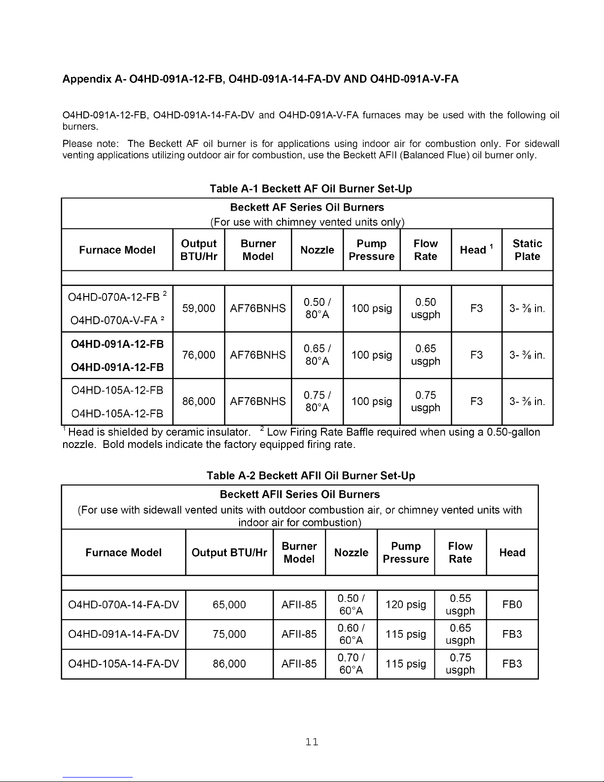
Appendix A- O4HD-091A-12-FB, O4HD-091A-14-FA-DV AN D O4HD-091A-V-FA
O4HD-091A-12-FB, O4HD-091A-14-FA-DV and O4HD-091A-V-FA furnaces may be used with the following oil
burners.
Please note: The Beckett AF oil burner is for applications using indoor air for combustion only. For sidewall
venting applications utilizing outdoor air for combustion, use the Beckett AFII (Balanced Flue) oil burner only.
Table A-1 Beckett AF Oil Burner Set-Up
Beckett AF Series Oil Burners
(For use with chimney vented units only)
Furnace Model Output Burner Nozzle Pump Flow Head 1 Static
BTU/Hr Model Pressure Rate Plate
O4HD-070A-12-FB 2
0.50 / 0.50
59,000 AF76BNHS 100 psig F3 3-¾in.
O4HD-070A-V-FA 2 80°A usgph
O4HD-091A-12-FB 0.65 / 0.65
O4HD-091A-12-FB
76,000 AF76BNHS 80OA 100 psig usgph F3 3-¾in.
O4HD-105A-12-FB 0.75 / 0.75
O4HD-105A-12-FB
86,000 AF76BNHS 80OA 100 psig usgph F3 3-¾in.
Head is shielded by ceramic insulator. _ Low Firing Rate Baffle required when using a 0.50-gallon
nozzle. Bold models indicate the factory equipped firing rate.
Table A-2 Beckett AFII Oil Burner Set-Up
Beckett AFII Series Oil Burners
(For use with sidewall vented units with outdoor combustion air, or chimney vented units with
indoor air for combustion)
Furnace Model Output BTU/Hr Burner Nozzle Pump Flow Head
O4HD-070A-14-FA-DV 65,000 AFII-85 60OA 120 psig usgph FB0
O4HD-091A-14-FA-DV 75,000 AFII-85 60OA 115 psig usgph FB3
O4HD-105A-14-FA-DV 86,000 AFII-85 60OA 115 psig usgph FB3
Model Pressure Rate
0.50 / 0.55
0.60 / 0.65
0.70 / 0.75
11
 Loading...