

Page 1
Residential Gas Furnaces
Installation Instructions
80+ High Efficiency Upflow/Horizontal and Downflow
with Variable Speed Blower
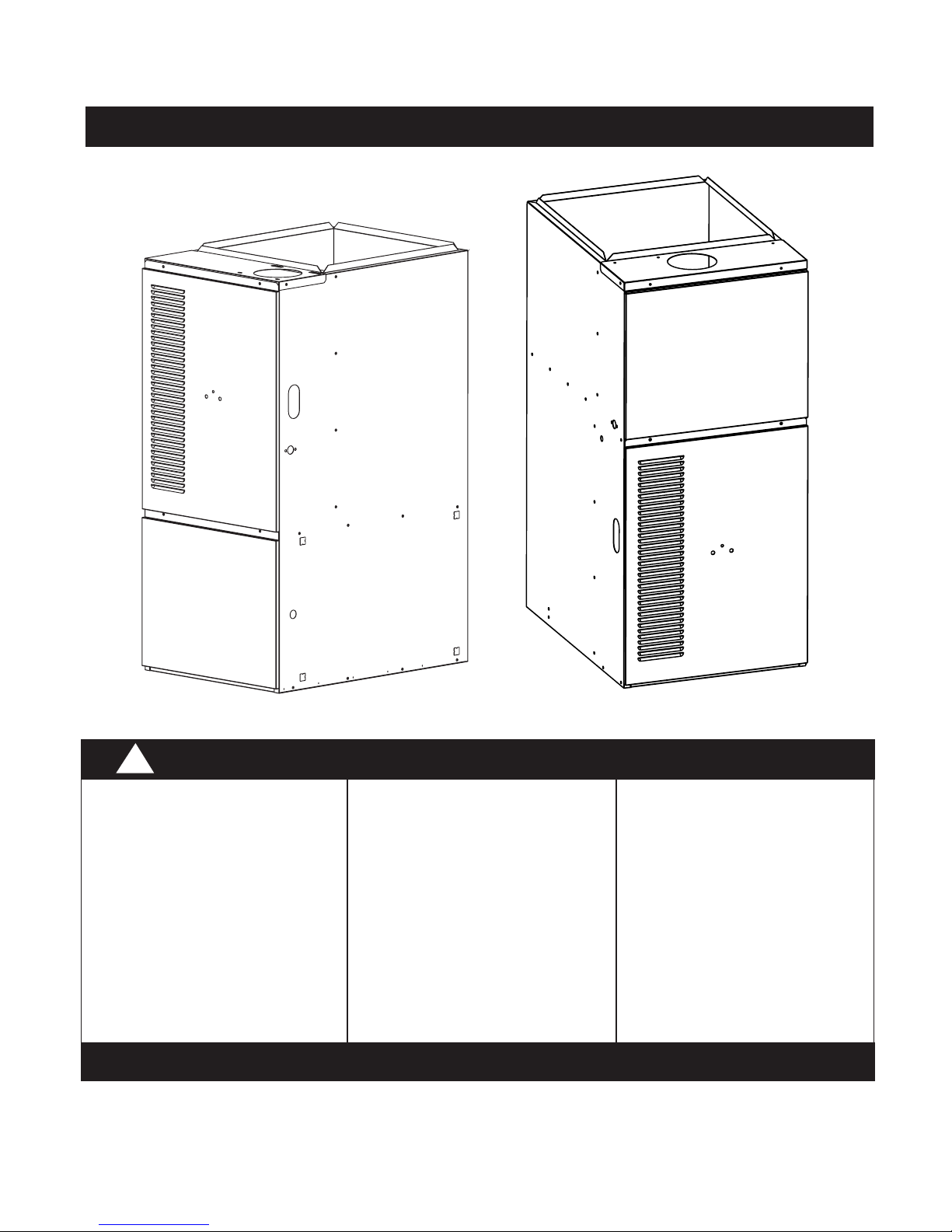
*RA 80+ Upflow
!
WARNING:
Improper installation,
adjustment, alteration,
service, or maintenance can
cause injury or property
damage. Refer to this
manual. For assistance or
additional information
consult a qualified installer,
service agency, or the gas
supplier.
DO NOT DESTROY. PLEASE READ CAREFULLY AND KEEP IN A SAFE PLACE FOR FUTURE REFERENCE.
These instructions are primarily intended to assist qualified individuals experienced in the proper installation of this
appliance. Some local codes require licensed installation/service personnel for this type of equipment. Read all
instructions carefully before starting the installation.
FOR YOUR SAFETY
Do not store or use gasoline
or other flammable vapors
and liquids in the vicinity of
this or any other appliance.
*RK 80+ Downflow
FOR YOUR SAFETY
WHAT TO DO IF YOU SMELL GAS
• Do not try to light any
appliance.
• Do not touch any electrical
switch; do not use any
phone in your building.
• Immediately call your gas
supplier from a neighbor's
phone. Follow the gas
supplier's instructions.
• If you cannot reach your gas
supplier, call the fire
department.
• Extinguish any open flame.
Page 2

Page 3

Table of Contents
Furnace Specifications ....................................................................................................................................................... 4-5
Unit Dimensions and Shipping Weights ....................................................................................................... 4-5
Capacities-Furnace Airflow Data ..................................................................................................................... 6
Safety Information ............................................................................................................................................ 7
Installation Requirements ..................................................................................................................................................... 7
Requirements and Codes ................................................................................................................................ 7
Location............................................................................................................................................................ 7
Clearances to Combustibles ........................................................................................................................... 7
Venting and Combustion Air Requirements ................................................................................................................... 8-13
General ............................................................................................................................................................ 8
Installation in an Unconfined Space ................................................................................................................ 8
Installation in a Confined Space ...................................................................................................................... 8
Horizontal Furnace Installation ........................................................................................................... 1 0
Air From Inside .................................................................................................................................... 11
Outdoor Air Using Vertical Ducts ........................................................................................................ 12
Air Directly Through an Exterior Wall ................................................................................................. 1 2
Outdoor Air Using A Crawl Space and Ventilated Attic ...................................................................... 12
Outdoor Air Through Horizontal Ducts ............................................................................................... 12
Venting Requirements .................................................................................................................................................... 13-19
General .......................................................................................................................................................... 13
Category I - Common Venting ....................................................................................................................... 13
Category III - Horizontal Venting .................................................................................................................... 15
Horizontal Venting for Upflow Models ................................................................................................ 15
Horizontal Power Venting ................................................................................................................... 17
Location of Outdoor Terminations ................................................................................................................. 17
Horizontal Installation ......................................................................................................................... 17
Flexible Vent Systems .................................................................................................................................... 1 9
Circulating Air Supply ..................................................................................................................................................... 19-20
General .......................................................................................................................................................... 19
Return Air ....................................................................................................................................................... 19
Gas Supply and Piping .................................................................................................................................................... 20-22
General .......................................................................................................................................................... 20
Leak Check .................................................................................................................................................... 21
Conversion ..................................................................................................................................................... 2 1
High-Altitude Application ............................................................................................................................... 21
Natural Gas High Altitude Conversion .......................................................................................................... 22
LP/Propane Gas Sea Level and High Altitude Conversion .......................................................................... 22
Electrical Wiring .............................................................................................................................................................. 22-24
General .......................................................................................................................................................... 22
Line Voltage Wiring ........................................................................................................................................ 23
Low Voltage Wiring ........................................................................................................................................ 24
Start-up & Adjustments ....................................................................................................................................................... 24
General .......................................................................................................................................................... 24
Start-Up Procedures ...................................................................................................................................... 24
Verifying and Adjusting Firing Rate ............................................................................................................... 24
Configuring the Blower .................................................................................................................................. 25
Selecting Airflow ............................................................................................................................................ 25
Verifying and Adjusting Temperature Rise .................................................................................................... 26
Verifying Burner Operation ............................................................................................................................ 27
Verifying Operation of Supply Air Limit Switch .............................................................................................. 27
Description of Components ................................................................................................................................................ 28
Wiring Diagram ..................................................................................................................................................................... 30
Maintenance .................................................................................................................................................................... 29-31
Vent System ................................................................................................................................................... 29
Air Filter(s) ...................................................................................................................................................... 29
Lubrication ..................................................................................................................................................... 29
Blower Compartment ..................................................................................................................................... 29
Heat Exchanger and Burner Maintenance .................................................................................................... 29
Cleaning of Flue Passages ............................................................................................................................ 31
Installation/Performance Checklist .................................................................................................................... Back Cover
Page 4
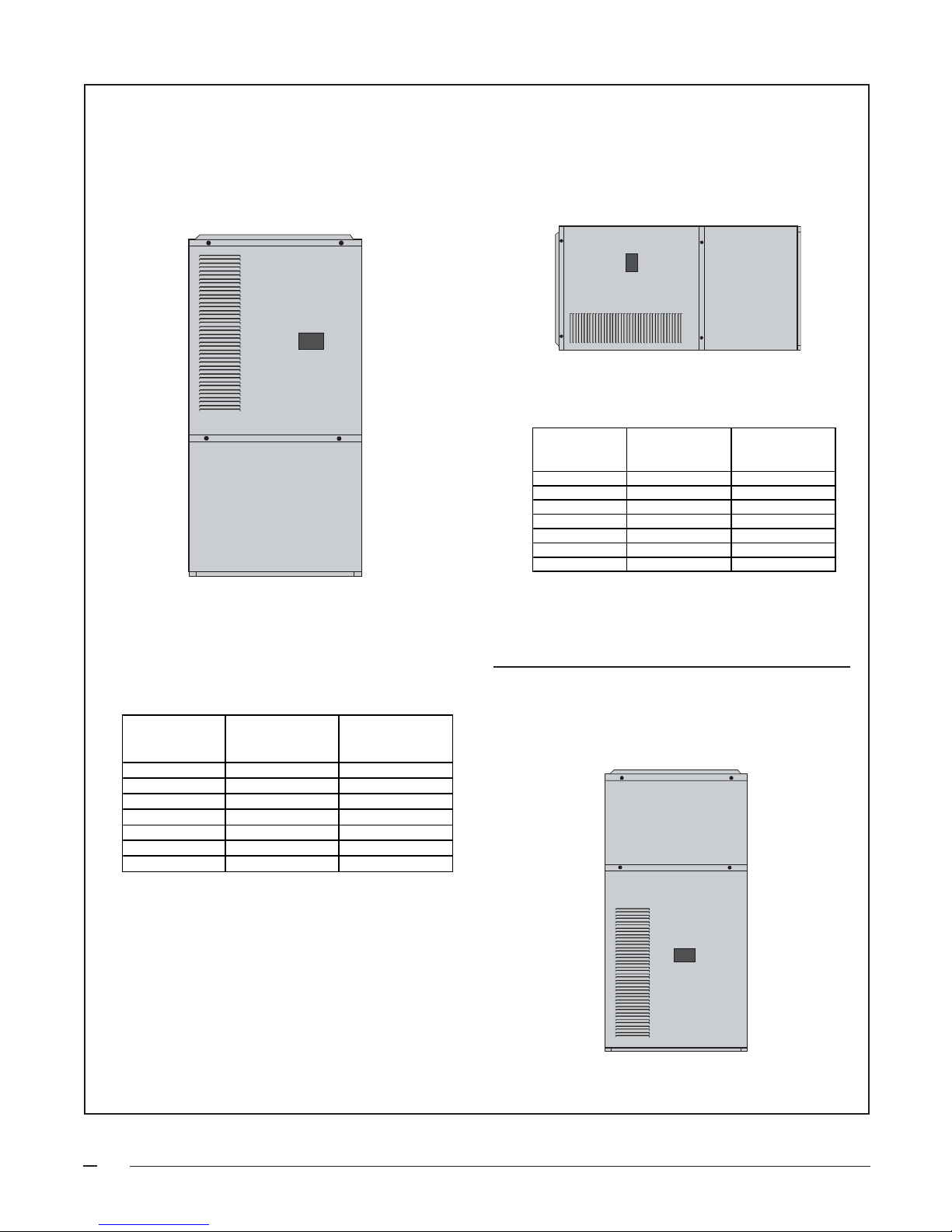
FURNACE SPECIFICATIONS - Upflow/Horizontal Models
3/4
7/8
3/
4
23
3/4
3/
4
19
1/
8
25
1/
1/
2
2
1
X 3
Cut-out for
Gas Connection
7/
8
43
15
1/
4
1
Cut-out for
Electric Connection
25 1/4
Return
Air Opening
(Side)
23
5
27
/8
FLUE
OUTLET
3/4 3/4
33
1/
2
20
1 1/4
A
B
C
Return Air Opening
(Bottom)
30
1 1/4D
Unit Shown in Upflow
Position Rotate 90˚
Clockwise or Counter
Clockwise for Horizontal
Application
1/
2
1
X 3
Gas Connection
7/8 Cut-out for Electric
Connection
1/
4
1/
4
25
1/
2
Cut-out for
5/
8
25
23
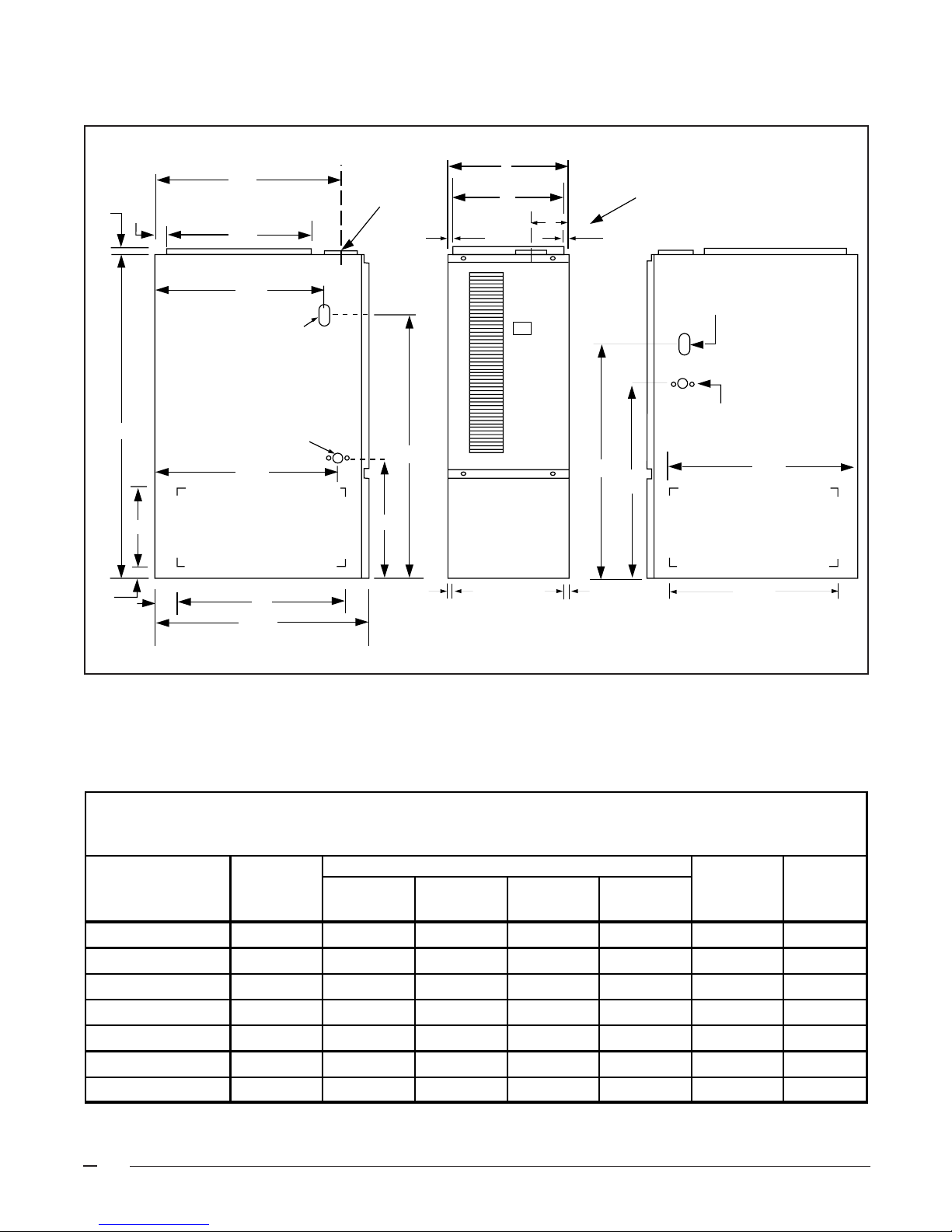
Figure 1a. Upflow Unit Dimensions
FURNACE DIMENSIONS AND
SHIPPING WEIGHTS
Furnace Dimensions Shipping
Model Input A B C Flue Outlet Weight D
*RA (Btuh) (in.) (in.) (in.) (in.) (lbs) (IN.)
072C-16 72,000 19 3/4 18 1/4 3 3/4 4 152 17 1/4
096C-12 96,000 19 3/4 18 1/4 3 3/4 4 163 17 1/4
096C-16 96,000 19 3/4 18 1/4 3 3/4 4 163 17 1/4
096C-20 96,000 22 1/2 21 3 3/4 4 174 20
120C-16 120,000 19 3/4 18 1/4 3 3/4 4 174 17 1/4
120C-20 120,000 22 1/2 21 3 3/4 4 182 20
144C-20 144,000 22 1/2 21 4 1/4 5 194 20
Table 1a. Upflow Furnace Dimensions and Shipping Weights
4
Page 5
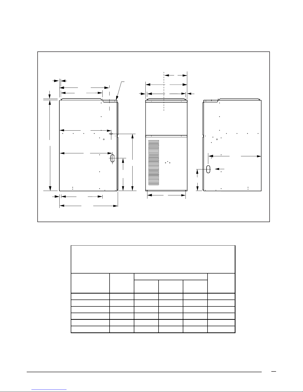
FURNACE SPECIFICATIONS - Downflow Models
3/4"
3/4"
23 5/8"
19 3/4"
4" Dia. Vent
3/4"
A
B
C
3/4"
43"
3/4"
24 1/2"
Cut-out for Electric
Connection
Both sides
25"
Cut-out for Gas Connection
1-1/2 x 3-1/2 (both sides)
19 3/4"
(Bottom Opening)
27 7/8"
C
L
27 1/8"
15 1/2"
C
L
B
(Bottom Opening)
10 1/4"
Figure 1B. Downflow Unit Dimensions
DOWNFLOW FURNACE MODELS
25"
Cut - out for
Gas Connection
FURNACE DIMENSIONS AND
Model Furnace Shipping
Number Input A B C Weights
*RK (Btuh) inches inches inches (lbs)
060C-12 60,000 14 1/4 12 3/4 5 1/2 134
072C-12 72,000 14 1/4 12 3/4 5 1/2 135
072C-16 72,000 19 3/4 18 1/4 11 147
096C-12 96,000 19 3/4 18 1/4 11 154
096C-16 96,000 19 3/4 18 1/4 11 156
120C-20 120,000 19 3/4 18 1/4 11 182
Table 1B. Downflow Furnace Dimensions and Shipping Weights
SHIPPING WEIGHTS
Dime nsions
5
Page 6
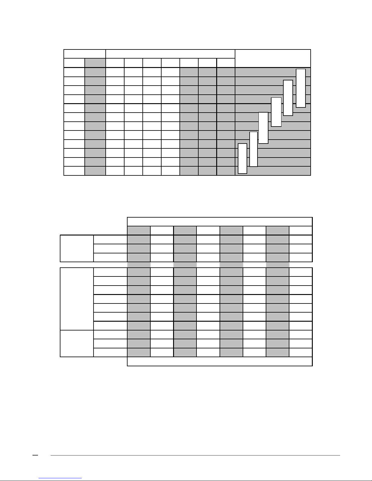
CAPACITIES —Furnace Airflow Data
w
CFM SWITCH NUMBER
LOW HIGH 1 2 3 4
500 720 0 0 0 1
550 800 0 0 0 0
610 880 0 0 1 0
650 945 1 0 0 1
72010501000
80011551010
90013050101
1000 1450 0 1 0 0
1060 1530 1 1 0 1
1100 1595 0 1 1 0
1170 1700 1 1 0 0
1290 1870 1 1 1 0
NOTE: 0 = OFF 1 = ON
Table 1. Cooling/Heat Pump Airflow Settings
720 900 1056 1200 1350 1500 1656 1800
7
6
Switches
5
1
0
0
0
0
0
567
Nominal Air-Flo
1
0
1
0
0
1
1
1
0
Nominal A/C and HP
Capacity
2.5 TON
3 TON
3.5 TON
4 TON
5 TON
0
1
0
1
1
1
2 TON
0
1
1
72,000 59
51
90,000 63
96,000 67 59
108,000 67
120,000 66
126,000 69 62
80+% 92+%
144,000 71
80,000 67
100,000 73 65
120,000 71
Temperature Rise °F (Recommended settings are
NOTE: 0 = OFF 1 = ON
Notes:
1. Recommended temperature rises are highlighted in bold.
2. Airflow rates of 1800 CFM or more require two return air connections. Data is for operation with filter(s).
3. Temperature rises in the table are approximate. Actual temperature rises may vary.
4. Temperature rises that are shaded grey are for reference only. These conditions are not recommended.
5. For single stage cooling, the indoor blower will operate at the CFM listed in the high column.
Table 2. Heating Airflow Settings
44
55
59
49 44
53
59
47
53 48
59
52 47
59
54 49
56
64
51
59
53 49
64
Bold
59
)
6
Page 7

SAFETY INFORMATION
1. Use only with type of gas approved for this furnace.
Refer to the furnace rating plate.
2. Install this furnace only in a location and position as
specified on Table 3 of these instructions.
3. Provide adequate combustion and ventilation air to the
furnace space as specified on Pages 11 through 14.
4. Combustion products must be discharged outdoors.
Connect this furnace to an approved vent system only,
as specified on Pages 13 through 14.
5. Never test for gas leaks with an open flame. Use a
commercially available soap solution made specifically for the detection of leaks to check all connections,
as specified on Page 17 of these instructions.
6. Always install furnace to operate within the furnace’s
intended temperature-rise range with a duct system
which has an external static pressure within the allowable range, as specified on Table 2 of these instructions. See furnace rating plate.
7. When a furnace is installed so that supply ducts carry
air circulated by the furnace to areas outside the space
containing the furnace, the return air shall also be
handled by duct(s) sealed to the furnace casing and
terminating outside the space containing the furnace.
8. A gas-fired furnace for installation in a residential
garage must be installed as specified on Page 6 of
these instructions.
9. The furnace is not to be used for temporary heating of
buildings or structures under construction.
!
WARNING:
This furnace is not approved for installation in
mobile homes. Installation in a mobile home
could cause fire, property damage, and/or
personal injury.
Location
Upflow gas furnaces are shipped ready for installation in the
upflow or horizontal right or left positions. The furnace must
be installed on a level surface, located as close to the vent
(or chimney) and as close to the center of the air distribution
system as possible. See Table 1 for overall dimensions
to determine the required clearances in hallways, doorways,
stairs, etc. to allow the furnace to be moved to the
installation point. The furnace must be installed so that all
electrical components are protected from water. The furnace
must be installed upstream from a refrigeration system.
This furnace is not to be used for temporary heating of
buildings or structures under construction.
Clearances to Combustibles
This furnace is Design Certified by CSA International for
the minimum clearances to combustible material listed in
Table 3. Refer to the furnace rating plate, located inside of
the furnace cabinet, for the specific model number and
clearance information.
INSTALLATION REQUIREMENTS
Requirements and Codes
This furnace must be installed in accordance with these
instructions, all applicable local building codes, current
revision of the National Fuel Gas Code (ANSI-Z223.1), and
in Canada with the CAN/CGA - B149 installation code. The
current revision of the National Fuel Gas Code is available
from:
American National Standards Institute, Inc.
1430 Broadway
New York, New York 10018
Additional helpful publications are:
NFPA-90A - Installation of
Air Conditioning and Ventilating Systems
NFPA-90B - Warm Air Heating
and Air Conditioning Systems
These publications are available from:
National Fire Protection Association, Inc.
Batterymarch Park
Quincy, Massachusetts 02269
Access for positioning and servicing the unit must be
considered when locating unit. 24 inches is the minimum
required clearance from the front of the unit for servicing
it. 30 inches is the minimum required clearance from the
front of the unit for positioning it. 36 inches is the
recommended clearance from the front of the unit.
Please note that a panel or door can be located such that
the minimum clearance on the rating plate is satisfied, but
that panel or door must be removable and allow the
appropriate clearance for your installation.
This furnace is certified for use on wood flooring. This
furnace must not be installed directly on carpeting, tile, or
any combustible material other than wood flooring.
A gas-fired furnace installed in a residential garage must be
installed so the burners and the igniter are located not less
than 18 inches (457 mm) above the floor, and the furnace
must be located or protected to avoid physical damage by
vehicles.
7
Page 8
!
WARNING:
Do not place combustible material on or against
the furnace cabinet or within 6 inches of the vent
pipe. Do not place combustible materials,
including gasoline and any other flammable
vapors and liquids, in the vicinity of the furnace.
VENTING AND COMBUSTION
AIR REQUIREMENTS
General
Provisions must be made in the installation of this furnace
to provide an adequate supply of air for combustion. Detailed
instructions for determining the adequacy of an installation
can be found in the current revision of the National Fuel Gas
Code (ANSI Z223.1 / NFPA54) or in applicable local building
codes. Consult local codes for special requirements.
For Canadian installations consult Canadian Installations
Codes and (CAN/CGA B149.1 or .2).If the furnace is
operated with inadequate air for combustion
one of the flame roll-out switches located in the burner
compartment or the vent switch will open, turning off the
gas supply to the burners. These safety devices are
manually reset switches. DO NOT install jumper wires
across these switches to defeat their function. DO NOT
reset a switch without identifying and correcting the fault
condition. If a switch must be replaced, use only the
correct part specified in the Replacement Parts List.
Air openings in the furnace door, warm air registers, and
return air grilles must not be restricted.
3. The following types of installation may require Outdoor
Air for combustion, due to chemical exposures:
• Commercial buildings
• Buildings with indoor pools
• Furnaces installed in laundry rooms
• Furnaces installed in hobby or craft rooms
• Furnaces installed near chemical storage areas
Exposure to the following substances in the combustion air supply may also require Outdoor Air for
combustion:
• Permanent wave solutions
• Chlorinated waxes and cleaners
• Chlorine based swimming pool chemicals
• Water softening chemicals
• De-icing salts or chemicals
• Carbon tetrachloride
• Halogen type refrigerants
• Cleaning solvents (such as perchloroethylene)
• Printing inks, paint removers, varnishes, etc.
• Hydrochloric acid
• Cements and glues
• Antistatic fabric softeners for clothes dryers
• Masonry acid washing materials
!
WARNING:
Furnace installation using methods other than
those described in the following sections must
comply with the National Fuel Gas Code and all
applicable local codes to provide sufficient
combustion air for the furnace.
!
CAUTION:
Combustion air must not be drawn from a
corrosive atmosphere.
To maximize heat exchanger life, the combustion air must
be free of chemicals which form corrosive acidic compounds
in the combustion gases.
Combustion Air Quality
The recommended source of combustion air is to use the
outdoor air supply. However, the use of indoor air in most
applications is acceptable except as follows:
1. If the furnace is installed in a confined space it is
recommended that the necessary combustion air come
from the outdoors by way of attic, crawl space, air duct,
or direct opening.
2. If outdoor combustion air is used, there must be no
exposure to the installations or substances listed in
Item 3 below.
8
Installation In An Unconfined Space
An unconfined space is an area including all rooms not
separated by doors with a volume greater than 50 cubic feet
per 1,000 Btuh of the combined input rates of all appliances
which draw combustion air from that space.
For example, a space including a water heater rated at
45,000 Btuh input and a furnace rated at 75,000 Btuh
requires a volume of 6,000 cubic feet [50 x (45 + 75) =
6,000] to be considered unconfined. If the space has an 8
foot ceiling, the floor area of the space must be 750 square
feet (6,000 / 8 = 750). In general, a furnace installed in an
unconfined space will not require outside air for combustion.
However, in “tight” buildings (with weather stripping and
caulk to reduce infiltration), it may be necessary to provide
outside air to ensure adequate combustion and venting,
even though the furnace is located in an unconfined space.
Installation In A Confined Space
A confined space is an area with volume less than 50 cubic
feet per 1,000 Btuh of the combined input rates of all
Page 9
appliances drawing combustion air from that space. Furnace
closets, small equipment rooms and garages are confined
spaces. Furnaces installed in a confined space which
supply heated air to areas outside the space must draw
return air from outside the space and must have the return
air ducts tightly sealed to the furnace. A confined space
must have two openings into the space for combustion
air. One opening must be within 12 inches of the
ceiling, and the other must be within 12 inches of the
floor. The required sizing of these openings is determined
by whether inside or outside air is used to support
combustion, the method by which the air is brought to the
space, and by the total input rate of all appliances in the
space.
Downflow Warning (*RK Models):
The design of the downflow furnace is certified for natural
or propane gas and for installation on non-combustible
flooring. A special combustible floor sub-base is required
when installing on a combustible floor. Failure to install the
sub-base may result in fire, property damage and personal
injury. The special downflow sub-bases are factory supplied accessories, part numbers 902677 and 902974.
When the furnace is installed on a factory or site-built cased
air conditioning coil, the sub-base is not necessary. However, the plenum attached to the coil casing must be
installed such that its surfaces are at least 1" from
combustible construction.
Supply Air Plenum Installation
A. Installation on a concrete slab. - *RK
1. Construct a hole in the floor per the dimensions in
Figure 2.
2. Place the plenum and the furnace as shown in Figure
3.
B. Installation on a combustible floor. - *RK
1. Cut and frame the hole in the floor per the dimensions
in Figure 4.
2. Place sub-base for combustible floors over the hole
with its duct collar extended downward. Attach the
supply air plenum to the base in a manner which will
assure 1" clearance to the flooring or other combustible construction. Place furnace on the combustible
base as shown in Figure 6.
3. When a factory or site built cased coil is provided
beneath the furnace the sub-base for combustible
floors is not necessary. However, the plenum attached to the cased coil must be installed such that its
surfaces are at least 1" from the flooring or other
combustible construction.
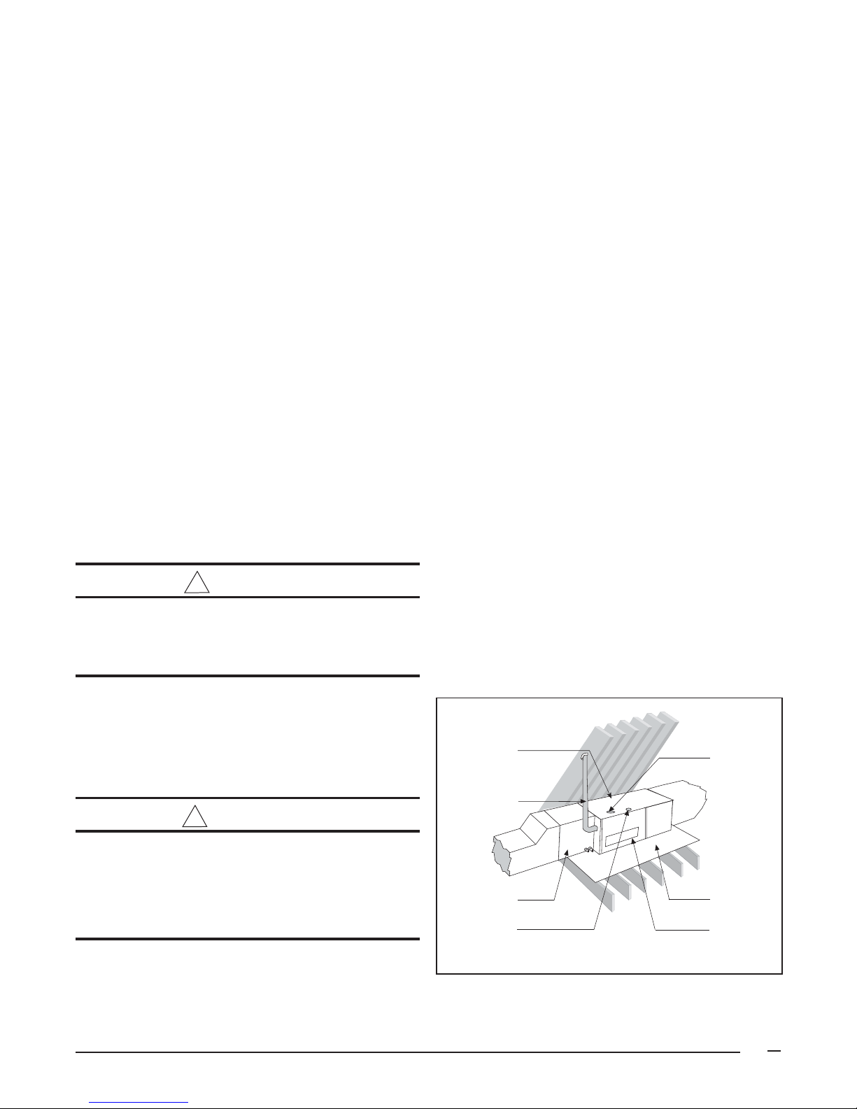
Horizontal Furnace Installation
This furnace can be installed horizontally in an attic,
basement, crawl space or alcove. It can be suspended
from a ceiling in a basement or utility room in either a right
to left airflow or left to right airflow. (See Figure 2.)
!
CAUTION:
The downflow sub-base must not be installed
directly on carpeting, tile, or any combustible
material other than wood flooring.
A gas-fired furnace installed in a residential garage must be
installed so the burners and the igniter are located not less
than 18 inches (457 mm) above the floor, and the furnace
must be located or protected to avoid physical damage by
vehicles.
!
WARNING:
Do not place combustible material on or against
the furnace cabinet or within 6 inches of the
vent pipe. Do not place combustible materials,
including gasoline and any other flammable
vapors and liquids, in the vicinity of the furnace.
If the furnace is to be suspended from the ceiling, it will be
necessary to use steel straps around each end of the
furnace. These straps should be attached to the furnace
with sheet metal screws and to the rafters with bolts. The
furnace could also be suspended by an angle iron frame
bolted to the rafters.
Note: Line
Contact is Permissible
Type “B” Vent
Coil Plenum
Electrical
Supply
Connection
Figure 2. Horizontal installation on a Platform
Gas Inlet
Combustible
Platform
Louver Door
9
Page 10
Upflow Furnace Models
LEFT
SIDE
UPFLOW APPLICATION
TOP
RIGHT
SIDE
BOTTOM
HORIZONTAL APPLICATION
TOP
LEFT
SIDE
BOTTOM
HORIZONTAL INSTALLATION CLEARANCES
Vent Connector
Type
LEFT SIDE
RIGHT SIDE
VENT
BACK
BOTTOM
TOP
FRONT
*** Allow 24" minimum clearance for servicing. The
recommended clearance is 36".
Standard Single
Wall Metal Vent
1" 1"
0" 0"
6" 1"
0" 0"
0" 0"
5" 0"
4"*** 4"***
RIGHT
SIDE
Type B-1 Double
Wall Metal Vent
UPFLOW/DOWNFLOW INSTALLATION CL EARANCES
Vent Connector
Type
LEFT SIDE
RIGHT SIDE
VENT
BACK
BOTTOM
TOP
FRONT
Standard Single
Wall Metal Vent
0" 0"
5"* 0"
6" 1"
0" 0"
0"** 0"**
1" 1"
4"*** 4"***
Type B-1 Double
Wall Metal Vent
* For Downflow furnace installations only,
right side minimum clearance is 0".
** For Downflow furnace installations only,
furnace must be installed on noncombustible flooring.
*** Allow 24" minimum clearance for servicing.
The recommended clearance is 36".
Table 3. Minimum Clearances to Combustible Material
Downflow Furnace Models
DOWNFLOW APPLICATION
TOP
LEFT
SIDE
BOTTOM
RIGHT
SIDE
10
Page 11

Access for positioning and servicing must be considered
when locating the unit. Refer to Table 3, Minimum
Clearances to Combustible Material, for clearance
specifications.
Keep all insulating materials away from the louvered door.
Insulating materials may be combustible.
This furnace may be installed directly on combustible wood
flooring or supports, if type "B-1" vent pipe is used (See
Figure 4). It is recommended for further reduction of fire
hazard that cement board or sheet metal be placed between
the furnace and the combustible floor and extend 12 inches
beyond the front of the louvered door.
18.75"
19.25"
Hole in
Floor
13.25"
19.25"
Hole in
Floor
!
WARNING:
Furnaces installed with combustion air drawn
from a heated space which includes exhaust
fans, fireplaces, or other devices that may
produce a negative pressure should be
considered confined space installations.
See the venting section for venting guidelines and
specifications.
Air From Inside (See Figure 7)
If combustion air is taken from the heated space, the two
openings must
inch per 1,000 Btuh of total input of all appliances in the
confined space, but not less than 100 square inches of
free area. For example, if the combined input rate of all
appliances is less than or equal to 100,000 Btuh, each
opening must have a free area of at least 100 square
inches. If the combined input rate of all appliances is
120,000 Btuh, each opening must have a free area of at
least 120 square inches.
each
have a free area of at least one square
*RK 072-16; 096-12; 096-16;
120-20
*RK 060-12;
072-12
Figure 3a. Opening for Concrete Slab
Concrete
Furnace
Floor
Sheet
Metal
Plenum
Figure 3b. Furnace on a Concrete Slab
18.75"
13.25"
19.63"
Hole in
Floor
*RK 072-16;
096-12; 096-16; 120-20
Hole in
Floor
*RK 060-12;
072-12
19.63"
* Smaller dimensions for *RK
18.75"
or 13.25"*
16.75"
or 11.25"*
19.75"
or 14.25"*
1.50"
060-12; 072-12
9.25"
2.0"
28.38"
19.63"
1.58"
1 inch thick fiberglass 3 lb density
3"
Figure 5. Downflow Sub-Base Dimensions
Downflow
Sub-base
Furnace
Sheet
Metal
Plenum
Wood
Floor
Figure 4. Opening in Wood Floor
Figure 6. Downflow Sub-Base Dimensions
11
Page 12

Outdoor Air Using Vertical Ducts
(See Figure 8)
If combustion air is taken from outdoors through vertical
ducts, the openings and ducts must have a minimum free
area of one square inch per 4,000 Btuh of total appliance
input. In installations drawing combustion air from a ventilated
attic, both air ducts must extend above the attic insulation.
If the unit is installed in an area with an exhaust fan, provide
sufficient ventilation to prevent negative pressures from
occurring in the room.
Vent or
Chimney
Openings to
adjacent space.
Each opening must
be at least 100 sq. in.
or 1 sq. in. per 1000
Btuh of total input
rating, whichever is
greater. See minimum
area per table.
The combustion air openings must not be restricted in any
manner.
!
CAUTION:
Do not supply combustion air from an attic space
that is equipped with power ventilation or any
other device that may produce a negative
pressure.
Air Directly Through An Exterior Wall
(See Figure 9)
If combustion air is provided directly through an exterior
wall, the two openings must each have free area of at least
one square inch per 4000 Btuh of total appliance input.
12" Max.
Furnace
12" Max.
Water Heater
Total Input
Rating (Btu/hr)
40,000
60,000
80,000
100,000
120,000
140,000
160,000
Minimum
Free Area
(Each Opening)
100 sq. in.
100 sq. in.
100 sq. in.
100 sq. in.
120 sq. in.
140 sq. in.
160 sq. in.
Round Duct
Diameter
12"
12"
12"
12"
13"
14"
15"
Figure 7. Equipment in a Confined Space with all
Combustion Air Drawn from the Inside
Vent or
Chimney
Attic
Insulation
Furnace
Water Heater
a. All Combustion Air from Ventilated Attic.
Total Input
Rating (Btu/hr)
40,000
60,000
80,000
100,000
120,000
140,000
160,000
Minimum
Free Area
(Each Opening)
10 sq. in.
15 sq. in.
20 sq. in.
25 sq. in.
30 sq. in.
35 sq. in.
40 sq. in.
Ventilation Louvers at
each end of attic
Outlet Air Duct must
be at least 1 sq. in.
per 4,000 Btuh of
total input rating.
Round Duct
Diameter
4"
5"
5"
6"
6"
7"
8"
Inlet and Outlet
Ducts must
extend above
attic insulation.
Inlet Air Duct must
be at least 1 sq. in.
per 4,000 Btuh of
total input rating.
12" Max
Figure 8. Equipment in a Confined Space with all
Combustion Air Drawn from the Outside
through Vertical Ducts
Outdoor Air Using a Crawl Space and Ventilated
Attic (See Figure 10)
When directly communicating with the outdoors, each
opening shall have a minimum free area of 1 square inch per
4,000 Btuh of total appliance input. The openings shall
communicate directly, or by ducts, with the outdoor spaces
(crawl or attic) that freely communicate with the outdoors.
Outdoor Air Using Horizontal Ducts (See Figure 11)
If combustion air is taken from outdoors through horizontal
ducts, the openings and ducts must have a minimum free
area of one square inch per 2,000 Btuh of total appliance
input.
Vent or
Chimney
Each opening
to outside
must be at least
1 sq. in. per 4000
Btuh of total input
rating.
12" Max
-
-
-
-
-
-
-
-
-
Furnace
-
-
-
-
-
-
-
-
-
12" Max
Total Input
Rating (Btuh)
40,000
60,000
80,000
100,000
120,000
140,000
160,000
Figure 9. Equipment in a Confined Space with all
Combustion Air Drawn from the Outside
through Exterior Wall
Water Heater
Minimum
Free Area
(Each Opening)
10 sq. in.
15 sq. in.
20 sq. in.
25 sq. in.
30 sq. in.
35 sq. in.
40 sq. in.
Round Duct
Diameter
4"
5"
5"
6"
6"
7"
8"
12
Page 13

Vent or
Chimney
Ventilation Louvers at
each end of attic
Attic Insulation
Outlet Air Duct
must be at least
1 sq. in. per 4000
Btuh of total input
rating. Must extend
above attic insulation.
Each opening
to outside
must be at least
1 sq. in. per 2000
Btuh of total input
rating.
Vent or
Chimney
Furnace
Inlet Air Duct must
be at least 1 sq. in.
per 4,000 Btuh of
total input rating.
Water Heater
Ventilation Louvers for
unheated crawl space
Crawl Space
Figure 10. Equipment in a Confined Space with All
Combustion Air Drawn from a
Crawl Space and Ventilated Attic
If the unit is installed in an area with an exhaust fan, provide
sufficient ventilation to prevent negative pressures from
occurring in the room.
The combustion air openings must not be restricted in any
manner.
VENTING REQUIREMENTS
General
This furnace must be vented in compliance with, the current
revision of the National Fuel Gas Code (ANSI-Z223.1/
NFPA54), with the instructions provided below.
-
-
-
-
-
-
-
-
-
-
-
-
-
-
-
-
-
-
12" Max
Rating (Btu/hr)
12" Max
Total Input
40,000
60,000
80,000
100,000
120,000
140,000
160,000
Furnace
Water Heater
(Each Opening)
Minimum
Free Area
20 sq. in.
30 sq. in.
40 sq. in.
50 sq. in.
60 sq. in.
70 sq. in.
80 sq. in.
-
-
-
-
-
-
-
-
Air Duct
-
-
-
-
-
-
-
-
-
Air Duct
-
Round Duct
Diameter
5"
6"
7"
8"
9"
10"
10"
-
-
-
-
-
-
-
-
-
-
-
-
-
-
-
-
-
-
Figure 11. Equipment in a Confined Space with all
Combustion Air Drawn from the Outside through
Horizontal Ducts
should be evenly spaced around the flue diameter, if
possible.
In Canada, venting shall conform to the requirements of the
current (CAN/CGA B149.1 or .2) installation codes. Consult
local codes for special requirements.
This furnace must never be vented to a chimney flue
servicing a fireplace or other appliance designed to burn
solid fuel. If the furnace vent is to be connected to a
chimney serving a fireplace, the fireplace must be sealed
off from the chimney.
For Category I furnace installations, the furnace shall be
connected to a factory built chimney or vent complying with
a recognized standard, or a masonry or concrete chimney
lined with a lining material acceptable to the authority
having jurisdiction. Venting into an unlined masonry
chimney or concrete chimney is prohibited.
The furnace vent, if metal, may be insulated if local codes
allow. Any part of the vent system, metal vent only, not
exposed to weather, but which are exposed to ambient
temperatures below 35° F must be insulated to prevent
condensation. All vent insulation shall be foil backed
fiberglass of one inch minimum thickness.
Three sheet metal fasteners (field supplied) should be used
to secure the vent pipe to the furnace flue. These fasteners
Category I - Common Venting
When an existing furnace is removed from a venting system
serving other appliances, the venting system is likely to be too
large to properly vent the remaining appliances. An improperly
sized venting system can result in the formation of condensate,
leakage, spillage, etc.
The venting system should be designed to have the
minimum number of elbows or turns. All horizontal runs
shall be sloped upwards from the furnace at 1/4 inch per
running foot of vent. Supports for the vent pipe must be
installed a minimum of every five feet along the vent run to
ensure no displacement after installation.
Under no circumstances shall any portion of the vent
system extend into or pass through any return air duct,
supply air duct, or plenum.
If the furnace is operated with blocked or restricted venting,
the blocked vent switch located in the vent plate will open,
turning off the gas supply to the burners. The blocked vent
switch is a manually reset device. DO NOT install a jumper
13
Page 14

!
WARNING:
CARBON MONOXIDE POISONING HAZARD
Failure to follow the steps outlined below for each appliance connected to the venting system
being placed into operation could result in carbon monoxide poisoning or death.
The following steps shall be followed for each appliance connected to the venting system being
placed into operation, while all other appliances connected to the venting system are not in
operation:
1. Seal any unused openings in the venting system.
2. Inspect the venting system for proper size and horizontal pitch, as required in the
National Fuel Gas Code, ANSI Z223. 1/NFPA 54 or the CSA B149.1, Natural Gas and
Propane Installation Codes
and these instructions. Determine that there is no blockage
or restriction, leakage, corrosion and other deficiencies which could cause an unsafe
condition.
3. As far as practical, close all building doors and windows and all doors between the
space in which the appliance(s) connected to the venting system are located and other
spaces of the building.
4. Close fireplace dampers.
5. Turn on clothes dryers and any appliance not connected to the venting system. Turn
on any exhaust fans, such as range hoods and bathroom exhausts, so they are
operating at maximum speed. Do not operate a summer exhaust fan.
6. Follow the lighting instructions. Place the appliance being inspected into operation.
Adjust the thermostat so appliance is operating continuously.
7. Test for spillage from draft hood equipped appliances at the draft hood relief opening
after 5 minutes of main burner operation. Use the flame of a match or candle.
8. If improper venting is observed during any of the above tests, the venting system must
be corrected in accordance with the
or CSA B149.1, Natural Gas and Propane Installation Codes
National Fuel Gas Code, ANSI Z223.1/NFPA 54 and/
.
9. After it has been determined that each appliance connected to the venting system
properly vents when tested as outlined above, return doors, windows, exhaust fans,
fireplace dampers and any other gas-fired burning appliance to their previous conditions
of use.
wire across this switch to defeat its function. DO NOT reset
the switch without identifying and correcting the fault
condition which caused the switch to trip. If this switch
must be replaced, use only the part specified in the
Replacement Parts List.
!
WARNING:
Upon completion of the furnace installation,
carefully inspect the entire flue system both
inside and outside the furnace to assure it is
properly sealed. Leaks in the flue system can
result in serious personal injury or death due to
exposure of flue products, including carbon
monoxide.
14
Category III: Horizontal Venting
NOTE: The reduced NOx models (eighth character N)
are not approved as a Category III furnace for use with
horizontal venting.
The furnaces are approved for use with 3" single wall AL294C stainless steel vent pipe in horizontal vent applications.
This pipe is available from the following manufacturers:
Z-FLEX Inc. - vent brand name (Z-VENT)
Heat-fab Inc. - vent brand name (Saf-T Vent)
Flex-L International - vent brand name (Star-34 Vent)
This vent pipe must be used for the entire length of the vent
run. The installation must be in accordance with all
instructions supplied by the vent manufacturer for use on
Category III appliances. When venting horizontal, this is
Page 15

Cut
Sensor
Tubes
Pressure
Switch
Bleed Tube
Bleed Tube
Orifice
Switch
Limit
Blue
Switch
Flame
Roll-Out
Switch
Vent
Limit
Figure 14. Limit Circuit Wiring
Blue
Wire Nut
Collector
Pan
Figure 12. Bleed Tube Installation
defined as a Category III furnace, the vent pressure is
positive, and the venting system must be sealed in both
horizontal and vertical runs.
For horizontal venting installations in both the United
States and Canada the transition assembly must be modified
by adding a bleed tube to the pressure switch tube and
bypassing the vent switch. All model furnaces will require
Vent Kit #903196 for horizontal venting.
Horizontal Venting For Upflow Models:
1. Remove the rubber tubing from the pressure switch
sensor tube and the collector pan sensor tube. Cut
1/2 inch from one end of the rubber sensor tube, fold
in half and cut along the bend line. Discard the 1/2
inch long piece of tubing. Select the correct bleed
tube using the table supplied with vent kit #903196
and place the other two pieces of tubing on both ends
of the bleed tube. Do not cover the hole in the bleed
tube. Place the assembly back on the pressure
switch sensor tube and the collector pan sensor
tube. (See Figure 12.)
cover the hole(s) on the vent collar assembly.
Tighten the nut securely while holding the cover plate
in position. (See Figure 13.)
3. Bypass the vent switch by removing both wires from
the vent switch and attaching them to the wire nut.
(See Figure 14.)
!
CAUTION:
Do not drill holes through the vent pipe or fittings
on a horizontal vented furnace. Do not use sheet
metal screws, or rivets. Drilling, screws, or
rivets will cause leaks.
The components of the horizontal vent system must not be
penetrated with screws, rivets, or other devices, either
when joining pipes and fittings or using support straps. All
joints must be sealed with high temperature silicone before
locking bands are installed. If the lengths of pipe must be
cut, the joint must still be sealed with silicone and the
locking band used. When installing the condensate tube be
sure to form a trap by means of a 3" loop filled with water.
(See Figure 15.)
Horizontal Venting: *RK Models:
2. Remove the nut and restrictor plate from the vent
collar assembly and discard the restrictor plate.
Select the appropriate dilution cover plate as noted
with vent kit #903196. Fit the clearance hole in the
cover plate over the weld stud. The cover plate must
Covered Vent
Nut
Figure 13. Vent Collar Detail
Collar Hole
Cover
Plate
1. By-pass the vent switch, located on blower compartment door, by removing both wires from the switch.
Remove wire terminals, strip wires and tie together in a
wire nut. (See Figure 16.)
1
/4" Per
Wall Thimble
(For combustible
wall material)
Locking
Band
Termination
Te e
Outside
Wall
Support
0-6'
Locking Band
Te e
Drain
Plug
Foot Rise
3" Dia. Loop
90˚ Elbow
Figure 15. Typical Horizontal Vent Installation
15
Page 16

2. Remove the rubber tubing from the pressure switch
sensor tube and the collector pan sensor tube. Cut the
tubing approximately 3" from one end. Select the
appropriate dilution cover plate as noted with vent kit
#903196. Insert the bleed tube into the tubing. Do not
cover the hole in the bleed tube. Place the tubing
assembly back on the pressure switch sensor tube and
collector pan sensor tube. (See Figure 16.)
3. To gain access to the restrictor plate, remove and
discard the combustion tube from the transition assembly. Insure the seal between inducer and transition
assembly is not broken. (See Figure 17.)
4. Remove and discard the restrictor plate and screw from
the transition assembly. (See Figure 17.)
5. Install and seal a 4" to 3" reducer to the transition. (See
Figure 18.) Attach the new high temperature vent pipe
to the reducer.
NOTE: The direction of the male-female joints from the
drain tee to the termination tee is opposite to standard gas
appliance venting. The male end of the pipes point towards
the furnace.
1. Apply an adhesive bead around the outside of the
pipe approximately 1/4" from the end of the pipe.
This includes the first fitting or pipe attached to the
furnace.
2. Push the pipe and fitting together while twisting the
pipe or fitting. Twisting the pipe or fitting spreads the
adhesive completely within the fitting socket.
3. When the pipe is at the socket bottom, inspect the
joint. Look for a complete, uninterrupted ring of
adhesive material around the pipe at the fitting
socket. Additional adhesive or rotation of the pipe or
fitting may be required for a complete seal. The
The components of the horizontal vent system must not be
penetrated with screws, rivets, or other devices, either
when joining pipes and fittings or using support straps. All
joints must be sealed with high temperature silicone before
locking bands are installed. If the lengths of pipe must be
cut, the joint must still be sealed with silicone and the
locking band used. When installing the condensate tube be
sure to form a trap by means of a 3" loop filled with water.
(See Figure 15.)
Keep the number of pipe fittings to a minimum. Maintain a
minimum of 6 inches of air space between the vent and
combustibles at all times, this includes inside and outside
the building.
Collector
Pan
Bleed Tube
Bleed Tube
Orifice
Pressure
Switch
Combustion
Tube
Remove
and
Discard
Screw
Restrictor
Plate
Transition
Inducer
Figure 17. *RK Horizontal
Vent Modification
Special 3"
AL29-4C Stainless Steel
Vent Pipe
Figure 16. *RK Bleed Tube Installation
16
4" to 3" Reducer
Transition
Figure 18. *RK Reducer Installation
Page 17

complete adhesive material ring provides the seal
required for the positive pressure vent.
4. All vent systems must include a tee and drain plug
for collection and disposal of condensate. The drain
tee must be installed within the first 5 feet of vent run
to protect the furnace.
5. All horizontal sections must have a slope toward the
drain tee of not less than 1/4" per foot to prevent the
collection of condensate at any location other than at
the tee.
6. Horizontal runs must be supported with 3/4" pipe
strap at a maximum of 5 foot intervals and at each
point where an elbow is used.
Installation Instructions are provided with the kit. Installation
must conform to those instructions and applicable
requirements of local codes.
!
WARNING:
The entire vent system must be sealed with a
high temperature sealant which will withstand
temperatures of 450°F. Recommended sealants:
Dow Corning Sealant 736 RTV; GE 106 RTV;
High Tech Ind., High TEMP RED.
Location of Outdoor Terminations
7. Maintain a 6 inch minimum air space to combustibles
from all sections of the stainless steel vent system,
except when a wall thimble is used.
Horizontal Power Venting
— The Tjerlund GPAK-1TN
horizontal kit is certified for use with *RA, *RK Series
furnaces. The kit includes a power venter, a side-wall vent
hood and a barometric draft control. It has an electrical
interlock to assure that the furnace will not operate when
the power venter is off.
The kit is for use only when exhaust is through an exterior
wall, normally with horizontal vent piping. The power venter
establishes negative pressure in the vent piping and the
furnace operates as if connected to Category I vertical
venting.
Horizontal Venting Requirements
Furnace
Model Number Pipe Reducer Maximum Max. Feet
*RA Size Needed # Elbows Vent Pipe
072C-12 3" 4" to 3" 4 35
096C-12 3" 4" to 3" 4 35
096C-16 3" 4" to 3" 4 35
096C-20 3" 4" to 3" 4 35
120C-16 3" 4" to 3" 4 35
120C-20 3" 4" to 3" 4 35
144C-20 3" 4" to 3" 3 30
Note: Special 5" to 4" Reducer Kit, p/n 902249 required for model
number *RA144C-20.
Furnace
Model Number Pipe Reducer Maximum Max. Feet
*RK Size Needed # Elbows Vent Pipe
060C-12 3" 4" to 3" 4 35
072C-12 3" 4" to 3" 4 35
072C-16 3" 4" to 3" 4 35
096C-12 3" 4" to 3" 4 35
096C-16 3" 4" to 3" 4 35
120C-20 3" 4" to 3" 4 35
Table 4. Horizontal Venting Requirements
Horizontal Installation
The vent termination tee must be installed with the following
minimum clearances. (See Figure 19.) Vent Termination
clearances shall be consistant with the National Fuel Gas
Code, ANSI 2223.1/NFPA 54 and/or the CSA B149.1,
Natural Gas and Propane Installation Code.
All minimum clearances specified must be maintained to
protect building material from degradation by flue gases.
1. The termination tee must be 12 inches above
snow level or grade level which ever is higher. See
Figure 14 for alternate method to achieve 12"
above snow level.
2. The minimum distance from any door, (openable)
window, or gravity air inlet is 4 ft. below, 4 ft.
horizontally, or 1 ft. above.
3. The vent termination shall be a minimum of 3 ft. above
any forced air inlet within 10 ft. (See Figure 19.)
4. Recommended minimum distance from an inside
corner formed by two exterior walls is 6 ft., but is not
required.
5. The minimum distance from gas or electric meter(s)
is 4 ft.
6. Avoid areas where condensate drainage may cause
problems such as above planters, patios, or adjacent
to windows where the steam from the flue gases
may cause fogging. Do not terminate above any
public walkway.
7. Select the point of wall penetration where the minimum
1/4 inch per foot of upward slope can be maintained.
8. When penetrating a noncombustible wall, the hole
through the wall must be large enough to maintain the
pitch, pipe clearance for passage, and provide for
proper sealing. Penetrating a combustible wall
requires the use of a wall thimble. (See Figure 20.) A
6-1/2 inch square framed opening is required to insert
the thimble halves. The thimble is adjustable to
varying wall thickness and is held in place by
applying sealant to the male sleeve before assembly.
Also run a bead of sealant around the outer wall
thimble.
17
Page 18

VENT TERMINAL
AIR SUPPLY INLET
AREA WHERE TERMINAL IS NOT PERMITTED
Clearance above grade, v eranda, porch,
A =
Canadian Installations
1
US Installations
12 inches (30 cm) 12 inches (30 cm)
2
deck, or balcony
Clearance to window or door that may be
B =
opened
6 inches (15 c m) f or appl ianc es ≤ 10,0 00
Btuh (3 kW), 12 inches (30 cm) for
4 feet (1.2 m) below or to side of opening;
1 foot (300 mm) above opening
appliances > 10,000 Btuh (3 kW) and ≤
100,00 Btuh (30 kW), 36 inches (91 cm) for
appliances >100,00 Btuh (30 kW)
Clearance to permanently closed window
C =
Vertic al c learance to v entilat ed so ff it
D =
located above the terminal within a
horizont al di st ance of 2 feet (61 c m) f rom
**
**
the center line of t he terminal
Clearance to unventilated soffit
E =
Clearance to outside corner
F =
Clearance to inside corner
G =
Clearance to each side of c enter line
H =
extended above meter/regulator assembly
Clearance to service regulator vent outlet 3 feet (1.83 m)
I =
Clearance to nonmechanical air supply inlet
J =
to building or the combustion air inlet to any
other appliance
3 fe et (91 cm ) wit hin a height 15 f eet
above the meter/regulator assembly
6 inches (15 c m) f or appl ianc es ≤ 10,000
Btuh (3 kW), 12 inches (30 cm) for
appliances > 10,000 Btuh (3 kW) and ≤
**
**
**
*
*
4 feet (1.2 m) below or to side of opening;
1 foot (300 mm) above opening
100,00 Btuh (30 kW), 36 inches (91 cm) for
appliances >100,00 Btuh (30 kW)
Clearance to a mechanical air supply inlet 6 feet (1.83 m) 3 feet (91 cm) above if within 10 feet (3 m)
K =
horizontally
Clearance above paved sidewalk or paved
L =
7 feet (2.13 m) † 7 feet (2.13 m)
driveway located on public property
Clearance under veranda, porch deck, or
M =
balcony
12 inches (30 cm) ‡
*
1
In accordance with the current CSA B149.1 Natural Gas and Propand Installation Code
2
In accordance with the current ANSI Z223.1 / NFPA 54 National Fuel Gas Code
† A vent shall not terminate directly above a sidewalk or paved driveway that is located between two single family dwellings and serves both dwellings.
‡ Permitted only if veranda, porch, deck, or balcony is fully open on a minimum of two sides beneath the floor.
* For clearances not specified in ANSI Z223.1 / NFPA 54 or CSA B149.1, one of the following statements shall be included:
“Clearance in accordance with local installation codes, and the requirements of the gas supplier
18
and the manufacturer’s installation instructions.”
Figure 19. Vent Termination Clearances
Page 19

9. The vent pipe must extend 1-1/4 inches through the
outer thimble half for a combustible wall. Be sure to
check this carefully before cutting the vent pipe.
10. Attach a 3 inch coupling to the end of the pipe that
extends through the wall or thimble. This prevents
the vent pipe from being pushed inward.
11. Cut an 8 inch minimum piece of vent pipe and
connect the coupling to the termination tee. The
inside of the tee must be a minimum of 12 inches
from the outside of the wall. (See Figure 21.)
Flexible Vent Systems
Flexible gas vent is approved for use in vertical single vent
or common vent installations only. The minimum distance
to combustibles is 1" for type B insulated and 6" for single
wall. The venting system must be installed in accordance
with the local authorities, the vent manufacturer's instructions
and the instructions listed below.
The flexible vent must be installed in accordance with the
venting tables for vertical or common venting only. The
vent system must be supported in horizontal runs with
3/4" pipe strap at a maximum of 5 foot intervals. All
horizontal sections must have a slope toward the furnace
of not less than 1/4" per foot. The vent must not sag, or
have any bends greater than 90 degrees.
CIRCULATING AIR SUPPLY
General
Plenums and air ducts must be installed in accordance with
the Standard for the Installation of Air Conditioning and
Ventilating Systems (NFPA No. 90A) or the Standard for
the Installation of Warm Air Heating and Air Conditioning
Systems (NFPA No. 90B).
It is recommended that the outlet duct be provided with a
removable access panel. This opening should be accessible
when the furnace is installed in service and shall be of a
size that smoke or reflected light may be observed inside
the casing to indicate the presence of leaks in the heat
Use Wall Thimble at
Vent Points
Combustible
Wall Thimble
(Inner Half)
3" Vent
Pipe
Inner Shield
41/2" Dia.
Combustible
Inside
Wall
Inside
Wall
Outer Overlapping
1
/2" Dia.
Shield 6
Wall Thimble Outer Half
Locking Band
Inner
Overlapping
Shield 63/8" Dia.
12" Min
Outside
Combustible
Wall
Protective
Screen
3" Termination
Tee
Figure 21. Typical Termination
exchanger. The cover for the opening shall be attached in
such a manner as to prevent leaks.
If outside air is used as return air to the furnace for
ventilation or to improve indoor air quality, the system must
be designed so that the return air is not less than 50° F
(10° C) during operation. If a combination of indoor and
outdoor air is used, the ducts and damper system must be
designed so that the return air supply to the furnace is equal
to the return air supply under normal, indoor return air
applications.
When a cooling system is installed which uses the furnace
blower to provide airflow over the indoor coil, the coil must
be installed downstream (on the outlet side) of the furnace
or in parallel with the furnace.
If a cooling system is installed in parallel with the furnace,
a damper must be installed to prevent chilled air from
entering the furnace and condensing on the heat exchanger.
If a manually operated damper is installed, it must be
designed so that operation of the furnace is prevented when
the damper is in the cooling position and operation of the
cooling system is prevented when the damper is in the
heating position.
Return Air
In applications where the supply ducts carry heated air to
areas outside the space in which the furnace is installed,
the return air must be delivered to the furnace by duct(s)
sealed to the furnace casing, running full size and without
interruption.
Termination Tee
Support
Figure 20. Alternate Horizontal Vent Installation
Ground Level
!
WARNING:
The solid base of the furnace must be in place
when the furnace is installed with side return
air ducts. Removal of all or part of the base
could cause products of combustion to be
circulated into the living space and create
potentially hazardous conditions, including
carbon monoxide poisoning that could result
in personal injury or death.
19
Page 20

!
WARNING:
Products of combustion must not be allowed
to enter the return air ductwork or the circulating
air supply. Failure to prevent products of
combustion from being circulated into the living
space can create potentially hazardous
conditions including carbon monoxide
poisoning that could result in personal injury
or death.
All return ductwork must be secured to the
furnace with sheet metal screws. For
installations in confined spaces, all return
ductwork must be adequately sealed and joints
must be taped. When return air is provided
through the bottom of the furnace, the joint
between the furnace and the return air plenum
must be air tight.
The floor or platform on which the furnace is
mounted must provide sound physical support
of the furnace with no gaps, cracks, or sagging
between the furnace and the floor or platform.
Return air and circulating air ductwork must
not be connected to any other heat producing
device such as a fireplace insert, stove, etc.
Doing so may result in fire, explosion, carbon
monoxide poisoning, personal injury, or
property damage.
For *RA installations: The return air ductwork may be
connected to any or all of the following: left side return, right
side return, or bottom return. NOTE: Do not use the back
of the furnace for return air. Table 2 in the front of these
instructions, contains the airflow data for this furnace
model. Where maximum airflow is 1800 CFM or more, two
openings must be used for return air.
GAS SUPPLY AND PIPING
General
This furnace may be installed for either left or right side gas
entry. A typical gas service hookup is shown in Figure 22.
When making the gas connection provide clearance between
the gas supply line and the entry hole in the furnace casing
to avoid unwanted noise and/or damage to the furnace. All
gas piping must be installed in compliance with local
codes and utility regulations. Some local regulations
require the installation of a manual main shut-off valve and
ground joint union external to the furnace. The shut-off
valve should be readily accessible for service and/or
emergency use. Consult the local utility or gas supplier for
additional requirements regarding placement of the manual
main gas shut-off. In the absence of local codes the gas
line installation must comply with the latest edition of the
National Fuel Gas Code (ANSI Z223.1) or (CAN/CGA
B149.1 or .2) Installation Codes.
If desirable an 1/8 inch NPT tap must be installed in the
gas line to the unit for use when measuring the gas supply
pressure. The tap should be readily accessible for service
use. A drip leg should be installed in the vertical pipe run
to the unit. Table 5 lists gas flow capacities for standard
pipe sizes as a function of length in typical applications
based on nominal pressure drop in the line.
IMPORTANT NOTES:
1. Gas piping must not be run in or through air ducts,
chimneys, gas vents, elevator shafts, etc.
2. Compounds used on threaded joints of gas piping
must be resistant to the actions of liquefied
petroleum gases.
3. The main manual gas valve and main power disconnect
to the furnace must be properly labeled by the installer
in case emergency shutdown is required.
Upflow Models- Left Side Entry
Some utilities
require Shut-Off
Valve to be
4 to 5 feet
above floor
Dripleg
Shut-Off Valve
Automatic Gas
Valve (with manual
shut-off)
Ground Joint
Union
Figure 22. Typical Gas Service Connection Upflow
20
Manifold
Burner
Assembly
Downflow Models- Right Side Entry
Shut-Off Valve
Automatic Gas
Valve (with manual
shut-off)
Ground Joint
Union
Burner
Assembly
Manifold
Figure 23. Typical Gas Service Connection
Some utilities
require Shut-Off
Valve to be
4 to 5 feet
above floor
Dripleg
Page 21

LEAK CHECK
t
!
WARNING:
Fire or Explosion Hazard
Failure to follow the safety warnings exactly
could result in serious injury, death or property
damage.
Never test for gas leaks with an open flame. Use
a commercially available soap solution made
specifically for the detection of leaks to check all
connections. A fire or explosion may result
causing property damage, personal injury or
loss of life.
High Altitude Application
High altitude application with this furnace can be field
performed by a simple adjustment of manifold pressure,
and if necessary changing the orifices. The changes
required depend on the installation altitude and the heating
value of the gas. The gas heating value based on sea level
can be obtained from your local gas utility. The heating
value of gas at high altitude is always lower than the sea
level heating value. The heating values used in Tables 6
& 7 are based on sea level values.
Natural Gas High Altitude Conversion
All factory shipped furnaces are ready to operate between
zero and 4999 ft. above sea level. For higher altitudes
(between 5000 and 10,000 ft. above sea level), conversion
can be achieved simply by adjusting the furnace manifold
pressure as shown in Table 6.
After the gas piping to the furnace is complete, all connections
must be tested for gas leaks. To check for leaks in gas
piping systems, use only a soap and water solution or other
approved method.
!
CAUTION:
Do not use matches, lighters, candles, or other
sources of open flame to check for gas leaks.
IMPORTANT NOTE:
When pressure testing the gas supply lines at pressures
greater than 1/2 psig (14 inch W.C.), the furnace must be
disconnected from the gas supply piping system to
prevent damage to the gas control valve. If the test
pressure is less than or equal to 1/2 psig (14 inch W.C.),
the furnace must be isolated from the gas supply line by
closing the manual shut-off valve.
Conversion
Conversion of this furnace to use LP/propane gas must
be made by qualified service personnel, using only
approved parts.
!
WARNING:
This furnace was equipped at the factory for use
with natural gas only. A special kit, supplied by
the manufacturer, is required to convert the
furnace to operate on LP/propane gas. Failure to
use the proper conversion kit can cause fire,
explosion, property damage, carbon monoxide
poisoning, personal injury, or death.
LP/Propane Gas Sea Level and High Altitude
Conversion
IMPORTANT NOTE: When converting a low NOx furnace
from natural gas to LP/Propane, it is necessary to remove
the NOx baffles from the furnace.
Conversion of this furnace to utilize LP/propane gas must
be made by qualified service personnel, using factory
authorized or approved parts. Conversion to LP/propane
gas can be accomplished by first replacing the natural gas
orifices with the appropriate LP/propane orifices shown in
Table 8 or 9. Note: for installations between zero and 5000
ft. above sea level, a #54 or #55 drill size orifice should be
used depending upon the rated firing rate of the unit (see
CAPA CITY OF BLACK I RON G AS P IP E (CU . FT . P ER HO UR)
FOR NATURAL GAS (SP ECI FIC GRAVITY - 0. 60)
NOMINAL LENGTH OF PIPE RUN
BLACK IRON (feet)
PIPE DIAMETER
(in.) 1020304050607080
1/2 130 90 75 6 5 55 50 45 40
3/4 280 190 150 130 115 105 95 90
1 520 350 285 245 215 195 180 170
1 1/4 1050 730 590 500 440 400 370 350
1 1/2 1600 1100 890 760 670 610 560 530
The cubic feet per hour listed in the table above must be greater than the cubic fee
per hour of gas flow required by the furnace.
To determine the cubic feet per hour of gas flow required by the furnace, divide the
input rate of the furnace by the heating value of the gas:
Cu bic Fe et Per H our R equi red = Inp ut To Fu rnace (Btu/h r)
He ating Value o f Gas (Btu/C u. Ft.)
Table 5. Capacity of Black Iron Gas Pipe
(cu. ft. per hour) for Natural Gas (specific gravity = .60)
21
Page 22

)
For a Natural Gas Sea Level Heating Value of 800 to 899 Btu/cu.ft.
Elevation (feet above sea level)
zero to
1999
Manifold Pressure Setting (in WC)
For a Natural Gas Sea Level Heating Value of 900 to 999 Btu/cu.ft.
Manifold Pressure Setting (in WC)
For a Natural Gas Sea Level Heating Value of 1,000 to 1,100 Btu/cu.ft.
Manifold Pressure Setting (in WC)
Table 6. Manifold Pressure (in WC) for Natural Gas at Various Altitudes
3.5 3.5 3.5
zero to
1999
3.5 3.5 3.5
zero to
1999
3.5 3.5
2000 to
4999
Elevation (feet above sea level)
2000 to
4999
Elevation (feet above sea level)
2000 to
4999
5000 to
5999
5000 to
5999
5000 to
5999
3.0 2.8 2.5
Elevation (feet above sea level
0 to 2,000 to 5,000 to 6,000 to 8,000 to
1,999 4,999 5,999 7,999 10,000
Manifold Press ure in (WC)
for an LP Gas Heating
Value of 2,500 Btu/hr.
10.0 8.5 10.0 9.0 8.5
6000 to
7999
3.5 3.0
6000 to
7999
3.2 2.8
6000 to
7999
8000 to
10000
8000 to
10000
8000 to
10000
Table 7. Manifold Pressure (in WC) for LP/Propane Gas at Various Altitudes
Table 8 or 9). However for installations above 5000 ft.
above sea level, a # 55 or #56 drill size orifice should be
used. After changing the orifices, use Table 7 to determine
the appropriate manifold pressure for your installation.
Conversion to LP/propane, sea level, and high altitude is
detailed in the installation instructions provided with the
conversion kit. Approved conversion kits are listed below
United States LP/Propane Gas Sea Level and High Altitude
Conversion Kit - P/N 904090
This kit is for LP/propane conversion in the United States
at altitudes between zero and 10,000 ft. above sea level.
Follow the installation instructions supplied with the kit for
proper installation.
Canadian LP/Propane Gas Sea Level and High Altitude
Conversion Kit - P/N 904091
This kit is for LP/propane conversions in Canada at
altitudes between zero and 4500 ft. above sea level. Follow
the installation instructions supplied with the kit for proper
installation.
!
WARNING:
To avoid electric shock, personal injury, or
death, turn off the electric power at the
disconnect or the main service panel before
making any electrical connections.
ELECTRICAL WIRING
General
Electrical connections must be made in accordance with all
applicable local codes and ordinances, and with the current
revision of the National Electric Code (ANSI/NFPA 70).
For Canadian installations the electrical connections and
grounding shall be done in accordance with the current
Canadian Electrical Code (CSA C22.1, Part 1 and/or local
codes). If any of the original wire as supplied with the
furnace must be replaced, it must be replaced with wire
having a temperature rating of at least 105°C. Refer to the
furnace nameplate and Table 10 for electrical requirements.
22
Page 23

Furnace Rating Furnace Rating
Plate Input (Btu/h)
Orifice Drill Size Orifice Drill Size
Nat LP
Plate Input (Btu/h)
72000 43 54 72000 43 55
96000 43 54 96000 43 55
120000 43 54 120000 43 55
144000 43 54 144000 43 55
Nat LP
Table 8. Natural and LP Gas Orifice Sizes for Elevations
between zero and 4999 ft. Above Sea Level
Line Voltage Wiring
The line voltage (115 volt) to the furnace must be supplied
from a dedicated branch circuit containing the correct fuse or
circuit breaker for the furnace. (See Table 10.) An electrical
disconnect must be installed to be readily accessible from
and located within sight of the furnace. (See the Wiring
Diagram label in the furnace and Figure 22.)
!
CAUTION:
Label all wires prior to disconnection when
servicing controls. Wiring errors can cause
improper and dangerous operation.
Verify proper operation after servicing.
Furnace Furnace Cabinet Nominal Maximum Minimum Maximum Minimum Maximum
Model Number Input Width Electrical Operating Operating Furnace Wire Fuse or Circuit
*RA/*RK (Btu/hr) (in.) Supply Voltage Voltage Amperes Gauge Breaker Amps*
Table 9. Natural and LP gas Orifice Sizes for Elevations
between 5000 and 10,000 ft. Above Sea Level
The furnace cabinet must have an uninterrupted, unbroken
ground to minimize injury should an electrical fault condition
occur. The controls used in this furnace require an
earth ground to operate properly. Acceptable methods
for grounding are electrical wire or conduit approved for
electrical ground service. Do not use gas piping as an
electrical ground.
IMPORTANT NOTE:
Proper line voltage polarity must be maintained in
order for the control system to operate correctly. Verify
that the incoming neutral line is connected to the white
wire and the incoming “hot” line is connected to the
black wire. These furnaces will not operate unless the
polarity and ground are properly connected. See Figure
22.
072(†)-16 72,000 19.75 115-60-1 127 103 9.0 14 15
096(†)-12 96,000 19.75 115-60-1 127 103 7.1 14 15
096(†)-16 96,000 19.75 115-60-1 127 103 9.0 14 15
096(†)-20 96,000 22.50 115-60-1 127 103 12.2 12 20
120(†)-16 120,000 19.75 115-60-1 127 103 9.0 14 15
120(†)-20 120,000 22.50 115-60-1 127 103 12.2 12 20
144(†)-20 144,000 22.50 115-60-1 127 103 12.2 12 20
Note: (†) can be C or N.
* Time-delay fuses or HACR-type circuit breakers are required.
Thermostat Wire Gauge Recommended Thermostat Wire Length
2-wire 4 or 5-wire
(heating) (cooling)
24 55 ft. 25 ft.
22 90 ft. 45 ft.
20 140 ft. 70 ft.
18 225 ft. 110 ft.
Table 10. Electrical Data
23
Page 24

Low Voltage Wiring
Install the thermostat per the manufacturer’s instructions.
The low voltage (24 volt) connections from the thermostat
are made at the terminal strip on the integrated control in
the furnace. See Figure 18 for the proper connections for
heating only (two-wire) and heating/cooling (four-wire)
applications. The recommended minimum wire gauge for
thermostat wiring is shown in Table 10.
The thermostat must not be installed on an outside wall or
any other location where its operation may be adversely
affected. Adverse affects include radiant loading from
fireplaces, sunlight, or lighting fixtures, and convective
loading from warm air registers or electrical appliances.
To determine the heat anticipator setting either:
1. Add the current draw of the system components; or
2. Measure the current flow on the thermostat R-W
circuit after the circulating blower motor has started.
Set the heat anticipator according to the thermostat
manufacturer’s instructions for heat anticipator settings.
START-UP AND ADJUSTMENTS
General
Prior to start-up, verify that:
a switch to defeat its function. If a switch reopens
on start-up, DO NOT reset the switch without
identifying and correcting the fault condition which
caused the switch to trip.
5. The blower door is in place, closing the door switch
in the line voltage circuit.
6. The gas line has been purged and all connections are
leak tight.
Start-up Procedures
After all of the above checks have been made:
1. Set the thermostat to the lowest setting.
2. Close the disconnect(s) to provide line voltage to the
furnace.
3. Follow the procedures given on the operating
instruction label attached to the furnace.
4. Set the thermostat above room temperature and
verify the operating sequence. (See the Sequence
of Operation).
5. After the furnace has run for approximately five
minutes, set the thermostat below room temperature
and verify steps (9) through (11) of the Sequence of
Operation.
1. The line voltage power leads are securely connected,
that the polarity of the connections is correct, and
that the furnace is properly grounded.
2. The thermostat wires (R, W, Y, and G) are securely
connected to the correct leads on the terminal strip
of the circuit board.
3. The gas line service pressure does not exceed 10.0
in. water column (0.36 psig), and is not less than 4.5
in. water column (0.16 psig) for natural gas. For LP
gas the line service pressure must not exceed 14 in.
water column (0.51 psig), and must not be less than
11.0 in. w.c. (0.40 psig).
4. The roll-out and vent safety manual reset switches
are closed. If necessary, press the red button to
reset a switch. DO NOT install a jumper wire across
Field Supplied
Fused Service
Panel
Black (Hot)
White (Neutral)
Green or Bare
(Ground)
Ground
Field Supplied
Panel Connector
Black
White
Field Supplied Disconnect
Within Sight of Furnace
Black
White
Ground
Figure 22. Line Voltage Field Wiring
Verifying and Adjusting Firing Rate
The firing rate must be verified for each installation to
prevent over-firing the furnace.
IMPORTANT NOTE:
The firing rate must not exceed the rate shown on the
furnace rating plate. At altitudes above 2000 feet it must
not exceed that on the rating plate less 4% for each 1000
feet.
Follow the procedure below to determine the firing rate.
1. Shut off all other gas fired appliances.
2. Start the furnace and allow it to run for at least three
minutes.
Field Line Voltage
Black
White
Ground
Junction Box (may be internal
or external to the furnace). These
connections can be made in the
field supplied disconnect at the
furnace.
Wiring
Factory Line
Voltage Wiring
24
Page 25

3. Measure the time (in seconds) required for the gas
meter to complete one revolution.
4. Convert the time per revolution to cubic feet of gas
per hour using Table 11.
5. Multiply the gas flow rate in cubic feet per hour by the
heating value of the gas in Btu per cubic foot to
obtain the firing rate in Btu per hour. Example:
• Time for 1 revolution of a gas meter with a 1 cubic
foot dial = 40 seconds.
• From Table 11 read 90 cubic feet per hour of gas.
• Heating value of the gas (obtained from gas
supplier) = 1040 Btu per cubic foot.
• Firing rate = 1040 x 90 = 93,600 Btuh.
6. Adjustments to the firing rate can be made by
adjusting the gas manifold pressure. See the High
Altitude Application section for additional information
of firing rate at elevations above 2000 ft.
The manifold pressure must be set to the appropriate value
for your installation. Refer to either Table 6 for natural gas or
Table 7 for LP/propane gas to verify the manifold pressure
setting required for your particular installation. To adjust the
manifold pressure, remove the regulator cap and turn the
adjusting screw clockwise to increase pressure or counterclockwise to reduce pressure. Replace the regulator cap
after adjustments are complete.
!
CAUTION:
Do not re-drill the burner orifices. If the orifice
size must be changed, use only new orifices.
Configuring the Blower
The variable speed blower kit is equipped with a microprocessor-controlled variable speed motor that is pre-programmed to deliver optimum airflow in a variety of conditions and system configurations. Before operation, the
variable speed blower kit must be configured to match the
unit with the system, system options, and climatic conditions. With the variable speed blower kit installed and
configured properly, the furnace will respond directly to
gradually change speed in response to changes in system
variables such as the thermostat settings, duct static,
filter, etc. The variable speed blower kit is configured by
setting the 7 switches located on the motor control board
as described below.
!
IMPORTANT:
The variable speed blower kit has been designed
to give the installer maximum flexibility to
optimize system performance, efficiency, and
comfort. Because there are so many ways to
configure the kit it is important to read and
follow these instructions carefully.
Selecting Heat Airflow
The heating airflow is selected by setting switches 5, 6 ,
and 7 as displayed on Figure 21. Refer to Table 2 and select
a nominal rise based on the furnace nominal efficiency and
input. Follow the table column up to find the switch setting
and nominal air-flow. Be sure that the selected rise is within
the specification of the furnace as shown on the furnace
rating label. For single stage cooling, follow the high airflow
column.
A/C Condensing Unit
Condensing Unit
Control Box
R Y G W
Connect
R & W
For
Heating
Only
Room
Thermostat
NOTE: The "Y"
terminal on the
UTEC control board
must be connected
to the thermostat
for proper cooling
mode operation.
FIELD WIRING
Low Voltage
Connections
R C Y G W
COM
3 Amp
24 V
9
6
3
8
5
2
7
4
1
EAC
HUM
Neutrals
Unused Motor Leads
HUM
63
52
41
Blower Off
Fuse
Flame Signal Light
Status Light
HEAT
M1M2M3
Timing
(Yellow)
(Red)
COOL
EAC
XFMR
6090120
L1
180
Figure 23. Low Voltage Field, Four-wire Heating/Cooling Applications
25
Page 26

Selecting The Cooling/Heat Pump Airflow
In order to select the appropriate airflow for AC and HP
operation the nominal system capacity must be known.
The nominal system capacity is ALWAYS the nominal
capacity of the outdoor unit. In some cases the nominal
system capacity is not the same as the nominal capacity
of the indoor coil.
The cooling/heat pump airflow is selected by setting
switches 1 through 4 on the motor control board located in
the blower control panel. All airflows for other modes of
operation (except gas heat) are determined by this setting.
Table 1 shows the airflow values versus the airflow selector
switch settings, and the range of airflow settings recommended for each nominal system capacity.
NOTE: The CFM values listed on Table 2 are not
dependent on duct static pressure. The motor automatically compensates for changes in duct static pressure (within the limits of the motor).
For Two Stage Cooling:
The furnace is supplied with the yellow "Y1" and blue "Y2"
connections attached to the control board. When installing
this furnace with a two stage condensing unit, remove the
blue "Y2" wire from the control board and connect to the
thermostat. Connect a field supplied wire from the yellow
"Y1" to the thermostat and the condensing unit, and
another wire from "Y2" on the thermostat to "Y2" on the
condenser. (See Figure 23).
For maximum capacity and energy efficiency, generally, a
selection at or near the top of the CFM range for that
nominal capacity is best. For maximum dehumidification,
select an airflow near the middle or bottom of the CFM
range for that nominal capacity.
IMPORTANT NOTE: When installing a 2-stage heat
pump with a fossil fuel kit, the transformer in the
furnace MUST be upgraded to one with a 60VA rating
(Part No. 904077).
NOTE: If coil icing is observed, the cooling/heat pump
airflow selected may be too low. Double-check to be
sure the setting selected is within the range shown in
Table 1. Also check to be sure the system is properly
charged (see outdoor unit installation instructions). If
icing continues to occur, raise the selected airflow one
or two steps.
Verifying and Adjusting Temperature Rise
Verify the temperature rise through the furnace is within the
range specified on the furnace rating plate. Temperature
GAS FLOW RATE (CUBIC FEE T PE R HOUR)
TIME FOR TIME FOR
ONE REVOLUTION ONE REVOLUTION
(SECONDS) 1 5 10 (SECONDS) 1 5 10
10 360 1800 3600 66 55 273 545
12 300 1500 3000 68 53 265 529
14 257 1286 2571 70 51 257 514
16 225 1125 2250 72 50 250 500
18 200 1000 2000 74 49 243 486
20 180 900 1800 76 47 237 474
22 164 818 1636 78 46 231 462
24 150 750 1500 80 45 225 450
26 138 692 1385 82 44 220 439
28 129 643 1286 84 43 214 429
30 120 600 1200 86 42 209 419
32 113 563 1125 88 41 205 409
34 106 529 1059 90 40 200 400
36 100 500 1000 92 39 196 391
38 95 474 947 94 38 191 383
40 90 450 900 96 38 188 375
42 86 429 857 98 37 184 367
44 82 409 818 100 36 180 360
46 78 391 783 102 35 176 353
48 75 375 750 104 35 173 346
50 72 360 720 106 34 170 340
52 69 346 692 108 33 167 333
54 67 333 667 110 33 164 327
56 64 321 643 112 32 161 321
58 62 310 621 114 32 158 316
60 60 300 600 116 31 155 310
62 58 290 581 118 31 153 305
64 56 281 563 120 30 150 300
CUBIC FEET PER REVOLUTION OF
METER
CUBIC FEET PER REVOLUTION OF
METER
Table 11. Gas Flow Rate
26
Page 27

E
rises outside the specified range could result in premature
heat exchanger failure.
Place thermometers in the return and supply air stream as
close to the furnace as possible. The thermometer on the
supply air side must be shielded from direct radiation from
the heat exchanger to avoid false readings. Adjust all
registers and duct dampers to the desired position and
run the furnace for ten to fifteen minutes before taking any
temperature readings. The temperature rise is the difference
between the supply and return air temperatures.
TWO STAGE CONDENSING UNIT
THERMOSTAT
Y1
CONDENSING
UNIT
Y1
Y2
YELLOW
Y1
123456789
Figure 23. Connections for Two Stage Cooling
REMOVE BLU
Y2
WIRE FROM
Y TERMINAL
OF
FURNACE
BOARD
BLUE
Y2
10111213141516
!
WARNING:
To avoid electric shock, personal injury, or
death, disconnect the electric power before
performing any maintenance.
Verifying Burner Operation
To verify operation of the burners, make sure that the
furnace door is in place and that there is power to the
furnace. Set the thermostat to a temperature above room
temperature and observe the ignition sequence. The burner
flame should carry over immediately between all burners.
The flames should be blue, without yellow tips. Flames
should extend from each burner without lifting off, curling,
or floating. After verifying satisfactory flame characteristics,
set the thermostat to a temperature below room temperature
and verify that the burner flame extinguishes completely
Verify Operation of the Supply Air Limit Switch
To verify operation of the supply air limit switch, make
sure that the blower door is in place and that there is
power to the furnace. Block the return airflow to the
furnace by installing a close-off plate in place of or
upstream of the filter(s). Set the thermostat to a
temperature above room temperature and verify that the
Sequence of Operation is as described in these
instructions. The limit switch should function to turn off
the gas valve within approximately four minutes (the
exact time depending on the efficiency of the close-off
in blocking the return air to the furnace). The combustion
blower should continue to run when the limit switch
opens. Remove the close-off immediately after the limit
switch opens. If the furnace operates for more than four
minutes with no return air, set the thermostat to a
Blue Y2
Yellow (short) Y1
Red R
Grey C
Green G
12 3 4 765
AC/HP
SPEEDS
SPEEDS
HTG
Figure 24. Connections to Furnace Circuit Board
Yellow (long)
GAS VALVE
Black L1
White NEUTRAL
5711
13
W
W
R
R
To Motor Plugs
27
Page 28

temperature below room temperature, shut off the power
to the furnace, and replace the limit switch.
DESCRIPTION OF COMPONENTS
Figure 27 shows the location of each of the functional
components described below. Also, refer to the Sequence
of Operation Section of this manual . If any component of
the furnace must be replaced, use only factory authorized
replacement parts. See the Replacement Parts List for the
factory authorized replacement for each component.
Flame Sensor
The flame sensor acts to prove that flame has carried over
from the igniter to the opposite end burner. If no flame is
sensed, the furnace will shut down within 7 seconds of
ignition.
Flame Roll-Out Switch
The flame roll-out switch verifies that the burner flames are
drawn into the heat exchanger tubes. If the burner flames
are not properly drawn into the heat exchanger, the flame
roll-out switch will open. The circulating air blower (and
combustion blower, if connected) will continue to operate if
the flame roll-out switch opens.
Gas Valve
The gas valve controls the flow of gas to the burners. When
the gas valve is energized it automatically opens and
regulates the gas pressure in the manifold.
Pressure Switch
The pressure switch verifies that the inducer is drawing the
combustion gases through the heat exchanger.
Supply Air Limit Switch
The supply air limit switch prevents the air temperature
leaving the furnace from exceeding the maximum allowable
outlet air temperature.
Vent Safety Switch
The vent safety switch shuts the furnace down if the vent
becomes blocked or restricted.
Common
Leads
Connect
Neutral
Lead of
Electronic
Air Cleaner
and/or Humidifier
Here.
R C Y G W
9
8
7
EAC
HUM
Humidifier Tap
(.5A@ 120 VAC)
6
5
4
52
41
COM
24 V
3
2
1
Neutrals
63
3 Amp Fuse
Unused Motor
Leads
M1M2M3
HUM
Flame Signal
Light (Yellow)
Status
Light (Red)
COOL
HEAT
These motor speed taps are
not used for variable speed models
XFMR
EAC
L1
Electronic Air Tap
(.5A@ 120 VAC)
28
Figure 25. Integrated Control
Page 29

MAINTENANCE
It is recommended that the furnace be checked yearly. At
a minimum, this check should include the following items.
!
WARNING:
To avoid electrical shock, personal injury, or
death, turn off the electric power at the
disconnect or the main service panel before
making any electrical connections.
!
WARNING:
Products of combustion must not be allowed to
enter the living space. Failure to prevent
products of combustion from being circulated
into the living space can create potentially
hazardous conditions including carbon
monoxide poisoning that could result in personal
injury or death.
Vent System
Check the vent pipe to ensure that it is not corroded or
blocked by debris. Any corroded section of vent pipe must
be replaced, and any obstruction or blockage must be
removed prior to operating the furnace.
Air Filter(s)
The installer must provide a high velocity filter and rack for
a filter in the return air duct adjacent to the furnace, or in a
return air grill to the furnace. Filters should be changed or
cleaned monthly during the heating season. New or newly
renovated homes may require more frequent changing until
the construction dust has been removed.
Filters for side return and bottom return applications are
available from your local distributors.
Lubrication
The bearings in the circulating air blower motor and inducer
blower used in these furnaces are pre-lubricated and sealed
at the factory. No further oiling of the bearings is required
for the life of the motor.
Blower Compartment
The blower compartment should be cleaned monthly during
the heating and cooling seasons to remove any dirt and lint
that may have accumulated in the compartment or on the
blower and motor. Dirt and lint can create excessive loads
on the motor resulting in higher than normal operating
temperatures and shortened service life.
Heat Exchanger and Burner Maintenance
The furnace should operate for many years without soot
buildup in the flue passageways, however, the flue
passageways, the vent system, and the burners should be
inspected and cleaned (if required) by a qualified serviceman
annually to ensure continued safe operation. Particular
attention must be given to identify deterioration from
corrosion or other sources.
!
WARNING:
Never operate the furnace without a filter in
place. Dust and lint in the return air can build up
on internal components, resulting in loss of
efficiency, equipment damage, and possible
fire.
Air filter(s) are not supplied with the furnace as shipped
from the factory.
!
WARNING:
Holes in the vent pipe or heat exchanger can
cause products of combustion to enter the
home. Replace the vent pipe or heat exchanger
if leaks are found. Failure to prevent products
of combustion from being circulated into the
living space can create potentially hazardous
conditions including carbon monoxide
poisoning that could result in personal injury
or death.
29
Page 30

For Upflow and Downflow Residential Furnace with Variable Speed Blower
BLACK
BLACK
WHITE
120 V
180
120
90
60
24 V
WHITE W/ BLK STRIPES
BLK W/ WHITE STRIPES
Y
C
BROWN
RED
YELLOW
YELLOW
FLAME SENSOR
GAS
VALVE
PRIMARY
IGNITOR
BLACK
BLACK
BLACK
C
R
BLACK
BLACK
INDUCER
BLUE
BLUE
SWITCH
PRESSURE
VENT
(ALL MODELS)
SAFETY SWITCH
SWITCH
(ALL MODELS)
FLAME ROLL-OUT
SUPPLY AIR
LIMIT SWITCH
(ALL MODELS)
BLACK
WHITE
ORANGE
ORANGE
BLUE
BLUE
WHITE (NEUTRAL)
BLOWER DOOR
SWITCH
GREEN
GROUND
BLACK 120V
TRANSFORMER
IS USED, SEE INSERT A
IF TWO STAGE CONDENSING UNIT
Legend
Factory Wiring:
Field Wiring
Low Voltage
High Voltage
R
THERMOSTAT
1234567
R
AIR CONDITIONER
CONDENSING UNIT
Y
G
W
13 11 7 5
W
W
R
GREY
RED
BLUE
BROWN
YELLOW
YELLOW
123456789
123456789
VARIABLE
RED
ORANGE
10111213141516
10111213141516
SPEED
MOTOR
BLOWER
GREY
YELLOW
WHITE
BLUE
GREEN
YELLOW
replaced, it must be replaced with wiring material having a
temperature rating of at least 105˚ C.
appropriate heating and cooling speed settings for your application.
NOTES:
1. Use copper conductors only.
2. If any of the original wire as supplied with the furnace must be
BLACK
WHITE
VARIABLE SPEED
BLOWER CONTROL BOX
POWER FACTOR
CORRECTION CHOKE
12345
12345
ON
RED
LIGHT
STATUS
1 FLASH
2 FLASHES
3 FLASHES
FAULT CONDITION
Power On
Limit Circuit Open or External Load On "W"
Pressure Switch is Open with Inducer On
Pressure Switch is Closed with Inducer Off
OF
BOARD
FURNACE
WIRE FROM
Y TERMINAL
REMOVE BLUE
Y2
Y1
THERMOSTAT
Y2
UNIT
Y1
CONDENSING
INSERT A: TWO STAGE CONDENSING UNIT
OFF
Continuous
4 FLASHES
5 FLASHES
Ignition Failure (Check Ground)
False Flame or Gas Valve Relay Shorted
Power Off
115 VAC & Neutral Reversed or no Ground
thermostat terminals after making the field thermostat connections.
3. Refer to the Installation Instructions provided with the furnace for the
4. Ensure that wires from the blower remain connected to the board
ON
Flash
LIGHT
FLAME
YELLOW
Continuous
Low Flame Sensor Signal
Flame Present
FAULT CONDITION
16
15
Y2
14
BLUE
13
12
11
10
9
8
7
6
5
4
3
Y1
2
YELLOW
1
Figure 26. Wiring Diagram for Upflow and Downflow Models with Variable Speed Blower
30
Page 31

Cleaning Of Flue Passages
If the flue passages must be cleaned, follow the steps
below. See Figure 27 for component location and
identification.
1. Shut off the gas supply to the furnace either at the
meter or at the manual valve in the gas supply piping.
2. Turn off all power to the furnace and set the thermostat
to the lowest temperature setting.
3. Remove the louvered door from the furnace.
4. Turn the gas control lever to the OFF position.
5. Disconnect the wires from the gas valve, igniter,
flame sensor, combustion air motor, flame roll-out
switch, blocked vent switch, over-temperature limit
switch, pressure switch.
6. Remove the silicone rubber tube from the collector
pan.
7. For *RA models: Remove the screws that hold the
vent control assembly to the top panel.
8. Remove the nuts that hold the combustion air motor
to the collector pan, and remove the complete
combustion air blower and combustion tube
assembly. BE CAREFUL NOT TO BREAK THE
SEALS AT EACH END OF THE COMBUSTION AIR
TUBE.
9. Remove the screws that hold the collector pan in
place, and remove the collector pan from the furnace.
10. Using wrenches, separate the ground-joint union in
the gas supply piping at the furnace.
11. Remove the piping between the gas valve and the
ground-joint union, if necessary.
!
CAUTION:
Label all wires prior to disconnection when
servicing controls. Wiring errors can cause
improper and dangerous operation.
Upflow Models
8
11
1
4
3
10
6
7
9
2
12
5
14
12. Remove the screws that hold the burner assembly in
place and remove the burner assembly. BE
EXTREMELY CAREFUL NOT TO DAMAGE THE
IGNITER WHILE REMOVING THE BURNER
ASSEMBLY.
Downflow
Models
9
16
5
2
15
13
7
14
6
10
12
3
1 Igniter
2 Flame Sensor
3 Gas Valve
4 Roll-Out
Switch(s)
5 Pressure
Switch
6 Control Board
7 Blower Door
Switch
8 Vent Assembly
(Upflow Models)
9 Vent Switch
13
11
10 Low Voltage
Transformer
11 Burner Assembly
12 Supply Air Limit Switch
13 Blower Assembly
14 Inducer
Figure 27. Location of Major Components
4
1
15 Combustion Tube
w/insulation
(Downflow Models)
16 Vent Transition
Assembly (Downflow Models)
31
Page 32

INSTALLATION/PERFORMANCE CHECK LIST
LOCATION __________________________ CITY _____________________________ STATE _______
INSTALLER __________________________ CITY _____________________________ STATE _______
UNIT MODEL NUMBER _______________________ UNIT SERIAL NUMBER _______________________
Minimum Clearances per Table 3? __________
Electrical Connections tight? _______________
Line Voltage Polarity correct? ______________
Supply Voltage: _____________ Volts
Blower Motor HP: ___________
FUEL TYPE:
Natural Gas __________ LP/Propane ______
Gas Piping Connections leak-tested? ________
Gas Line Pressure: _________
(in. water column, with furnace operating)
Manifold Pressure: _________
(in. water column, with furnace operating)
Is there adequate fresh air supply for combustion
and ventilation? __________
Furnace Input: _________________ (Btuh)
Supply Air Temperature: _________ (° F)
Return Air Temperature: _________ (° F)
Temperature Rise: _____________ (° F)
Are Flue Connections tight? _________________
Is there Proper Draft? ______________________
Is Vent free from restrictions? ________________
Is the Filter(s) secured in place? ______________
Is the Filter(s) clean? _______________________
Has the Thermostat been calibrated? __________
Is the Thermostat level? ____________________
Is the Heat Anticipator Setting correct? _________
Has the Owner's Information been reviewed with
the homeowner? __________________________
Has the Literature Package been left near the
furnace? ________________________________
O'Fallon, MO
¢708275=¤
708275A
708275A (Replaces 7082750)
Specifications and illustrations subject to change
without notice and without incurring obligations.
Printed in U.S.A. (09/03)
 Loading...