

Nordyne 04MD-091A-12-FA, 04MD-140A-16-FA Maintenance Manual
Installation, Operation and
Maintenance Manual
Oil Fired Warm Air Furnaces
04MD-091A-12-FA AND 04MD-140A-16-FA
(Down-Flow or Horizontal Model)
ALL INSTALLATIONS MUST MEET ALL
LOCAL, PROVINCIAL/STATE, AND
FEDERAL CODES WHICH MAY DIF-
FER FROM THIS MANUAL
Read this complete manual before
beginning installation. These in-
structions must be kept with the fur-
nace for future reference.
C
955B0605
TABLE OF CONTENTS
INTRODUCTION ....................................................................................................................................................... 3
HEAT LOSS ............................................................................................................................................................... 3
LOCATION OF UNIT ................................................................................................................................................. 3
AIR CONDITIONING ................................................................................................................................................. 4
COMBUSTION AIR ................................................................................................................................................... 5
CHIMNEY VENTING ................................................................................................................................................. 5
DRAFT REGULATOR CONTROL ............................................................................................................................. 5
OIL TANK .................................................................................................................................................................. 7
PIPING INSTALLATION ............................................................................................................................................ 7
ELECTRICAL CONNECTIONS ................................................................................................................................. 7
FAN TIMER BOARD AND LIMIT CONTROL ............................................................................................................ 8
CIRCULATING AIR BLOWER ................................................................................................................................... 8
HUMIDIFIER .............................................................................................................................................................. 9
OIL BURNER ............................................................................................................................................................. 9
FURNACE INSTALLATION SET-UP ...................................................................................................................... 11
MAINTENANCE AND SERVICE ............................................................................................................................. 11
OPERATING INSTRUCTIONS ............................................................................................................................... 12
APPENDIX A- 04MD-091A-12-FA AND 04MD-140A-16-FA BURNER SET UP .................................................... 13
A.1 OIL BURNER AIR ADJUSTMENT .................................................................................................................... 13
A.2 BURNER ELECTRODES .................................................................................................................................. 13
A.3 START UP......................................................................................................................................................... 13
TABLE A-6 DIRECT DRIVE BLOWER SET-UP ..................................................................................................... 14
TABLE A-8 DIRECT DRIVE BLOWER CHARACTERISTICS ................................................................................ 15
TABLE A-9 GENERAL DIMENSIONS (INCHES) ................................................................................................... 16
APPENDIX B: WIRING DIAGRAMS ....................................................................................................................... 17
OPERATION OF OIL BURNER .............................................................................................................................. 18
APPENDIX C-R7184 TROUBLESHOOTING .......................................................................................................... 19
R7184 DETAILED SEQUENCE OF OPERATION (FIGURE 7) .............................................................................. 19
TABLE C-1: ELECTRONIC FAN TIMER BOARD (EFT) DETAILED SEQUENCE OF OPERATION .................... 22
R7184 LED DIAGNOSTIC LIGHT ........................................................................................................................... 23
TABLE C-3:R7184 TROUBLESHOOTING ............................................................................................................. 24
TABLE C4: SYSTEM AND GENERAL TROUBLESHOOTING .............................................................................. 26
FINAL CHECK OUT ................................................................................................................................................ 28
PARTS LISTING: COUNTERFLOW HORIZONTAL MODEL: 04MD-091A-12-FA ................................................. 29
PARTS LISTING: COUNTERFLOW HORIZONTAL MODEL: 04MD-140A-16-FA ................................................. 32
HOMEOWNER'S REFERENCE TABLE ................................................................................................................. 35
NOTES: ................................................................................................................................................................... 36
[AWARNING I
IMPROPER INSTALLATION MAY CRE-
ATE A CONDITION WHERE THE OP-
ERATION OF THE PRODUCT COULD
CAUSE PERSONAL INJURY OR
PROPERTY DAMAGE.
IMPROPER INSTALLATION, ADJUST-
MENT, ALTERATION, SERVICE OR
MAINTENANCE CAN CAUSE INJURY
OR PROPERTY DAMAGE. REFER TO
THIS MANUAL FOR ASSISTANCE OR
ADDITIONAL INFORMATION, CON-
SULT A QUALIFIED INSTALLER, SER-
VICE AGENCY OR THE FUEL SUP-
PLIER.
IACAUTION ]
THIS PRODUCT MUST BE INSTALLED
IN STRICT COMPLIANCE WITH THESE
INSTALLATION INSTRUCTIONS AND
ANY APPLICABLE LOCAL, STATE,
AND NATIONAL CODES INCLUDING
BUT NOT LIMITED TO: BUILDING,
ELECTRICAL AND MECHANICAL
CODES.
IAWARNINGI
The furnace area must not be used as a
broom closet or for any other storage
purposes, as a fire hazard may be cre-
ated. Never store items such as the fol-
lowing on, near or in contact with the
furnace:
1,
Spray or aerosol cans, rags,
brooms, dust mops, vacuum clean-
ers or other cleaning tools.
2,
Soap powders, bleaches, waxes or
other cleaning compounds; plastic
items or containers, gasoline, kero-
sene, cigarette lighter fluid, dry
cleaning fluids, or other volatile flu-
ids.
3. Paint thinners or other painting ma-
terials and compounds.
4. Paper bags, boxes, or other paper
or cardboard products.
Never operate the furnace with the
blower door removed. To do so could
result in serious personal injury and/or
equipment damage.
IAWARNINGJ
DO NOT USE GASOLINE, CRANK-
CASE OIL, OR ANY OTHER OIL CON-
TAINING GASOLINE AS A FUEL FOR
THIS FURNACE.
INTRODUCTION
Please read these instructions com-
pletely and carefully before installing and
operating the furnace.
The furnace must be installed and set up
by a qualified contractor.
Model 04MD-091A-12-FA is an oil fired
forced air multi-positional furnace, with
an output capacity range of 58,000
BTU/Hr. to 85,600 BTU/Hr. The 04MD-
140A-16-FA is also an oil fired forced air
multi-positional furnace with an output
capacity range of 85,500 BTU/Hr. to
123,000 BTU/Hr. The 04MD-091A-12-
FA AND 04MD-140A-16-FA furnace may
be installed in the down-flow position, as
well as both left and right horizontal posi-
tions.
All models are listed with the Canadian
Standards Association, (CSA), and com-
ply with the standards of both the United
States and Canada for use with No. 1
(Stove) and No. 2 (Furnace) Oil.
In the United States, the installation of
the furnace and related equipment shall
be installed in accordance with the regu-
lations of NFPA No. 31, Installation of Oil
Burning Equipment, as well as in accor-
dance with local codes.
In Canada, the installation of the furnace
and related equipment shall be installed
in accordance with the regulations of
CAN/CSA - B139, Installation Code For
Oil Buminq Equipment, as well as in
accordance with local codes.
When installation or application ques-
tions arise, regulations prescribed in the
National Codes and Local Regulations
take precedence over the general in-
structions provided with this installation
manual. When in doubt, please consult
your local authorities.
All models are shipped assembled and
pre-wired. The furnace should be care-
fully inspected for damage when being
unpacked.
HEAT LOSS
To determine the correct furnace and
firing rate for an application, it is neces-
sary to calculate the maximum hourly
heat loss of the building based on local
design conditions. In new construction,
the heat loss should be calculated on a
room-by-room basis to enable proper
sizing of the trunk and branch ductwork.
In retrofit applications, a building shell
(overall) heat loss calculation may be
used.
In the United States, Manual J. titled,
"Load Calculation" published by the Air
Conditioning Contractors of America,
(ACCA), describes a suitable procedure
for calculating the maximum hourly heat
loss.
In Canada, the maximum hourly heat
loss may be calculated in accordance
with the procedures described in the
manuals of the Heating, Refrigeration
and Air Conditioning Institute (HRAI), or
by other method prescribed by authori-
ties having jurisdiction that are suitable
for local conditions.
LOCATION OF UNIT
The furnace should be located such that
the flue connection to the chimney is
short, direct and consists of as few el-
bows as possible. When possible, the
unit should be centralized with respect to
the supply and return air ductwork. A
central location minimizes the trunk duct
sizing. Att models may be installed on
combustible floors. Do not install the
furnace on carpet or tiled floors.
Minimum installation clearances are
listed in Table 1.
NOTE: The recommended installation
clearances do not necessarily take into
consideration the clearances necessary
to replace the air filter or perform other
routine maintenance.
DOWN-FLOW INSTALLATION
All 04MD-091A-12-FA AND 04MD-140A-
16-FA furnace models have been as-
sembled for installation in the down-flow
position. Maintain alt clearances to com-
bustibles as outlined in Table 1. Sugges-
tion; as a measure to prevent fuel oil
from accumulating in locations other than
the fire pot, as could be the case in the
event of nozzle drip, install the furnace
with an approximate 2 degree slope from
the oil burner casing towards the fire pot.
Use shims made of noncombustible ma-
terial.
HORIZONTAL INSTALLATION
04MD-091A-12-FA AND 04MD-140A-16-
FA furnaces models are assembled and
shipped ready for installation in the
down-flow position. The furnace may be
installed in either of the horizontal posi-
tions; warm air discharging left or warm
air-discharging right by following these
steps:
1.
Rotate the furnace 90° to the de-
sired position.
2.
Remove the three nut and washer
sets fastening the oil burner assem-
bly to the furnace. Rotate the oil
burner assembly to be in the normal
upright position.
3.
Re-align the oil burner assembly to
the combustion chamber (fire-pot),
and then secure into place with the
three nut and washer sets.
NON-SUSPENDED INSTALLATION
Maintain clearances to combustibles as
outlined in Table 1. Installation on a
combustible floor requires a clearance of
1 inch. This can be done by using a non-
combustible material such as one-inch
thick channel iron or similar material. The
furnace must be supported in such a way
as to not allow twisting or sagging of the
cabinet. Suggestion; as a measure to
prevent fuel oil from accumulating in
locations other than the fire pot, as could
be the case in the event of nozzle drip,
install the furnace with an approximate 2-
degree slope from the oil burner casing
towards the fire pot. Use shims made of
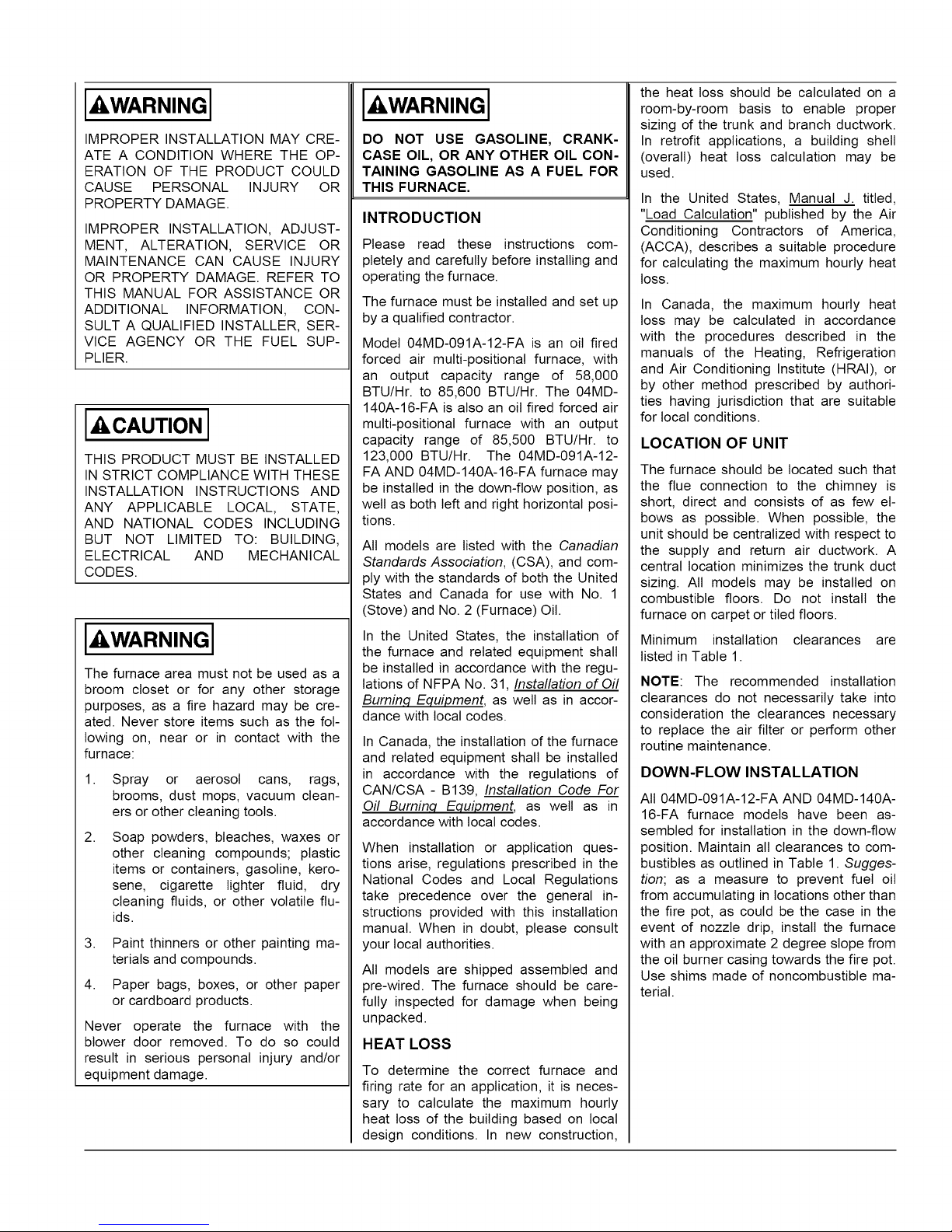
Table 1 : Clearance to Combustibles
Furnace 04MD-091A-12-FA 04MD-140A-16-FA
Location Down flow Horizontal Down flow Horizontal
Top 0 in. 3 in. 0 in. 3 in.
Bottom 0 in. 1 in. 1 in. 1 in.
S/A Plenum 1 in. 1 in. 1 in. 1 in.
Rear 1 in. 1 in. 1 in. 1 in.
Sides 1 in. 1 in. 1 in. 1 in.
Front 10 in. 1 10 in.1 10 in._ 10 in._
Flue Pipe 9 in. 2 9 in. 2 9 in. 2 9 in. 2
Enclosure Closet Closet Closet Closet
24 inches is required for servicing.
218 inches required in the United States.
noncombustible material.
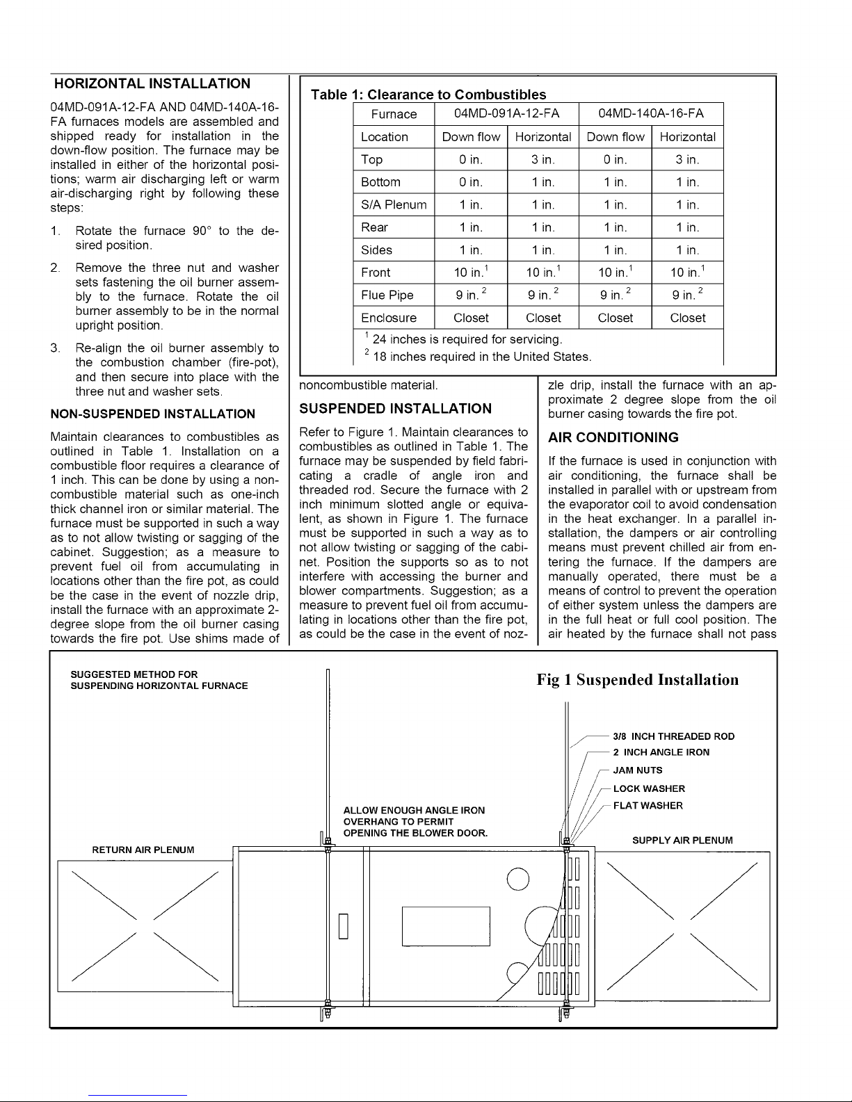
SUSPENDED INSTALLATION
Refer to Figure 1. Maintain clearances to
combustibles as outlined in Table 1. The
furnace may be suspended by field fabri-
cating a cradle of angle iron and
threaded rod. Secure the furnace with 2
inch minimum slotted angle or equiva-
lent, as shown in Figure 1. The furnace
must be supported in such a way as to
not allow twisting or sagging of the cabi-
net. Position the supports so as to not
interfere with accessing the burner and
blower compartments. Suggestion; as a
measure to prevent fuel oil from accumu-
lating in locations other than the fire pot,
as could be the case in the event of noz-
zte drip, install the furnace with an ap-
proximate 2 degree slope from the oil
burner casing towards the fire pot.
AIR CONDITIONING
If the furnace is used in conjunction with
air conditioning, the furnace shall be
installed in parallel with or upstream from
the evaporator coil to avoid condensation
in the heat exchanger. In a parallel in-
stallation, the dampers or air controlling
means must prevent chilled air from en-
tering the furnace. If the dampers are
manually operated, there must be a
means of control to prevent the operation
of either system unless the dampers are
in the full heat or full cool position. The
air heated by the furnace shall not pass
SUGGESTED METHOD FOR
SUSPENDING HORIZONTAL FURNACE
RETURN AIR PLENUM
ALLOW ENOUGH ANGLE IRON
OVERHANG TO PERMIT
OPENING THE BLOWER DOOR.
Fig 1 Suspended Installation
3/8 INCH THREADED ROD
INCH ANGLE IRON
JAM!!!y AIR PLENUM
;= =222
©
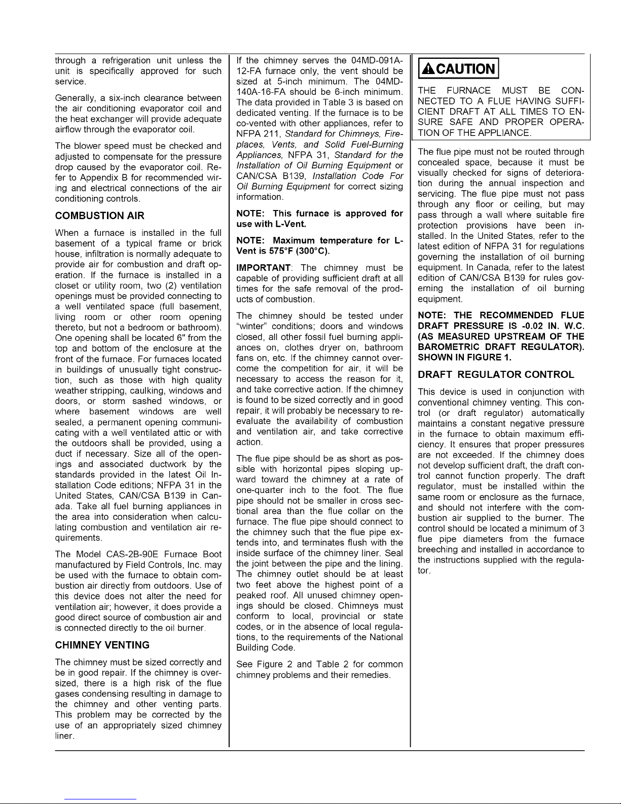
through a refrigeration unit unless the
unit is specifically approved for such
service.
Generally, a six-inch clearance between
the air conditioning evaporator coil and
the heat exchanger wilt provide adequate
airflow through the evaporator coil.
The blower speed must be checked and
adjusted to compensate for the pressure
drop caused by the evaporator coil. Re-
fer to Appendix B for recommended wil-
ing and electrical connections of the air
conditioning controls.
COMBUSTION AIR
When a furnace is installed in the full
basement of a typical frame or brick
house, infiltration is normally adequate to
provide air for combustion and draft op-
eration. If the furnace is installed in a
closet or utility room, two (2) ventilation
openings must be provided connecting to
a well ventilated space (full basement,
living room or other room opening
thereto, but not a bedroom or bathroom).
One opening shall be located 6" from the
top and bottom of the enclosure at the
front of the furnace. For furnaces located
in buildings of unusually tight construc-
tion, such as those with high quality
weather stripping, caulking, windows and
doors, or storm sashed windows, or
where basement windows are well
sealed, a permanent opening communi-
cating with a welt ventilated attic or with
the outdoors shall be provided, using a
duct if necessary. Size all of the open-
ings and associated ductwork by the
standards provided in the latest Oil In-
stallation Code editions; NFPA 31 in the
United States, CAN/CSA B139 in Can-
ada. Take all fuel burning appliances in
the area into consideration when calcu-
lating combustion and ventilation air re-
quirements.
The Model CAS-2B-90E Furnace Boot
manufactured by Field Controls, Inc. may
be used with the furnace to obtain com-
bustion air directly from outdoors. Use of
this device does not alter the need for
ventilation air; however, it does provide a
good direct source of combustion air and
is connected directly to the oil burner.
CHIMNEY VENTING
The chimney must be sized correctly and
be in good repair. If the chimney is ovel-
sized, there is a high risk of the flue
gases condensing resulting in damage to
the chimney and other venting parts.
This problem may be corrected by the
use of an appropriately sized chimney
liner.
If the chimney serves the 04MD-091A-
12-FA furnace only, the vent should be
sized at 5-inch minimum. The 04MD-
140A-16-FA should be 6-inch minimum.
The data provided in Table 3 is based on
dedicated venting. If the furnace is to be
co-vented with other appliances, refer to
NFPA 211, Standard for Chimneys, Fire-
places, Vents, and Solid Fuel-Burning
Appliances, NFPA 31, Standard for the
Installation of Oil Burning Equipment or
CAN/CSA B139, Installation Code For
Oil Burning Equipment for correct sizing
information.
NOTE: This furnace is approved for
use with L-Vent.
NOTE: Maximum temperature for L-
Vent is 575°F (300°C).
IMPORTANT: The chimney must be
capable of providing sufficient draft at all
times for the safe removal of the prod-
ucts of combustion.
The chimney should be tested under
"winter" conditions; doors and windows
closed, all other fossil fuel burning appli-
ances on, clothes dryer on, bathroom
fans on, etc. If the chimney cannot over-
come the competition for air, it wilt be
necessary to access the reason for it,
and take corrective action. If the chimney
is found to be sized correctly and in good
repair, it wilt probably be necessary to re-
evaluate the availability of combustion
and ventilation air, and take corrective
action.
The flue pipe should be as short as pos-
sible with horizontal pipes sloping up-
ward toward the chimney at a rate of
one-quarter inch to the foot. The flue
pipe should not be smaller in cross sec-
tional area than the flue collar on the
furnace. The flue pipe should connect to
the chimney such that the flue pipe ex-
tends into, and terminates flush with the
inside surface of the chimney liner. Seal
the joint between the pipe and the lining.
The chimney outlet should be at least
two feet above the highest point of a
peaked roof. All unused chimney open-
ings should be closed. Chimneys must
conform to local, provincial or state
codes, or in the absence of local regula-
tions, to the requirements of the National
Building Code.
See Figure 2 and Table 2 for common
chimney problems and their remedies.
[_CAUTION [
THE FURNACE MUST BE CON-
NECTED TO A FLUE HAVING SUFFI-
CIENT DRAFT AT ALL TIMES TO EN-
SURE SAFE AND PROPER OPERA-
TION OF THE APPLIANCE.
The flue pipe must not be routed through
concealed space, because it must be
visually checked for signs of deteriora-
tion during the annual inspection and
servicing. The flue pipe must not pass
through any floor or ceiling, but may
pass through a wall where suitable fire
protection provisions have been in-
stalled. In the United States, refer to the
latest edition of NFPA 31 for regulations
governing the installation of oil burning
equipment. In Canada, refer to the latest
edition of CAN/CSA B139 for rules gov-
erning the installation of oil burning
equipment.
NOTE: THE RECOMMENDED FLUE
DRAFT PRESSURE IS -0.02 IN. W.C.
(AS MEASURED UPSTREAM OF THE
BAROMETRIC DRAFT REGULATOR).
SHOWN IN FIGURE 1.
DRAFT REGULATOR CONTROL
This device is used in conjunction with
conventional chimney venting. This con-
trol (or draft regulator) automatically
maintains a constant negative pressure
in the furnace to obtain maximum effi-
ciency. It ensures that proper pressures
are not exceeded. If the chimney does
not develop sufficient draft, the draft con-
trol cannot function properly. The draft
regulator, must be installed within the
same room or enclosure as the furnace,
and should not interfere with the com-
bustion air supplied to the burner. The
control should be located a minimum of 3
flue pipe diameters from the furnace
breeching and installed in accordance to
the instructions supplied with the regula-
tor.
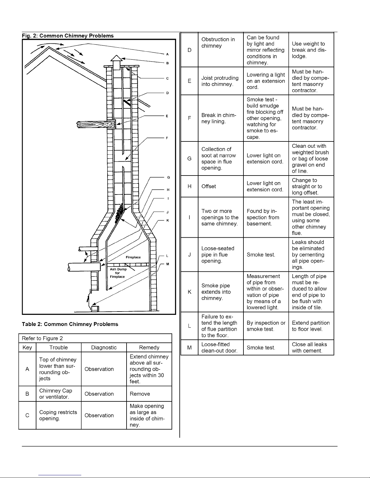
Fig. 2: Common Chimney Problems
Table 2: Common Chimney Problems
Refer to Figure 2
Key Trouble Diagnostic
Top of chimney
lower than sur-
A
rounding ob-
Observation
jects
Chimney Cap
or ventilator.
Coping restricts
opening.
Observation
Observation
Fireplace
for
Extend chimney
above all sur-
rounding ob-
jects within 30
feet.
Remove
Make opening
as large as
inside of chim-
ney.
m H
Remedy
Obstruction in
chimney
A
B
D
Joist protruding
into chimney.
Can be found
by light and
mirror reflecting
conditions in
chimney.
Lowering a light
on an extension
cord.
Use weight to
break and dis-
lodge.
Must be han-
dled by compe-
tent masonry
contractor.
Smoke test -
Break in chim-
ney lining.
build smudge
fire blocking off
other opening,
watching for
smoke to es-
Must be han-
dled by compe-
tent masonry
contractor.
cape.
Collection of
soot at narrow
G
space in flue
Lower light on
extension cord.
opening.
G
H
Offset
I
J
K
Two or more
openings to the
same chimney.
Lower light on
extension cord.
Found by in-
spection from
basement.
Clean out with
weighted brush
or bag of loose
gravel on end
of line.
Change to
straight or to
long offset.
The least im-
portant opening
must be closed,
using some
other chimney
flue.
Leaks should
Loose-seated
L
M
pipe in flue
opening.
Smoke test.
Measurement
Smoke pipe
extends into
chimney.
of pipe from
within or obser-
vation of pipe
by means of a
lowered light.
be eliminated
by cementing
all pipe open-
ings.
Length of pipe
must be re-
duced to allow
end of pipe to
be flush with
inside of tile.
Failure to ex-
tend the length
of flue partition
By inspection or
smoke test.
Extend partition
to floor level.
to the floor.
Loose-fitted Close all leaks
M Smoke test.
clean-out door. with cement.
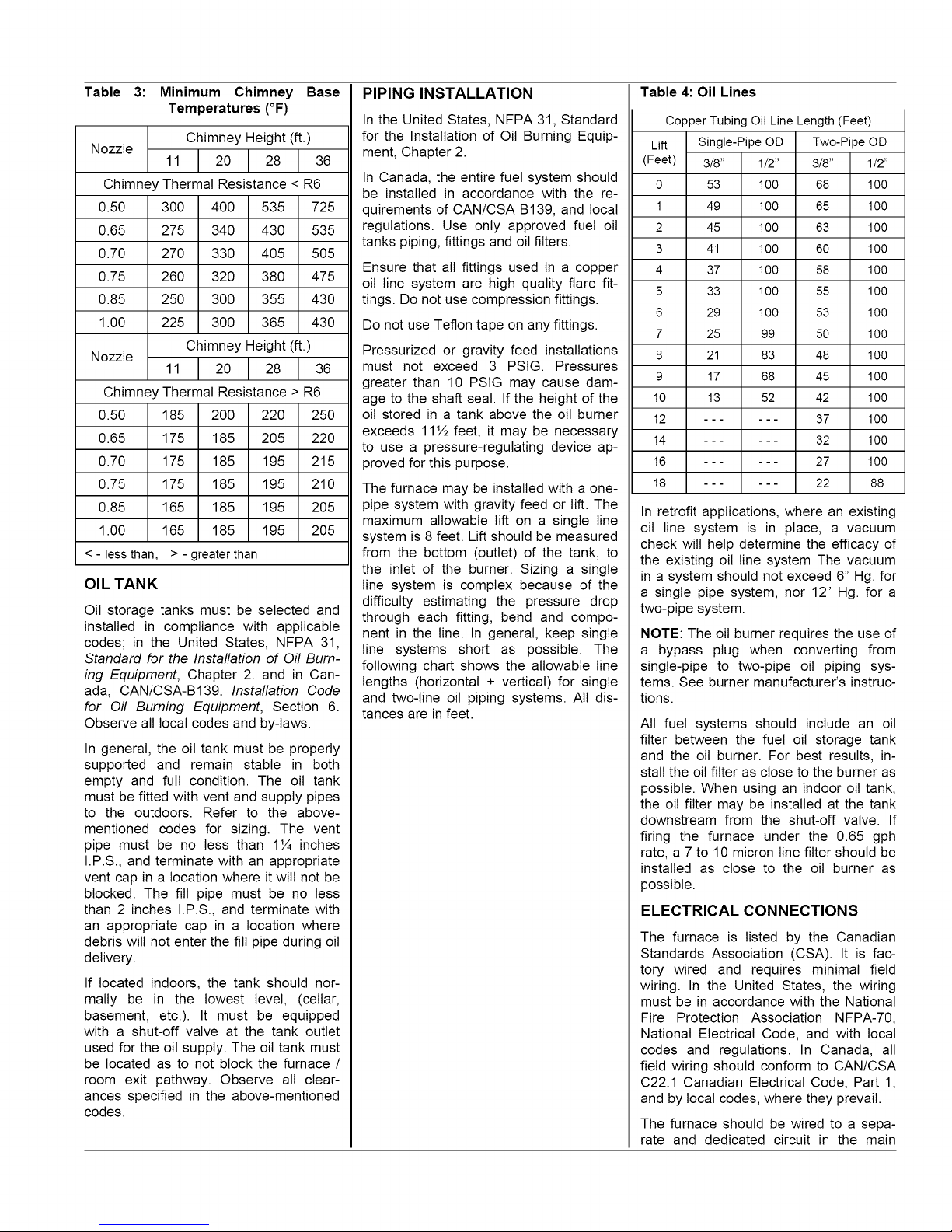
Table 3: Minimum Chimney Base
Temperatures (°F)
Chimney Height (ft.)
Nozzle
Chimney Thermal Resistance < R6
0.50 300 1400 535 725
0.65 275 1340 430 535
0.70 270 1330 405 505
0.75 260 1320 380 475
0.85 250 1300 355 430
1.00 225 1300 365 430
Chimney Height (ft.)
Nozzle _
Chimney Thermal Resistance > R6
0.50
0.65
0.70
0.75
0.85
1.00
< - less than,
185 200 220 250
175 185 205 220
175 185 195 215
175 185 195 210
165 185 195 205
165 185 195 205
>-greaterthan
OIL TANK
Oil storage tanks must be selected and
installed in compliance with applicable
codes; in the United States, NFPA 31,
Standard for the Installation of Off Burn-
ing Equipment, Chapter 2. and in Can-
ada, CAN/CSA-B139, Installation Code
for Oil Burning Equipment, Section 6.
Observe all local codes and by-laws.
In general, the oil tank must be properly
supported and remain stable in both
empty and full condition. The oil tank
must be fitted with vent and supply pipes
to the outdoors. Refer to the above-
mentioned codes for sizing. The vent
pipe must be no tess than 1¼ inches
I.P.S., and terminate with an appropriate
vent cap in a location where it will not be
blocked. The fill pipe must be no less
than 2 inches I.P.S., and terminate with
an appropriate cap in a location where
debris will not enter the fill pipe during oil
delivery.
If located indoors, the tank should nor-
mally be in the lowest level, (cellar,
basement, etc.). It must be equipped
with a shut-off valve at the tank outlet
used for the oil supply. The oil tank must
be located as to not block the furnace /
room exit pathway. Observe all clear-
ances specified in the above-mentioned
codes.
PIPING INSTALLATION
In the United States, NFPA 31, Standard
for the Installation of Oil Burning Equip-
ment, Chapter 2.
In Canada, the entire fuel system should
be installed in accordance with the re-
quirements of CAN/CSA B139, and local
regulations. Use only approved fuel oil
tanks piping, fittings and oil filters.
Ensure that all fittings used in a copper
oil line system are high quality flare fit-
tings. Do not use compression fittings.
Do not use Teflon tape on any fittings.
Pressurized or gravity feed installations
must not exceed 3 PSIG. Pressures
greater than 10 PSlG may cause dam-
age to the shaft seal. If the height of the
oil stored in a tank above the oil burner
exceeds 11½ feet, it may be necessary
to use a pressure-regulating device ap-
proved for this purpose.
The furnace may be installed with a one-
pipe system with gravity feed or lift. The
maximum allowable lift on a single line
system is 8 feet. Lift should be measured
from the bottom (outlet) of the tank, to
the inlet of the burner. Sizing a single
line system is complex because of the
difficulty estimating the pressure drop
through each fitting, bend and compo-
nent in the line. In general, keep single
line systems short as possible. The
following chart shows the allowable line
lengths (horizontal + vertical) for single
and two-line oil piping systems. All dis-
tances are infeet.
Table 4: Oil Lines
Copper Tubing Oil Line Length (Feet)
Single-Pipe OD Two-Pipe OD
In retrofit applications, where an existing
oil line system is in place, a vacuum
check wilt help determine the efficacy of
the existing oil line system The vacuum
in a system should not exceed 6" Hg. for
a single pipe system, nor 12" Hg. for a
two-pipe system.
NOTE: The oil burner requires the use of
a bypass plug when converting from
single-pipe to two-pipe oil piping sys-
tems. See burner manufacturer's instruc-
tions.
All fuel systems should include an oil
filter between the fuel oil storage tank
and the oil burner. For best results, in-
stall the oil filter as close to the burner as
possible. When using an indoor oil tank,
the oil filter may be installed at the tank
downstream from the shut-off valve. If
firing the furnace under the 0.65 gph
rate, a 7 to 10 micron line filter should be
installed as close to the oil burner as
possible.
ELECTRICAL CONNECTIONS
The furnace is listed by the Canadian
Standards Association (CSA). It is fac-
tory wired and requires minimal field
wiring. In the United States, the wiring
must be in accordance with the National
Fire Protection Association NFPA-70,
National Electrical Code, and with local
codes and regulations. In Canada, all
field wiring should conform to CAN/CSA
C22.1 Canadian Electrical Code, Part 1,
and by local codes, where they prevail.
The furnace should be wired to a sepa-
rate and dedicated circuit in the main
electricalpanel;however,accessory
equipmentsuchaselectronicairclean-
ersandhumidifiersmaybeincludedon
thefurnacecircuit.Althougha suitably
locatedcircuitbreakercanbeusedasa
serviceswitch,aseparateserviceswitch
isadvisable.Theserviceswitchisnec-
essaryif reachingthecircuitbreaker
involvesbecomingclosetothefurnace,
orif thefurnaceislocatedbetweenthe
circuitbreakerandthemeansofentryto
thefurnaceroom.Thefurnaceswitch
(serviceswitch)should be clearly
marked,installedinaneasilyaccessible
areabetweenthefurnaceandfurnace
roomentry,andbe locatedin sucha
mannerto reducethelikelihoodthatit
wouldbemistakenasa lightswitchor
similardevice.
Thepowerrequirementsforallmodels:
120VAC,1®,60Hz.,12A.
Accessoriesrequiring120VACpower
sourcessuchaselectronicaircleaners
and humidifiertransformersmaybe
poweredfromtheST9103EFT.Donot
usethedirectdrivemotorconnectionsas
apowersource,sincethereisahighrisk
ofdamagingtheaccessoriesbyexpo-
sureto highvoltagefromthe auto-
generatingwindingsof thedirectdrive
motor.
Thermostatwiringconnectionsandair
conditioningcontactorlowvoltagecon-
nectionsareshownin thewiringdia-
grams.Somemicro-electronicthermo-
statsrequireadditionalcontrolsandwir-
ing.Referto thethermostatmanufac-
turer'sinstructions.
Thethermostatshouldbe locatedap-
proximately5feetabovethefloor,onan
insidewaltwherethereisgoodnatural
aircirculation,andwherethethermostat
wiltbeexposedto averageroomtem-
peratures.Avoidlocationswherethe
thermostatwiltbeexposedtocolddrafts,
heatfromnearbylampsandappliances,
exposureto sunlight,heatfrominside
waltstacks,etc.
Normalheatanticipatorsetting:0.1A.
Formorepreciseadjustment,theheat
anticipatormaybeadjustedtotheam-
peragedrawoftheheatingcontrolcircuit
asmeasuredbetweenthe"R"and"W"
terminalsof thethermostat.Toreduce
theriskofdamagingtheheatanticipator,
donotmeasurecircuitwithoutfirstre-
movingoneof thetwowiresfirst.To
determinetheheatingcircuitamperage
draw:
1. Disconnectoneof the"R"or "W"
wiresfromthethermostatterminal.
2. Connectan ammeterbetweenthe
wireandthethermostatterminalto
whichitwasattached.
3.
Note the amperage reading when
the heating contacts are closed.
(System switch must be on "HEAT"if
SOequipped.
4.
Re-connect the thermostat wire. If
the thermostat is serving a combina-
tion heating and air conditioning sys-
tem, pay particular attention to po-
larity.
5.
When the thermostat is reconnected
and re-plumbed, adjust the heat an-
ticipator setting to match the ob-
served amperage reading.
FAN TIMER BOARD AND LIMIT
CONTROL
The Electronic Fan Timer integrates con-
trol of all burner and circulator fan opera-
tions. This control is the central wiring
point for most of the electrical compo-
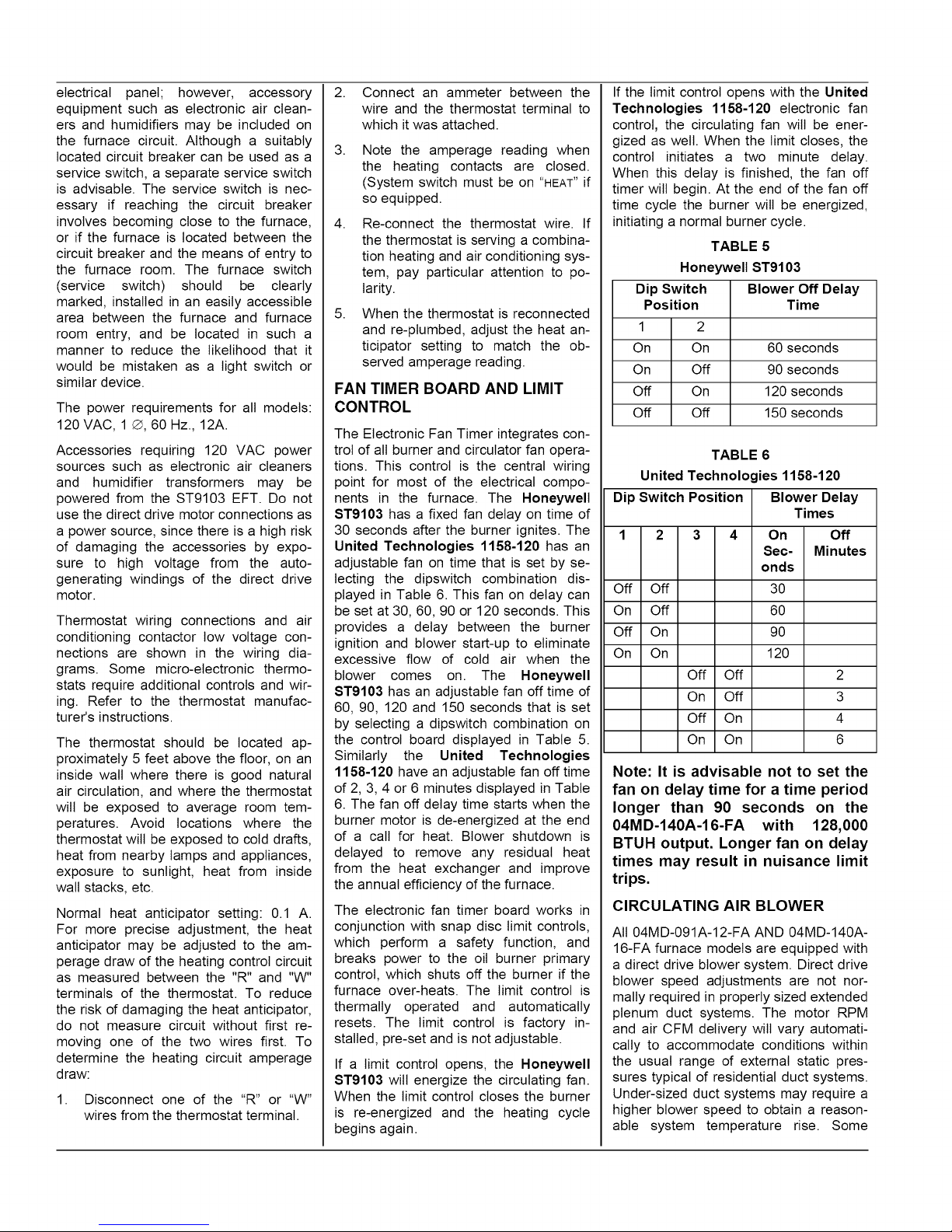
nents in the furnace. The Honeywell
ST9103 has a fixed fan delay on time of
30 seconds after the burner ignites. The
United Technologies 1158-120 has an
adjustable fan on time that is set by se-
lecting the dipswitch combination dis-
played in Table 6. This fan on delay can
be set at 30, 60, 90 or 120 seconds. This
provides a delay between the burner
ignition and blower start-up to eliminate
excessive flow of cold air when the
blower comes on. The Honeywell
ST9103 has an adjustable fan off time of
60, 90, 120 and 150 seconds that is set
by selecting a dipswitch combination on
the control board displayed in Table 5.
Similarly the United Technologies
1158-120 have an adjustable fan off time
of 2, 3, 4 or 6 minutes displayed in Table
6. The fan off delay time starts when the
burner motor is de-energized at the end
of a call for heat. Blower shutdown is
delayed to remove any residual heat
from the heat exchanger and improve
the annual efficiency of the furnace.
The electronic fan timer board works in
conjunction with snap disc limit controls,
which perform a safety function, and
breaks power to the oil burner primary
control, which shuts off the burner if the
furnace over-heats. The limit control is
thermally operated and automatically
resets. The limit control is factory in-
stalled, pre-set and is not adjustable.
If a limit control opens, the Honeywell
ST9103 wilt energize the circulating fan.
When the limit control closes the burner
is re-energized and the heating cycle
begins again.
If the limit control opens with the United
Technologies 1158-120 electronic fan
control, the circulating fan will be ener-
gized as welt. When the limit closes, the
control initiates a two minute delay.
When this delay is finished, the fan off
timer will begin. At the end of the fan off
time cycle the burner will be energized,
initiating a normal burner cycle.
TABLE 5
Honeywell ST9103
Dip Switch Blower Off Delay
Position Time
1_ 60 seconds
On I Off
off I On
Off I Off
TABLE 6
United Technologies 1158-120
Dip Switch Position
1 2 3 4
Dff Off
Dn Off
Dff On
Dn On
Off Off
On Off
Off On
On On
Note: It is advisable not to set the
fan on delay time for a time period
longer than 90 seconds on the
04MD-140A-16-FA with 128,000
BTUH output. Longer fan on delay
times may result in nuisance limit
trips.
CIRCULATING AIR BLOWER
All 04MD-091A-12-FA AND 04MD-140A-
16-FA furnace models are equipped with
a direct drive blower system. Direct drive
blower speed adjustments are not nor-
mally required in properly sized extended
31enum duct systems. The motor RPM
and air CFM delivery will vary automati-
cally to accommodate conditions within
the usual range of external static pres-
sures typical of residential duct systems.
Under-sized duct systems may require a
higher blower speed to obtain a reason-
able system temperature rise. Some
90 seconds
120 seconds
150 seconds
Blower Delay
Times
On I
Sec-I
ondsl
Minutes
3o I
6o I
go I
120 I
i
i
i
i
Off
2
3
4
6
olderductsystemswerenotdesignedto
providestaticpressure.Theytypically
featurespecialreducingfittingsateach
branchrunandtackblockendsonthe
trunkducts.Thesesystemsmayrequire
modificationtoprovidesomeresistance
totheairflowtopreventover-ampingof
thedirectdriveblowermotor.Selectinga
lowerblowerspeedmaycorrectthis
problem.
Directdriveblowerspeedsareadjusted
bychangingthe"hot"wirestothemotor
windingconnections.Pleasereferto
wiringdiagraminAppendixBorthewir-
ingdiagramlabelaffixedtothefurnace.
THE NEUTRAL WIRE (normally the
white wire) IS NEVER MOVED TO AD-
JUST THE BLOWER SPEED,
I_CAUTION ]
DO NOT CONNECT POWER LEADS
BETWEEN MOTOR SPEEDS, THE
NEUTRAL WIRE MUST ALWAYS BE
CONNECTED TO THE MOTOR'S DES-
IGNATED NEUTRAL TERMINAL,
It is possible and acceptable to use a
single blower speed for both heating and
cooling modes. The simplest method to
connect the wiring from both modes is to
use a "piggy-back connector" accommo-
dating both wires on a single motor tap.
It is also acceptable to connect the se-
lected motor speed with a pigtail joined
to both heating and cooling speed wires
with a wire nut. As a safety precaution
against accidental disconnection of the
wires by vibration, it is advisable to se-
cure the wire nut and wires with a few
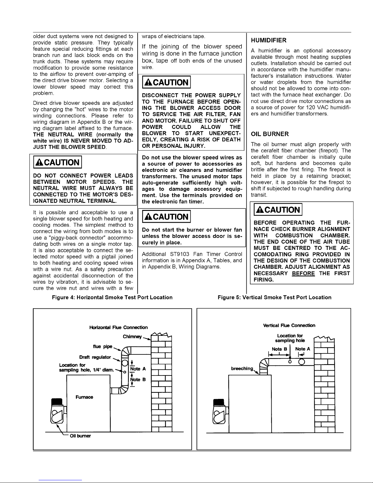
Figure 4: Horizontal Smoke Test Port Location Figure 5: Vertical Smoke Test Port Location
wraps of electricians tape.
If the joining of the blower speed
wiring is done in the furnace junction
box, tape off both ends of the unused
wire.
IACAUTION I
DISCONNECT THE POWER SUPPLY
TO THE FURNACE BEFORE OPEN-
ING THE BLOWER ACCESS DOOR
TO SERVICE THE AIR FILTER, FAN
AND MOTOR, FAILURE TO SHUT OFF
POWER COULD ALLOW THE
BLOWER TO START UNEXPECT-
EDLY, CREATING A RISK OF DEATH
OR PERSONAL INJURY,
Do not use the blower speed wires as
a source of power to accessories as
electronic air cleaners and humidifier
transformers. The unused motor taps
auto-generate sufficiently high volt-
ages to damage accessory equip-
ment. Use the terminals provided on
the electronic fan timer.
IACAUTION I
Do not start the burner or blower fan
unless the blower access door is se-
curely in place,
Additional ST9103 Fan Timer Control
information is in Appendix A, Tables, and
in Appendix B, Wiring Diagrams.
HUMIDIFIER
A humidifier is an optional accessory
available through most heating supplies
outlets. Installation should be carried out
in accordance with the humidifier manu-
facturer's installation instructions. Water
or water droplets from the humidifier
should not be allowed to come into con-
tact with the furnace heat exchanger. Do
not use direct drive motor connections as
a source of power for 120 VAC humidifi-
ers and humidifier transformers.
OIL BURNER
The oil burner must align properly with
the cerafelt fiber chamber (firepot). The
cerafelt fiber chamber is initially quite
soft, but hardens and becomes quite
brittle after the first firing. The firepot is
held in place by a retaining bracket;
however, it is possible for the firepot to
shift if subjected to rough handling during
transit.
IACAUTION I
BEFORE OPERATING THE FUR-
NACE CHECK BURNER ALIGNMENT
WITH COMBUSTION CHAMBER,
THE END CONE OF THE AIR TUBE
MUST BE CENTRED TO THE AC-
COMODATING RING PROVIDED IN
THE DESIGN OF THE COMBUSTION
CHAMBER, ADJUST ALIGNMENT AS
NECESSARY BEFORE THE FIRST
FIRING,
Horizontal Flue Connection
Chimney
flue pipe
Draft regulator
Location for
sampling hole, 1/4" diam. -_
[]
Fumace
Vertical Flue Connection
m
• i
m
breeching_ ' 0
m
Location for
samplinghole
_ Note A
| .
m
m
m
OIL BURNER NOZZLES
04MD-091A-12-FA AND 04MD-140A-16-
FA furnaces are certified for multiple
firing rates, ranging from approximately
56,000 to 85,600 BTU/hr. on the 04MD-
091A-12-FA and 85,500 to 123,000
BTU/Hr. on the 04MD-140A-16-FA By
changing the oil burner nozzle within the
specific model range, and temperature
rise, the furnace may be fired at an ideal
rate for a wide range of structures.
BURNER ELECTRODES
Correct positioning of the electrode tips
with respect to each other, to the fuel oil
nozzle, and to the rest of the burners is
essential for smooth light ups and proper
operation. The electrode tips should be
adjusted to a gap of 5/32", 1/16" ahead
of the nozzle, 5/16" above the centertine
of the nozzle. The "Z" dimension (front
edge of the burner head to the front face
of the nozzle is 1-1/8 inches.
Electrode positioning should be checked
before the first firing of the furnace.
The electrode porcelains should be free
of cracks, the electrode tips should be
tapered and free of burrs, and the con-
tact rods must be clean and be in firm
contact with the ignition transformer con-
tact springs. The electrodes must not
come into contact with the burner head.
OILBURNERSET-UP
The burner air supply is adjusted to
maintain the fuel to air ratio to obtain
ideal combustion conditions. A lack of air
causes "soft" and "sooty" flames, result-
ing in soot build-up throughout the heat
exchanger passages. Excess combus-
tion air causes a bright roaring fire and
high stack temperatures resulting in poor
fuel efficiency.
PREPARATIONS:
Drill a ¼" test port in the venting, ideally
at least 2 flue pipe diameters away from
the furnace breeching, if venting horizon-
tally from the furnace, or from the flue
pipe elbow if venting vertically before
reaching the furnace. (See Figures 4 and
5).
The test port will allow flue gas samples
to be taken and stack temperatures to be
measured.
Before starting the burner, check the
burner alignment with the combustion
chamber (fire pot), check that the correct
nozzle is tightened into place, and that
the burner electrodes are properly posi-
tioned.
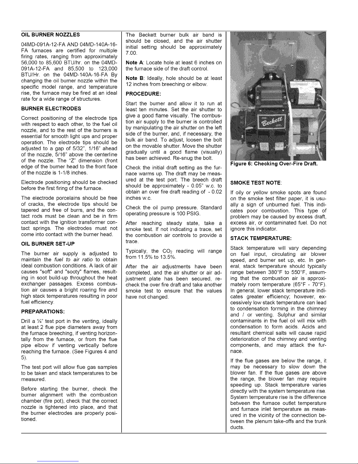
The Beckett burner bulk air band is
should be closed, and the air shutter
initial setting should be approximately
7.00.
Note A: Locate hole at least 6 inches on
the furnace side of the draft control.
Note B: Ideally, hole should be at least
12 inches from breeching or elbow.
PROCEDURE:
Start the burner and allow it to run at
least ten minutes. Set the air shutter to
give a good flame visually. The combus-
tion air supply to the burner is controlled
by manipulating the air shutter on the left
side of the burner, and, if necessary, the
bulk air band. To adjust, loosen the bolt
on the movable shutter. Move the shutter
gradually until a good flame (visually)
has been achieved. Re-snug the bolt.
Check the initial draft setting as the fur-
nace warms up. The draft may be meas-
ured at the test port. The breech draft
should be approximately - 0.05" w.c. to
obtain an over fire draft reading of - 0.02
inches w.c.
Check the oil pump pressure. Standard
operating pressure is 100 PSIG.
After reaching steady state, take a
smoke test. If not indicating a trace, set
the combustion air controls to provide a
trace.
Typically, the 002 reading will range
from 11.5% to 13.5%.
After the air adjustments have been
completed, and the air shutter or air ad-
justment plate has been secured, re-
check the over fire draft and take another
smoke test to ensure that the values
have not changed.
Figure 6: Checking Over-Fire Draft.
SMOKE TEST NOTE:
If oily or yellow smoke spots are found
on the smoke test filter paper, it is usu-
ally a sign of unburned fuel. This indi-
cates poor combustion. This type of
problem may be caused by excess draft,
excess air, or contaminated fuel. Do not
ignore this indicator.
STACK TEMPERATURE:
Stack temperature wilt vary depending
on fuel input, circulating air blower
speed, and burner set up, etc. In gen-
eral, stack temperature should typically
range between 380°F to 550°F, assum-
ing that the combustion air is approxi-
mately room temperature (65°F - 70°F).
In general, lower stack temperature indi-
cates greater efficiency; however, ex-
cessively low stack temperature can lead
to condensation forming in the chimney
and / or venting. Sulphur and similar
contaminants in the fuel oil will mix with
condensation to form acids. Acids and
resultant chemical salts wilt cause rapid
deterioration of the chimney and venting
components, and may attack the fur-
nace.
If the flue gases are below the range, it
may be necessary to slow down the
blower fan. If the flue gases are above
the range, the blower fan may require
speeding up. Stack temperature varies
directly with the system temperature rise.
System temperature rise is the difference
between the furnace outlet temperature
and furnace inlet temperature as meas-
ured in the vicinity of the connection be-
tween the plenum take-offs and the trunk
ducts.
If theventingfromthefurnaceto the
chimneyislong,orexposedtocoldam-
bienttemperatures,itmaybenecessary
touseL-Ventastheventconnectorto
reducestacktemperaturetosstoprevent
condensation.Theventingshouldbe
inspectedannuallyto ensurethatit is
intact.
FURNACE INSTALLATION SET-
UP
The furnace must be set up as the final
step in the installation.
A) The oil burner must be set up follow-
ing the procedures outlined above.
B) The 04MD-091A-12-FA models
should operate within a temperature rise
of 45°F to 75°F. The 04MD-140A-16-FA
temperature rise range should be 50 to
80°F. To determine the temperature rise,
measure the supply air and return air
temperatures when the furnace has
reached steady state conditions. This is
the point at which the supply air tem-
perature stops increasing relative to the
return air temperature. The furnace may
have to run 10 to 15 minutes to reach
steady state conditions. The measure-
ments may be made with duct ther-
mometers or thermocouples used in con-
junction with multi-meters with tempera-
ture measurement capabilities.
The return air should be measured at a
point where the thermometer will be well
within the air stream near the furnace
return air inlet. Actual location is not par-
ticularly critical; however, avoid locations
where the temperature readings could be
affected by humidifier bypass ducts, the
inside radius of elbows, etc.
The supply air temperature should be
measured at a point where the ther-
mometer wilt be welt within the air stream
near the furnace supply air outlet. Usu-
ally, the side mid-point of the supply air
plenum take-off is ideal, providing it is
out of the line of sight to the heat ex-
changer. If the thermometer is within the
line of sight of the heat exchanger, the
supply air readings may be skewed by
radiant heat from the heat exchanger. If
the plenum take-off is unsuitable, the
supply air temperature may be measured
within the first 18 inches of the first seg-
ment of supply air trunk duct.
If the temperature rise is outside the rec-
ommended range, it may be adjusted on
direct drive equipped units by selecting
alternate circulation fan motor speeds. If
the temperature rise is too high, speed
the fan up. If the temperature rise is too
low, slow the fan down.
C) Keep in mind that the stack tem-
perature varies directly with the tempera-
ture rise. The higher the temperature
rise, the higher the stack temperature wilt
be, resulting in lower efficiency. The
lower the temperature rise, the lower the
stack temperature will be, which, in some
cases, may allow condensation to form
in the chimney and other vent parts.
D) Test the high limit control to ensure
that it is operating correctly. This may be
done by temporarily removing the circu-
lator fan heating wire or neutral wire.
Turn off electrical power to the furnace
before working with the motor wires. Be
sure to protect any removed wires from
shorting out on metal furnace parts. Ifthe
high limit test is successful, shut off the
electrical power to the furnace, restore
the proper motor wiring. Finally, restore
power to the furnace.
E) Operate the furnace through a
minimum of three full heating cycles.
During this time, check for fuel oil leaks,
gross air leakage from the supply air
ductwork, unusual noises originating
anywhere within the heating system
which may cause some concern or an-
noyance to the home owner, etc.
F) Be sure that the homeowner is fa-
miliar with the furnace. The homeowner
should be aware of the location of elec-
trical circuit breaker or fuse, the location
of any electrical switches controlling the
furnace, the location of the oil tank shut-
off valve and how to operate the valve.
The homeowner should be informed
where the oil tank gauge is located and
how to read it.
It would be beneficial to review safety
issues with the home owner, such as the
danger of storing combustibles too close
to the furnace, hanging anything on the
furnace vent pipe, and especially the
dangers of indiscriminately pressing the
burner reset button.
IMPORTANT: Be sure that the home
owner knows where the burner reset
switch is located, and is aware that the
reset switch is not to be activated more
than once without a thorough took for the
cause of the problem, (tack of fuel, etc.).
Be sure that the homeowner knows
when to quit trying to start the furnace
during these conditions and who to call
for emergency service.
MAINTENANCE AND SERVICE
A: Routine Maintenance By Home
Owner
Other than remembering to arrange for
the annual professional servicing of the
furnace by the service or installation con-
tractor, the most important routine ser-
vice performed by the homeowner is to
maintain the air filter or filters. A dirty
filter can cause the furnace to over-heat,
fail to maintain indoor temperature during
cold weather, increase fuel consumption
and cause component failure.
The furnace filter(s) should be inspected,
cleaned or replaced monthly. The fur-
nace is factory equipped with a semi-
permanent type filter. If the filter is dam-
aged, replace with filters of the same
size and type.
During the routine service, inspect the
general condition of the furnace watching
for signs of oil leaks in the vicinity of the
oil burner, soot forming on any external
part of the furnace, soot forming around
the joints in the vent pipe, etc. If any of
these conditions are present, please
advise your service or installation con-
tractor.
B: Annual Service By Contractor
[_CAUTION [
THE COMBUSTION CHAMBER (FIRE-
POT) IS FRAGILE. USE CARE WHEN
INSPECTING AND CLEANING THIS
AREA.
The heat exchanger should be inspected
periodically and cleaned if necessary. If
cleaning is necessary, SHUT OFF
POWER TO THE FURNACE and re-
move the burner. Using a stiff brush with
a wire handle, brush off scale and soot
from inside the drum and flue pipe. To
clean the radiator, remove the round
cover or covers on the inner radiator
access pipes located on the front panel
between the oil burner and the flue pipe.
Rear breech models have a single front
cleanout and front breech models have
two front cleanouts.
A wire brush can be used to loosen dirt
and debris on the inside surfaces of the
radiator. Clean out all accumulated dirt,
soot and debris with a wire handled
brush and an industrial vacuum cleaner.
Replace the clean-out covers.
Most circulating fan motors are perma-
nently lubricated by the motor manufac-
turer. These motors wilt have no oil
ports. If the blower motor does contain
oil ports, under normal operating condi-
tions it wilt not require oiling for the first
two years. Oil sparingly; a few drops in
each oil port with SAE 20 non-detergent
oil. Oiling is most easily done with a
"tele-spout" oiler. This oiler has a long
 Loading...