

Page 1
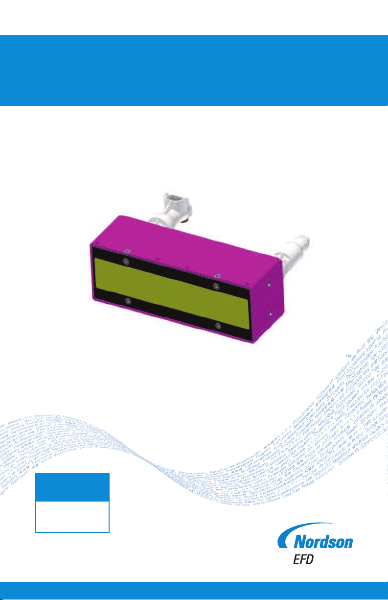
Operating Manual
BlueCure FL
Please read this user manual carefully before initial operation.
IMPORTANT!
Save this Sheet.
Forward to
Maintenance or
Tool Crib Supervisors
Electronic pdf files of
EFD manuals are also available
at www.nordsonefd.com
Page 2

2
Page 3

Contents
1. Safety Instructions ............................................................................................4-7
2. General Information ..........................................................................................8-9
2.1 Pollution Limitations (RoHS) ..........................................................................8
2.2 Chemicals Directive (REACH) ........................................................................8
2.3 Product Recycling (WEEE)..............................................................................8
2.4 Standards and Regulations ............................................................................8
2.5 Unpacking and Inspection..............................................................................9
3. Functionality..........................................................................................................9
4. Technical Specifications ....................................................................................10
5. Installation ....................................................................................................11-16
5.1 SPS Connection ......................................................................................12-13
5.2 Power Supply Connection ............................................................................14
5.3 Possible Connection Scenarios ..............................................................15-16
6. On/Off Control ....................................................................................................16
7. Intensity of the Radiation ....................................................................................17
8. Maintenance ......................................................................................................18
9. Accessories ........................................................................................................18
10. Troubleshooting ..................................................................................................19
A. Appendix ..........................................................................................................20
A.1 Drawing of the BLUE CURE FL-8.0W-125X20-WC-395..............................20
Service Address ........................................................................................Back Cover
Warranty......................................................................................Back Cover
3
Page 4
1. Safety Instructions
Prior to initial operation of the device, it is necessary to follow the operating and
safety instructions. Identical to the standard ANSI Z535.4, the symbols used below
are defined in the standard ISO 3864-2 and represent various warning levels.
Safety symbols – warning against injury
hazards.
DANGER: This symbol indicates a direct
hazard to the life and health of persons!
WARNING: This symbol indicates a potential
hazard to the life and health of persons.
CAUTION: This symbol indicates a potentially
dangerous situation.
The BlueCure LED lamps are equipped with various protection devices, which
comply with international safety standards, in order to ensure the safe use of the
device.
CAUTION!
Attention: Never operate the device while open or damaged or with loose or
missing protection devices.
4
Page 5
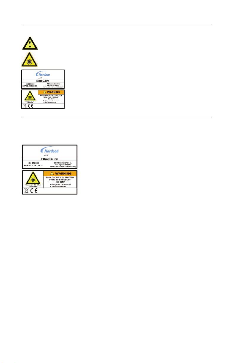
Symbol Safety Instructions
CAUTION
- Read the precautions in the instructions
UV-LIGHT
- Read the precautions in the instructions
CAUTION
- Hazardous UV LED rays
- Use only with shield
- Protect your eyes and skin from the UV rays
Safety instructions labeling on the
BlueCure lamps
The BlueCure lamps are high-intensity UV LED emitting devices for industrial
applications. To achieve short hardening times of the UV hardened materials,
intense UV radiation is necessary.
The standard CEI/IEC 62471 describes the photobiological safety standards for
lamps and LED devices. The actual classification is based on the purpose for
which the device is used. The operating personnel can ensure safe use of the
product through appropriate safety devices and shields that prevent direct eye
contact with the UV radiation.
5
Page 6

Classification of hazards:
The classification describes the potential risks that could occur depending on the
purpose of the application and the length of irradiation. The risks must be
assessed and classified depending on the use of the UV LED light source.
The measurement distance for the classification of hazards is set at 200 mm
according to IEC 62471.
The risks groups defined in IEC 62471:
Risk-free means that, based on this standard, there is no health hazard through
irradiation.
Risk Group 1 – Low risk
Does not pose an irradiation hazard under normal performance and use.
Risk Group 2 – Medium risk
No hazard based on the natural human reaction to a very intense glare or
generation of heat.
Risk Group 3 – High risk
Can be hazardous even in the case of brief exposure to irradiation.
CAUTION!
Attention: The BlueCure lamp emits UV and brief visible light with an intense glare.
Never look at the UV light source without UV protective glasses.
Spectral distribution
6
Page 7

BlueCure lamps are classified as a risk group 3 in accordance with IEC 62471 when
in the vicinity and when looking directly at the source of the radiation. When
integrating the source of radiation into a production system, the risk must generally
be ranked as low to medium if the appropriate distances from the user are ensured
or risk-free in the case of appropriately specified integration schemes.
Looking directly at the light source is dangerous, therefore, it is imperative to wear
safety glasses, e.g. UVEX SCT orange lenses.
The BlueCure lamps are classified as class 3B LEDs in accordance with the
international standard IEC 60825-1:2001. Contrary to laser devices, there is NO
requirement to register devices of this type with a professional association or trade
control. Hiring a laser protection commissioner in the company is NOT necessary.
Primarily organizational and technical protective measures have to be met in areas
in which class 3B LED devices are operated. If this is not possible, appropriate eye
protection devices, protective clothing or protective gloves must be provided for
work in this area within a distance <1.5 meters from the light source in order to
protect eyes and skin. Eye protection must be provided for work in the area within
a distance of 1.5 to 3 meters from the point of the LED where light is emitted. Skin
protection measures are no longer necessary in this case due to the extremely low
intensity of the radiation.
The maximum permissible value for the UV exposition is 83 J/cm2 for a wavelength
of 395 nm.
The described lamps are operational resources for use in industrial facilities. Those
responsible for the safety of the systems must therefore ensure that
• Work on or in the proximity of the BlueCure lamps is conducted only by
sufficiently qualified personnel.
• These persons already have access to the user manual and other product
documentation, etc. and are required to comply with these documents
consistently when executing the respective operations.
CAUTION!
Note: Qualified personnel are persons who, due to their training, experience and
instruction, as well as their knowledge of relevant standards, provisions,
accident prevention regulations and operating conditions, have been
authorized by the person responsible for the safety of the system to perform
the required tasks and, in the process, can identify and prevent potential
risks (definitions for specialists according to VDE 105 or ICE 364).
7
Page 8

2. General Information
2.1 Pollution Limitations (RoHS)
According to our knowledge and the information made available to us, the BlueCure
lamps do not contain materials, for which there are limitations according to RoHS
Directives, above the following specified limits related to the respectively used
homogenous material:
• Lead (Pb) < 0.1 weight %
• Mercury (Hg) < 0.1 weight %
• Chromium-VI (Cr VI) < 0.1 weight %
• Poly brominated biphenyls (PBB) or poly brominated biphenyl ethers (PBDE) < 0.1
weight %
• Cadmium (Cd) < 0.1 weight %
2.2 Chemicals Directive (REACH)
Nordson EFD ensures that the BlueCure products are not subject to the EU Guidelines
of the Chemicals Directive (REACH).
Furthermore, with regard to the planned candidate list of substances of very high
concern (SVHC) – issued on October 10, 2008 – Nordson EFD declares that, to the
best of our knowledge, the BlueCure products do not contain SVHC of more than
0.1% of the weight of the device.
2.3 Product Recycling (WEEE)
The product may not be disposed of as normal waste; rather it must be
recycled.
The BlueCure lamps must be returned to Nordson EFD for disposal or recycling.
2.4 Standards and Regulations
The BlueCure lamp device conforms to the following harmonized standards and
regulations:
• Low Voltage Directive 73 / 23 / EEC as amended by 93 / 68 / EEC
• IEC 60825 -1 (2001)
• IEC 61010 -1 (2001)
• RoHS
• 89/336/EMC; as amended by 92/31/EEC
93/68/EEC
98/13/EEC
8
Page 9

2.5 Unpacking and Inspection
After removal from the packaging, please inspect the delivery for completeness and
to ensure that its operating conditions are consistent with the information on the
rating plate.
The warranty for the products from Nordson EFD is based solely on the general
terms and conditions in their current version.
3 Functionality
BlueCure lamps are high-intensity sources of UV radiation without the usual
disadvantages of UV devices: heating of the surface of the component through
heat emission, very high energy use or generation of ozone through brief UV
radiation. The usable UV intensity correlates to that of a mercury-vapor lamp with
frequent electrical power consumption.
The BlueCure lamps are comprised of closely arranged semi-conductor light
emitting diodes that are combined with highly developed micro-optics and a very
efficient cooling system in a so-called MOEMS (Micro-Opto-Electro-Mechanical
System). The result is sources of high-intensity UV radiation that present an
efficient, safe and environmentally-friendly alternative to commercial UV systems
while simultaneously offering an extremely long operational lifespan.
The device is immediately operational after being turned on and can be switched
on and off depending on the demand. The BlueCure lamps can be controlled via a
primary controller (SPS) and therefore easily integrated into a production system.
9
Page 10

4 Technical Specifications
BLUE CURE FL-8.0W-125X20-WC-
Outer dimensions L x W x H
(including the tube for
the cooling connection) 135 x 49 x 76 mm
Dimensions of the
light-emitting window 125 mm x 20 mm
Maximum intensity of radiation 8.0 W/cm
Fastening thread - broad sides 2x M3 x 0.5 each; maximum 6 mm deep;
Tightening torque: maximum 0.36 Nm
Axial force: maximum 85 kN
Fastening thread - long sides 4x M2.5 x 0.45 each; maximum 5 mm deep;
Tightening torque: maximum 0.9 Nm
Axial force: maximum 85 kN
Weight 0.48 kg
Operational voltage +48 V DC
Power consumption 25 A
Power supply BLUE CURE POWER AC-48V-32.0A
http://www.meanwell.com/search/rsp-1500/rsp-1500-spec.pdf
(RSP-1500-48)
Operational temperature +10°C to +40°C
Humidity maximum of 80 % rel. humidity, non-condensing at +30°C
Area of use Below 2000 meters of elevation
Storage temperature -20 to +85°C
Cooling Liquid cooled
Connection for the coolant intake
and outlet 1x brass tube each; Ø 9.5 mm
Coolant softened water with anti-algae additive
Cooling output minimum of 1000 W
Through-flow rate minimum of 4 to 6 liters/min.
Coolant temperature at the intake maximum of +20°C
Coolant pressure maximum of 8.3 bar
Loss of pressure in the light source 0.14 bar at 4 liters/min.
0.27 bar at 6 liters/min.
with a coolant temperature of +20°C respectively
Gauge of the coolant lines 10/8 hose line
Material of the coolant lines PE, PU, nylon
2
10
Page 11

5 Installation
The lamps are provided with threaded inserts on the bottom for the purpose of
mounting (see drawings in the appendix). Damage to the source of radiation may
occur if the permissible maximum values for mounting the lamps are exceeded.
Please note that the light source must be grounded if it is mounted or integrated in
a system using the fastening threads.
The lamp is connected to the liquid cooling system using the appropriate
connections and its functionality and seals are checked. In conclusion, it is
connected to the power source (Phoenix Contact 5-pin plug) and the DB15
interface for transferring data between SPS and the lamp.
Prior to initial operation of lamp, the proper attachment of all connections must be
inspected.
CAUTION!
Attention: Do not operate the lamp without coolant.
11
Page 12

5.1 SPS Connection
Pin Function Signal Level Remark
1 --- --- Do not connect
2 Input
Lamp output
3 Input
Turn on lamp
with high signal
4 Input
Turn on lamp
with low signal
5 Output
Temperature fault
6 Output
+5 V DC
7 Emergency
shut-off
functionality
8 Reference mass 0 V DC ---
9 Reference mass 0 V DC ---
10 Reference mass 0 V DC --11 Output
SLM error
12 --- --- Do not connect
13 --- --- Do not connect
14 Reference mass 0 V DC --15 Output
Temperature
monitor
0 to +5 V DC The desired lamp output is achieved depending on the input voltage (+5 V
= 100 %, +1 V = 20 %). The smallest input voltage for the proper
function of the lamp is +1 V.
Note: A connection with pin 6 results in 100% output in the case of Rin 10 kΩ
0 or +5 V DC TTL (Transistor-Transistor-Logic):
0 to +0.4 V DC = Lamp off (open input = off)
+3.5 to +5 V DC = Lamp on
Note: Beyond the listed values, the lamp operates in an undefined
condition.
0 or +5 V DC TTL (Transistor-Transistor-Logic):
0 to +0.4 V DC = Lamp on
+3.5 to +5 V DC = Lamp off (open input = off)
Note: Beyond the listed values, the lamp operates in an undefined
condition.
0 or +5 V DC Open commutator TTL output:
0 to +0.4 V DC = temperature fault
+3.5 to +5 V DC = no temperature fault
Leakage current: maximum 5 mA (see diagram following this table)
Note: Beyond the listed values, the lamp operates in an undefined
condition. The pins 5 and 11 can be connected with each other for a
common error output (see explanation and diagram following this table).
The remarks regarding the use of the output under 7 Intensity of the
Radiation must also be complied with.
+5 V DC The reference voltage is only intended for the operation of the lamp.
Improper use of this voltage for other purposes can cause damage to the
lamp.
Connect pin 6 with pin 2 for a constant 100% lamp output.
0 or +5 V DC For the connection to a latch circuit at the facility.
0 to +0.4 V DC = release
+3.5 to +5 V DC = no release
Note: Beyond the listed values, the lamp operates in an undefined
condition. If a latch circuit is not present at the facility, pin 7 must be
connected with a ground pin (pin 14).
0 or +5 V DC Open commutator TTL output:
0 to +0.4 V DC = error
+3.5 to +5 V DC = no error
Leakage current: maximum 5 mA (see diagram following this table) Note:
Beyond the listed values, the lamp operates in an undefined condition. The
pins 5 and 11 can be connected with each other for a common error
output (see explanation and diagram following this table).
0 to +7,5 V DC The output voltage is proportional to the SLM of the cooling element.
The value should not exceed +5 V DC.
Conversion factor: 0.1 V/°C (e.g. +30 °C = 3.0 V DC)
12
Page 13

CAUTION!
Note: All input and output signals of the lamp must have the same ground as the
+48 V DC power supply.
Temperature fault and SLM error diagram ‘Open commutator TTL output’
If desired, pins 5 and 11 can be joined together for a single error as an output signal.
CAUTION!
Attention: Both outputs ‘Pin 5 and 11’ are not short-circuit-proof and may carry a
maximum of 5 mA.
If multiple light sources are used together simultaneously, the following pins can be
looped through:
- Pin 2 Input – amp output
- Pin 3 or 4 Input – turn on lamp with a high or low signal
- Pin 5 Output temperature fault
- Pins 8, 9, 10, 14 References masses
- Pin 11 Output SLM error
- Pin 7 Emergency shut-off functionality
Do not connect the following pins for any reason:
- Pin 6 Output +5 V DC
- Pin 15 Output temperature monitor
13
Page 14
5.2 Power Supply Connection
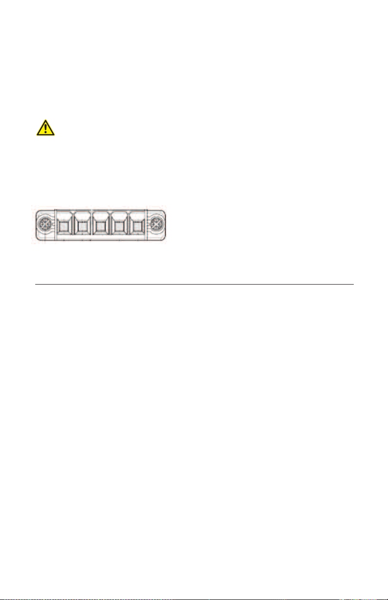
The BlueCure lamp is connected with the power supply via a respective cable.
A 5-pin plug from Phoenix Contact is used for the connection (Type: PC5/5-STF1-7,62).
Connect the power supply cable of the lamp to the power supply according to the
instructions provided by the manufacturer of the power supply.
CAUTION!
Attention: Do not plug in or disconnect the plug while under voltage. For this
purpose, turn the power supply off first.
V+ V- PE V- V+
Pin Function Signal Level Remark
V+ Input voltage +47 to +49 V DC +48 V DC input to the power supply of the lamp; cable color: red
V- Reference mass 0 V DC Grounding for +48 V DC power supply of the lamp; cable color: black
PE Grounding (PE) 0 V DC Cable color: green or green-yellow
V- Reference mass 0 V DC Grounding for +48 V DC power supply of the lamp; cable color: black
V+ IInput voltage +47 to +49 V DC +48 V DC input to the power supply of the lamp; cable color: red
14
Page 15

5.3 Possible Connection Scenarios
Scenario 1:
- Simple on/off (no SPS)
- 100% intensity (not adjustable)
- No monitoring of errors and temperature
- No emergency shut-off functionality
S1 = On / off lamp
T1 = Power supply
Scenario 2:
DB15 Interface
LAMP
Power supply
Phoenix Contact 5-pin
- Simple on/off (no SPS)
- Adjustment of the intensity from 20 to 100%
- No monitoring of errors and temperature
- Temperature monitoring via an external voltmeter
- No emergency shut-off functionality
S1 = On / off lamp
V1 = external voltmeter for checking the internal
temperature of the lamp
P1 = Intensity setting from 20 to 100%
T1 = power supply
DB15 Interface
LAMP
Power supply
Phoenix Contact 5-pin
15
Page 16
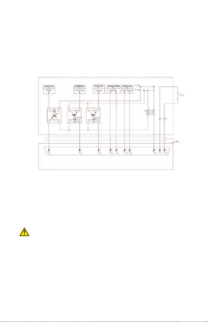
Scenario 3:
- SPS-controlled
- Adjustment of the intensity from 20 to 100% via SPS
- Monitoring of errors via SPS
- Temperature monitoring via SPS
- Emergency shut-off functionality
3 = Emergency shut-off switch
S
2 = DC regulator
T
DB15 Interface
LAMP
6 On/Off Control
The BlueCure lamps can be turned on or off in less than 50 ms via a control
voltage; for this reason, a shutter is not necessary. The lamp will only be activated
if it is needed.
CAUTION!
Attention: If the lamp is not needed, turn it off to prevent heat from building. Even
if the surface of the lamp does not heat up, high temperatures may
develop in the area surrounding the lamp (e.g. every material in the
direct proximity, for which there is no air circulation).
16
Page 17
7 Intensity of the Radiation
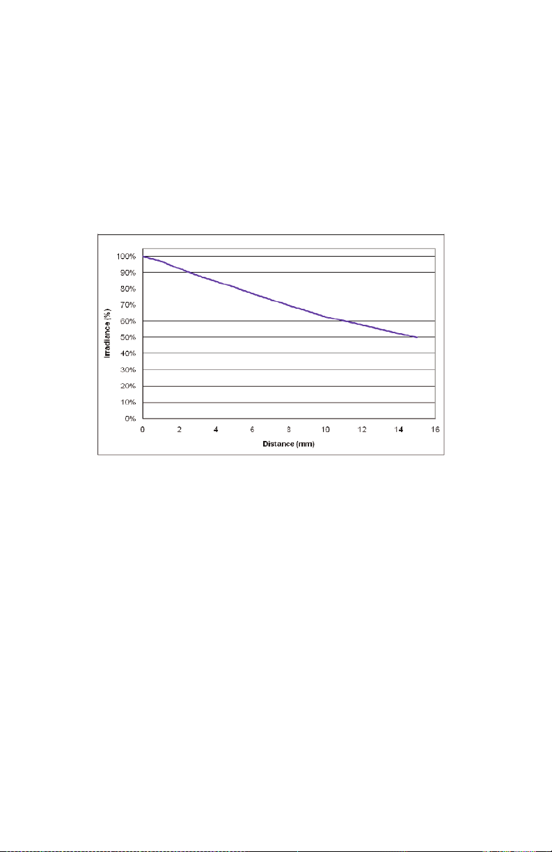
BlueCure lamps are flood lamps. Therefore, the highest intensity is achieved a
close as possible to the radiation window of the lamp. A typical distance between
the light source and the substrate to be exposed is approx. 5 mm.
Lamps with a wavelength-peak of 395 nm emit light within the wavelength range of
380 to 420 nm.
With an increasing distance between the light source and the substrate, the
intensity of the radiation as a function decreases. The specified maximum intensity
is measured directly on the glass surface of the light-emitting window.
The output capacity of the water-cooled lamps is directly influenced by the
temperature of the coolant and the water through-flow quantity. The irradiance will
slightly increase with cooler operational temperatures, e.g. when first turning the
lamp on.
Because the coolant extensively cools the cooling element of the lamp in certain
operating conditions (for expelling heat), condensation may form in the lamp behind
the glass of the light-emitting window after the lamp is turned off and the cooler
continues to run.
We recommend monitoring the temperature continually via pin 15 of the DB15 plug
(Output Temperature Monitor). If the measured temperature deviates from the usual
operational conditions by more than 10 to 15 °C, this could be an indication that
significant changes have occurred in the operating environment of the lamp.
Every lamp is additionally equipped with an internal temperature switch in order to
prevent overheating and, thus, damaging the lamp. If the maximum temperature is
exceeded, the lamp will automatically shut off. After re-cooling, it will automatically
turn back on when it has reached a lower temperature level. It is imperative to
comply with the operational temperature and coolant temperature at the inlet
specified (see 4 Technical Specifications).
17
Page 18

8 Maintenance
The glass surface where the light is emitted should be occasionally inspected for
potential contaminants and, if necessary, cleaned. Use a soft cloth soaked in
alcohol for this. Do not flood the lamp with cleaning liquid in the process.
The maintenance of the cooling system is primarily geared toward the used
refrigeration unit. When using decalcified water with an anti-algae additive, no
maintenance to the cooling circuit should be expected. However, if calcium and
algae deposits do occur, we recommend the following process for cleaning the
lamps:
1. Run a solution consisting of vinegar and decalcified water (Mixing ratio 1:1 n.
weight) through the lamp for 15 minutes
2. In the next step, run a pure vinegar solution through in the opposite direction for
15 minutes.
3. Next, run decalcified water through for 15 minutes.
4. Finally, run decalcified water through in the opposite direction for 15 minutes.
CAUTION!
Attention: Do not use additives or cleaning solutions that contain salts or chlorine.
9 Accessories
The BlueCure lamps can be operated by using an adapter attachment with fiber
optics or liquid light conductors, which enable a localized exposure with highintensity UV light even on areas that are difficult to access.
Please contact us for more detailed information.
18
Page 19

10 Troubleshooting
Symptom Component Potential Cause and Remedy
The lamp does
not emit any
light
Power supply - Check whether all cables are connected to the power
supply properly
- For this, follow the respective instructions of the power
supply manufacturer
- Check whether the power supply is plugged in
- Check whether the voltage from the power supply to the
source of radiation is +48 V DC
Temperature fault If the lamp displayed a temperature fault, no light will be
emitted until the lamp has reached a safe operating
temperature. (see also: Water-cooling below)
SPS control See 5.1 ‘SPS Connection’ for troubleshooting the interface
DB15. It is possible to test-run the lamp without SPS. Turn
on the lamp with full intensity with the following bridges to
the DB15 interface:
- Turn on the lamp with a low signal: Bridge between pin 4
and pin 10
- Emergency shut-off functionality: Bridge between pin 7 and
grounding pin 14
- Lamp output: Bridge between pin 2 and pin 6
SLM error - Check the wiring of the DB15 connection; see 5.1 ‘SPS
Connection’ for this.
- If the outlet pin 11 from the DB15 is applied to the ground
(0 to +0.4 V DC), then it is possible that an internal fuse
was set off. For further information, contact Nordson EFD.
Temperature
increase of the
lamp by more
than 15°C
Film on the
inside of the
glass window
of the lamp
Water-cooling - Check for the proper coolant through-flow
- Check the coolant temperature at the coolant inlet of the
lamp (maximum +20 °C)
- If the lamp briefly (< 5 minutes) displayed a temperature
fault, check whether the temperature of the lamp is less
than +40 °C. To determine the internal temperature of the
lamp, you will need a voltmeter. Measure on pin 15
against the ground (+2 V = +20 °C).
Water-cooling Check the environmental conditions of the light source for
potential signs of condensation. The film could be formed by
the collection of condensation on the inside of the lamp.
19
Page 20
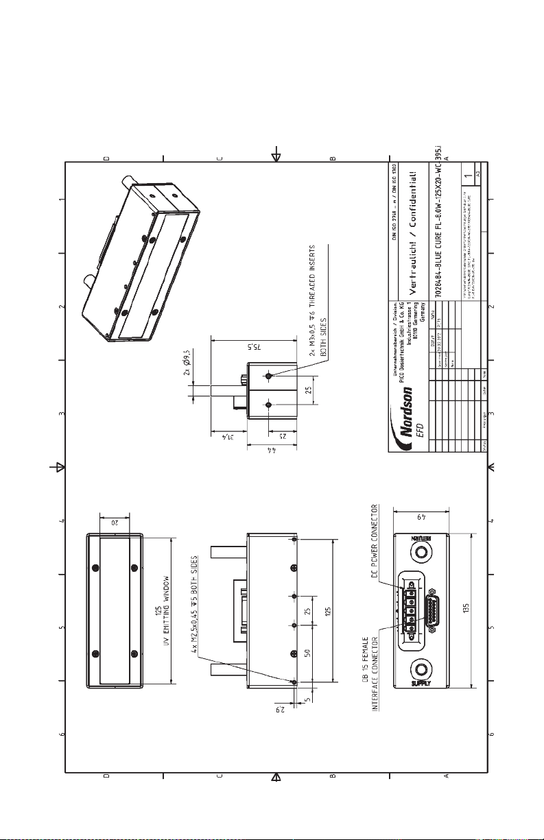
A. Appendix
A.1 Drawing of the BLUE CURE FL-8.0W-125X20-WC-395
20
Page 21

21
Page 22

For Nordson EFD LLC sales and
service in over 30 countries,
contact Nordson EFD or go to
www.nordsonefd.com
East Providence, RI USA
USA & Canada: 800-556-3484
+1-401-431-7000
[email protected]
Dunstable, Bedfordshire, UK
0800 585733; +44 (0) 1582 666334
Ireland 00800 8272 9444
[email protected]
Germering, Germany
+49 (89) 8493 6660
[email protected]
China: +86 (21) 3866 9006
[email protected]
Singapore: +65 6796 9522
[email protected]
The Wave Design is a trademark of Nordson Corporation.
©2012 Nordson Corporation
7015892 v031612
This equipment is regulated by the European Union
under WEEE Directive (2002/96/EC). See
www.nordsonefd.com for information about how to
properly dispose of this equipment.
NORDSON EFD ONE YEAR LIMITED WARRANTY
Nordson EFD products are warranted for one year from date of purchase to be free from defects in material
and workmanship (but not against damage caused by misuse, abrasion, corrosion, negligence, accident, faulty
installation or by dispensing material incompatible with equipment) when the equipment is installed and
operated in accordance with factory recommendations and instructions. Nordson EFD will repair or replace free
of charge any part of the equipment thus found to be defective, on authorized return of the part prepaid to our
factory during the warranty period. In no event shall any liability or obligation of Nordson EFD arising from this
warranty exceed the purchase price of the equipment. This warranty is valid only when oil-free, clean, dry,
filtered air is used.
Nordson EFD makes no warranty of merchantability or fitness for a particular purpose. In no event shall Nordson
EFD be liable for incidental or consequential damages.
22
 Loading...