

Page 1
Installation, Operation and Maintenance Manual
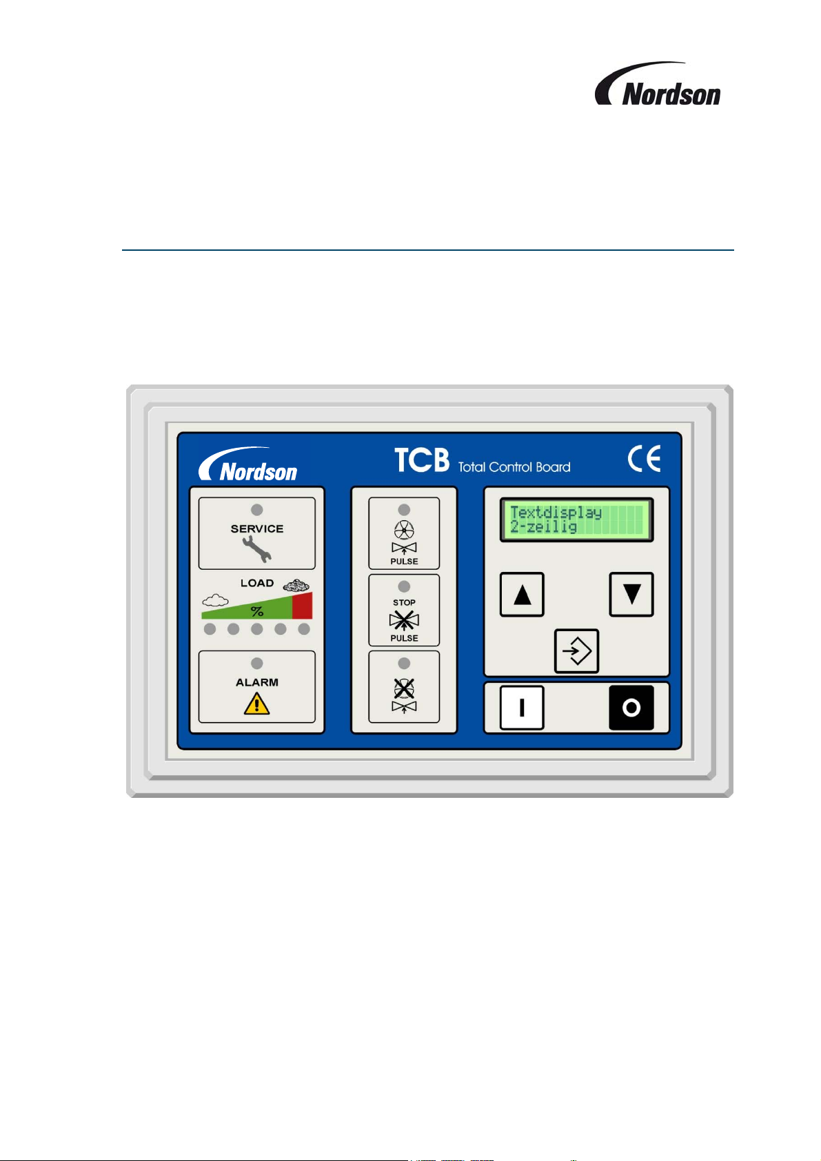
Total Control Board
7146919-05 (GB) 0610
Freedom from patent restrictions must not be assumed.
Page 2

Installation, Operation and Maintenance Manual
7146919-05 (GB) 0610
Freedom from patent restrictions must not be assumed.
Page 3
Installation, Operation and Maintenance Manual
IMPORTANT
PLEASE READ THIS MANUAL CAREFULLY BEFORE INSTALLATION
THIS MANUAL SHOULD BE READ IN CONJUNCTION WITH THE RESPECTIVE
PRODUCT MANUAL AND CIRCUIT DRAWINGS SUPPLIED WITH THE
AFTERFILTER
EXPLANATIONOFSYMBOLSUSED
Refers to special information regarding the most efficient use.
Refers to special information directed towards preventing damage.
Refers to special information designed to prevent injury or extensive damage.
3
Page 4

Installation, Operation and Maintenance Manual
TABLEOFCONTENTS
1. Introduction 6
2. Delivery and MOUNTING INSTRUCTIONS 8
2.1. Enclosure location 8
2.2. Pneumatic installation 8
3. Electrical installation 9
3.1. Main switch IP65 9
3.2. Motor connection 9
3.3. Supply voltage: terminals 1 and 2 10
3.4. RS-485 Bus: terminal 3–5 10
3.5. Motor protection: terminals 25, 28 10
3.6. Optional isolation amplifier for thermistor protection and/or bursting disc: terminals 6–9 11
3.7. Connections for Fan starters : terminals 14–17 (+ 12 & 13 for ECB 4 units) 11
3.8. Alarm relay: terminals 18–20 11
3.9. Remote start/stop push buttons: terminals 21–23 11
3.10. Input external on: terminal 24, 28 11
3.11. Outputs for remote control lamps: terminals 29–31 12
3.12. Optional analogue output: terminals 32–34 12
3.13. Valve outputs: terminals V1–V16 – Single module systems 12
3.14. Valve outputs: terminals V1–V16 – Multiple module systems 12
3.15. Rotary switches “Slave address” and “mode”. 12
3.16. Programmable inputs 13
3.17. Programmable outputs 13
4. Pre-Start-up checklist 15
5. Operation 15
5.1. Single Fan Afterfilter Systems 15
5.2. Multiple Fan Units e.g. ECB Units 15
5.3. Status LED’s 16
6. Using the menu system 17
6.1. Display mode 17
6.2. Setting mode 17
7. Parameter/Memory fields description 19
7.1. P00 Setting Pin code 19
7.2. P02 Delta P Min 19
7.3. P03 Delta P Max 19
7.4. P04 Delta P Max Alarm 19
7.5. P05 Low Pressure Alarm 19
7.6. P06 Off Line cleaning Cycles 20
7.7. P07 Star/Triangle switch over Time 20
7.8. P09 Cleaning Pulse interval 1 20
7.9. P12 Cleaning valve Pulse time 20
7.10. P15 display Language 20
4
Page 5

Installation, Operation and Maintenance Manual
7.11. P17 Function of Input I1 (terminals 26-28) 21
7.12. P18 Function of Input I2 (terminals 27-28) 21
7.13. P19 Function of output relay O1 (Relay contact cleaning on / terminals 10-11) 22
7.14. P20 Function of Optional output relay O2 (Relay contact start extracting equipment / terminals 12-13)22
7.15. P22 Delta P Cleaning mode 23
7.16. P26 Number of valves 23
7.17. P40 Time/Date Display 23
7.18. P41 Set Time and Date 24
7.19. P44 Program Version 24
7.20. P46 Active Pulse Display 24
7.21. P48 Test Display 24
7.22. P50 Back To Factory Settings 25
7.23. M05 Total Operating Hours 25
8. ALARM MESSAGES and fault location 26
9. Maintenance 29
10. Options and features 29
11. Specifications 30
12. Spare Parts 30
13. EC DECLARATION OF CONFORMITY 31
TABLEOFFIGURES
F
IGURE 1:
IGURE 2: TERMINAL VIEW OF
F
F
IGURE 3: WIRING DIAGRAM MODULE
IGURE 4: DISPLAY
F
TCB
FRONT PANEL
PCB
....................................................................................................................................... 7
I/O
BATTERY
MODULE
.............................................................................................................................. 29
PCB ........................................................................................................... 10
PCB (
DETAIL
) ..................................................................................................... 11
5
Page 6
Installation, Operation and Maintenance Manual
1. INTRODUCTION
It is a requirement of the Supply of Machinery (Safety) Regulations 1992 to provide adequate
isolation and emergency stop facilities. Due to the varied nature of site installations this cannot
be provided by Nordson but instead is the responsibility of the customer.
For installation in hazardous areas, all work must be carried out with the electrical supply
isolated or only when the potentially explosive atmosphere is not present. Checks should be
made to ensure the category of equipment is suitable for the zone in which the installation is
made.
All electrical work has to be done by a qualified electrician according to the national and local
electric codes that apply. (EN60204.1, IEC 364).
All electrical power must be shut off during installation of the Control Board.
Do not apply power on any circuits before all connections have been made.
On outside installations, always isolate power before opening the controller in wet weather
conditions.
The Control Board provides following functions:
Starting and stopping of the cleaning function at the assigned (adjustable) set points, initiating the
individual pulses in an appropriate sequence, providing the correct time interval between pulses,
energizing the solenoid valve for the proper length of time, and also providing the logic to control
the alternate cleaning modes
Connection of up to 32 valves in parallel mode. (16 valves for the light version - based on 22w /
Valve).
Connection of up to 96 valves in a serial linked, multi module system. (based on 22w / Valve).
Operation of multiple fan systems (e.g. ECB units) under either standard or ‘ATEX‘ mode
cleaning.
An LCD-display showing all settings and alarm messages
Push buttons to start and stop the fan
Overload protection of the fan(s).
A visual display of the pulse cleaning
A bar graph indicating the differential pressure over the filter elements
Possibility to set an adjustable off-line cleaning cycle
A visual display of the off-line cleaning cycle when set
‘Stop-and-go’ or ‘stop-and-end’ setting (explanation: see chapter 7.11)
Programmable input and output functions
Optional remote control installation
Optional alarm installation
6
Page 7
Installation, Operation and Maintenance Manual
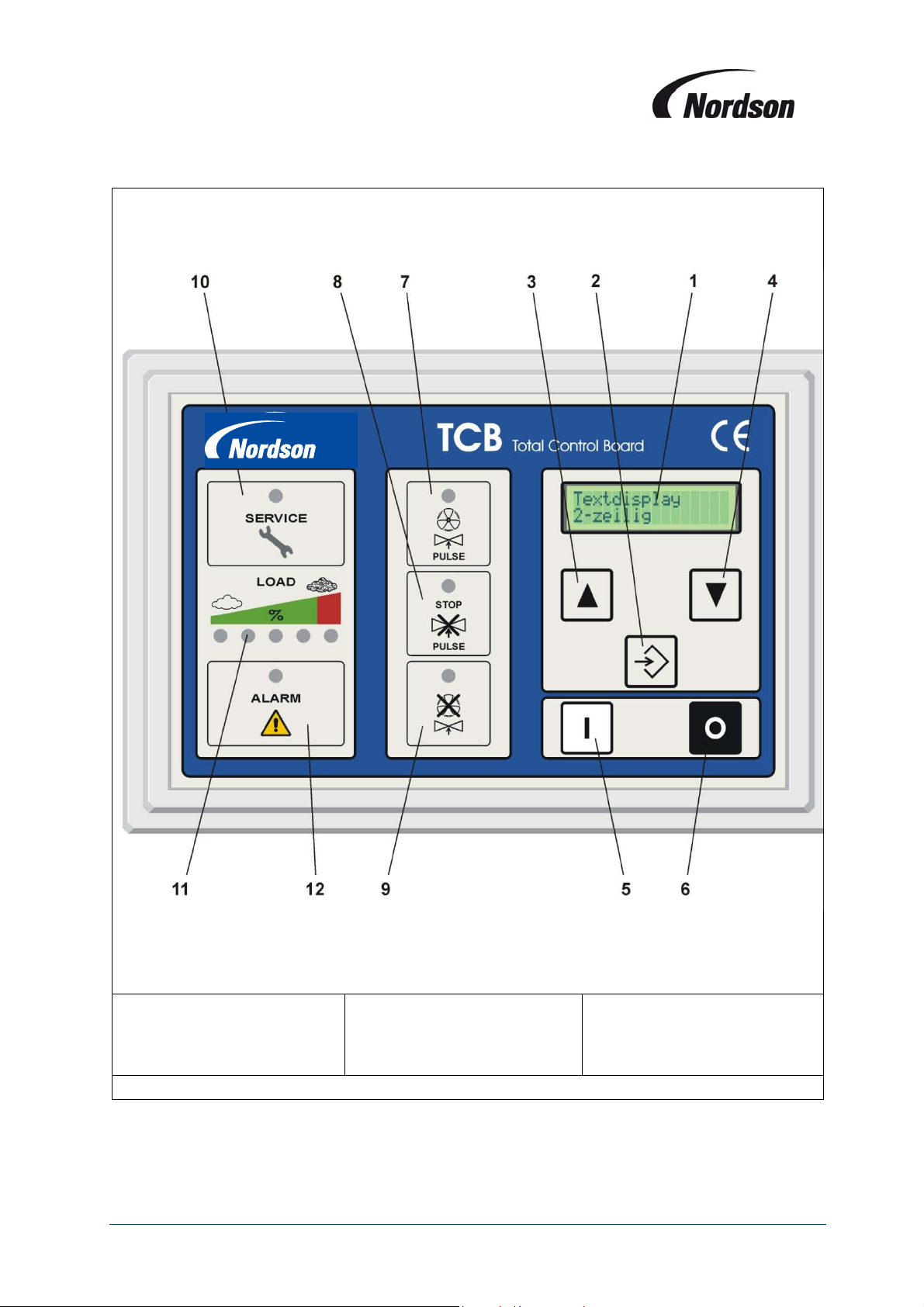
1. LCD-display
2. ENTER-button
3. Scroll UP button
4. Scroll DOWN button
5. Push Button fan ON
6. Push button fan OFF
7. LED ‘FAN ON / PULSE’
8. LED ‘Cleaning stopped’
Figure 1: TCB front panel
7
9. LED ‘Off-line Cleaning’
10. LED ‘Service’
11. LED bar-graph indication
of differential pressure
12. ‘Alarm’ LED
Page 8
Installation, Operation and Maintenance Manual
2. DELIVERYANDMOUNTINGINSTRUCTIONS
The TCB is normally delivered pre-mounted and pre-wired with the Afterfilter. In case the TCB is
shipped loose with the unit, follow the next steps to ensure a faultless functioning of the control box.
When the Control Board is received, verify that the enclosure has not been damaged during
shipment. Compare the items received against the packing list. If you find any components that
are damaged or missing, notify the delivery company and your local Nordson representative.
Unpack the Control Board enclosure. Some items may have been shipped inside the enclosure.
Remove any packing material and dispose of it properly.
Items shipped loose with the Control Board may include:
Slave Solenoid valve enclosures
safety filter
wiring diagram
installation and operation manual
spare fuses
2.1. Enclosure location
The enclosure of the Control Board should be mounted in a location convenient for the operator or
maintenance personnel. Since the display provides visual warning of problems and operating
conditions, much of its value is lost if the location does not permit continuous observation. For the
longest, most trouble-free operation, mount the enclosure on the unit or a wall/column with little or no
vibration.
The distance away from the Afterfilter is limited by the length of tubing and cable supplied with the
equipment (standard 10 m).
In order to get reliable signals to the sensors, the Control Board’s pneumatic sensor lines should not
exceed 20 m. Lengths in excess of this may weaken the signals to the point that they are not reliable.
Contact your Nordson representative for assistance if the sensor lines must be longer than 20 m.
If the area in which the controller is to be located is defined as a hazardous area check to ensure the
rating of the controller supplied is suitable for this area.
2.2. Pneumatic installation
The Afterfilter has tubing fittings installed in the clean air plenum and the dirty air plenum. Attach one
tube from the clean air plenum to the low pressure fitting on the enclosure (blue connector). Attach the
other tube from the dirty air plenum to the high-pressure fitting (black connector). All connections need
to be airtight.
To avoid ingress of powder into the controller pressure transducer, it is recommended that an
in-line filter is fitted between the dirty side of the collector and the controller connection. For
collectors handling explosive powders this filter must be used in both the clean and dirty side
connections.
8
Page 9
Installation, Operation and Maintenance Manual
3. ELECTRICALINSTALLATION
For the connections to the control box see the wiring diagram shipped inside th e enclosure.
All electrical work must be done by a qualified electrician according to the national and
local codes that apply.
3.1. Main switch IP65
The incoming power is connected to the terminals on the main switch inside the enclosure. On standard
power boxes the main switch will be mounted on the door. The enclosure cannot be opened without
first turning off the power to the box (main switch in position ‘0’).
A neutral terminal is provided for termination of a neutral conductor. The neutral connection is not
however required for operation of the controller.
Do not attempt to wire any electrical components while energized. Electrocution
and/or damage to the components may occur.
Connect power supply to the main switch.
When the control board is not factory pre-wired to the Afterfilter make the other connections
to the terminals as per table on page 13.
3.2. Motor connection
For pre-wired units the motor connections will be made directly to the contactors of the fan according
the wiring diagram delivered inside the TCB enclosure.
For controllers shipped loose connections should be made to the DIN rail terminals according to the
wiring diagrams delivered inside the TCB.
9
Page 10
Installation, Operation and Maintenance Manual
4
3
2
1
5 6 7 8 9 10 11 19
Fuse T 2A
+24V DC
12 14 16 17 18
13 15
+24V DC
+24V DC
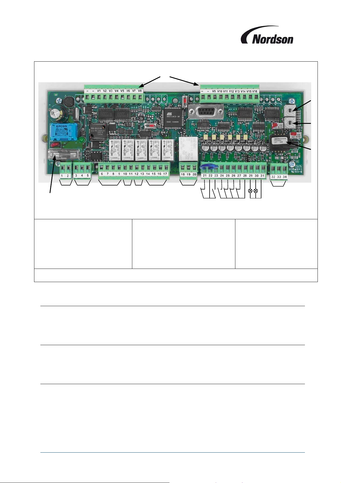
1. Pressure transducer
2. Cleaning mode switch
3. Module number switch
4. Valve connectors
5. Input voltage 24 VAC
6. RS 485 bus link
(Terminal Numbers)
(-, V1 – V16)
(3,4,5)
(1,2)
7. Optional isolation amplifier
8. Output O1
9. Optional output O2
10. Fan starter
11. Alarm relay
12. Remote ON/OFF terminals
13. External ON
(10,11)
(14 – 17)
(18 – 20)
(28, 24)
Figure 2: Terminal view of I/O module PCB
3.3. Supply voltage: terminals 1 and 2
The supply voltage for the power box can be either 200V AC, 230V, 380V, 400V (standard TCB), 440V
or 480V, 50 or 60 Hz. A transformer with 63VA or 110VA output will be used. The electronic modules
will be supplied with pre-wired 24V AC on terminals 1 and 2.
3.4. RS-485 Bus: terminal 3–5
All TCB Circuit boards have an RS-485 interface for the communication between Display, I/O module
and slave valve modules. For multiple module systems the RS485 connection is pre-wired to socket
connections on the base of the main controller and the ends of the slave modules.
(12,13)
(6 - 9)
(21- 23)
14. Fan alarm
15. Alarm input I1
16. Alarm input I2
17. ‘In use’ lamp
18. ‘Alarm’ lamp
19. 4 – 20 mA
terminals
(28, 25)
(28, 26)
(28, 27)
(31, 29)
(31, 30)
(32 – 34)
3.5. Motor protection: terminals 25, 28
An overload relay is used for the fan motor(s); the auxiliary contact will be connected to terminals 25
and 28 (multiple fan overloads will be connected in series). When the fan alarm triggers a shutdown of
the fan set, a re-start is only possible after shutting down the power to the control box and re-setting the
overload switch.
10
Page 11
Installation, Operation and Maintenance Manual
3.6. Optional isolation amplifier for thermistor protection and/or bursting disc: terminals 6–9
An optional isolation amplifier for motor thermistor protection or bursting disk observer circuit can be
plugged into the I/O module PCB. The input connections will be made to terminal 6 and 7; at terminal 8
and 9 a potential free contact (NC) is available as output signal. This output signal can then be used for
example to initiate an alarm in the TCB by connecting it to terminals 26 and 28.
The terminals for the thermistor will be included as standard on the TCB board, but the Thermistor
module itself is an option.
3.7. Connections for Fan starters : terminals 14–17 (+ 12 & 13 for ECB 4 units)
The contactors for fan starting will be connected as follows:
Terminal 14 = Common = 24V AC Supply.
Terminal 15 = Main contactor for Star-Delta systems, Fan 1 contactor for DOL / multiple fan systems.
Terminal 16 = Star contactor for Star-Delta systems, Fan 2 contactor for multiple fan system
Terminal 17 = Delta contactor for Star-Delta systems, Fan 3 contactor for multiple fan system.
For a 4 fan system :
Terminal 12 = Common = 24V AC Supply.
Terminal 13 = Fan 4 contactor.
These connections are made at the factory.
3.8. Alarm relay: terminals 18–20
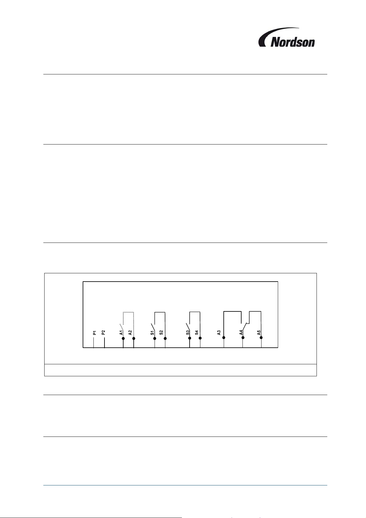
A change over contact is available on terminals 18-20. The relay is normally energised and is deenergised when an alarm condition occurs (red alarm lamp on the display lights up) or when a power
failure occurs (see Figure 3 schematic below).
6 7 8 9 10 11 12 13 18 19 20
Figure 3: Wiring diagram module PCB (detail)
3.9. Remote start/stop push buttons: terminals 21–23
The external ON/OFF push button circuit can be connected to terminals 21-23. The terminals 21 and 22
are connected ex works. To start the fan set: momentarily close contact 23 and 22 (Normally open
contact). To stop the fan set: momentarily open contact 21 and 22 (normally closed contact).
3.10. Input external on: terminal 24, 28
The input terminal 24 can be used to start the filter from an external potential free contact. Closing the
contact = fan start, cleaning operational; opening the contact = fan off. In this case terminals 21 and 22
(remote stop) are bridged.
11
Page 12
Installation, Operation and Maintenance Manual
Note all stop / start signals have equal priority and the system can be stopped and started
using the display or remote stop buttons even if terminals 24 and 28 are bridged. To restart
from terminals 24 and 28 this connection must be opened and re-closed. The fan will not start
when the main power is turned on even if 24 & 28 are bridged.
3.11. Outputs for remote control lamps: terminals 29–31
Outputs for ‘Alarm’ and ‘Fan on’-lamps; 24 V maximum load 2W.
3.12. Optional analogue output: terminals 32–34
When this option is supplied a sensor with accuracy of 2,5% will be used. The analogue output is
available at terminals 32-34. The usage of the 0.5% accuracy sensor is possible (at an additional cost).
Optionally the terminals 32-34 can be used as analogue 4-20 mA input (ATEX zone 1 or 2 applications
using external pressure transducer). Terminal 32 = Ground; 33 = in - or output signal sensor; 34 =
Common (+).
3.13. Valve outputs: terminals V1–V16 – Single module systems
The (-) connection of the valves will be made to terminals V1 to V16. The outputs have a maximum load
of 1.9A (45W at 24V DC). The outputs are short circuit and over voltage protected. Up to two solenoid
valves (22W) per output terminal can be connected, so 32 valves in total.
3.14. Valve outputs: terminals V1–V16 – Multiple module systems
Where the TCB is used to operate more than 32 valves a serial linked system is used. The master TCB
will contain an I/O module for connection of motor contactors, alarms, input and output signals. Valves
will be connected using 3 or more slave modules connected to the system using the RS-485 bus
connection. Each slave module contains an PCB pre-wired to the solenoids – max 16 / module.
The slave modules should be connected together and to the master TCB using the connecting leads
supplied.
3.15. Rotary switches “Slave address” and “mode”.
The two rotary switches “slave address” and “mode” are used to set the module number and cleaning
mode. The setting of switches is for the master and pre-mounted slave modules are done in the factory
and should not be changed. For modules assembled to the collector on site set the slave address
switches as detailed below.
Settings are as follows:
Master system – Slave Address = 0,
Mode = 0
Slave modules – Slave address = 1, 2, 3, …. Etc – 1 = Nearest to the master controller.
Mode = 0
12
Page 13

Installation, Operation and Maintenance Manual
3.16. Programmable inputs
Two additional alarms / inputs can be connected to the terminals 26, 27 and 28. The function of these
alarm inputs can be selected by the software (see chapter 7.11).
Input I1 = terminals 26-28, Input I2 = terminals 27-28. Terminals bridged = no alarm / input, opening
connection = alarm / input active.
3.17. Programmable outputs
Two programmable outputs (volt free contacts) are available on terminals 10,11 & 12,13
The function of these outputs can be selected by the software (see chapter 7.13).
Default settings are :
Output 1 – contact closed when cleaning is active. (Setting = 01 - Cleaning on)
Output 2 – contact closed during fan operation and off-line cleaning. (Setting = 03 - Fan on +)
Note : The programmable outputs 1 and 2 are not available in multi fan ECB systems as the
relays are used to connect fan contactors in these configurations.
13
Page 14
Installation, Operation and Maintenance Manual
V
r
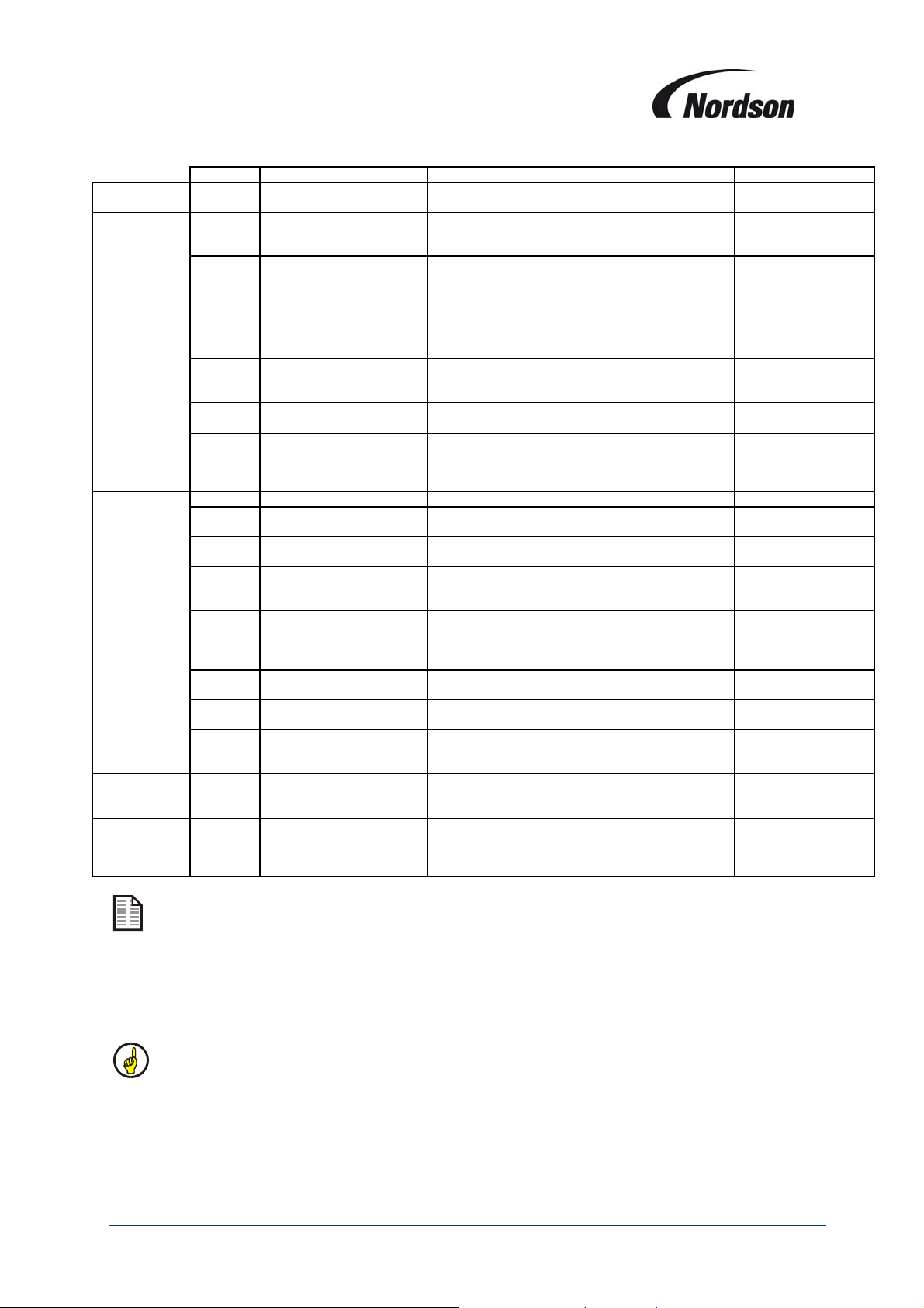
Terminal Item Description Remarks
Bus
Connection
Outputs 8, 9 Thermistor / bursting disc
10, 11 Programmable output O1
12, 13
29, 31 ‘Fan on’ lamp Output for external control lamp “fan set operational” 24VDC, Max load 2W
30, 31 Alarm lamp Output for external control lamp “Alarm” 24VDC, Max load 2W
Optional
Inputs
22, 23 Input remote switch ‘ON’
21, 22 Input remote switch ‘OFF’
24, 28 Input external ‘ON’
25, 28 Fan alarm input terminal
26, 28
27, 28
Optional
Valves
+ Valve connection + (plus) Output for the common (+) connection of the valves.
Fan
3,4,5 RS 485 Bus connection
Optional programmable
output O2
18, 19,
20
32, 33,
34
1, 2 Supply voltage 24 V AC Supply voltage for PCB
6, 7 Thermistor / bursting disc
32, 33,
34
V1 to
16
14, 15,
16, 17
General alarm
4-20 mA output signal
Programmable alarm input
I1
Programmable alarm input
I2
4-20 mA input signal
Valve connection - (minus) Output for the (-) connection of the valves See notes below.
Contactor fan motor(s)
Serial link connection between display and I/O
modules
Relay output signal for Thermistor circuit or bursting
disc Reed-contact.
The contact closes during cleaning as default
setting.
(Used for fan 4 in multi-fan ECB configurations)
The contact closes during fan operation and off-line
cleaning as default setting.
(Used for lighting circuit in multi-fan ECB
configurations)
19 Common, 18 Normally Open, 20 Normally
Closed.
Analogue output for differential pressure (4 mA = 0
daPa, 20 mA = 500 daPa).
Optional input for Thermistor circuit or Bursting disc
reed contact.
Input to connect a remote switch (in parallel): ON
(terminal 22 holds + 24 VDC)
Input to connect a remote switch (in parallel): OFF
(terminal 22 holds + 24 VDC)
Input to connect an external contact for fan
operation (terminal 28 holds +24 VDC)
Overload relay for fan motor (terminal 28 holds + 24
VDC).
When contact opens an alarm message is displayed
as default setting.
When contact opens an alarm message is displayed
as default setting.
Analogue 4-20 mA input signal. 32 Ground, 33 in- or
output, 34 common. (ATEX zone 1and 2
applications)
Terminal 14: Common connection
Terminal 15: Mains contactor (ECB Fan 1)
Terminal 16: Star contactor (ECB Fan 2)
Terminal 17: Delta contacto
(ECB Fan 3)
Max. contact load of
relays: 5 A - 230 VAC
/ 2 A - 24 VDC
Max. contact load of
relays: 5 A - 230 VAC
/ 2 A - 24 VDC
Max. contact load of
relays: 5 A - 230 VAC
/ 2 A - 24 VDC
Max. contact load of
relays: 5 A - 230 VAC
/ 2 A - 24 VDC
4 – 20 mA
Recommended
external resistance
150-250 Ω
Use a potential free
NC contact
Use a potential free
NO contact
Use a potential free
NC contact (Supplied
bridged ex-works)
Use a potential-free
NO contact
Use a potential free
NC contact
Use a potential free
NC contact
Use a potential free
NC contact
4 –20 mA
Max. contact load of
relays: 5 A - 230 VAC
/ 2 A - 24 VDC
Terminals 8 to 20 are connected with potential-free contacts rela ys.
All valve connections made with the I/O module PCBs must be in numerical sequence witho ut
gaps.
I/O module PCBs have only RS485 bus and valve connection terminals.
Relays used for solenoid control have a maximum loadings as follows:
1.9A (45W at 24V DC) for master I/O module – suitable for connection of 2 valves of 22W in
parallel.
1.0A (25W at 24V DC) for slave I/O modules – 1 pre-connected valves of 22W only.
Only one valve per compressed air manifold can be operated at the same time.
14
Page 15

Installation, Operation and Maintenance Manual
4. PRE‐START‐UPCHECKLIST
Make sure all connections to both air and electrical supplies are in the correct position
(when not pre-mounted).
Recheck all the electrical and air connections for tightness.
Verify that all electrical systems have been properly grounded.
Verify if the motor protection switch setting matches the motor full load current.
Check the star/delta change over delay setting. Factory default is at 5 seconds, but it can
be adjusted in the setting mode (see chapter 7.7).
For a multi-module system ensure all interconnecting cables are in place and mode and
address switches are set correctly.
After the electrical connections are in place ensure that the door is correctly closed and
secured. The enclosure is designed so the main switch needs to be turned off before the front
panel can be opened.
5. OPERATION
5.1. Single Fan Afterfilter Systems
The TCB control board provides the output signals to the diaphragm valves mounted on the Afterfilter
and also controls the fan motor start-up procedure (and can controls other auxiliary equipment if fitted –
e.g. rotary valve, screw conveyor etc). The differential pressure measured gives a clear indication of the
pressure loss over the filter elements.
By default the unit will start pulsing when the threshold value of 80 daPa is exceeded. A cleaning cycle
normally pulses all valves of the unit in sequence with an interval of 10 seconds between every pulse.
As soon as the differential pressure drops below 40 daPa, the controller will stop the cleaning when a
full cycle is completed; this is called ‘Stop & End’ cleaning.
The LCD display will indicate the status of the unit during operation e.g. SYSTEM ON, CLEANING ON
etc. as well as indicating the current filter differential pressure.
When the differential pressure rises above 150 daPa, an alarm message will be displayed and the
alarm LED will illuminate.
The off-line clean function allows the cleaning cycle to continue for a number of cycles after the fan has
been switched off. This function is switched off by default but can be initiated by altering parameter
P06.
These factory default values can be altered when needed using the guidelines detailed in the following
chapters.
5.2. Multiple Fan Units e.g. ECB Units
The TCB control board provides the output signals to the diaphragm valves mounted inside the
Afterfilter and also controls the fan motor start-up sequence. The differential pressure measured gives a
clear indication of the pressure loss over the filter elements.
For standard units handling non-explosive powders the cleaning will, by default, start pulsing when the
threshold value of 80 daPa is exceeded. A cleaning cycle normally pulses all valves of the unit in
sequence with an interval of 10 seconds between every pulse. As soon as the differential pressure
15
Page 16

Installation, Operation and Maintenance Manual
drops below 40 daPa, the controller will stop the cleaning when a full cycle is completed; this is called
‘Stop & End’ cleaning.
If off-line cleaning is to be carried out this is done one module at a time, the fans of the other modules
maintaining suction in their respective unit sections to avoid powder clouds being generated outside the
unit.
The number of cleaning cycles carried out depends on the pressure drop at the time the unit is stopped,
the number of cycles set and also the pressure drop across the filters during the cleaning cycle. This
sequence is designed to optimise the cleaning effectiveness while minimising air usage and cleaning
time. During off-line cleaning the display will indicate the module being cleaned and the number of
cycles remaining.
For ECB units handling explosive powders, and hence operating in a hazardous area the cleaning
sequence is carried out only when the unit is off-line using the sequence described above. Cleaning on
line is not initiated, regardless of filter differential pressure, to avoid generating a potentially hazardous
atmosphere within the collector during periods where the working area outside the unit could potentially
generate ignition sources.
The contactor provided to activate working area lighting is de-energised during off-line cleaning periods.
The software parameters controlling these cleaning sequences are factory set to correspond to the unit
type supplied and installation conditions and cannot be changed.
5.3. Status LED’s
The status LEDs on the front display panel of the TCB have the following meanings:
SERVICE LED - When during normal operation the service LED lights up, the unit needs to be
checked by a Nordson representative.
LED BAR GRAPH - The LED Bar graph will indicate the actual status of the filter
ALARM LED - The Alarm LED will light up when one of the followings alarms occur:
- Fan overload protection tripped
- One or both additional alarm inputs at the module are “low”
- DeltaP Alarm
FAN / PULSE LED - The Pulse LED will flash when a pulse is active. When the Fan set is
running, this LED will be on. When in the mean time the valves are pulsing, this LED will go out
briefly on every active pulse. When the fan is not running, the LED will be out and flash when a
pulse is active.
PULSE STOP LED - The pulse stop LED will light up when cleaning is not active.
OFF LINE CLEANING LED - The Off-line Cleaning LED will light up during off-line cleaning.
16
Page 17
Installation, Operation and Maintenance Manual
6. USINGTHEMENUSYSTEM
The 3 keys of the control keypad (, , and ENTER) are used to navigate through the menu system of
the Total Control board filter control system. All inputs and messages can be shown on a backlit LCD
display. The menu system is deactivated during normal operation of the system. The actual values
achieved by the system and its operating messages are displayed. This is called the “Display mode”.
Changing of the current settings is done in the “setting mode”.
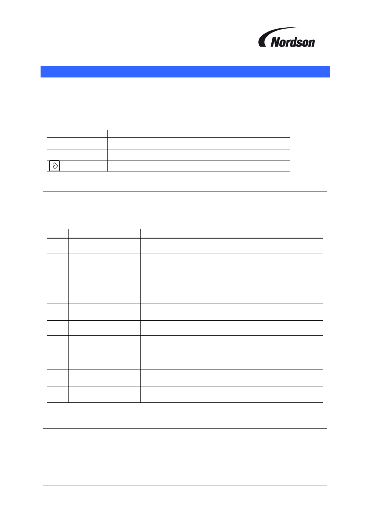
Button Function
GO DOWN in the menu system
GO UP in the menu system
ENTER the menu system or execute a function.
6.1. Display mode
During normal operation the LCD display on the TCB indicates the current differential pressure over the
filter elements. In the display mode it is possible to view all settings without the possibility to change
them. Press ENTER once and scroll up and down the menu using the and buttons. Following
fields can be displayed:
Level Display Description
1.1 EXIT MENU SYSTEM Press ENTER to leave the menu system
1.2
1.3
1.4
1.5
1.6
1.7
1.8
1.9
1.10
DP MIN
P02 xxx daPa
DP MAX
P03 xxx daPa
DP MAX ALARM
P04 xxx daPa
LOW PRESS ALARM
P05 xxx daPa
OFF LINE CLEAN C
P06 xx CYCLES
PULSE INTERVAL 1
P09 xxx SEC
TEST CONTROLLER
P48 END
TOTAL OPERAT H
M05 xxxxxx HOURS
SETTING MODE PIN
P00 xxxx
Show DeltaP Min value
Show DeltaP Max value
Show DeltaP Max Alarm value
Show the Low pressure alarm value
Show number of Offline Cleaning Cycles
Show Pulse Interval
After pressing ENTER all LED’s on the control panel light up for
10 sec.
Show total number of operating hours
Enter PIN code to go to the Setting Mode
6.2. Setting mode
Press ENTER to activate the menu system. You are now in “Display Mode”. By pressing the button
you will see the field “P00: Setting mode PIN”. The system will ask you for the pin code of the Setting
mode when pressing the enter button. Put in the 4 digits one by one with the buttons and to
increase or decrease the value and ENTER to go to the next digit and confirm. The default pin code is
9999. As soon as you enter the setting mode the yellow Service LED will start to blink.
17
Page 18
Installation, Operation and Maintenance Manual
You can now scroll through all parameters in the setting mode. To change a parameter push the
ENTER button and the value can be changed. The new value needs to be confirmed by pushing the
ENTER button again for 2 seconds otherwise the changed value will not be saved, but instead the
message “Program cancelled” will be displayed. The values can only be changed within the range
shown in the last column. The value between brackets is the factory setting. Following fields can be
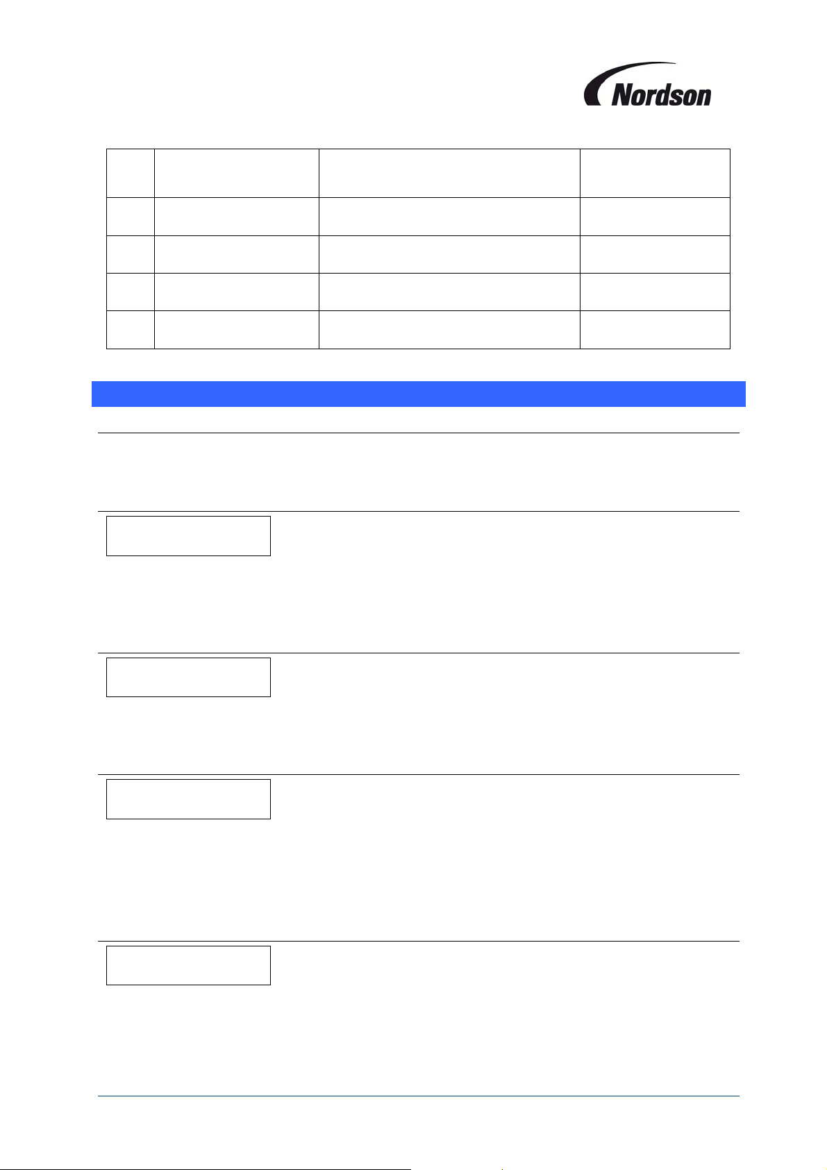
displayed:
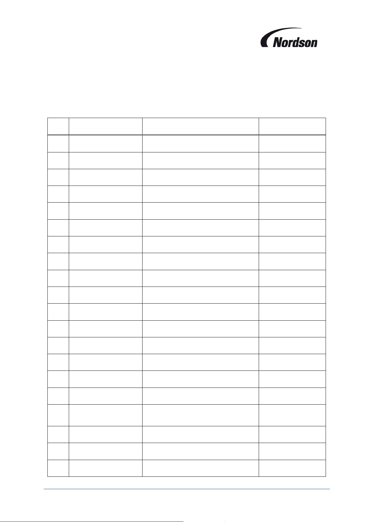
Level Display Description Setting range
2.1 EXIT MENU SYSTEM Press ENTER to leave the menu system
2.2
2.3
2.4
2.5
2.6
2.7
2.8
2.9
2.10
2.11
2.12
2.13
2.14
2.15
2.16
2.17
2.18
2.19
2.19
DP MIN
P02 xxx daPa
DP MAX
P03 xxx daPa
DP MAX ALARM
P04 xxx daPa
LOW PRESS ALARM
P05 xxx daPa
OFF LINE CLEAN C
P06 xx CYCLES
ST TR SW TIME
P07 xxx SEC
PULSE INTERVAL 1
P09 xxx SEC
CLEAN PULSE TIME
P12 xxx MS
DISPLAY LANG
P15 ENGLISH
INPUT FUNCT I1
P17 0 (actual Mode)
INPUT FUNCT I2
P18 0 (actual Mode)
OUTPUT FUNCT O1
P19 0 (actual Mode)
OUTPUT FUNCT O2
P20 0 (actual Mode)
DP CLEAN MODE
P22_(actual Mode)
NUMBER VALVES
P26 xxx VALVES
T/D DISPLAY
P40 (Actual Mode)
DATE
P41 DD.MM.20YY
TIME
P41 hh:mm
PROGRAM VERSION
P44 VXX.XX.XX/X
Setting of DeltaP Min value 10 – 190 daPa (40)
Setting of DeltaP Max value 30 – 340 daPa (80)
Setting of DeltaP Max Alarm value 20 – 350 daPa (150)
Setting of Low pressure alarm value
Setting of Offline Cleaning Cycles 0 – 15 cycles (0)
Setting of Star/Triangle switch time 1 – 60 s (5)
Setting of Pulse Interval 2 – 30 s (10)
Setting of valve Pulse time 40 – 235 ms (100)
Setting the Display Language
Setting the alarm function of input I1.
Setting the alarm function of input I2.
Setting of function for output O1
Setting of function for output O2
Setting of the Delta P Cleaning Mode
Shows the number of valves No setting possible
Setting of summer and winter time or
automatic switch between summer and
winter
Setting of date (day / month / year)
Setting of time
Shows the version of the program No setting possible
0 – 200 daPa (0 =
Alarm off)
See chapter 7.10 for
different options
See chapter 7.11 for
different options
See chapter 7.12 for
different options
See chapter 7.13 for
different options
See chapter 7.14 for
different options
See chapter 7.15 for
different options
See chapter 7.17 for
different options
18
Page 19
Installation, Operation and Maintenance Manual
Shows the valve that is being pulsed.
XX: Number of module
YY: Number of valve
After pressing ENTER all LED’s on the
control panel light up for 10 sec
Shows the total number of operating
hours
Resetting all values to factory settings
Setting a new PIN code by the customer 4-digit code (9999)
No setting possible
No setting possible
2.20
2.21
2.22
2.23
2.24
ACTIVE PULSE
P46 VALVE XX YY
TEST CONTROLLER
P48 END
TOTAL OPERAT H
M05 XXXXXX HOURS
FACTORY SETTINGS
P50
SETTING MODE PIN
P00 XXXX
7. PARAMETER/MEMORYFIELDSDESCRIPTION
7.1. P00 Setting Pin code
The setting mode access pin code can be changed in the setting mode. The setting mode can only be
entered by first entering the current PIN code. (Factory default PIN code = 9999)
7.2. P02 Delta P Min
DP_MIN__________
PO2_____XXX_daPa
Once the cleaning has started, if the differential pressure drops below the value DP Min for at least 10
seconds, the cleaning stops.
7.3. P03 Delta P Max
DP_MAX__________
PO3_____XXX_daPa
When the fan set is switched on, and the differential pressure increases to above the DP Max value for
at least 10 seconds, the cleaning sequence is started.
7.4. P04 Delta P Max Alarm
DP_MAX_ALARM____
PO4_____XXX_daPa
When the fan set is switched on, and the differential pressure rises above the DP Max Alarm value for
at least 10 seconds, the DP Max Alarm is displayed. The alarm can be switched off after pushing the
ENTER button when the differential pressure drops to a value at least 10% less than Delta P max. You
can switch off the Delta P max alarm function by setting its value to “0”.
7.5. P05 Low Pressure Alarm
LOW_PRESS_ALARM_
PO5_____XXX_daPa
If one minute after the fan set is switched on, the differential pressure is less than the value of the Low
Pressure Alarm for at least 10 seconds, a Low Pressure alarm is displayed. This alarm can be
switched off after pushing the ENTER button when the differential pressure has risen above the Low
pressure alarm. You can switch off the Low pressure alarm function by setting its value to “0”.
19
Page 20
Installation, Operation and Maintenance Manual
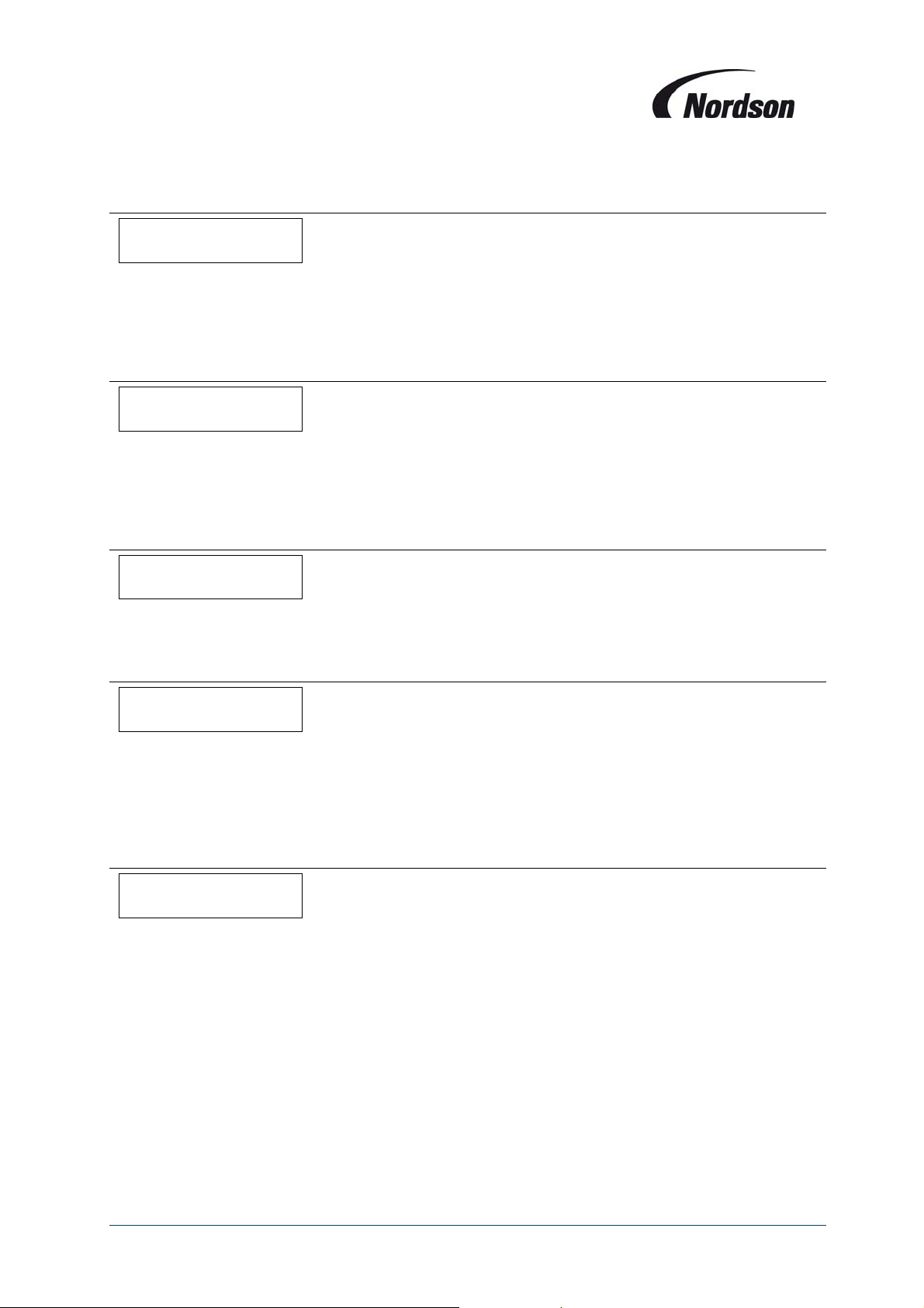
7.6. P06 Off Line cleaning Cycles
OFF_LINE_CLEAN_C
PO6_____XX_CYCLES
Once the fan set is switched off, Off Line Cleaning is initiated and completes the number of cycles
selected here. You can choose anything between 0 and 15 cycles. If the setting is “0”, Off Line Cleaning
is switched off.
7.7. P07 Star/Triangle switch over Time
ST_TR_SW_TIME___
P07______XXX_SEC
After the fan set is switched on, outputs K1 (mains contactors) and K3 (star contactors) are activated.
At the end of the star/triangle switch-over time, output K3 (star contactor) is switched off, and output
K2 (triangle contactor) is activated with a delay of approximately 0,5 seconds.
7.8. P09 Cleaning Pulse interval 1
PULSE_INTERVAL_1
P09______XXX_SEC
Cleaning Pulse interval is the time in seconds between cleaning pulses when cleaning is operational.
7.9. P12 Cleaning valve Pulse time
CLEAN_PULSE_TIME
P12_______XXX_MS
The pulse time for the cleaning valves is the time for which the solenoids are energised each pulse.
Factory default setting is 100 milliseconds – this is suitable for most Afterfilter types however please
refer to the specific installation and operation manual for your unit type to verify the correct pulse time
and adjust this parameter if required.
7.10. P15 display Language
DISPLAY_LANG_____
P15_______ENGLISH
The display text can be output in eight different languages. The default language is English, but you can
also choose one of following languages: German, French, Dutch, Italian, Spanish, Danish, and
Swedish. The set language will be used in all menu’s and modes.
20
Page 21
Installation, Operation and Maintenance Manual
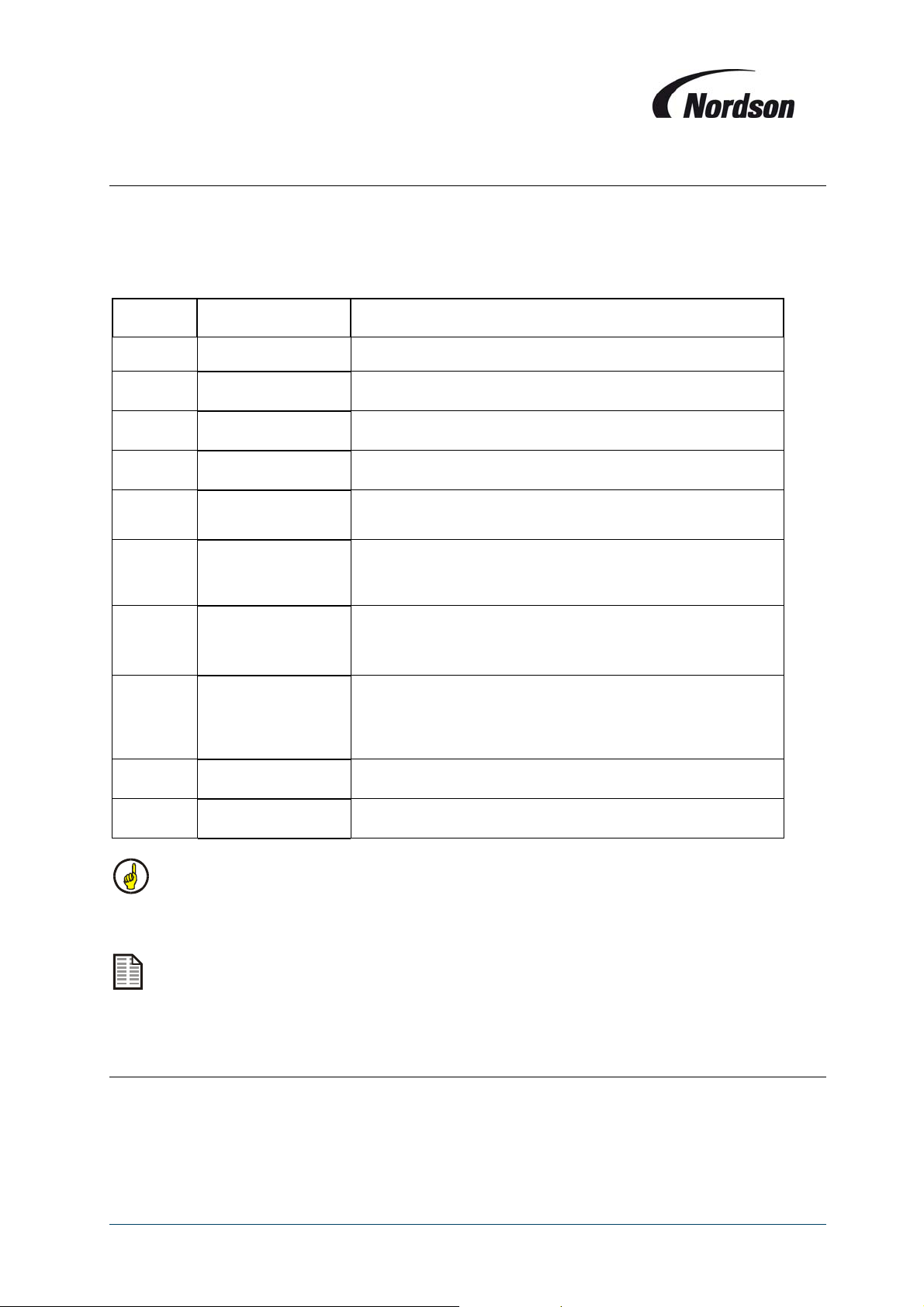
7.11. P17 Function of Input I1 (terminals 26-28)
These terminals allow an external volt free contact to be used to signal an input to the TCB.
The contact should be a normally closed contact, so an input signal is generated when the contact
opens.
(These terminals are supplied bridged).
Parameter
value
0
1
2
3
4
5
6
7
8
9
INPUT_FUNCT_I1__
P17_0__NO_FUNCT
INPUT_FUNCT_I1__
P17_1__ALARM.
INPUT_FUNCT_I1__
P17_2_EXT_CLEA_1
INPUT_FUNCT_I1__
P17_3_EXT_CLEA_2
INPUT_FUNCT_I1__
P17_4_STOP_CLEAN
INPUT_FUNCT_I1__
P17_5_URG_CLE_ST
INPUT_FUNCT_I1__
P17_6_STOP_ALL_
INPUT_FUNCT_I1__
P17_7_EMERG_STOP
INPUT_FUNCT_I1__
P17_8_CONF_AL_O1
INPUT_FUNCT_I1__
P17_9_CONF_AL_O2
Display Description
Input I1 or I2 has no function
When contact opens on Input, The system will give an Alarm
message
When contact opens on Input, cleaning is activated with interval
1. Cleaning will be activated until the contact is closed
When contact opens on Input, cleaning is activated with interval
2. Cleaning will be activated until the contact is closed
When contact opens on Input, cleaning remains active until a full
cleaning cycle is completed. When the contact closes again the
cleaning will not start again based on this input.
When contact opens on Input, Cleaning stops immediately and
the valve number of the last activated valve is stored. When the
contact closes again the cleaning will not start again based on
this input.
When contact opens on Input, Fan and Cleaning stops
immediately, the valve number of the last activated valve is
stored. When the contact closes again the fan will restart again
but the cleaning will not start again based on this input.
When contact opens on Input, Fan and Cleaning stops
immediately, the valve number of the last activated valve is
stored. The system will also generate an Alarm message. When
the contact closes again the fan will NOT restart again and also
the cleaning will NOT start again based on this input.
When contact opens on Input I1, the Alarm messages of Output
O1 is cleared/confirmed
When contact opens on Input I2, the Alarm messages of Optional
Output O2 is cleared/confirmed
When the cleaning stops using input signal option 4, 5, 6 or 7, it will not restart when the input
contact closes again, but only when the differential pressure measurement or a different input
signal causes a restart.
Input functions 2 – 6 and 7 & 8 are not available when the TCB is used to operate several fans
in ECB mode.
7.12. P18 Function of Input I2 (terminals 27-28)
These terminals provide the facility for a second programmable input. Setting options and function as
for I1 - See chapter 7.11.
21
Page 22
Installation, Operation and Maintenance Manual
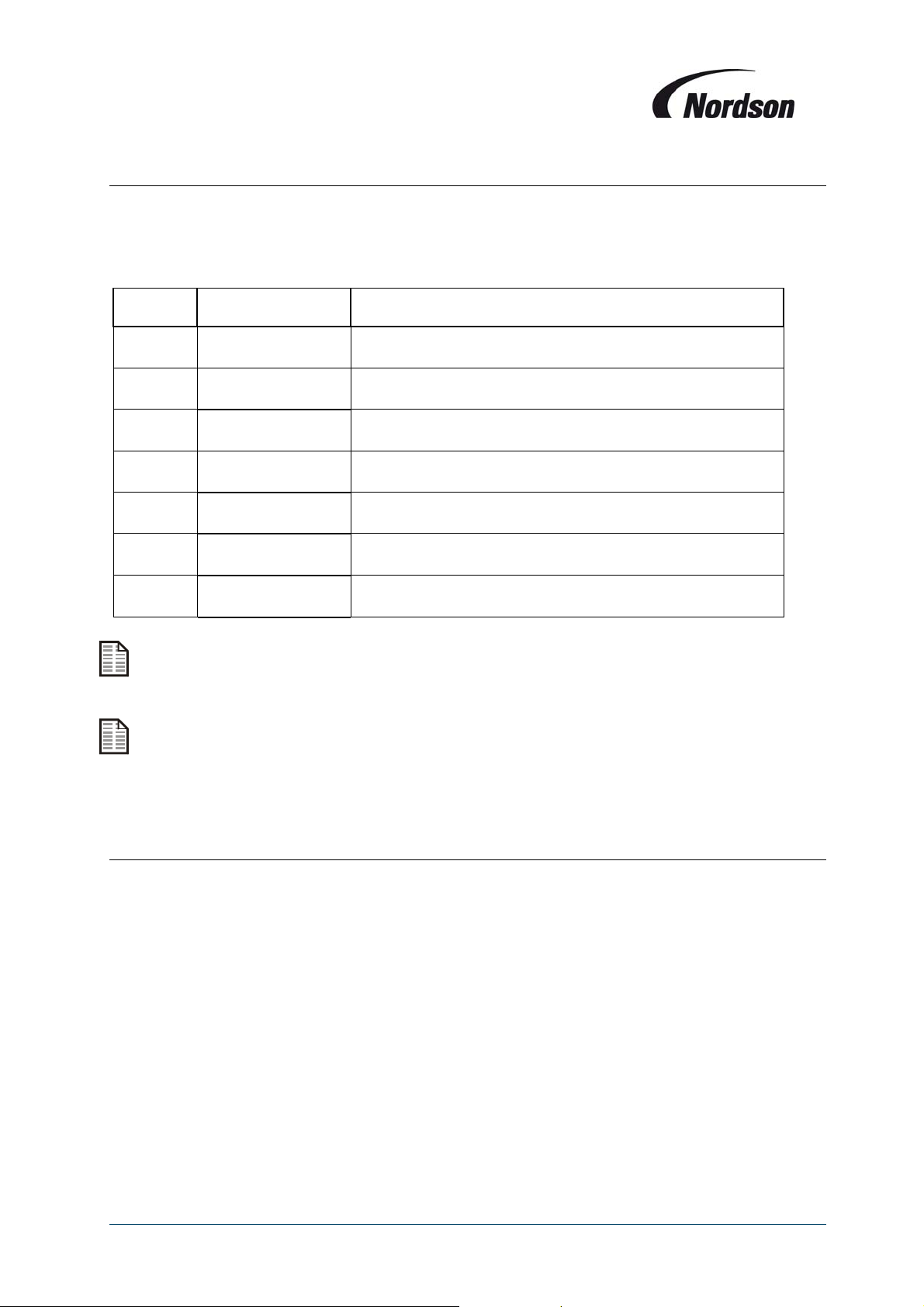
7.13. P19 Function of output relay O1 (Relay contact cleaning on / terminals 10-11)
A programmable output (volt free relay) is available at terminals 10 and 11 – the contact is normally
open. This can be programmed to close under a number of different conditions as detailed in the table
below.
Parameter
value
0
1
2
3
4
5
6
OUTPUT_FUNCT_O1_
P19_0__NO_FUNCT
OUTPUT_FUNCT_O1_
P19_1_CLEAN_ON__
OUTPUT_FUNCT_O1_
P19_2_FAN_ON
OUTPUT_FUNCT_O1_
P19_3_FAN_ON+__
OUTPUT_FUNCT_O1_
P19_4_DP_MAX_AL
OUTPUT_FUNCT_O1_
P19_5_LOW_PRE_AL
OUTPUT_FUNCT_O1_
P19_6_FAN_ALARM
Display Description
Output O1 or O2 has no function
Output relay is activated (Contacts closed) when cleaning is
active
Output relay is activated (Contacts closed) when fan is running
Output relay is activated (Contacts closed) when fan is running or
(off line) cleaning is active
Output relay is activated (Contacts closed) when Delta P Max
Alarm is active
Output relay is activated (Contacts closed) when Low Pressure
Alarm is active
Output relay is activated (Contacts closed) when Fan Alarm is
active
Alarm communication: These Alarm output relays stay active, it will only be de-activated by a
confirmation of the alarm by the ENTER button or remotely by a signal on Input I1 or I2.
These output functions are not available when the TCB is used to operate several fans in ECB
mode. (The relays are then used to power the fan contactors for fans 4 and the working area
lighting circuit).
7.14. P20 Function of Optional output relay O2 (Relay contact start extracting equipment /
terminals 12-13)
If this option is supplied a second programmable output is available at terminals 12 and 13. Details and
possible setting options are as for O1 - See chapter 7.13.
22
Page 23
Installation, Operation and Maintenance Manual
g
g
g
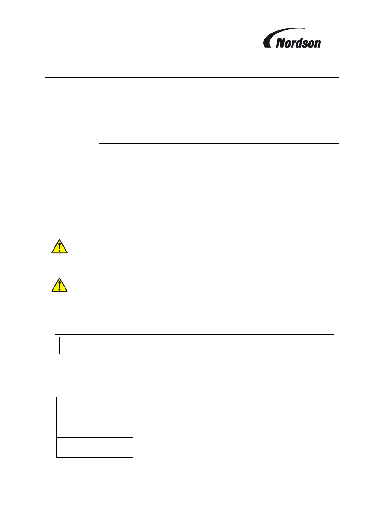
7.15. P22 Delta P Cleaning mode
Delta P Cleaning
mode
When off line cleaning is activated (option 3), make sure that parameter P06 (number of off-
line cleaning cycles) is not set to zero. Otherwise the unit will never start to pulse clean the
filter elements.
DP_CLEAN_MODE___
P22_0_CONT_CLEAN_
DP_CLEAN_MODE___
P22_1_STOP_&_GO
DP_CLEAN_MODE___
P22_2_STOP_&_END
DP_CLEAN_MODE___
P22_3_OFF_LINE_
Cleaning is not influenced by the differential pressure
measurement, but instead the valves will pulse
continuously. Differential pressure measurement and
monitorin
Cleaning is carried out based on the differential pressure
measurement. On a cleaning stop command, the valve
number of the last activated valve is stored. On the next
cleaning start command, cleaning begins with the valve
with the next hi
Cleaning is carried out based on the differential pressure
measurement. On a cleaning stop command, cleaning
remains active until a full cycle is completed. On the next
cleaning start command, the cleaning begins with the
first valve. This is used as default settin
Only differential pressure measurement and monitoring
are activated. All cleaning control functions based on
Delta P are deactivated. The only cleaning option is now
Off-Line Cleaning according the number of cycles
defined in parameter P06 or via an external command
on input I1 or I2.
are activated.
her valve number.
.
Multi fan ECB units operating with Explosive powder will only clean off-line and P22
parameter has no effect. A number of offline clean cycles must be set – otherwise cleaning
will not be initiated.
7.16. P26 Number of valves
NUMBER_VALVES___
P26___XXX_VALVES
Configuration of the number of valves connected to the controller. When the controller starts, all
valves are addressed and checked. If a valve has failed, it is skipped.
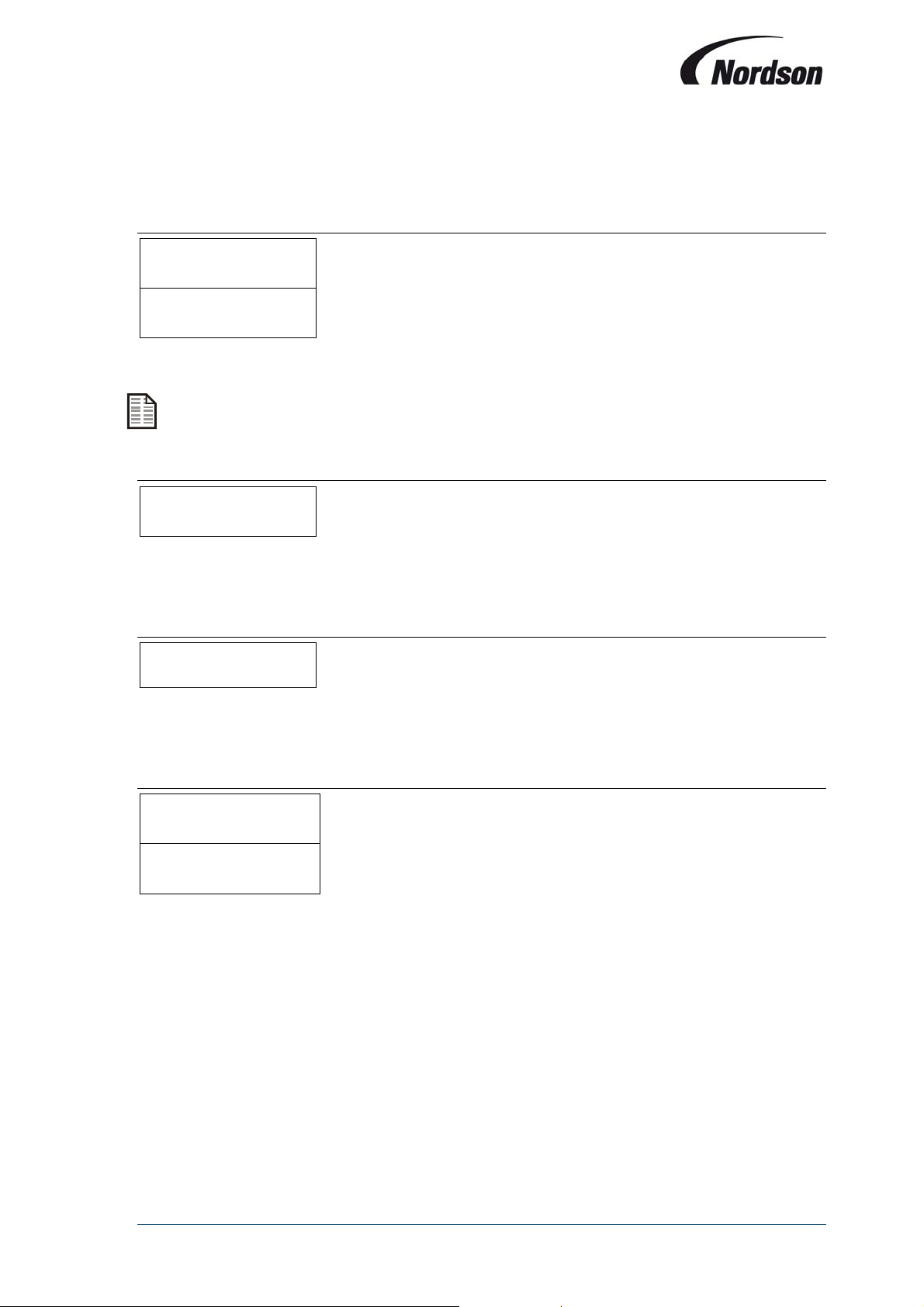
7.17. P40 Time/Date Display
T/D_DISPLAY_____
P40_A__AUTOMATIC
T/D_DISPLAY_____
P40_0S_____FIXED
T/D_DISPLAY_____
P40_0W_____FIXED
23
Page 24
Installation, Operation and Maintenance Manual
Setting of the current time of the system: Os = summer time, Ow = winter time, and A = Automatic
setting of summer- and wintertime depending on date and time settings in the system (Parameter
P41).
7.18. P41 Set Time and Date
DATE____________
P41___DD.MM.20YY
TIME____________
P41________HH:MM
Setting of the current time and date.
The time and date setting must be re-set after the battery has been removed / changed.
7.19. P44 Program Version
PROGRAM_VERSION_
P44_VXX.XX.XX/X
This parameter field shows the version of the software. The update and/or uploading of new
software can only be done by a Nordson representative.
7.20. P46 Active Pulse Display
ACTIVE_PULSE____
P46_VALVE__XX_YY
This parameter field shows the number of the valve that is last activated.
XX = Number of the module / YY = Number of the valve
7.21. P48 Test Display
TEST_CONTROLLER_
P48______RUNNING
TEST_CONTROLLER_
P48__________END
During this test, all LED’s on the control panel will light up for 10 seconds to be able to detect
defective LED’s.
24
Page 25
Installation, Operation and Maintenance Manual
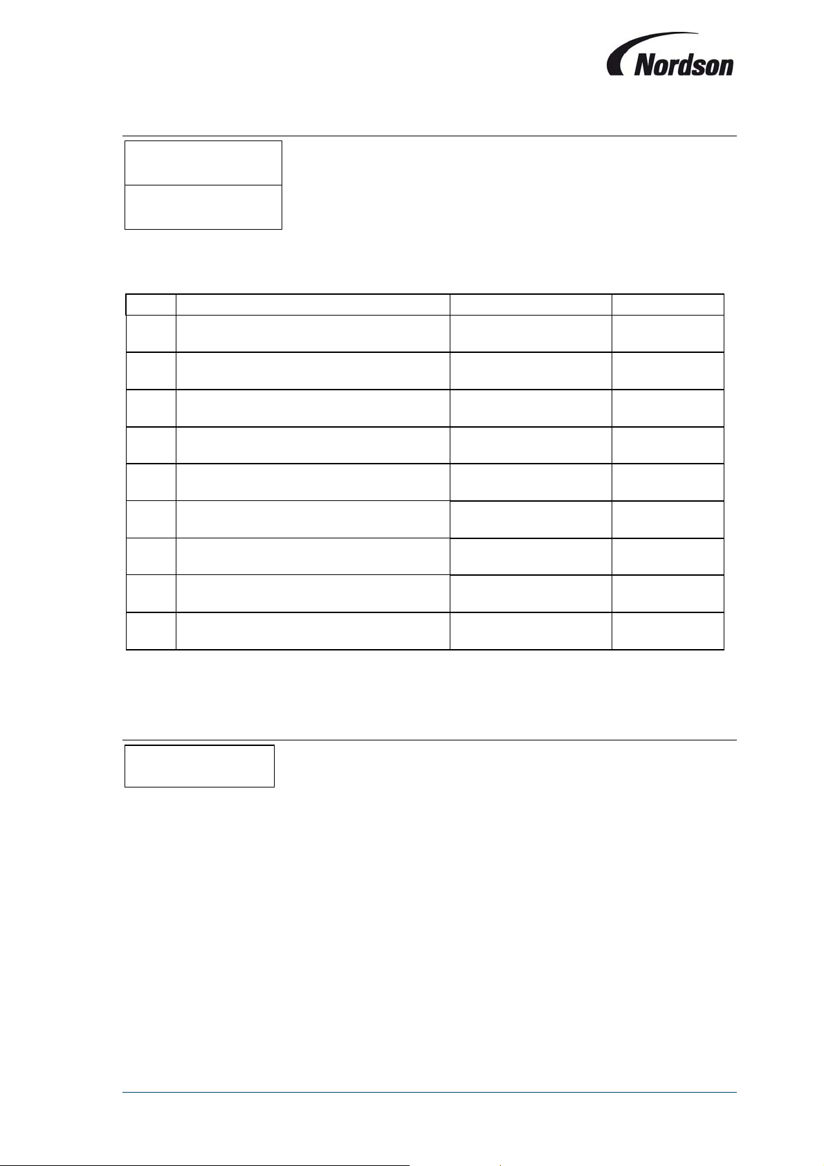
7.22. P50 Back To Factory Settings
FACTORY_SETTINGS
P50__________YES
FACTORY_SETTINGS
P50______CONFIRM
With this parameter the system will reset all the parameters as described in the next table to default
factory settings.
Code Description Display line Factory settings
P02 Delta P Min
P03 Delta P Max
P04 Delta P Max Alarm
P05 Low Pressure Alarm
P06 Off line Cleaning cycles
P07 Star/Triangle switch over time
P09 Cleaning Pulse interval 1
P12 Cleaning valve Pulse time
P22 Delta P Cleaning mode
The settings will be reset by pressing the enter button for more then 2 seconds. The system will ask
for a confirmation after which the enter button needs to be pressed again for more then 2 seconds.
DP_MIN__________
P02_____XXX_daPa
DP_MAX__________
P03_____XXX_daPa
DP_MAX_ALARM____
P04_____XXX_daPa
LOW_PRESS_ALARM_
P05_____XXX_daPa
OFF_LINE_CLEAN_C
P06____XX_CYCLES
ST_TR_SW_TIME___
P07______XXX_SEC
PULSE_INTERVAL_1
P09______XXX_SEC
CLEAN_PULSE_TIME
P12_______XXX_MS
DP_CLEAN_MODE___
P22_2_STOP_&_END
40 daPa
80 daPa
150 daPa
0 daPa
0
5 s
10 s
100 ms
Stop and End
7.23. M05 Total Operating Hours
TOTAL_OPERAT_H__
M05_xxxxxx_HOURS
Display of active operating hours (with running fan) of the control box since start-up.
25
Page 26
Installation, Operation and Maintenance Manual
)
y
8. ALARMMESSAGESANDFAULTLOCATION
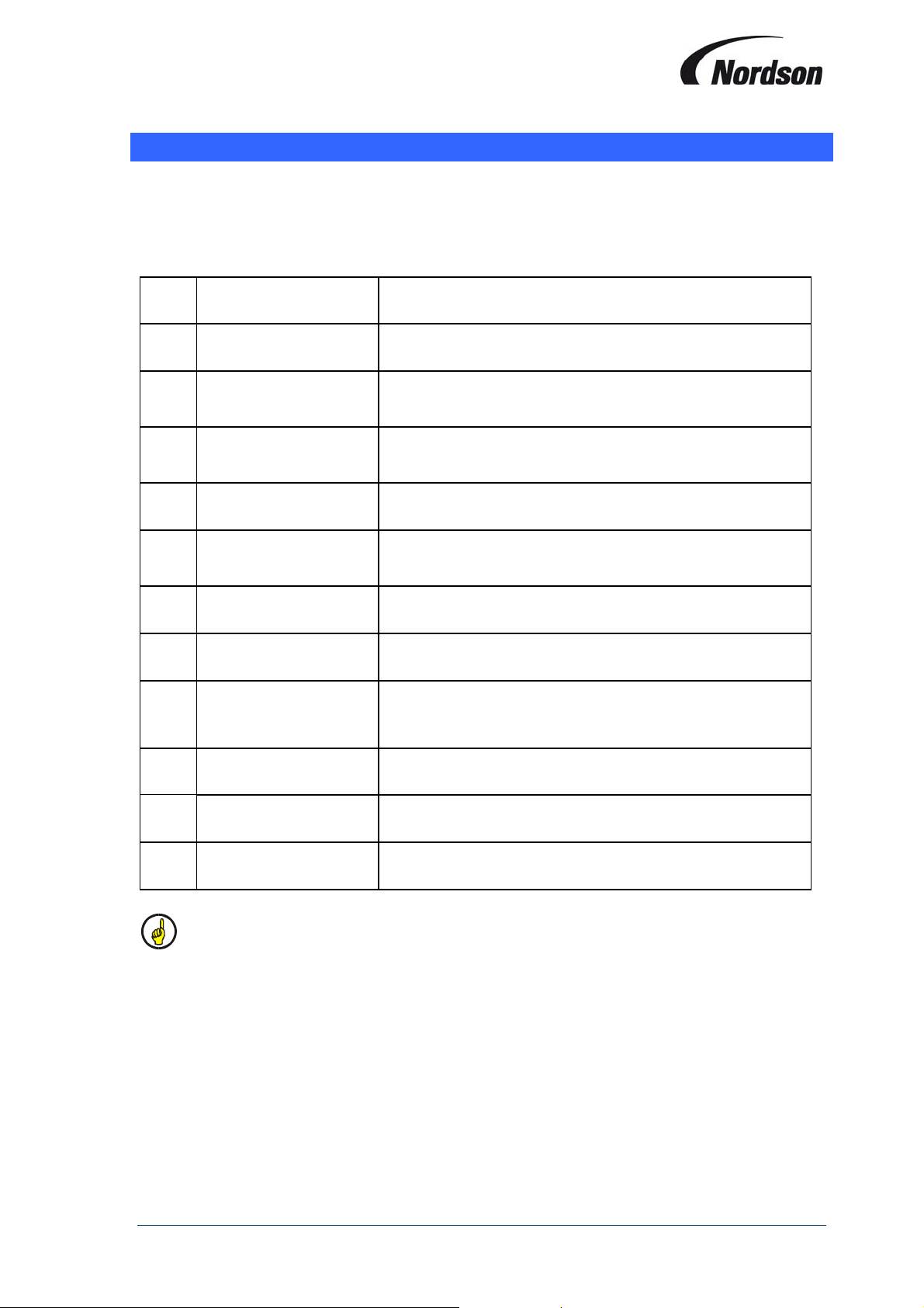
The TCB control box will display an alarm message when it detects a possibly dangerous situation
for the installation. When this happens first of all it is necessary to investigate the cause of the
alarm. After correcting the input signals to the control board, the alarm needs to be relieved by
pressing the ENTER button.
Alarm
code
Display line Alarm description
E01
E02
E05
E06
E07
E08
E09
E10
E11
_FAN_ALARM______
E01_HH:MM_______
_COMM_ALARM_____
E02__HH:MM_____
LOW_PRES_AL_daPA
E05__HH:MM__XXX_
DP_MAX_AL_(daPA)
E06__HH:MM__XXX_
_DATA_ALARM__
E07__HH:MM______
_ALARM_INPUT_I1_
E08__hh:mm______
_ALARM_INPUT_I2_
E09__hh:mm______
LOW BATTERY
/ SET TIME
E10__HH:MM______
DP SENSOR ALARM
E11__HH:MM______
Fan Alarm.
Fan overload contactor tripped.
Communication alarm
A bus component connected is not responding (e.g. slave
module, I/O Module
Low Pressure Alarm
After fan start the differential pressure is below the set value
P05
DP Max Alarm
The differential pressure is above the set value P04
Data alarm
Data has been lost. All parameter values must be checked
and corrected if necessar
Error message / Alarm on Input I1 (secondary filters)
Error message / Alarm on Input I2
Low battery for real time clock or incorrect time setting.
Wrong connection of Delta P if Delta P is smaller than 0
Inspect primary (cartridge) filters, possible overload/blocked
E12
E13
EMERG STOP
E12__HH:MM______
HIGH DP SYS.STOP
E13__HH:MM______
Emergency stop of fan set and cleaning based on input
signal option 7 (see chapter 7.11)
After an off-line cleaning cycle of an ECB unit the pressure
drop has remained above the set DP Max level.
When any of the above alarms are active it will be impossible to start up the fan set. Unless
the alarm triggers a shutdown, the fan set will keep running when it was already activated
before the alarm.
26
Page 27
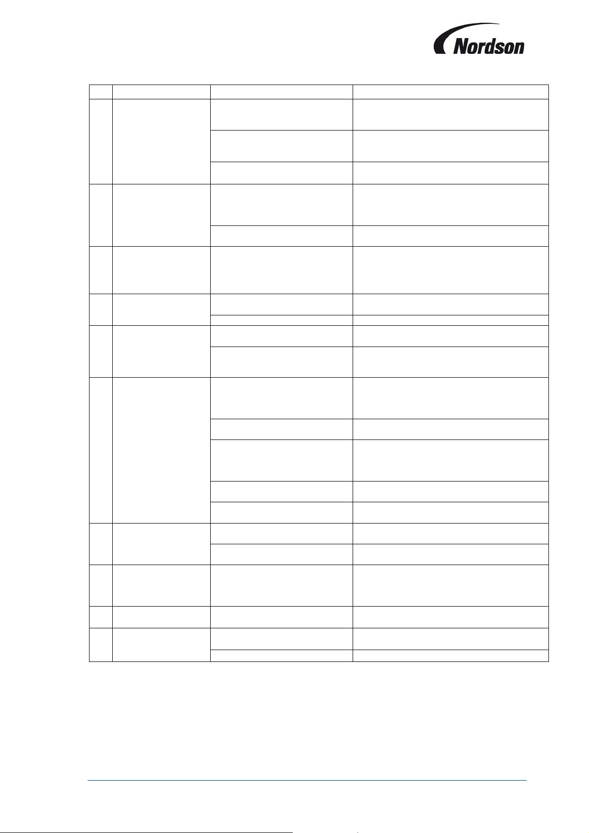
Installation, Operation and Maintenance Manual
–
Symptom Possible cause Action
Green power-on LED
A
on module PCB not
illuminated.
Fan does not start
and LED ‘Fan on’
B
(item 7 fig. 1) is not
illuminated.
The control board is
operational, but the
C
fan does not start. No
failure is indicated.
The automatic circuit
D
breaker switches off
while the fan starts-up
The fan only works in
star operation when
E
the unit is switched
on; in triangle the fan
stops.
No cleaning pulses
but the LED ‘Pulse
F
cleaning’ (item 7, fig.
1) is blinking.
Solenoid valve failure
Diaphragm valve failure
G No off-line cleaning.
Off-line cleaning cycles set to ‘0’
Incorrect/gaps in
H
valve firing sequence.
I
Incorrect reading.
Incorrect 4-20mA
J
output.
Electrical supply fault.
Fuse on PCB module blown.
Internal controller failure.
Main switch on control box open Turn main switch to ON-position.
Electrical supply fault
Blown fuse
Delay time between star and
triangle is too short.
Incorrect fan overload setting Check fan overload setting
Contactor K2 defective.
Incorrect wiring to fan Check wiring from TCB to fan
Low supply voltage.
Lack of compressed air for
cleaning.
Solenoid valves not connected
correctly.
Off-line cleaning not activated.
Solenoid valves not connected
correctly.
Loose connections on
pressure lines.
External circuit resistance too
high.
problem
Check supply circuit for proper voltage, fuses,
circuit breakers etc. Replace as required.
Check wiring connections and replace fuse
with correct type (refer to chapter 11:
Maintenance).
Replace PCB.
Check supply circuit for proper voltage, fuses,
circuit breakers etc. Replace as required.
Check the circuit and change fuse F3 (see
wiring diagram supplied with TCB).
Increase change-over time (see chapter 7.7)
Change contactor K2 (see wiring diagram
supplied with TCB)
Check supply voltage (a low voltage will not
open valves but may operate LED’s normally).
Increase compressed air pressure for manifold
to 6
7 bar.
Check connections to solenoid valves in
enclosure or external valve enclosures. Ensure
connection plug is correctly engaged in PCB
socket.
Check for proper valve action and repair or
replace if necessary.
Check for proper valve action and repair or
replace if necessary
Set up controller to off-line cleaning mode
(refer to chapter 7.15).
Increase number of off-line cleaning cycles
(refer to chapter 7.6)
Check connections to solenoid valves in
enclosure or external valve enclosures. Ensure
connection plug is correctly engaged in PCB
socket.
Check connections for leaks.
Reduce external circuit resistance
(recommended range 150-250).
Refer to section I of Fault Location Table.
27
Page 28
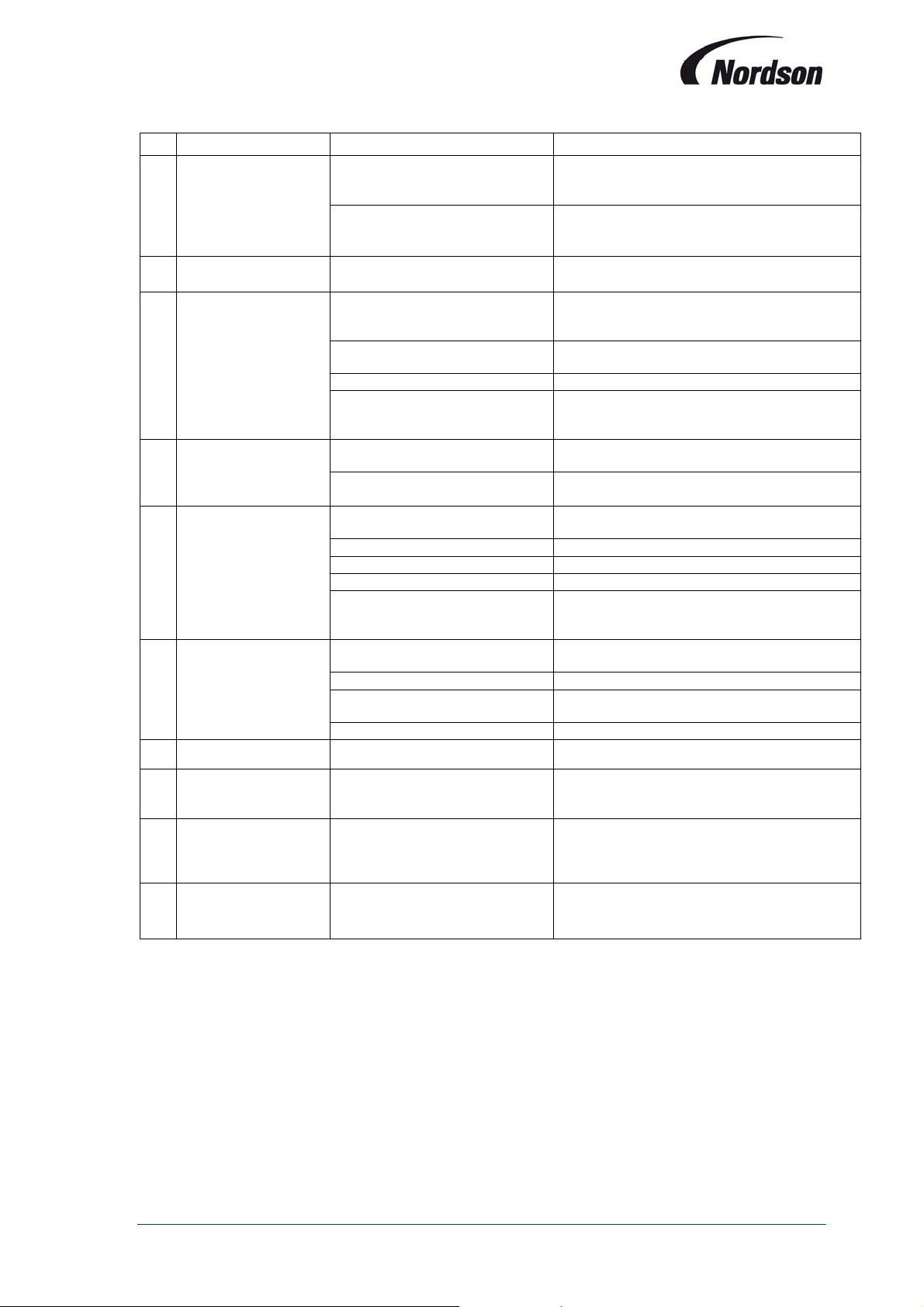
Installation, Operation and Maintenance Manual
–
Symptom Possible cause Action
Check compressor capacity. Check pulse
K Weak pulses.
LED bar graph
L
pulsing
M E 01: Fan alarm
Faulty motor Repair or replace as required.
E 02: Communication
N
alarm
E 05: Low pressure
O
alarm
E 06: DeltaP max
P
alarm
Low compressed air pressure
End of useful filter element life Replace filter elements as a complete set
Q E 07: Data alarm Data lost from memory Check all parameters and correct if necessary.
E 10: Low battery /
R
Check Time
E 11: Negative
S
DeltaP measurement
Air supply inadequate.
Supply voltage too low.
is below -20 daPa
Lack of proper system flow or
open access to ambient
System airflow exceeds the rated
flow
Automatic circuit breaker is OK
but a missing connection
between terminal 33-34
RS-485 bus link between system
components not functioning.
Slave modules not responding
Faulty parameter settings Check parameter settings (see chapter 7.5).
problem
Fan motor fault Check operation of fan motor
Ducting restricted or blocked Check ducting system
Filter elements damaged
Faulty parameter settings Check parameter settings (see chapter 7.4)
problem
Low battery for real-time clock /
incorrect clock settings
Pneumatic tubing connections
incorrect
interval – air pressure in manifold should
return to required value before next pulse.
Check supply voltage and connections to
Control box.
Reverse pressure drop tubing connections
Close open hopper discharge or other
openings. Do not attempt to run without inlet
ducting attached.
Adjust inlet or outlet damper(s)
Check and repair the connection
Check bus link wiring.
Check mode and module switch settings on
slave modules.
Refer to section I of Fault Location Table.
Check condition of all filter elements. If
necessary replace all filter elements at the
same time.
Refer to section I of Fault Location Table.
Check reverse-jet pulsing system. Increase
manifold pressure to 6
Check / Replace battery on front PCB module
(see picture in chapter 9). Correct type is
CR2032. Re-set time and date.
Reverse the pressure drop tubing connections.
If a safety filter (Micrafilter) is present it has to
be in the dirty air plenum tubing (both tubes for
explosive powder applications).
7 bar.
E13 : High DP after
T
ECB clean cycle
High DP on ECB unit after
cleaning
Refer to section P (E06 high DeltaP) above.
28
Page 29
Installation, Operation and Maintenance Manual
9. MAINTENANCE
In general the TCB control box does not require any maintenance. There are some items however
that need to be checked on a regular basis:
In-line Micrafilters in the air lines: when these are very dirty, there will be a pressure drop
over them, making the differential pressure measurement over the elements unreliable.
Air lines and cable glands to and from control box should be checked for damage and/or
tightness. If these become loose, the values shown on the display may not be accurate,
and possibly powder or moisture will be able to enter the enclosure causing damages and
possible short-circuits.
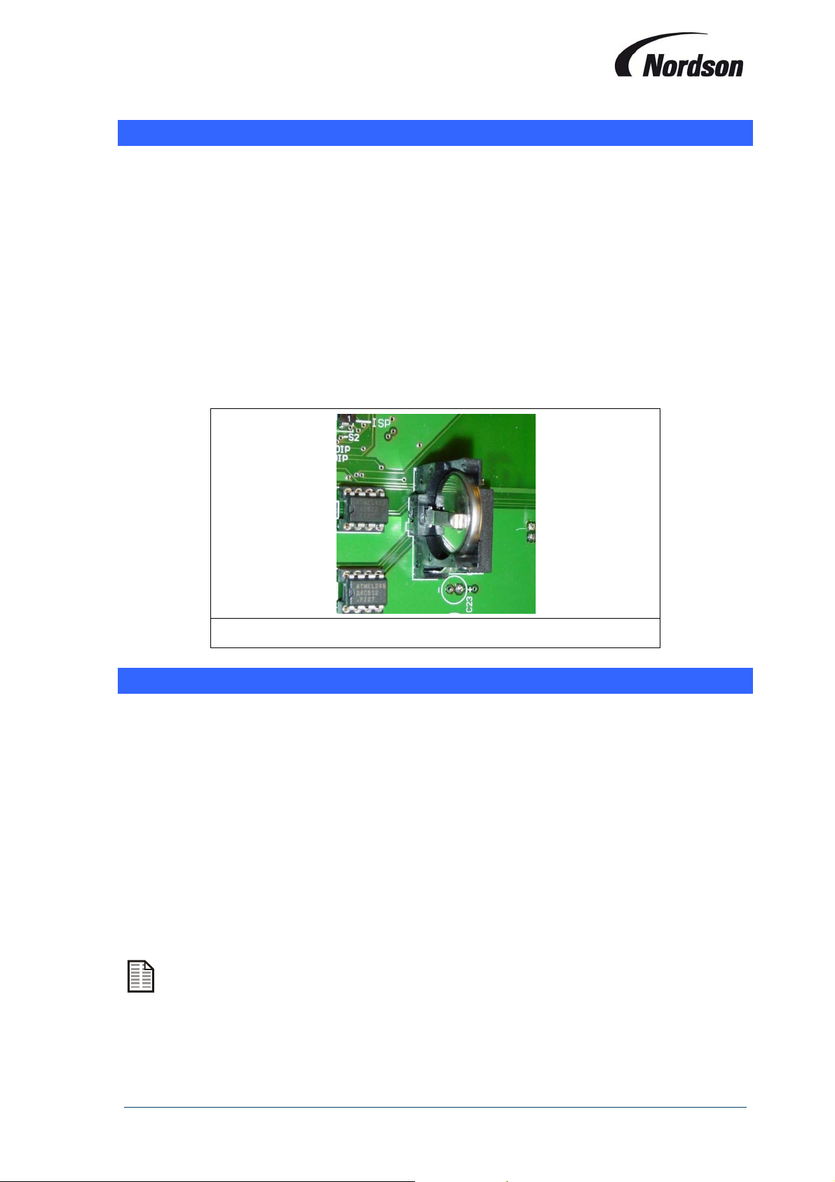
The clock on the front PCB has a CR 2032 battery. This battery will deplete over time and
needs to be changed as soon as the alarm message is displayed. In order to do this, the
cover over the front PCB needs to be removed first. Make sure to mount the battery with
the ‘+’ side facing to the right of the PCB.
Re-set the time and date after replacing the battery.
Figure 4: Display PCB battery
10. OPTIONSANDFEATURES
In addition to the features already described, the Total Control Board has some extra options and
settings built-in to provide additional functions and data recording / information retrieval capabilities.
These following options can only be accessed and installed by a Nordson representative, so please
consult your local Nordson representative for more information.
Forced cleaning time: initiates a forced cleaning cycle at a specified time interval.
Fan run-on time: fan set remains activated during a certain period after system is switched
off.
Optional input signal: possibility to initiate for example an alarm to stop cleaning cycle.
Optional output signal: possibility to start for example a rotary airlock on off-line cleaning.
DeltaP sensor type: possibility to measure DeltaP over filter elements by a 4-20 mA
pressure transducer.
Thermistor module for fan motor protection.
4-20mA Output proportional to measured pressure drop.
The options mentioned above can also cause alarm messages to be displayed on the TCB.
Relieving the alarm is done in the same way by pressing the ENTER button after correcting
the input to the control board.
29
Page 30
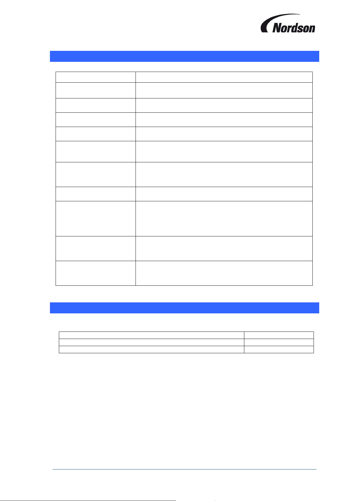
Installation, Operation and Maintenance Manual
11. SPECIFICATIONS
Printed Circuit Boards Data
Supply voltage 24 V (AC or DC): -0%/+10%
Back-Up Battery CR 2032. 3 Volts
Bus RS-485 bus link with 9600 Baud bit rate
Inputs Signal Potential free contacts only
Differential Pressure
Transducer
Signal output (Option) 4-20mA output proportional to differential pressure of
Relay outputs Max. 2 A, 250 VAC or 1 A, 30 VDC
Valve outputs 24 V DC
Fuse I/O Module T 2,0 A, 250 VAC, 5 x 20 mm
Dimensions Display PCB. 258 x 175 x 65 mm
0-500 daPa, Display Range 0-500 daPa. Accuracy - 2,5%
0 – 500 daPa
Single I/O module system - Max. 1,9 A
Slave I/O modules - Max. 1.0 A
Display – PTC Device.
I/O Module PCB 220 x 80 mm
(1 x 22W Valve per output)
(2 x 22W Valve per output)
12. SPAREPARTS
ITEM Nordson Part No.
TCB,DISPLAY,CONTROLLER,GEN5 A/F 7034116
TCB, I/O MODULE,GEN5 A/F 7034117
30
Page 31
Installation, Operation and Maintenance Manual
13. ECDECLARATIONOFCONFORMITY
ACCORDING TO CE DIRECTIVE 2006/42/EC ANNEX II A
(FOR TRANSLATION PURPOSES)
DESCRIPTION: Afterfilter Gen 5 Total Control Board
FAMILY/MODELS: All variants and models
APPLICABLE DIRECTIVES: EC-Declaration of Conformity acc. to Article 10.1
of Directive 89/336/EEC and 73/23EEC (EMCDirective)
STANDARDS USED TO
VERIFY COMPLIANCE: 1. EN 6100-6-4:2001
EN 55011:1988 Gr.1 Kl. A
EN 61000-3-2:2001
EN 61000-3-3:1995 + A1:2001
2. EN 6100-6-4:2001
EN 6100-4-6:1996 + A1:2001
EN 6100-4-3:1996 + A1:1998 + A2:2001
EN 6100-4-4:1995 + A1:2001
EN 6100-4-5:1995 + A1:2001
EN 6100-4-11:1994 + A1:2000
EN 6100-4-2:1995 + A1:1998 + A2:2001
3. EWG 73/23
VDE 0160
VDE 0113 EN 60204 Teil 1 A1:2006
MARKING OF PRODUCT:
The equipment delivered is generally intended to be part of a powder coating system, and can
be operated on its own or in conjunction with other equipment. In order to be in full compliance
with the CE machinery directive and its amendments, the customer is obliged to respect the
applicable regulations for his powder coating system upon incorporation of the equipment in
the powder coating plant and before starting operation.
We hereby declare that the product specified conforms to the directives and standards
described above and that it has been provided with a CE label. Provided the product is
installed and operated in line with the Nordson manuals, its operation is safe.
Kai Flockenhaus
Manager Procurement & Process,
ICS
Europe (Industrial Coating Systems)
Nordson Deutschland GmbH
Date: 18/02/2015
31
 Loading...