

Page 1

Liquidyn P-Jet CT Jet Valve
Operating Manual
™
Electronic pdf les of Nordson EFD
manuals are also available at
nordsonefd.com
Page 2

Liquidyn P-Jet CT Jet Valve
You have selected a reliable, high-quality dispensing system from Nordson EFD, the world leader in uid
dispensing. The Liquidyn® P-Jet CT jet valve was designed specically for industrial dispensing and will
provide you with years of trouble-free, productive service.
This manual will help you maximize the usefulness of your Liquidyn P-Jet valve
Please spend a few minutes to become familiar with the controls and features. Follow our recommended
testing procedures. Review the helpful information we have included, which is based on more than
50years of industrial dispensing experience.
Most questions you will have are answered in this manual. However, if you need assistance, please do
not hesitate to contact EFD or your authorized EFD distributor. Detailed contact information is provided
on the last page of this document.
The Nordson EFD Pledge
Thank You!
You have just purchased the world’s nest precision dispensing equipment.
I want you to know that all of us at Nordson EFD value your business and will do everything in our power
to make you a satised customer.
If at any time you are not fully satised with our equipment or the support provided by your Nordson
EFD Product Application Specialist, please contact me personally at 800.556.3484 (US), 401.431.7000
(outside US), or [email protected].
I guarantee that we will resolve any problems to your satisfaction.
Thanks again for choosing Nordson EFD.
Srini Subramanian
Srini Subramanian, General Manager
2 nordsonefd.com [email protected] 800-556-3484 Sales and service of Nordson EFD dispensing systems are available worldwide.
Page 3

Liquidyn P-Jet CT Jet Valve
Contents
Contents ..........................................................................................................................................................................3
Introduction .....................................................................................................................................................................5
How the Valve Operates ..............................................................................................................................................5
How the Valve is Controlled .........................................................................................................................................5
Nordson EFD Product Safety Statement ........................................................................................................................6
Halogenated Hydrocarbon Solvent Hazards ...............................................................................................................7
High Pressure Fluids ....................................................................................................................................................7
Qualied Personnel ......................................................................................................................................................7
Intended Use ...............................................................................................................................................................8
Regulations and Approvals ..........................................................................................................................................8
Personal Safety ............................................................................................................................................................8
Fire Safety ....................................................................................................................................................................9
Preventive Maintenance ..............................................................................................................................................9
Important Disposable Component Safety Information ..............................................................................................10
Action in the Event of a Malfunction ..........................................................................................................................10
Disposal .....................................................................................................................................................................10
Equipment-Specic Safety Information .....................................................................................................................11
Specications ................................................................................................................................................................12
Operating Features ........................................................................................................................................................13
Installation .....................................................................................................................................................................14
Unpack the System Components ..............................................................................................................................14
Assemble the Valve (Initial Assembly) ........................................................................................................................15
Change the Fluid Body or Tappet (Optional) .............................................................................................................16
Install a Nozzle Heater (Optional) ...............................................................................................................................18
Mount the Valve .........................................................................................................................................................19
Connect Cables .........................................................................................................................................................20
Connect the Air Supply ..............................................................................................................................................21
Installation Example ...................................................................................................................................................22
Initial Startup ..............................................................................................................................................................23
Parameter Settings ....................................................................................................................................................24
Recommended Setup Adjustments ...........................................................................................................................25
Tappet Adjustment .....................................................................................................................................................26
Adjusting the Force Screw .....................................................................................................................................26
Adjusting the Stroke ...............................................................................................................................................27
Service ...........................................................................................................................................................................28
Recommended Maintenance Schedule.....................................................................................................................28
Valve Cleaning ...........................................................................................................................................................28
Shut Down the System ..........................................................................................................................................29
Disassemble the Valve ...........................................................................................................................................29
Clean the Valve Components .................................................................................................................................30
Assemble the Valve (After Cleaning) ......................................................................................................................31
Continued on next page
3nordsonefd.com [email protected] 800-556-3484 Sales and service of Nordson EFD dispensing systems are available worldwide.
Page 4

Liquidyn P-Jet CT Jet Valve
Contents (continued)
Replacement Parts ........................................................................................................................................................33
Valve Components .....................................................................................................................................................33
Nozzles and Nozzle Retaining Nuts ...........................................................................................................................34
Syringe Barrels and Accessories ...............................................................................................................................35
Material Supply Tubing Components ........................................................................................................................36
Steel Tubing Connectors ........................................................................................................................................36
Plastic Tubing Connectors .....................................................................................................................................36
Tubing .....................................................................................................................................................................36
Accessories ...............................................................................................................................................................37
Quick-Release Valve Mounting Components ........................................................................................................37
Precision Pressure Regulator .................................................................................................................................37
Nozzle Heaters .......................................................................................................................................................38
Tools and Supplies .....................................................................................................................................................39
Technical Data ...............................................................................................................................................................40
Dimensions ................................................................................................................................................................40
M8 Valve Cable Pin Positions ....................................................................................................................................40
Appendix A, About Non-Contact Dispensing................................................................................................................41
Appendix B, P-Jet CT Valve Interface Overview ...........................................................................................................42
Electrical Control........................................................................................................................................................42
Optional Nozzle Heater Control .................................................................................................................................43
Pneumatic Control .....................................................................................................................................................44
Valve Conguration Options ......................................................................................................................................44
4 nordsonefd.com [email protected] 800-556-3484 Sales and service of Nordson EFD dispensing systems are available worldwide.
Page 5

Introduction
The Liquidyn P-Jet CT pneumatic micro-dispensing jet valve is
designed for the non-contact dispensing of low- to medium-viscosity
materials, including oils, greases, glues, ux, and lled products.
Valve Speed and Deposit Size
The valve can produce micro-deposits as small as 3 nL at dispensing
frequencies of up to 280Hz, for a faster production process. The valve
can also dispense larger material volumes.
Modular, Exchangeable Components
Because the material-carrying components are separate from the
actuator, dispensing tappets and nozzles can be quickly and easily
exchanged, allowing the valve to efciently dispense highly abrasive
mediums as well. The exchangeable design also makes material-type
changeout and component replacement fast and easy.
The Liquidyn P-Jet CT valve is congurable. Many choices for the
material supply components and the nozzle are available, including an
optional nozzle heater.
Liquidyn P-Jet CT Jet Valve
Liquidyn P-Jet CT micro-dispensing valve
with a syringe barrel material supply
How the Valve Operates
The Liquidyn P-Jet CT valve is electro-pneumatically operated by a low
voltage, adjustable pulse signal that can start at 2 ms. The dispensing
tappet remains open until the trigger signal ends. The valve is normally
closed (NC) when idle, thus reducing the possibility of unintended uid
release upon power off.
How the Valve is Controlled
The valve can be operated using a Nordson EFD Liquidyn valve
controller or directly by the customer via a 24V input using a customersupplied controller or a programmable logic controller (PLC).
The Liquidyn V200 controller can be used
to control the operation of the Liquidyn
P-Jet CT valve
5nordsonefd.com [email protected] 800-556-3484 Sales and service of Nordson EFD dispensing systems are available worldwide.
Page 6

Liquidyn P-Jet CT Jet Valve
Nordson EFD Product Safety Statement
WARNING
The safety message that follows has a WARNING level hazard.
Failure to comply could result in death or serious injury.
ELECTRIC SHOCK
Risk of electric shock. Disconnect power before removing covers and / or disconnect, lock out, and
tag switches before servicing electrical equipment. If you receive even a slight electrical shock, shut
down all equipment immediately. Do not restart the equipment until the problem has been identied
and corrected.
CAUTION
The safety messages that follow have a CAUTION level hazard.
Failure to comply may result in minor or moderate injury.
READ MANUAL
Read manual for proper use of this equipment. Follow all safety instructions. Task- and equipmentspecic warnings, cautions, and instructions are included in equipment documentation where
appropriate. Make sure these instructions and all other equipment documents are accessible to
persons operating or servicing equipment.
MAXIMUM AIR PRESSURE
Unless otherwise noted in the product manual, the maximum air input pressure is 7.0 bar (100 psi).
Excessive air input pressure may damage the equipment. Air input pressure is intended to be applied
through an external air pressure regulator rated for 0 to 7.0 bar (0 to 100 psi).
RELEASE PRESSURE
Release hydraulic and pneumatic pressure before opening, adjusting, or servicing pressurized
systems or components.
BURNS
Hot surfaces! Avoid contact with the hot metal surfaces of heated components. If contact can not be
avoided, wear heat-protective gloves and clothing when working around heated equipment. Failure
to avoid contact with hot metal surfaces can result in personal injury.
6 nordsonefd.com [email protected] 800-556-3484 Sales and service of Nordson EFD dispensing systems are available worldwide.
Page 7

Liquidyn P-Jet CT Jet Valve
Nordson EFD Product Safety Statement (continued)
Halogenated Hydrocarbon Solvent Hazards
Do not use halogenated hydrocarbon solvents in a pressurized system that contains aluminum components.
Under pressure, these solvents can react with aluminum and explode, causing injury, death, or property damage.
Halogenated hydrocarbon solvents contain one or more of the following elements.
Element Symbol Prefix
Fluorine F “Fluoro-”
Chlorine Cl “Chloro-”
Bromine Br “Bromo-”
Iodine I “Iodo-”
Check the Safety Data Sheet (SDS) or contact your material supplier for more information. If you must use
halogenated hydrocarbon solvents, contact your EFD representative for compatible EFD components.
High Pressure Fluids
High pressure uids, unless they are safely contained, are extremely hazardous. Always release uid pressure before
adjusting or servicing high pressure equipment. A jet of high pressure uid can cut like a knife and cause serious
bodily injury, amputation, or death. Fluids penetrating the skin can also cause toxic poisoning.
WARNING
Any injury caused by high pressure liquid can be serious. If you are injured or even suspect an injury:
• Go to an emergency room immediately.
• Tell the doctor that you suspect an injection injury.
• Show the doctor the following note.
• Tell the doctor what kind of material you were dispensing.
Medical Alert — Airless Spray Wounds: Note to Physician
Injection in the skin is a serious traumatic injury. It is important to treat the injury surgically as soon as possible. Do
not delay treatment to research toxicity. Toxicity is a concern with some exotic coatings injected directly into the
bloodstream.
Qualified Personnel
Equipment owners are responsible for making sure that EFD equipment is installed, operated, and serviced by
qualied personnel. Qualied personnel are those employees or contractors who are trained to safely perform
their assigned tasks. They are familiar with all relevant safety rules and regulations and are physically capable of
performing their assigned tasks.
7nordsonefd.com [email protected] 800-556-3484 Sales and service of Nordson EFD dispensing systems are available worldwide.
Page 8

Liquidyn P-Jet CT Jet Valve
Nordson EFD Product Safety Statement (continued)
Intended Use
Use of EFD equipment in ways other than those described in the documentation supplied with the equipment may
result in injury to persons or damage to property. Some examples of unintended use of equipment include:
• Using incompatible materials.
• Making unauthorized modications.
• Removing or bypassing safety guards or interlocks.
• Using incompatible or damaged parts.
• Using unapproved auxiliary equipment.
• Operating equipment in excess of maximum ratings.
• Operating equipment in an explosive atmosphere.
Regulations and Approvals
Make sure all equipment is rated and approved for the environment in which it is used. Any approvals obtained for
Nordson EFD equipment will be voided if instructions for installation, operation, and service are not followed. If the
equipment is used in a manner not specied by Nordson EFD, the protection provided by the equipment may be
impaired.
Personal Safety
To prevent injury, follow these instructions:
• Do not operate or service equipment unless you are qualied.
• Do not operate equipment unless safety guards, doors, and covers are intact and automatic interlocks are
operating properly. Do not bypass or disarm any safety devices.
• Keep clear of moving equipment. Before adjusting or servicing moving equipment, shut off the power supply
and wait until the equipment comes to a complete stop. Lock out power and secure the equipment to prevent
unexpected movement.
• Make sure spray areas and other work areas are adequately ventilated.
• When using a syringe barrel, always keep the dispensing end of the tip pointing towards the work and away
from the body or face. Store syringe barrels with the tip pointing down when they are not in use.
• Obtain and read the Safety Data Sheet (SDS) for all materials used. Follow the manufacturer’s instructions for
safe handling and use of materials and use recommended personal protection devices.
• Be aware of less-obvious dangers in the workplace that often cannot be completely eliminated, such as hot
surfaces, sharp edges, energized electrical circuits, and moving parts that cannot be enclosed or otherwise
guarded for practical reasons.
• Know where emergency stop buttons, shutoff valves, and re extinguishers are located.
• Wear hearing protection to protect against hearing loss that can be caused by exposure to vacuum exhaust port
noise over long periods of time.
8 nordsonefd.com [email protected] 800-556-3484 Sales and service of Nordson EFD dispensing systems are available worldwide.
Page 9

Liquidyn P-Jet CT Jet Valve
Nordson EFD Product Safety Statement (continued)
Fire Safety
To prevent a re or explosion, follow these instructions:
• Shut down all equipment immediately if you notice static sparking or arcing. Do not restart the equipment until
the cause has been identied and corrected.
• Do not smoke, weld, grind, or use open ames where ammable materials are being used or stored.
• Do not heat materials to temperatures above those recommended by the manufacturer. Make sure heat
monitoring and limiting devices are working properly.
• Provide adequate ventilation to prevent dangerous concentrations of volatile particles or vapors. Refer to local
codes or the SDS for guidance.
• Do not disconnect live electrical circuits when working with ammable materials. Shut off power at a disconnect
switch rst to prevent sparking.
• Know where emergency stop buttons, shutoff valves, and re extinguishers are located.
Preventive Maintenance
As part of maintaining continuous trouble-free use of this product, Nordson EFD recommends the following simple
preventive maintenance checks:
• Periodically inspect tube-to-tting connections for proper t. Secure as necessary.
• Check tubing for cracks and contamination. Replace tubing as necessary.
• Check all wiring connections for looseness. Tighten as necessary.
• Clean: If a front panel requires cleaning, use a clean, soft, damp rag with a mild detergent cleaner. DO NOT USE
strong solvents (MEK, acetone, THF, etc.) as they will damage the front panel material.
• Maintain: Use only a clean, dry air supply to the unit. The equipment does not require any other regular
maintenance.
• Test: Verify the operation of features and the performance of equipment using the appropriate sections of this
manual. Return faulty or defective units to Nordson EFD for replacement.
• Use only replacement parts that are designed for use with the original equipment. Contact your Nordson EFD
representative for information and advice.
9nordsonefd.com [email protected] 800-556-3484 Sales and service of Nordson EFD dispensing systems are available worldwide.
Page 10

Liquidyn P-Jet CT Jet Valve
Nordson EFD Product Safety Statement (continued)
Important Disposable Component Safety Information
All Nordson EFD disposable components, including syringe barrels, cartridges, pistons, tip caps, end caps,
and dispense tips, are precision engineered for one-time use. Attempting to clean and re-use components will
compromise dispensing accuracy and may increase the risk of personal injury.
Always wear appropriate protective equipment and clothing suitable for your dispensing application and adhere to
the following guidelines:
• Do not heat syringe barrels or cartridges to a temperature greater than 38° C (100° F).
• Dispose of components according to local regulations after one-time use.
• Do not clean components with strong solvents (MEK, acetone, THF, etc.).
• Clean cartridge retainer systems and barrel loaders with mild detergents only.
• To prevent uid waste, use Nordson EFD SmoothFlow™ pistons.
Action in the Event of a Malfunction
If a system or any equipment in a system malfunctions, shut off the system immediately and perform the following
steps:
1. Disconnect and lock out system electrical power. If using hydraulic and pneumatic shutoff valves, close and
relieve pressure.
2. For Nordson EFD air-powered dispensers, remove the syringe barrel from the adapter assembly. For Nordson
EFD electro-mechanical dispensers, slowly unscrew the barrel retainer and remove the barrel from the actuator.
3. Identify the reason for the malfunction and correct it before restarting the system.
Disposal
Dispose of equipment and materials used in operation and servicing according to local codes.
10 nordsonefd.com [email protected] 800-556-3484 Sales and service of Nordson EFD dispensing systems are available worldwide.
Page 11

Liquidyn P-Jet CT Jet Valve
Nordson EFD Product Safety Statement (continued)
Equipment-Specific Safety Information
The following safety information is specic to the Liquidyn P-Jet CT valve.
CAUTION
Do not dry cycle the valve! The valve be damaged if it is operated without uid, causing leakage and a poor seal.
Precise dispensing can no longer be guaranteed if this occurs.
General
• Before use, read the complete operating instructions and all safety instructions to ensure safe and correct usage.
• Observe all safety instructions.
Intended Use
• The micro-dispensing system is for indoor use only.
• Do not use the micro-dispensing system in an explosive atmosphere or with explosive materials.
Fluid Compatibility
• Use only for the micro-dispensing of low- to medium-viscosity uids or pastes.
• Ensure that all uid carrying parts and sealings are resistant to the dispensing material used.
Operating Conditions
• Operate heaters (optional) within the approved temperature range only. Refer to “Specications” on page12.
• Use only heaters that are distributed by Nordson EFD specically for this micro-dispensing valve.
• Adhere to the maintenance intervals specied under “Service” on page28.
• Do not subject the valve needle to force, knocks, or impact.
• Avoid long shutdown periods with the system switched on.
• Do not operate the valve in a dry condition (without dispensing material).
11nordsonefd.com [email protected] 800-556-3484 Sales and service of Nordson EFD dispensing systems are available worldwide.
Page 12

Liquidyn P-Jet CT Jet Valve
Specifications
NOTE: Specications and technical details are subject to engineering change without prior notication.
Item Specification
Size Refer to “Dimensions” on page40.
Weight 270 g (9.5 oz)
Maximum uid pressure 100 bar (1450 psi)
Fluid inlet thread M8 x 1, at sealing
Mounting M3 x 25
Maximum operating frequency 280Hz
Pulse time Starting at 2 ms
Input voltage 24 VDC, PLC compatible
Power consumption 0.5 Amp (peak 5.0 Amp)
Maximum valve heating temperature 90° C (194° F)
Operating air pressure 3–8 bar (44–116 psi)
Maximum operating temperature 40° C (104° F)
Humidity 10–80%
Storage temperature -5–60° C (23–140° F)
Dispensing volume From 3 nL (1 oz) per cycle
Viscosity range 0.5–10,000 mPas (thixotropic)
Dispensing accuracy >97% (dispensing tolerance <3%)
Service life >100,000,000 cycles
Product classication IP65
Compressed air quality class Pollution degree DIN ISO 8573-1, class 5
Approvals CE
NOTE: Refer also to the manufacturer’s safety data sheet (SDS) for the material to
be dispensed for the required ambient operating conditions.
Installation category II
12 nordsonefd.com [email protected] 800-556-3484 Sales and service of Nordson EFD dispensing systems are available worldwide.
Page 13

Liquidyn P-Jet CT Jet Valve
Operating Features
The Liquidyn P-Jet CT micro-dispensing valve is shipped with the components shown under “Unpack the System
Components” on page14, along with any additional conguration selections and accessories. The valve can be
uniquely congured to achieve the best dispensing result for your material and application.
Syringe barrel adapter
(uid pressure)
(ordered separately)
Stroke adjustment knob
Electrical input
(M8 valve cable)
Syringe barrel
(ordered separately)
Syringe barrel bracket
(ordered separately)
Luer lock adapter
(ordered separately;
optional tube connector
not shown)
• Steel
• Plastic
Tappet nut
Force screw
Sound absorber
Air input (operating pressure)
Tappet
• Steel
• Ceramic
Rod sealing O-rings (2x)
• NBR (Buna-N)
• EPDM
Fluid body
• Steel
• Plastic
Mounting screws M3 x 14 (4x)
• Perlast
• Viton
®
®
Nozzle retaining nut
(ordered separately;
optional nozzle heater not
shown)
Nozzle (ordered separately)
• Steel
• Plastic
13nordsonefd.com [email protected] 800-556-3484 Sales and service of Nordson EFD dispensing systems are available worldwide.
Page 14

Liquidyn P-Jet CT Jet Valve
Installation
Use this section in tandem with any other system component operating manuals to install all components of the
system.
Unpack the System Components
1
1
Liquidyn P-Jet CT valve equipped with the following parts:
• Actuator
• Steel uid body
• 4 mounting screws
• 2 NBR O-rings (between the tappet rod and uid body)
• Steel tappet
2
3
2
2.5 m (8.2 ft) M8 valve cable with 3-pin plug
3
Open-end wrench for 3.5 mm tappet rod
Open-end wrench for 6 mm tappet nut
Hex wrench for 1.5 mm adjustment knob
(Not shown)
Optional components (ordered and shipped separately)
14 nordsonefd.com [email protected] 800-556-3484 Sales and service of Nordson EFD dispensing systems are available worldwide.
Page 15
Liquidyn P-Jet CT Jet Valve
Assemble the Valve (Initial Assembly)
Follow this procedure to assemble the valve before mounting it. You will need the following items:
• Hex wrench, size 10
• Hex wrench, size 2.5
• Nozzle
• Nozzle retaining nut
• Optional: Heater key (if installing a nozzle heater)
Refer to “Replacement Parts” on page33 for component part numbers.
NOTE: The steps provided in this manual are based on a valve with a syringe barrel.
1.
• Remove the protective covers.
• Optional: To use a different uid body and / or tappet,
go to “Change the Fluid Body or Tappet (Optional)” on
page16. Return here to continue.
2.
Install the nozzle.
3.
• Secure the nozzle with the retaining nut.
• Optional: To heat the uid at the nozzle, go to “Install a
Nozzle Heater (Optional)” on page18. Return here to
continue.
NOTE: The nozzle is only minimally secured by a nozzle
heater. The nozzle is fully secured by the retaining nut.
4.
(Syringe barrel installations only)
• By hand, thread the luer lock adapter loosely onto the uid
body, positioning it at a 15° angle from its end position.
• Tighten the nut with a wrench so that the adapter is
parallel to the straight axis of the valve.
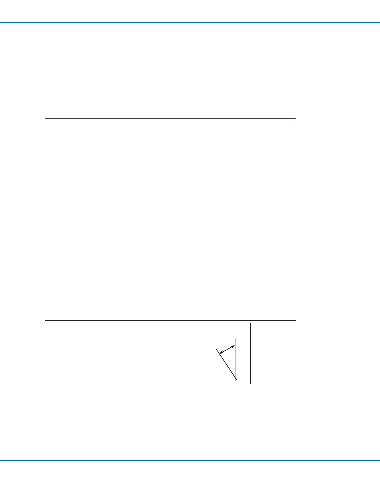
Torque: 5 N•m (3.7 ft-lb) maximum
• Optional: Install a tube connector (for non-syringe barrel
installations).
Continued on next page
~15°
15nordsonefd.com [email protected] 800-556-3484 Sales and service of Nordson EFD dispensing systems are available worldwide.
Page 16

Liquidyn P-Jet CT Jet Valve
Assemble the Valve (Initial Assembly) (continued)
5.
(Syringe barrel installations only) Mount the syringe barrel
holder.
6.
(Syringe barrel installations only) Install the syringe barrel
and syringe barrel adapter.
Change the Fluid Body or Tappet (Optional)
Follow this procedure to use an optional uid body or tappet. You will need the following items:
• Replacement uid body
• Replacement tappet
• Barrier grease
• Wooden pick
1.
• Unscrew and remove the four screws that secure the uid
body.
• Carefully remove the uid body without damaging the
tappet.
2.
Loosen the tappet nut with a wrench (6 mm to loosen the
tappet nut; 3.5 mm to hold the tappet rod steady).
Continued on next page
16 nordsonefd.com [email protected] 800-556-3484 Sales and service of Nordson EFD dispensing systems are available worldwide.
Page 17

Change the Fluid Body or Tappet (Optional) (continued)
3.
• Press in the tappet with controlled pressure until the
clamping sleeve between the tappet and nut loosens. A
piece of wood or hard rubber is suitable to press against.
• Remove the tappet.
4.
• Insert the replacement tappet until the tappet stops.
• Tighten the tappet nut using the same technique
described in step 2.
Torque: 0.1 N•m (0.7 ft-lb) maximum
5.
Using a wooden pick, apply a small amount of barrier grease
(Barriereta L55/2) at the base of the replacement tappet and
distribute this around the annulus.
NOTE: When dispensing instant adhesive (cyanoacrylates),
Nordson EFD recommends petroleum jelly for use as the
barrier grease. Contact Nordson EFD for assistance in
dispensing cyanoacrylates.
Liquidyn P-Jet CT Jet Valve
6.
• Install a new O-ring (standard material: NBR) on the tappet
and press the O-ring down into the greased annulus.
• Distribute the grease evenly so that the entire sealing
surface of the O-ring is covered.
• Install the second (grease-free) O-ring on the tappet on
top of the initial O-ring.
7.
Mount the initial or replacement uid body precisely over the
tappet without tilting it. Tighten the screws crosswise.
Torque: 0.8 N•m (5.9 ft-lb) maximum
17nordsonefd.com [email protected] 800-556-3484 Sales and service of Nordson EFD dispensing systems are available worldwide.
Page 18

Liquidyn P-Jet CT Jet Valve
Install a Nozzle Heater (Optional)
Install the optional nozzle heater as shown in the illustration below. A nozzle heater controls the temperature of
the material in the nozzle. The nozzle is secured minimally by the nozzle heater with an elastomer (heater O-ring)
between it and the valve. The nozzle is fully secured by the retaining nut.
You will need the following items:
• Nozzle
• Nozzle heater
• Nozzle heater O-ring (NBR or EPDM)
• Retaining nut
• Heater key
• Heater cable
Refer to “Replacement Parts” on page33 for component part numbers.
NOTES:
• The nozzle retaining nut predominantly secures and seals the nozzle in place. The heater remains in contact with
the retaining nut through pressure supplied by a heater O-ring, which creates a partial space between the heater
and the uid body. This ensures thermal contact and allows the heater to rotate slightly even when the retaining
nut is fully tightened.
• The image below is based on a Liquidyn P-Dot valve with a standard nozzle heater. The mounting process is the
same for all valves.
Nozzle
Nozzle heater O-ring
Nozzle heater
Nozzle retaining nut
Heater key
Torque for a steel nozzle: 1.2 N•m (10.6 in.-lb)
Torque for a plastic nozzle: 0.5 N•m (4.4 in.-lb)
NOTES:
• The electrical connection for the
heater is supplied through the
provided heater cable.
• To attach or release the heater cable,
loosen or tighten the knurled nut by
hand. Be sure to connect the heater
cable plug in the correct orientation.
18 nordsonefd.com [email protected] 800-556-3484 Sales and service of Nordson EFD dispensing systems are available worldwide.
Page 19
Mount the Valve
Mount the valve using either of the following options.
Standard Mounting
Secure the valve using two M3 x 25 hex screws (customer-supplied).
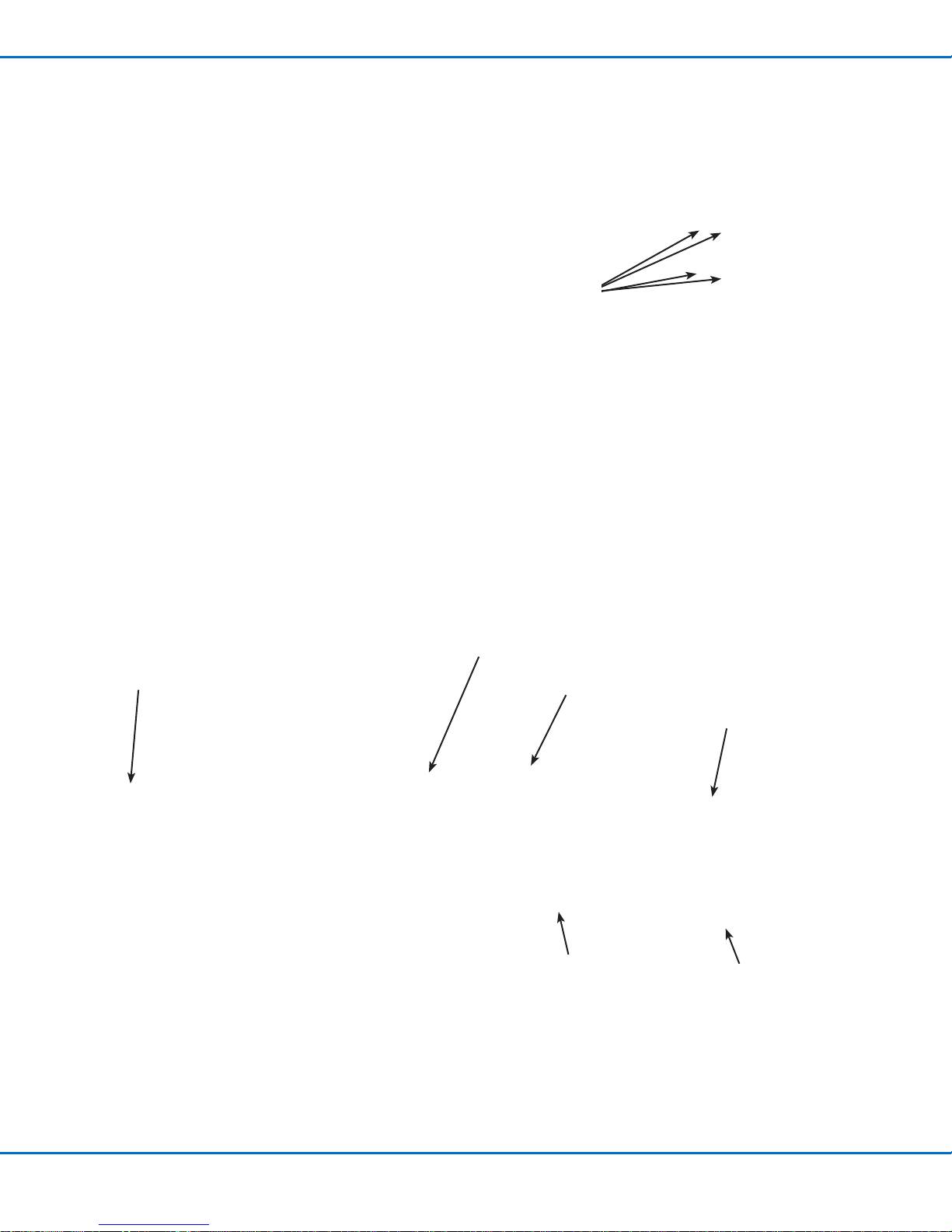
Four mounting holes are available to allow for adjustment.
M3 mounting
hole locations
Quick-Mounting
An optional quick-mounting bracket is available for faster valve removal
and installation. Once the valve is installed using the quick-mounting
components, it can be easily removed or installed using the quickrelease fastener. Refer to “Replacement Parts” on page33 for the
quick-mounting kit part number.
You will need the following items:
• Vibration decoupler
• Quick-release fastener
• 2 M4 hex screws (minimum length: 10 mm)
• Hex wrench, size 2.5
• Hex wrench, size 3.0
Liquidyn P-Jet CT Jet Valve
M3 x 30
mounting screws
Example of the quick-release mounting option
Vibration decoupler
Hook (hooks into the
quick-release fastener)
M4 x 30 mounting
screws (for mounting
onto a socket; not
included)
Quick-release fastener
Lever (secures the hook)
19nordsonefd.com [email protected] 800-556-3484 Sales and service of Nordson EFD dispensing systems are available worldwide.
Page 20

Liquidyn P-Jet CT Jet Valve
Connect Cables
Connect the M8 valve cable and other communication cables as applicable for your system to control the operation
of the valve. The diagram below shows some typical system control setups.
NOTE: The valve is triggered by a square-wave signal (24 VDC). The length of the pulse from the control signal
denes the opening time of the valve and can be set from 2 ms to innity. Most PLC systems make use of high
performance transistor outputs which are suitable to control the valve directly. The valve is electrically connected to
the control system via the supplied M8 valve cable.
V10
V200
PLC
PLC
P-Jet CT
P-Jet CT
V10
V200
V10
PLC
T10
PLC
Key:
T10 = Liquidyn T10 or T20 heater controller
V10 = Liquidyn V10, V10M, V10D, or M10D controller
V200 = Liquidyn V200 controller
PLC = Higher-level controller
P-Jet CT
P-Jet CT
P-Jet CT
P-Jet CT
20 nordsonefd.com [email protected] 800-556-3484 Sales and service of Nordson EFD dispensing systems are available worldwide.
Page 21

Liquidyn P-Jet CT Jet Valve
Connect the Air Supply
To achieve consistent dispensing results, the process parameters must be kept constant. The valve has two air
pressure connections (operating pressure and uid pressure) which must be continuously supplied with air pressure.
The level of pressure depends on the respective process. Each valve must be separately connected to a continuous
air supply adjustable through a precision pressure regulator. To keep the operating pressure stable and constant,
use a pneumatic accumulator (at least 0.4 liter volume).
CAUTION
Ensure that the pressure limit values for the syringe barrel and air pressure tubing are not exceeded.
1. For the operating pressure, connect 6 mm OD tubing to the plug-in connector on the side of the valve.
2. For the uid pressure, connect 4 mm or 6 mm tubing to the syringe barrel adapter (syringe barrel installations
only).
NOTE: Nordson EFD recommends installing a precision pressure regulator with a maximum control tolerance of
0.2%.
Air input
(uid pressure; syringe
barrel installation shown)
Air input (operating
pressure)
21nordsonefd.com [email protected] 800-556-3484 Sales and service of Nordson EFD dispensing systems are available worldwide.
Page 22

Liquidyn P-Jet CT Jet Valve
Installation Example
Item Description
Pneumatic connections
Fluid connection
Electrical connections
Optional
• Compressed air tube, 6 mm OD
• Dry, ltered air pressure, oil-free
• Filter grade: 40 µm
• Regulated by a precision pressure regulator
• Operating pressure limit: 3–8 bar (44–116 psi)
• Using a syringe barrel supply: Syringe barrel accessories with compressed 4 mm
air tubing)
• Using a tube supply: Tube connector with uid tubing
• Fluid pressure limit: 100 bar (1450 psi)
• Supplied M8 valve cable from the valve to a Liquidyn valve controller or a higherlevel controller, such as a PLC
• Power supply: 24 VDC
• Power consumption: 0.5 Amp (peak 5.0 Amp)
• Nozzle heater (controlled by a temperature control unit)
• Process equipment (such as a laser light barrier for dot recognition or a cleaning
station for nozzles)
Tube connection
Syringe barrel
connection
Valve cable
Connection depends on material supply method
Fluid tubing
Higher-level controller
(e.g., PLC)
Fluid
reservoir
Fluid pressure
4 mm air supply tubing
Precision
pressure
regulator
Air pressure source
Precision
pressure
regulator
Operating pressure
6 mm air supply tubing
Liquidyn P-Jet CT valve connection diagram
22 nordsonefd.com [email protected] 800-556-3484 Sales and service of Nordson EFD dispensing systems are available worldwide.
Pressure
accumulator
(at least 0.4 liter)
Page 23

Liquidyn P-Jet CT Jet Valve
Initial Startup
This section provides recommendations for system startup and operation. System startup for the valve depends
on the control unit. If you are using a Nordson EFD Liquidyn valve controller, obtain the controller manual. If you are
using higher-level controller, the control is set up by the customer.
CAUTION
Before switching on the system, ensure that all electrical and pneumatic connections are connected correctly and
fully functioning.
1. Check electrical and pneumatic connections.
2. Switch on the control unit.
3. Turn on the air supplies.
4. Use the following actions to set up and test the valve operation using the control system manual or the
customer-supplied control system and documentation. Refer to “Parameter Settings” on page24 for
information and recommendations on system setup.
a. Trigger the valve until the material to be dispensed leaves the nozzle opening. Place a collecting container or
a paper sheet underneath the valve.
b. Clean the nozzle tip with a lint-free cloth.
c. Set the distance between the nozzle and the target (such as a sample product).
d. Initiate several dispense cycles to test the valve operation.
e. Evaluate the dispensing results and make adjustments until the desired dispensing performance is achieved.
Refer to “Parameter Settings” on page24 and to “Recommended Setup Adjustments” on page25 for
detailed information on system setup and adjustment.
5. To ensure optimal valve performance, maintain the system as described under “Service” on page28.
23nordsonefd.com [email protected] 800-556-3484 Sales and service of Nordson EFD dispensing systems are available worldwide.
Page 24

Liquidyn P-Jet CT Jet Valve
Parameter Settings
The following table provides recommended settings for initial startup and testing of the valve operation. Detailed
information on each parameter is shown after the table.
Parameter Description Recommendation
Pulse Time The electrical trigger pulse of the valve, starting at 2 ms. 2 ms starting value
Frequency The number of tappet movements per second. 5Hz starting value
Fluid pressure The ow rate of the material supply; should be set to produce a
consistent volume.
Operating pressure The setting of the tappet force screw; can be adjusted to ne-tune
the dispensing result.
Stroke adjustment The setting of the stroke adjustment knob, which changes the
vertical movement of the tappet.
Pulse Time
The Pulse Time corresponds to the electrical trigger pulse, or opening time, of the valve, which is the primary control
of deposit size. The following conditions apply to Pulse Time:
• The pneumatically actuated dispensing nozzle remains
open as long as it is triggered.
1.5 bar (22 psi)
starting value
5 bar (73 psi) starting
value
Do not adjust
• The dispensing volume is affected by the adjustment of
the triggering pulse.
• The minimum Pulse Time is 2 ms. The valve cannot
operate correctly at Pulse Times below 2ms.
Frequency
Frequency is the number of tappet movements per second. A dispensing cycle consists of the Pulse Time and the
pause time.
Physical Quantity Formula Unit
Frequency (f) f = 1 / T 1Hz (hertz) = 1 / s
Dispensing cycle T = 1 / f 1 s (second) = 1 / Hz
1 ms = 0.001 s (second)
Higher-level controllers may not allow you to enter the exact frequency. If such cases, frequency is set using the
length of the pulse and the pause time.
EXAMPLE:
• To achieve 50Hz with a 2 ms Pulse Time, set the pause time to 18 ms.
• To achieve 50Hz with a 10 ms Pulse Time, set the pause time to 10 ms.
Dispensing cycle
Pulse time Pause time
24 nordsonefd.com [email protected] 800-556-3484 Sales and service of Nordson EFD dispensing systems are available worldwide.
Page 25
Liquidyn P-Jet CT Jet Valve
Parameter Settings (continued)
Fluid Pressure
The uid pressure must be properly set to ensure that material is supplied at a consistent volume. Consider the
following when setting the uid pressure:
• The uid pressure must stay within the tubing pressure specications.
• Fluid supply tubing must be resistant to chemicals.
• The uid pressure must be high enough for the material to exit the nozzle opening.
• The required uid pressure will vary depending on the material, its viscosity, and the ambient temperature.
• Decreasing the uid pressure too much may, in extreme cases, prevent proper deposit separation from the
nozzle.
• Prevent pressure uctuations. Note that pressure loss due to friction occurs as material ows through the
material delivery components.
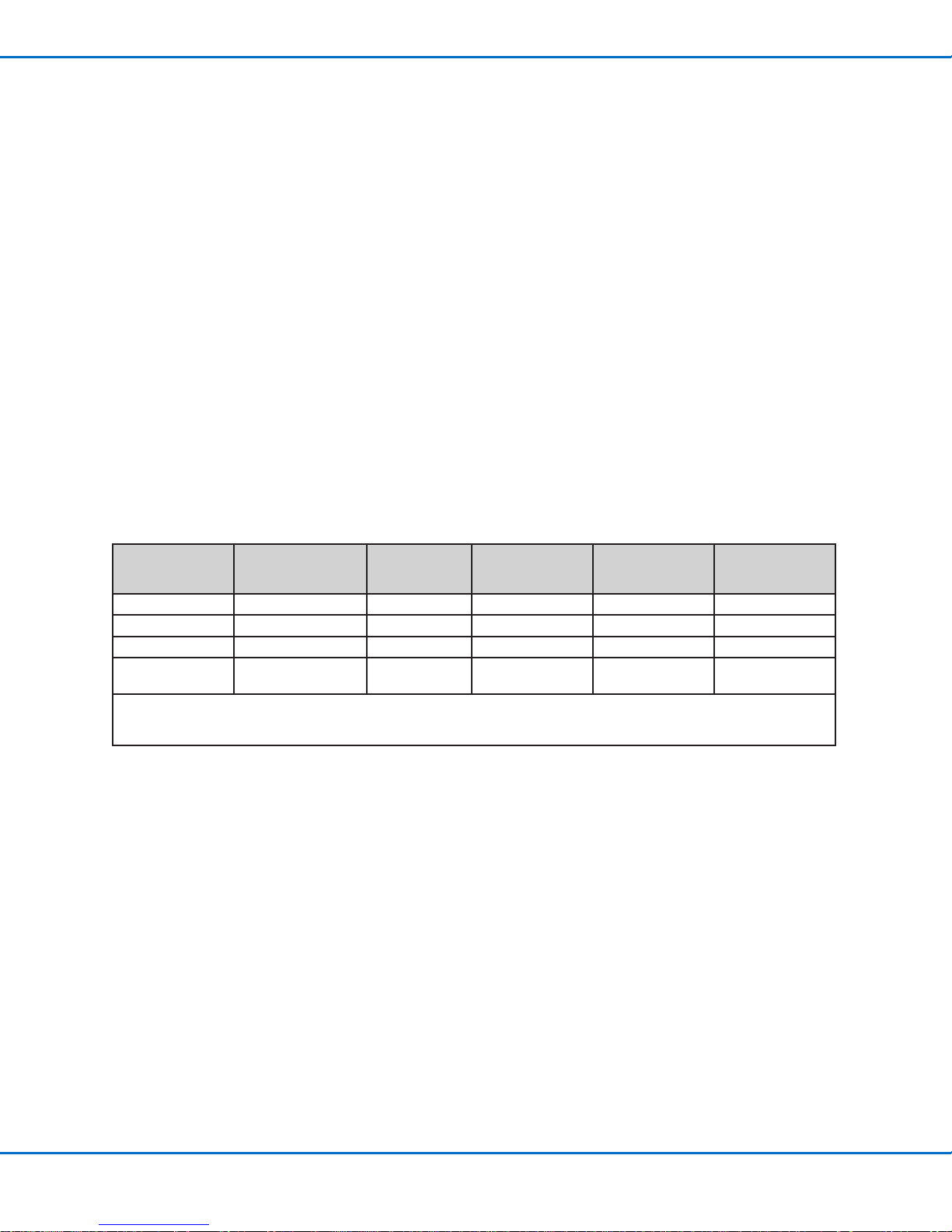
Recommended Setup Adjustments
The following table provides recommended adjustments to help you quickly nd optimum system settings
for your application. Because of the diversity in materials that can be dispensed, the effectiveness of these
recommendations can vary, but they serve to share our experience with you.
Goal Operating Pressure
Smaller dots Not applicable Down Down Down Down
Bigger dots Not applicable Up Up Up Up
Prevent satellites Down Up Down Down Up
Prevent residue at
the nozzle
Key:
Down = lower operating pressure or temperature / tighten screw / smaller diameter
Up = greater operating pressure or temperature / loosen screw / larger diameter
Up Down Down Up Not applicable
Tappet
Force Screw
Adjustment
Fluid Pressure
Heater
(Temperature)
Nozzle Orifice
Diameter
25nordsonefd.com [email protected] 800-556-3484 Sales and service of Nordson EFD dispensing systems are available worldwide.
Page 26

Liquidyn P-Jet CT Jet Valve
Tappet Adjustment
The valve is equipped with two mechanisms for tappet
adjustment:
• Force screw (non-slip knurled screw) — sets the
dynamic of the tappet movement.
• Stroke adjustment knob (fine diamond knurl screw) —
sets the tappet stroke.
The factory settings for both mechanisms are appropriate for
most applications. However, depending on the dispensing
task and on the material, each can be adjusted to ne-tune the
dispensing result.
Adjusting the Force Screw
Adjust the raster element (see NOTE below) and then turn
the force screw clockwise (as seen from an aerial view) to
change the dynamic of the tappet movement. In most cases,
simultaneously increasing the operating pressure is helpful.
Refer to the table below for recommended force screw settings
based on the viscosity of the material.
NOTE: Use the spring-loaded raster element as follows:
Stroke adjustment
knob
Force screw
Force screw
Spring-loaded
raster element
• Completely loosen the element to turn the force screw.
• Half-tighten the element to hear a clicking sound when you turn the force screw.
• Completely tighten the element to secure the force screw.
Dispensing
Material
Viscosity Process
Low Dots / lines 25 3.0–3.5 bar (44–51 psi) Plastic needle nozzle with a steel tip
Low Small dots 30 4.0–4.5 bar (58–65 psi) Plastic needle nozzle with a tapered steel tip
Medium Dots 30 4.5–5.0 bar (65–73 psi) Steel needle nozzle
High Dots 35–45 Up to 8.0 bar (116 psi) Steel at nozzle
Number of
Screw Clicks
(starting from
the upper stop) Operating Pressure Nozzle Type
To return the force screw to the factory setting:
1. Completely loosen the raster element.
2. Turn the force screw counterclockwise until it stops.
3. Turn the force screw clockwise for 25 clicks (15 clicks = one full turn).
4. Completely tighten the raster element to secure the force screw.
26 nordsonefd.com [email protected] 800-556-3484 Sales and service of Nordson EFD dispensing systems are available worldwide.
Page 27

Adjusting the Stroke
CAUTION
Do not keep turning the stroke adjustment knob after you feel the torque elevate.
Doing so can damage the valve.
1. Use a hex wrench to loosen the locking set screw.
Liquidyn P-Jet CT Jet Valve
2. Turn the stroke adjustment knob clockwise (as seen from an
aerial view) to reduce the stroke.
3. Tighten the locking set screw to secure the knob.
Torque: 0.3 N•m (2.7 in.-lb) maximum
Stroke adjustment
NOTE: For very ne adjustment of the tappet stroke, loosen the
locking screw 2 turns, turn the stroke adjustment knob + 90° / - 90°
from its factory position, and observe the deposit cut-off or shape.
When the desired dispensing result is achieved, tighten the locking
screw. Note that in this situation the maintenance intervals described
under “Service” on page28 will need to be adapted depending on
the dispensed material and on the stroke.
To return the stroke adjustment knob to the factory setting:
1. Loosen the locking set screw.
2. Turn the stroke adjustment knob clockwise (as seen from an aerial view) until
the stroke stop lies at against the valve tappet. This can be felt when the
torque elevates.
3. Turn the knob 270° counterclockwise.
4. Tighten the locking set screw to prevent accidental turning of the knob.
Torque: 0.3 N•m (2.7 in.-lb) maximum
Locking set screw
knob
27nordsonefd.com [email protected] 800-556-3484 Sales and service of Nordson EFD dispensing systems are available worldwide.
Page 28

Liquidyn P-Jet CT Jet Valve
Service
Regularly perform maintenance on your micro-dispensing valve. Regular maintenance will save you cost-intensive
repairs and is a requirement for long valve lifespan. Nordson EFD valves are designed to be maintained easily. All the
material-carrying parts can be removed, cleaned, and maintained by the customer.
NOTE: Customers should service only the material-carrying components. For any service not related to the materialcarrying components, contact your Nordson EFD support representative.
Recommended Maintenance Schedule
Cleaning and maintenance intervals vary based your operating conditions (dispensing frequency, frequency of use,
dispensing material, etc.). The following table provides recommendations only.
Variable Perform Weekly Valve Cleaning
Dispensing frequency Less than 20Hz Greater than 20Hz
Dispensing material
NOTE: The sealing effectiveness of the tappet O-rings can be compromised if the replacement intervals are too long
(causing worn or damaged O-rings). Worn or damaged O-rings can cause dispensing material to enter the drive
system, thus compromising valve operation. When this occurs, the valve must be sent back to Nordson EFD for
rebuilding.
• Oil
• Grease
• UV glue
Perform Daily Valve Cleaning (or at the end
of the pot life)
• Dispersions
• Reactive adhesives
• Epoxies
Valve Cleaning
You will need the following items:
• Protective clothing
• Hex wrench, size 10
• Hex wrench, size 2
• Toothpick
• Cleaning material
• Container
• Compressed air
• Lint-free cloth
• Optional: Ultrasonic bath
• Optional: Microscope
WARNING
• Before any component change or service activity, relieve air pressure from the uid reservoirs and switch off
heater control (if applicable).
• Disconnect the system from the power supply before beginning work on electrical or electronic system
components or opening the switchgear cabinet.
• Disconnect the mains power plug to isolate the system from the power supply. Check for safe isolation from the
power supply using suitable measuring instruments. Only perform maintenance work on a system that is safely
isolated from the power supply.
• Wear appropriate personal protective equipment, including, but not limited to, gloves, safety goggles, and
breathing protection.
• Switch off the compressed air supply before disconnecting the system from the pneumatic connections.
• Read and understand the SDS for the dispensing material and the risk of the associated health hazards so that
suitable safety measures can be taken for the correct handling of the dispensing material.
28 nordsonefd.com [email protected] 800-556-3484 Sales and service of Nordson EFD dispensing systems are available worldwide.
Page 29

Liquidyn P-Jet CT Jet Valve
Service (continued)
Shut Down the System
1. Shut off the air supply.
2. Switch off the power of every control unit, then switch off power to the valve.
3. Disconnect all tubing and cables.
4. Disconnect the material supply.
5. Continue with the procedures in this section to disassemble and clean the valve.
Disassemble the Valve
CAUTION
Do not open the color-sealed screws. Unauthorized modications and the breaking of the sealed screws void the
warranty and guarantee.
1.
(Syringe barrel installations only) Remove the syringe
barrel from the valve.
2.
• (Syringe barrel installations only) Disconnect the luer
lock adapter from the uid body.
• Optional: Remove the tube connector.
3.
• Unscrew the nozzle retaining nut.
• Optional: If you are using a heater, use the heater key
to remove the nozzle retaining nut.
4.
Remove the nozzle from the uid body.
Continued on next page
29nordsonefd.com [email protected] 800-556-3484 Sales and service of Nordson EFD dispensing systems are available worldwide.
Page 30

Liquidyn P-Jet CT Jet Valve
Service (continued)
Disassemble the Valve (continued)
5.
• Unscrew and remove the four screws that secure the
uid body.
• Carefully remove the uid body without damaging the
tappet.
6.
Use a toothpick to remove the O-ring from the uid body.
7.
• Remove the second O-ring from the tappet.
• Clean the tappet and annulus with lint-free paper.
Clean the Valve Components
CAUTION
Never use solvents or cleaning agents that contain halogenated hydrocarbons (such as trichloroethane, methyl
chloride, or dichloromethane). Halogenated hydrocarbons can dissociate, causing an explosion upon contact with
aluminum and galvanized surfaces. Before using a solvent or cleaning agent, check its ingredients.
1.
• Submerge all the components in a container lled with
cleaning uid.
• After 3–5 minutes, remove the components from the
container and clean them with a lint-free cloth.
CAUTION
Do not damage the holes on the sealing faces of the
material carrying components.
• Optional: Use an ultrasonic bath to clean the
components.
2.
Use the pipe cleaners from the cleaning kit to clean the
disassembled components (luer lock adapter, nozzle
retaining nut, nozzle, uid body, and the tappet if
needed).
Continued on next page
30 nordsonefd.com [email protected] 800-556-3484 Sales and service of Nordson EFD dispensing systems are available worldwide.
Page 31

Service (continued)
Clean the Valve Components (continued)
3.
• Use compressed air to clear any remaining cleaning
uid from the parts.
CAUTION
Do not damage the holes on the sealing faces of the
material carrying components.
• Examine the cleaned components for any remaining
residue (especially the nozzle, which should be
examined under a microscope).
• If the parts are still contaminated, repeat the cleaning
process.
Assemble the Valve (After Cleaning)
Follow this procedure to assemble a valve after cleaning it. You will need the following items:
• Hex wrench, size 10
• Hex wrench, size 2.5
• Nozzle
• Nozzle retaining nut
• O-rings and barrier grease
• Wooden pick
• Optional: Heater key (if installing a nozzle heater)
NOTE: The steps provided in this manual are based on a valve with a syringe barrel.
Liquidyn P-Jet CT Jet Valve
1.
Using a wooden pick, apply a small amount of barrier grease
(Barriereta L55/2) at the base of the tappet and distribute
this around the annulus.
NOTE: When dispensing instant adhesive (cyanoacrylates),
Nordson EFD recommends petroleum jelly for use as the
barrier grease. Contact Nordson EFD for assistance in
dispensing cyanoacrylates.
2.
• Install a new O-ring (standard material: NBR) on the tappet
and press the O-ring down into the greased annulus.
• Distribute the grease evenly so that the entire sealing
surface of the O-ring is covered.
• Install the second new (grease-free) O-ring on the tappet
on top of the initial O-ring.
3.
• Mount the uid body precisely over the tappet without
tilting it. Tighten the screws crosswise.
Torque: 0.8 N•m (5.9 ft-lb) maximum
• Optional: To use a different tappet, go to “Change the
Fluid Body or Tappet (Optional)” on page16. Return
here to continue.
Continued on next page
31nordsonefd.com [email protected] 800-556-3484 Sales and service of Nordson EFD dispensing systems are available worldwide.
Page 32

Liquidyn P-Jet CT Jet Valve
Service (continued)
Assemble the Valve (After Cleaning) (continued)
4.
Install the nozzle.
5.
Secure the nozzle with the retaining nut.
NOTE: The nozzle is only minimally secured by a nozzle
heater. The nozzle is fully secured by the retaining nut.
6.
(Syringe barrel installations only)
• By hand, thread the luer lock adapter loosely onto the
uid body.
• Position the luer lock adapter at a 15-degree angle to its
end position and then tighten the nut with a wrench so
that the adapter is level with the straight axis of the valve.
Torque: 5 N•m (3.7 ft-lb) maximum
• Optional: Install the tube connector.
7.
(Syringe barrel installations only) Mount the syringe barrel
holder.
8.
• (Syringe barrel installations only) Install the syringe barrel
and syringe barrel adapter.
• Mount the valve and restore the system to normal
operation.
~15°
32 nordsonefd.com [email protected] 800-556-3484 Sales and service of Nordson EFD dispensing systems are available worldwide.
Page 33
Liquidyn P-Jet CT Jet Valve
Replacement Parts
Valve Components
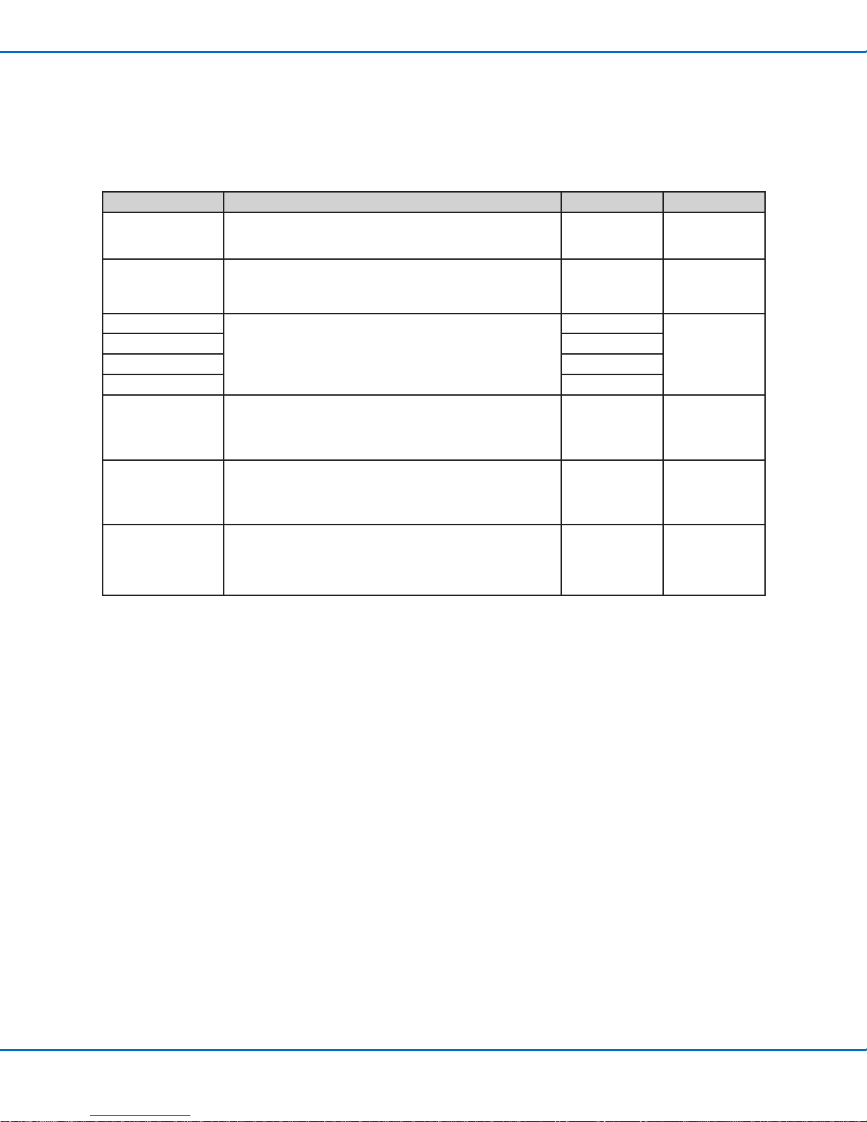
Refer to “Operating Features” on page13 for the location of the these components in the valve.
Part # Description Material Item
7825024* Tappet, P-Jet CT, 40L x 2.0D mm Steel
7825028* Tappet, P-Jet CT, 40L x 2.0D mm Ceramic
7825189
7825188 EPDM
7825230 Perlast
7825190 Viton
7825037* Steel uid body
7825038* Plastic uid body PEEK**
7825182 2.5 m (8.2 ft) M8 valve cable n/a
*Other selections are available. Contact your Nordson EFD application specialist for assistance.
**Polyetheretherketone
O-rings (between the tappet and uid body)
NBR
303 stainless
steel
33nordsonefd.com [email protected] 800-556-3484 Sales and service of Nordson EFD dispensing systems are available worldwide.
Page 34

Liquidyn P-Jet CT Jet Valve
Replacement Parts (continued)
Nozzles and Nozzle Retaining Nuts
Nozzle
Type
Flat 7825063*
Needle 7825075*
Needle
*Many nozzle types and sizes are available. Contact your Nordson EFD application specialist for assistance.
The retaining nut secures the nozzle to the valve. The choice of retaining nut depends on the type of nozzle and
whether or not a nozzle heater is installed. Contact your Nordson EFD application specialist for assistance.
Nozzle
Type
Without
heater
Part # Description Material Item
Steel at nozzle, 150 μm
NOTE: Plastic at nozzles are also available.
Steel needle nozzle, 150 μm
NOTE: Plastic needle nozzles are also
available.
7825094* Plastic needle nozzle with steel tip, 150 μm
7825100* Plastic needle nozzle with PTFE tip, 200 μm PEEK / PTFE
Part # Description Material Compatibility Item
7825042*
7825044*
Hexagon retaining
nut
Knurled retaining
nut
Stainless steel
Stainless steel
For all at nozzles and steelneedle nozzles
For plastic-needle nozzles with a
steel or PTFE-coated tip
303 stainless steel
303 stainless steel
PEEK /
303 stainless steel
7825051*
With heater
7825047*
*Other selections are available. Contact your Nordson EFD application specialist for assistance.
Stainless-steel
retaining nut
Stainless-steel
retaining nut
Stainless steel
Stainless steel
For the standard nozzle heater
(compatible with all nozzle types)
For the small nozzle heater
(compatible with all nozzle types)
34 nordsonefd.com [email protected] 800-556-3484 Sales and service of Nordson EFD dispensing systems are available worldwide.
Page 35

Liquidyn P-Jet CT Jet Valve
Replacement Parts (continued)
Syringe Barrels and Accessories
Many syringe barrel sizes and accessories are available. Contact your Nordson EFD application specialist for
assistance.
5, 6
4
2, 3
1
Item Description Configuration Options
• Luer lock adapter for 3cc to 50cc syringe barrels • Steel
1
• PEEK
• 10cc syringe barrel
2
• 30cc syringe barrel
• 10 ccm stopper
3
• 30 ccm stopper
• 10 ccm syringe barrel holder
4
• 30 ccm syringe barrel holder
• 10 ccm syringe barrel adapter for 4 mm OD tube connection
5
• 30 ccm syringe barrel adapter for 4 mm OD tube connection
• 10 ccm O-ring (NBR) for syringe barrel adapter
6
• 30 ccm O-ring (NBR) for syringe barrel adapter
• Normal
• Light-proof
• UV-blocker
• Normal
• UV-blocker
• Steel
• PEEK
Typical Luer Lock Fittings
Part # Description Material Item
7825120* Steel luer lock adapter for syringe barrels Stainless steel
7825121* Plastic luer lock adapter for syringe barrels PEEK
*Other selections are available. Contact your Nordson EFD application specialist for assistance.
35nordsonefd.com [email protected] 800-556-3484 Sales and service of Nordson EFD dispensing systems are available worldwide.
Page 36

Liquidyn P-Jet CT Jet Valve
Replacement Parts (continued)
Material Supply Tubing Components
The following material supply tubing and connectors are available from Nordson EFD. Additional selections may be
available. Contact your Nordson EFD application specialist for assistance.
Steel Tubing Connectors
Part # Description Material Item
7825137 4 mm OD tubing connector
7825138 6 mm OD tubing connector
7825139 8 mm OD tubing connector
Plastic Tubing Connectors
NOTE: A plastic luer lock adapter is required to install a male or female luer lock tube connector.
Part # Description Material Item
7825136 3.2 mm OD tubing connector PEEK
7825134 Male luer lock tube adapter 6 mm OD tubing PTFE
7825135 Female luer lock tube adapter 4 mm OD tubing Polypropylene (PP)
Stainless steel / aluminum
Tubing
Part # Description Material
7825278 3.2 mm (1/8") PTFE tubing PTFE
7825280 4 mm OD / 2.6 mm ID PTFE tubing PTFE
7825281 6 mm OD / 4 mm ID PTFE tubing PTFE
7825282 4 mm OD compressed air tubing Polyurethane (PU)
7825283 6 mm OD compressed air tubing Polyurethane (PU)
36 nordsonefd.com [email protected] 800-556-3484 Sales and service of Nordson EFD dispensing systems are available worldwide.
Page 37
Liquidyn P-Jet CT Jet Valve
Replacement Parts (continued)
Accessories
Quick-Release Valve Mounting Components
When a valve is installed using these components, it can be quickly and easily removed and reinstalled. Refer to
“Quick-Mounting” on page19 for installation instructions.
Part # Description Item
7825018 Vibration decoupler
7825020 Quick-release fastener
— Two (2) M4 hex screws (minimum length: 10 mm) Customer supplied
Precision Pressure Regulator
Nordson EFD recommends a dry, oil-free, ltered air supply (40 µm lter grade).
Part # Description
7825268 Precision pressure regulator
37nordsonefd.com [email protected] 800-556-3484 Sales and service of Nordson EFD dispensing systems are available worldwide.
Page 38

Liquidyn P-Jet CT Jet Valve
Replacement Parts (continued)
Nozzle Heaters
Many materials can easily be dispensed without preheating. However, it is often advisable to preheat highly viscous
materials just before application to lower the viscosity. Doing so can prevent variations in viscosity. The use of
a nozzle heater guarantees a constant temperature of the material to be dispensed at the nozzle. Contact your
Nordson EFD application specialist for assistance.
A nozzle heater can be installed on the valve in place of the retaining nut. The heater can be controlled using a
separate temperature controller (such as the Liquidyn T10) or by the Liquidyn V200 controller.
NOTES:
• Nozzle heater O-rings are available in NBR or EPDM. Refer to “Nozzle Heater O-Rings” below for part numbers.
• A special heater key is required for installation. Refer to “Heater Key” below for the part number.
Heater Type Heating Capability Nozzle Heater
Standard Up to 90° C (194° F)
Small (a small heater has a
low-prole height and is less
thick overall)
Up to 90° C (194° F)
Nozzle Heater O-Rings
Two types of nozzle heater O-ring are available.
Part # Description Material
7825234 NBR nozzle heater O-ring NBR
7825235 EPDM nozzle heater O-ring EPDM
Heater Key
The heater key is required to install the heater retaining nuts.
Part # Description Item
7825209 Heater key
38 nordsonefd.com [email protected] 800-556-3484 Sales and service of Nordson EFD dispensing systems are available worldwide.
Page 39

Replacement Parts (continued)
Tools and Supplies
Item Part # Description
1.5 g: 7825262
5.0 g: 7825263
0.12 mm: 7825205
0.16 mm: 7825206
0.2 mm: 7825207
0.25 mm: 7825208
7825210 Nozzle pinch tools
NBR: 7825192
EPDM: 7825191
Perlast: 7825194
Viton: 7825196
EPDM: 7825198
Viton: 7825197
Barrier grease for O-rings
Nozzle cleaning probes
Standard cleaning kit (order based on O-ring type)
Expanded cleaning kit (order based on O-ring type)Perlast: 7825195
Liquidyn P-Jet CT Jet Valve
39nordsonefd.com [email protected] 800-556-3484 Sales and service of Nordson EFD dispensing systems are available worldwide.
Page 40

Liquidyn P-Jet CT Jet Valve
52 mm (2")
ca. 128 mm (5")
Technical Data
Dimensions
11.5 mm
(0.5")
15 mm
(0.6")
13 mm
3.2
(1.0")
23 mm
17.5 mm (0.7")
M8 x 1
(0.5")
SW10
(0.4")
10.5 mm
M8 Valve Cable Pin Positions
Pin Color Function
1 Brown None
2 Black Valve (+)
3 Blue Valve (-)
(0.5")
13.5 mm
15 mm
(0.6")
45.5 mm (1.8")
20 mm
(0.8")
40 nordsonefd.com [email protected] 800-556-3484 Sales and service of Nordson EFD dispensing systems are available worldwide.
Page 41

Liquidyn P-Jet CT Jet Valve
Appendix A, About Non-Contact Dispensing
The way a micro-dispensing valve system works for the non-contact dispensing of micro-deposits of uid is
comparable to the way an ink-jet system works. In both systems, a jetted deposit with a spherical head and a thin
thread (shaped much like a tadpole) is formed. The dimensions vary depending on the material being dispensed, the
process, and the valve settings.
As the deposit is squeezed (or jetted) out of the nozzle opening, the thin thread constricts because of the absence
of further uid supply, the surface tension, and also the continual movement of the deposit, until the deposit nally
separates from the nozzle opening. The thread extending from the deposit’s spherical head is either absorbed by
the head or separated into at least one more (sometimes many more) smaller head. This depends on the rheological
properties of the uid. At low airows or in asymmetrical drop-off conditions, a smaller head can land on the
substrate next to the main head, creating satellite drops. The thin thread formed at the nozzle output retracts back
into the nozzle due to the surface tension and remains at the nozzle output. This residue at the nozzle output can
have a negative inuence on the dispensing properties of the valve.
The formation of satellite drops and / or nozzle contamination can be reduced or eliminated by using the correct
dispensing settings.
Low Viscosity Materials
Try the following to reduce or eliminate the formation of satellite drops: Reduce the pressure supplied to the material
by reducing both the uid pressure and the operating pressure and also by loosening the force screw. Refer to
“Adjusting the Force Screw” on page26.
NOTE: With low viscosity materials, nozzle contamination is usually a minor issue because the subsequent drop
removes the residue at the nozzle output.
High Viscosity Materials
With high viscosity materials, the thin thread that retracts back into the nozzle and the resulting nozzle
contamination can negatively affect the dispensing process. Try the following to reduce or eliminate nozzle
contamination:
• Increase the amount of supplied force. The amount of force depends on the operating pressure and the
pretension of the valve tappet. Increasing the amount of force can have a positive effect on the drop-off
properties of the deposit and thus improve process reliability. Refer to “Adjusting the Force Screw” on
page26.
• Warm the material being dispensed to reduce the viscosity. This is particularly effective for highly viscous
materials. In most cases, the dispensing process reliability of highly viscous materials improves with decreased
viscosity. Material warming can be accomplished by installing a nozzle heater. Refer to “Install a Nozzle Heater
(Optional)” on page18.
NOTE: In general, viscosity halves per 10 Kelvin temperature unit increase. Exceptions are silicone oils and greases,
although elevating the temperature of these materials can lead to improvement.
Deposit Size
The dispensed volume of a deposit depends on the following parameters:
• Cross section of the valve
• Operating pressure
• Fluid pressure
• Position of the stroke adjustment screw or the force screw.
The smallest possible deposit size is subject to physical limitations. The smaller the deposit, the higher the surface
tension in relation to its mass. Thus, the amount of required energy needed for the launch of a deposit raises
signicantly in relation to its mass. At a certain point, it is physically impossible to transfer the required energy to the
dispensed material any longer, particularly in the dispensing of highly viscous materials.
41nordsonefd.com [email protected] 800-556-3484 Sales and service of Nordson EFD dispensing systems are available worldwide.
Page 42

Liquidyn P-Jet CT Jet Valve
Appendix B, P-Jet CT Valve Interface Overview
The Liquidyn P-Jet CT pneumatic micro-dispensing jet valve is designed for the non-contact dispensing of low- to
medium-viscosity materials, including oils, greases, glues, ux, and lled products. The valve can be operated using
a Nordson EFD Liquidyn valve controller or directly by the customer via a 24V input using a customer-supplied
controller or a programmable logic controller (PLC).
Electrical Control
The valve is triggered by a square-wave signal (24 VDC). The length of the pulse from the control signal denes the
opening time of the valve and can be set from 2 ms to innity. Most PLC systems make use of high performance
transistor outputs which are suitable to control the valve directly. The valve is electrically connected to the control
system via the supplied M8 valve cable.
NOTE: To continuously dispense the exact amount with every shot, the Pulse Time must be kept constant. Observe
the cycle time of the PLC; if necessary, check the signal with an oscilloscope.
Electrical Specifications
Item Specification
Maximum operating frequency 280Hz
Pulse Time Starting at 2 ms
Input voltage 24 VDC, PLC compatible
Power consumption 0.5 Amp (peak 5.0 Amp)
Oscillogram (Valve Output) for a Liquidyn P-Jet Valve
M8 Valve Cable Pin Positions
Pin Color Function
1 Brown None
2 Black Valve (+)
3 Blue Valve (-)
42 nordsonefd.com [email protected] 800-556-3484 Sales and service of Nordson EFD dispensing systems are available worldwide.
Page 43
Liquidyn P-Jet CT Jet Valve
Appendix B, P-Jet CT Valve Interface Overview
(continued)
Optional Nozzle Heater Control
A nozzle heater can be installed on the valve in place of the retaining nut. The heater can be controlled using a
separate temperature controller (such as the Liquidyn T10) or by the Liquidyn V200 controller.
To use another method for controlling the heater, the following information applies:
• The heater comprises a heating coil and a 100-ohm platinum (PT100) resistance temperature detector (RTD).
• The heater can be triggered by most control units.
• Heater power consumption is approximately 1.3 Amps, with 24 VDC used during the heating process.
NOTE: The maximum heater temperature is 90° C (194° F). For consistent dispensing results, keep the control
deviation to a minimum (lower than 3%).
Nozzle Heater Specifications
Item Specification
Input voltage 24 VDC
Maximum power consumption 1.3 Amp
Maximum valve heating temperature 90° C (194° F)
Nozzle Heater Cable Pin Positions
6-pin plug
Pin Color Function
1 Brown Heating coil
2 White Heating coil
3 White Not assigned
4 Black PT100 RTD
5 Blue PT100 RTD
6 White Not assigned
M5 plug
43nordsonefd.com [email protected] 800-556-3484 Sales and service of Nordson EFD dispensing systems are available worldwide.
Page 44

Liquidyn P-Jet CT Jet Valve
Appendix B, P-Jet CT Valve Interface Overview
(continued)
Pneumatic Control
To achieve consistent dispensing results, the process parameters must be kept constant. The valve has two air
pressure connections (operating pressure and uid pressure) which must be continuously supplied with air pressure.
The level of pressure depends on the respective process. Each valve must be separately connected to a continuous
air supply adjustable through a precision pressure regulator. To keep the operating pressure stable and constant,
use a pneumatic accumulator (at least 0.4 liter volume).
Operating Pressure Specification
For the operating pressure, connect 6 mm OD tubing to the plug-in connector on the side of the valve.
Item Specification
Operating air pressure 3–8 bar (44–116 psi)
Fluid Pressure Specification
For the uid pressure, connect 4 mm or 6 mm tubing to the syringe barrel adapter (syringe barrel installations only)
Item Specification
Fluid pressure range 0.1–4.1 bar (1.5–60 psi)
Maximum uid pressure 100 bar (1450 psi)
CAUTION
Ensure that the pressure limit values for the syringe barrel and air pressure tubing are not exceeded.
NOTE: Nordson EFD recommends installing a precision pressure regulator with a maximum control tolerance of
0.2%.
Valve Configuration Options
• The uid body can be mounted in other 90-degree positions.
• The operating air pressure connector can be mounted on the opposite side of the valve.
• Standard cartridge centering is 10 cm2 (1.6"2); 30 cm2 (4.7" 2) can be supplied upon request.
• The valve can be supplied without cartridge centering, in which case a tubing connector is mounted on the valve.
• The material to be dispensed can be supplied through tubing instead of through a syringe barrel. This tubing is
connected to the valve using an M8 x 1 cap nut.
44 nordsonefd.com [email protected] 800-556-3484 Sales and service of Nordson EFD dispensing systems are available worldwide.
Page 45

Notes
Liquidyn P-Jet CT Jet Valve
45nordsonefd.com [email protected] 800-556-3484 Sales and service of Nordson EFD dispensing systems are available worldwide.
Page 46

NORDSON EFD ONE YEAR LIMITED WARRANTY
Nordson EFD products are warranted for one year from date of purchase to be free from
defects in material and workmanship (but not against damage caused by misuse, abrasion,
corrosion, negligence, accident, faulty installation or by dispensing material incompatible
with equipment) when the equipment is installed and operated in accordance with factory
recommendations and instructions. Nordson EFD will repair or replace free of charge any
part of the equipment thus found to be defective, on authorized return of the part prepaid to
our factory during the warranty period. In no event shall any liability or obligation of Nordson
EFD arising from this warranty exceed the purchase price of the equipment. This warranty is
valid only when oil-free, clean, dry, ltered air is used.
Nordson EFD makes no warranty of merchantability or tness for a particular purpose. In no
event shall Nordson EFD be liable for incidental or consequential damages.
For Nordson EFD sales and service in over
40 countries, contact Nordson EFD or go to
www.nordsonefd.com.
Global
East Providence, RI USA
800-556-3484; +1-401-431-7000
[email protected]
Europe
Dunstable, Bedfordshire, UK
0800 585733; +44 (0) 1582 666334
[email protected]
Asia
China: +86 (21) 3866 9006; [email protected]
India: +91 80 4021 3600; [email protected]
Japan: +81 03 5762 2760; [email protected]
Korea: +82-31-736-8321; [email protected]
SEAsia: +65 6796 9522; [email protected]
Perlast is a registered trademark of Precision Polymer Engineering Limited.
Viton is a registered trademark of E.I. DuPont.
The Wave Design is a trademark of Nordson Corporation.
©2017 Nordson Corporation 7362080 v103117
 Loading...