


Nordmann AT4
Steam humidier
NORDMANN
ENGINEERING
MOUNTING INSTRUCTIONS
2559419 EN 1310


Contents
1 Introduction 4
1.1 To the very beginning 4
1.2 Notes on the mounting instructions 4
2 For your safety 6
3 Product Overview 8
3.1 Models overview 8
3.2 Identicationoftheunit 9
3.3 Steamhumidierconstruction 10
3.4 Functionaldescription 11
3.5 Humidicationsystemoverview 13
3.6 Options 17
3.7 Accessories 18
3.7.1 Accessoriesoverview 18
3.7.2 Accessorydetails 19
3.8 Standarddelivery 22
3.9 Storing/Transportation/Packaging 22
4 Notes for the planning engineer 23
4.1 Selecting the unit version 23
4.1.1 Calculatingthemaximumrequiredsteamcapacity 23
4.1.2 Selecting the unit 24
4.2 Selectingtheoptionsanaccessories 24
4.3 Selecting the control system 25
5 Mounting and installation work 27
5.1 Importantnotesformountingandinstallationwork 27
5.2 Installationoverviews 28
5.3 Mountingtheunit 30
5.3.1 Notesonlocatingtheunit 30
5.3.2 Mountingthehumidier 32
5.3.3 Inspectingtheinstalledunit 33
5.4 Steaminstallation 34
5.4.1 Overviewsteaminstallation 34
5.4.2 Positioningofthesteamdistributionpipes 35
5.4.3 Installingthesteamdistributors 39
5.4.4 PositioningandmountingofthefanunitsFAN4N... 40
5.4.5 Installingthesteamandcondensatehose 41
5.4.6 Commonsteamandcondensatelineerrors 45
5.4.7 Inspectingthesteaminstallation 46
5.5 Waterinstallation 47
5.5.1 Overviewwaterinstallation 47
5.5.2 Notesonwaterinstallation 48
5.5.3 Inspectingthewaterinstallation 49
5.6 Electricinstallation 50
5.6.1 WiringdiagramNordmannAT4singleunits 50
5.6.2 WiringdiagramNordmannAT4doubleunits 51
5.6.3 Notesonelectricinstallation 52
5.6.4 Inspectingtheelectricalinstallation 58
6 Productspecications 59
6.1 Technicaldata 59
6.2 Unitdimensions 60
3

1 Introduction
1.1 To the very beginning
We thank you for having purchased the steam humidier Nordmann AT4.
The steam humidier Nordmann AT4 incorporates the latest technical ad
van ces and meets all recognized safety standards. Nevertheless, improper
use of the Nordmann AT4 may result in danger to the user or third parties
and/or impairment of material assets.
To ensure a safe, proper, and economical operation of the steam humidier
Nordmann AT4, please observe and comply with all information and safety
instructions contained in the present mounting instructions.
If you have questions, which are not or insufciently answered in this
documentation, please contact your Nordmann supplier. They will be glad
to assist you.
1.2 Notes on the mounting instructions
Limitation
The subject of these mounting instructions is the steam humidier
Nordmann AT4
is necessary for proper operation of the equipment. Further information on
accessories can be obtained in the respective instructions.
These mounting instructions are restricted to the installation of the steam
humidier Nordmann AT4 and is meant for well trained personnel being
sufciently qualied for their respective work.
These mounting instructions are supplemented by various separate items
of documentation (operating instructions, spare parts list, manuals for ac
cessories, etc.). Where necessary, appropriate crossreferences are made
to these publications in the present documentation.
. The various accessories are only described insofar as this
4

Explanation of the symbols used in this manual
CAUTION!
The catchword “CAUTION” designates notes in this documentation that, if
neglected, may cause damage and/or malfunction of the unit or other
material assets.
WARNING!
The catchword “WARNING” used in conjunction with the general caution
symbol designates safety and danger notes in this documentation that, if
neglected, may cause to injury to persons.
DANGER!
The catchword “DANGER” used in conjunction with the general caution
symbol designates safety and danger notes in this documentation that, if
neglected, may lead to severe injury or even death of persons.
Safekeeping
Please safeguard these mounting instructions in a safe place, where it can
be immediately accessed. If the equipment changes hands, the documenta
tion should be passed on to the new operator.
If the documentation gets mislaid, please contact your Nordmann supplier.
Language versions
The present mounting instructions are available in various languages. Please
contact your Nordmann supplier for information.
Copyright protection
The present mounting instructions are protected under the Copyright Act.
Passingon and reproduction of the manual (or part thereof) as well as ex
ploitation and communication of the contents are prohibited without written
permission by the manufacturer. Violation of copyright terms is subject to
legal prosecution and arises liability for indemnication.
The manufacturer reserves the right to fully exploit commercial patent rights.
5

2 For your safety
General
Every person working with the Nordmann AT4 must have read and understood
the present mounting instructions before carrying out any installation work.
Knowing and understanding the contents of the mounting instructions is a
basic requirement for protecting the personnel against any kind of danger,
to prevent faulty installation, and to install and operate the unit safely and
correctly.
All ideograms, signs and markings applied to the unit must be observed
and kept in readable state.
Qualication of personnel
All actions described in the present mounting instructions must be carried
out only by well trained and sufciently qualied personnel authorised
by the owner.
For safety and warranty reasons any action beyond the scope of this
manuals must be carried out only by qualied personnel authorised by the
manufacturer.
It is assumed that all persons working with the Nordmann AT4 are familiar
and comply with the appropriate regulations on work safety and the preven
tion of accidents.
Intended use
The steam humidier Nordmann AT4 is intended exclusively for air humidication via a steam distributor or a fan unit approved by the
manufacturer within the specied operating conditions (see chapter 6
“Product specications”). Any other type of application without the express
written consent of the manufacturer is considered as not conforming with the
intended purpose and may lead to the Nordmann AT4 becoming dangerous.
Operation of the equipment in the intended manner requires that all the
information in these instructions is observed (in particular the safety
instructions).
6

Danger that may arise from the unit:
DANGER!
Danger of electric hazard!
The Nordmann AT4 is mains powered. One may get in touch with live
parts when the unit is open. Touching live parts may cause severe
injury or danger to life.
Prevention: The Nordmann AT4 must be connected to the mains only
after all mounting and installation work has been completed, all installa
tions have been checked for correct workmanship and the covers has
been relocated properly.
Behaviour in case of danger
All persons working with the Nordmann AT4 are obliged to report any al
terations to the unit that may affect safety to the owner without delay and
to secure such a unit against accidental power-up.
Prohibited modications to the unit
No modications must be undertaken on the Nordmann AT4 without the
express written consent of the manufacturer.
For the replacement of defective components use exclusively original ac-
cessories and spare parts available from your Nordmann supplier.
7

3 Product Overview
3.1 Models overview
Steam air humidiers Nordmann AT4 are available with different heating
voltages and steam capacities ranging from 5 kg/h up to a maximum
of 130 kg/h.
Heating voltage ** Max. steam ca-
pacity
in kg/h
5 534 x
8 834 x
15 1534 x
23 2364 x
400V3
(400 V/3~/50...60 Hz)
400V2
(400 V/2~/50...60 Hz)
230V3
(230 V/3~/50...60 Hz)
230V1
(230 V/1~/50...60 Hz)
32 3264 x
45 4564 x
64 6464 x
65 6564 x
90 9064 x
130 13064 x
5 524 x
8 824 x
5 532 x
8 832 x
15 1532 x
23 2362 x
32 3262 x
46 4662 x
64 6462 x
5 522 x
8 822 x
Model
Nordmann AT4
Unit size
Single
unit
small medium large large
Double
unit
** Other heating voltages on request
Key model designation
Example:
Nordmann AT4 4564 400V3
Product designation:
Unit model:
Heating voltage:
400V/3~/50...60Hz: 400V3
400V/2~/50...60Hz: 400V2
230V/3~/50...60Hz: 230V3
230V/1~/50...60Hz: 230V1
8

3.2 Identicationoftheunit
The identication of the unit is found on the type plate:
Type designation Serial number (7 digits) Month/Year
Heating voltage
Maximum steam capacity per unit
Admissible water supply pressure
Field with certication symbols
Power consumption
Control voltage
Nordmann Engineering AG, CH-8808 Pfäfkon
Typ: AT4 4564 Ser.Nr.: XXXXXXX 02.10
Heizspannung: 400V / 3~ / 50...60Hz Leistung: 33.8 kW
Dampeistung: 45.0 kg/h St.Spannung: 230V / 1~ / 50...60Hz
Wasserdruck: 1...10 bar
Made in Switzerland
Module B
Module A
9

3.3 Steamhumidierconstruction
14
15
16
17
18
19
20
21
22
27
26
25
24
23
1
2
3
4
5
6
7
8
9
10
11
28
29
gure shows medium unit
1 Steam cylinder compartment
2 Control compartment
3 Main contactor
4 Power board
5 Connecting terminals
6 Type plate
7 Remote operating and fault indication board (option)
8 Cable openings
9 Control board with CF Card
10 Display and control unit
11 Drain key
12 Operation status indicators
13 Unit switch
14 SC pump
15 Water cup
12
13
16 Filling and draining hose
17 Water supply hose
18 Overow hose
19 Inlet valve
20 Drain pump
21 Drain cup
22 Steam cylinder receptacle
23 Drain hose (manual drain)
24 Steam cylinder
25 Level sensor
26 Steam outlet
27 Electrode plug
28 Drain connector
29 Water supply connector
10

3.4 Functional description
The steam humidier Nordmann AT4 is a pressureless steam generator
that utilizes an electrode heating. The steam humidier Nordmann AT4 is
designed for air humidication via a steam distributor (steam distribution
pipe, fan unit or steam distribution system MultiPipe).
Steam hose
Water cup
Overow hose
Filling and
draining hose
Water supply
hose
Level sensor
SC pump
Control board
Drain hose
Electrodes
Steam distribution pipe
Condensate hose
with siphon
Current sensor
Power board
Main contactor
Inlet valve
Drain pump
Steam cylinder
Unit switch
Connecting terminals
steam cylinder receptacle
Steam generation
Any time steam is requested, the electrodes are supplied with voltage via
main contactor. Simultaneously, the inlet valve opens and water enters the
steam cylinder from the bottom via water cup and supply line. As soon as the
electrodes come in contact with the water, current begins to ow between
the electrodes, eventually heating and evaporating the water. The more the
electrode surface is exposed to water, the higher is the current consumption
and thus the steam capacity.
11

Upon reaching the requested steam capacity, the inlet valve closes. If the
steam generation decreases below a certain percentage of the required
capacity, due to lowering of the water level (e.g. because of the evapora
tion process or drainage), the inlet valve opens until the required capacity
is available again.
If the required steam capacity is lower than the actual output, the inlet valve
is closed until the desired capacity is achieved by lowering of the water level
(evaporation process).
Level monitoring
A sensor provided in the steam cylinder cover detects when the water level
gets too high. The moment the sensor comes in contact with water, the
inlet valve closes.
Drainage
As a result of the evaporation process, the conductivity of the water increases
due to an escalating mineral concentration. Eventually, an inadmissibly high
current consumption would take place if this concentration process were
permitted to continue. To prevent this concentration from reaching a value,
unsuitably high for the operation, a certain amount of water is perio dically
drained from the cylinder and replaced by fresh water.
Lime management
The interval controlled SC pump blows air into the steam cylinder. Thus
keeping the solved minerals in the water in motion so they are discharged
with the automatic drain cycles.
Control
The steam production can be controlled with the internal or an external
continuous controller or an external humidistat (24 VDC On/Off control).
12

3.5 Humidicationsystemoverview
System overview duct humidication (single units)
16
15
MultiPipe
System 1
System 2
DV41
DV71
14
DS22
DS35
17
12
16
DV71
14
13
KS10
1
2
3
4
5
Z261
6
7
DS35
12
17
10
ONOFF
ONOFF
11
9
8
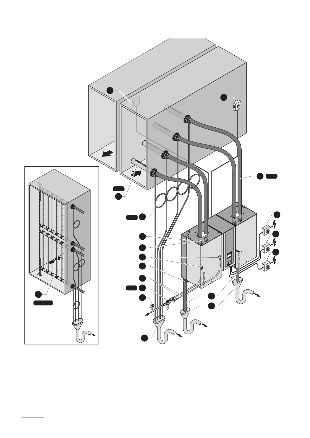
1 Steam humidier
2 Steam connector
3 Water supply connector
4 Water drain connector
5 Water connection hose G 3/4" G 3/8"
(included in the delivery)
6 Filter valve (accessory “Z261”)
7 Manometer (installation recommended)
8 Funnel with siphon (building side)
13
KS10
1
2
3
4
5
Z261
6
7
9
8
125...1250 µS/cm
1...10 bar
1...40 °C
9 Water drain hose (included in the delivery)
10 Service switch control voltage supply (building side)
11 Service switch heating voltage supply (building side)
12 Steam hose (accessory “DS22”/“DS35”)
13 Condensate hose (accessory “KS10”)
14 Steam distribution pipe (accessory “DV41..”/“DV71..”)
15 Steam distribution system (accessory “MultiPipe”)
16 Continuous humidity controller or humidistat
17 Safety humidistat
10
ONOFF
ONOFF
11
13
System overview duct humidication (double units)
17
18
13
DS35
16
MultiPipe
System 4
DV71
15
KS10
Z261
125...1250 µS/cm
1...10 bar
1...40 °C
14
10
ONOFF
1
2
11
ONOFF
12
3
4
ONOFF
5
6
7
9
8
8
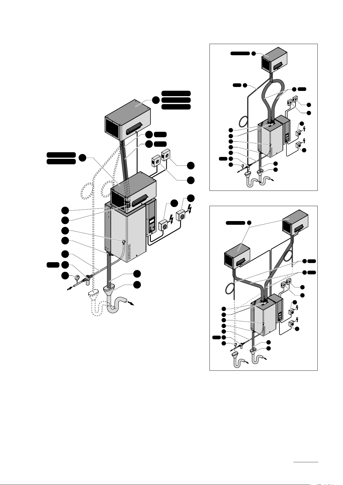
1 Steam humidier
2 Steam connector
3 Water supply connectors
4 Water drain connector
5 Water connection hose G 3/4" G 3/8"
(included in the delivery)
6 Filter valve (accessory “Z261”)
7 Manometer (installation recommended)
8 Funnel with siphon (building side)
9 Water drain hose (included in the delivery)
14
10 Service switch control voltage supply (building side)
11 Service switch heating voltage supply module A (building side)
12 Service switch heating voltage supply module B (building side)
13 Steam hose (accessory “DS35”)
14 Condensate hose (accessory “KS10”)
15 Steam distribution pipe (accessory “DV71..”)
16 Steam distribution system (accessory “MultiPipe”)
17 Continuous humidity controller or humidistat
18 Safety humidistat
System overview room humidication (single units)
FAN4 N S ... D
FAN4 N M ... D
1
2
3
14
14
12
13
FAN4 N S ... W
FAN4 N M ... W
FAN4 N L ... W
DS80
KS10
10
ONOFF
15
Z261
FAN4 N L ... W
KS10
1
2
3
4
5
6
7
14
13
9
8
DS80
12
15
16
10
ONOFF
ONOFF
11
16
11
ONOFF
FAN4 N L ... W
14
4
5
Z261
6
7
125...1250µS/cm
1...10bar
1...40°C
1 Steamhumidier
2 Steamconnector
3 Watersupplyconnector
4 Waterdrainconnector
5 WaterconnectionhoseG3/4"-G3/8"
6 Filtervalve(accessory“Z261”)
7 Manometer(installationrecommended)
8 Funnelwithsiphon(buildingside)
(includedinthedelivery)
KS10
13
DS80
9
8
1
2
3
4
5
Z261
6
7
9
8
12
15
16
10
ONOFF
ONOFF
11
9 Waterdrainhose(includedinthedelivery)
10 Serviceswitchcontrolvoltagesupply(buildingside)
11 Serviceswitchheatingvoltagesupply(buildingside)
12 Steamhose(accessory“DS80”)
13 Condensatehose(accessory“KS10”)
14 Ventilationunit(accessory“FAN4N...”)
15 Continuoushumiditycontrollerorhumidistat
16 Safetyhumidistat
15

System overview room humidication (double units)
FAN4 N L ... W
13
14
15
DS80
KS10
13
14
DS80
KS10
16
17
10
ONOFF
11
ONOFF
1
2
12
ONOFF
3
4
5
Z261
6
7
9
8
125...1250 µS/cm
1...10 bar
1...40 °C
1 Steam humidier
2 Steam connector
3 Water supply connectors
4 Water drain connector
5 Water connection hose G 3/4" G 3/8"
(included in the delivery)
6 Filter valve (accessory “Z261”)
7 Manometer (installation recommended)
8 Funnel with siphon (building side)
KS10
14
FAN4 N L ... W
15
13
DS80
1
2
3
4
5
Z261
6
7
FAN4 N L ... W
9
8
15
16
17
ONOFF
10
ONOFF
11
ONOFF
12
9 Water drain hose (included in the delivery)
10 Service switch heating voltage supply (building side)
11 Service switch heating voltage supply module A (building side)
12 Service switch heating voltage supply module B (building side)
13 Steam hose (accessory “DS80”)
14 Condensate hose (accessory “KS10”)
15 Ventilation unit (accessory “FAN4 N...”)
16 Continuous humidity controller or humidistat
17 Safety humidistat
16

3.6 Options
Nordmann AT4...
522
524
532
534
Remote operating and fault indication
PCB with relay contacts for the connection
of remote displays for “Operation”, “Steam”,
“Fault” and “Service”.
Overpressure set
Kit for mounting the water cup to the unit
cover when operating the steam humidi ers
in systems with a duct air pressure of up to
10 kPa.
Steam hose connector with
condensate trap
Cable glands 1xCG 2xCG 1xCG 2xCG
Internal control voltage supply
(for mains supply with neutral lead)
Transformer 400V/230V for internal
control voltage supply
(for mains supply without neutral lead)
@-Link AT4
Gateway to connect the Nordmann AT4 to a
building management system. Two versions
are available: BACnet/IP or LonWorks.
822
824
832
834
1xS-CVI 1xM-CVI 1xL-CVI
1532
1534
1xCT.. 2xCT.. 4xCT..
2362
2364
1xOPS 2xOPS 1xOPS 2xOPS
Conguration according to separate documentation
3262
3264
4564 4662 6462
6464
1xRFI
Trafo
6564 9064 13064
Steam cylinder for low water conductivity
from 80 to 125 µS/cm
Nordmann AT4... (400 V/3~/50...60 Hz)
534 834 1534 2364 3264 4564 --- 6464 6564 9064 13064
1x
534A-L1x834A-L1x1534A-L1x2364A-L1x3264A-L1x4564A-L
--- 2x
3264A-L
--- 2x
4564A-L
---
17
3.7 Accessories
3.7.1 Accessories overview
Accessories for water installation
Nordmann AT4...
522
524
532
534
Filter valve Z261 (1 pc. per system)
Accessories for steam installation
522
524
532
534
Steam distribution pipe
(Details see chapter 3.7.2)
Steam distribution system MultiPipe
(Details see chapter 3.7.2)
Fan unit
(Details see chapter 3.7.2)
Steam hose / meter DS22
EcoTherm Insulation hose / meter ECT22 (DS22)
Condensate hose / meter KS10
––– ––– System 1 System 2 System 4
DS80 (FAN4 N...)
ECT80 (DS80)
822
824
832
834
822
824
832
834
1xDV41 1xDV71 2xDV71 4xDV71
1x
FAN4 N S D
or
FAN N S W
or
or
1532
1534
1532
1534
1x
FAN4 N M D
or
FAN N M W
2362
2364
2362
2364
3262
3264
Nordmann AT4...
3262
3264
1x
FAN4 N
L W
4564 4662 6462
4564 4662 6462
1x or 2x
FAN4 N
L W
DS80 (FAN4 N...)
ECT60 (DS35)
ECT80 (DS80)
DS35
oder
or
6464
6464
2x
FAN4 N L W
6564 9064 13064
6564 9064 13064
4x
FAN4 N L W
Accessories for humidity control
Nordmann AT4...
522
524
532
534
Duct humidistat NHD (1 pc. per system)
Room humidistat NHR (1 pc. per system)
Humidity sensor for duct installation NDC (1 pc. per system)
Humidity sensor for room installation NRC (1 pc. per system)
822
824
832
834
1532
1534
2362
2364
3262
3264
4564 4662 6462
6464
General accessories
Nordmann AT4...
522
524
532
534
All-weather protective housing Layout according to the separate data sheet
Remote Terminal 1 Terminal for the remote control of up to 8 humidiers
822
824
832
834
1532
1534
2362
2364
3262
3264
4564 4662 6462
6464
6564 9064 13064
6564 9064 13064
18

3.7.2 Accessory details
3.7.2.1 Steam distribution pipe DV41-.../DV71-...
The steam distribution pipes are selected on the basis of the duct width
(for horizontal installation) or the duct height (for vertical installation) and
the capacity of the steam humidier.
Important! Always select the longest possible steam distribution pipe (opti
mum humidication distance).
L
B
Steam distribution pipes for
Nordmann AT4
Type DV41-.. Type DV71-.. in mm
41200 200 210...400
41350 71350 350 400...600
41500 71500 500 550...750
41650 71650 650 700...900
41800 71800 800 900...1100
411000 711000 1000 1100...1300
411200 711200 1200 1300...1600
711500 1500 1600...2000
711800 1800 2000...2400
712000 2000 2200...2600
712300 2300 2500...2900
712500 2500 2700...3100
1)
Material: CrNi steel
1)
2)
Length (L) steam
distribution pipe
2)
special length on request
Duct width (B)
in mm
Note: If the humidication distance (see chapter 5.4.2) has to be reduced for
technical reasons, the amount of steam per unit must be divided between
several steam distribution pipes or the steam distribution system Mul-
tiPipe must be used. If this is the case, contact your Nordmann supplier.
19

3.7.2.2 MultiPipe steam distribution system
H
B
The MultiPipe steam distribution system is used in ventilation ducts with a
short humidication distance (for the calculation of the humidication dis
tance refer to chapter 5.4.2). When ordering an MultiPipe system the duct
dimension must be specied. Please consult the data in the following table.
MultiPipe Number of steam
connectors
System 1 1 32 (23)
System 2 2 65 (45) 4502200 4502200
System 4 4 130 (90) 4502500 8003200
1)
For duct widths <600 mm the value in brackets apply
Max. steam
capacity
in kg/h
1)
Duct dimensions
Width B
in mm
4501500 4501650
Height H
in mm
20

3.7.2.3 Fan units FAN4 N...
The fan units FAN4 N... – in combination with the steam humidiers Nor
dmann AT4 – are used for direct room humidication. The fan units FAN4
N S D and FAN4 N M D are mounted directly on the humidier. The fan
units FAN4 N S W, FAN4 N M W und FAN4 N L W are mounted separately
above the humidier to the wall.
The type and number of fan units are dependent on the steam capacity
and on the type of the humidier and can be gathered from the table in
chapter 3.7.1.
Note: Further information on the fan units FAN4... can be found in the sepa
rate manual supplied with the fan unit.
Important note regarding the IP protection class: If a Nordmann AT4
with fan unit FAN4 N... shall be operated without the fan unit at a later date
(e.g. retrotting for duct humidication) the open bores in the housing ceil
ing must be sealed with plugs, otherwise the protection class IP21 is not
assured anymore.
21

3.8 Standard delivery
The standard delivery includes:
– Steam humidier Nordmann AT4 with water connection hose G 3/4"
G 3/8" and water drain hose ø 31/40 mm equipped with the options
ordered according to chapter 3.6, xing set, mounting instructions (this
document) and operating instructions, packaged in cardboard box
Unit type Dimensions packaging (L x W x D) Transport weight
522, 524, 532, 534,
822, 824, 832, 834
1532, 1534,
2362, 2364
3262, 3264,
4564, 6564
4662,
6462, 6464,
9064, 13064
720 mm x 520 mm x 340 mm 14.0 kg
760 mm x 600 mm x 420 mm 19.5 kg
780 mm x 650 mm x 420 mm 31.0 kg
1045 mm x 430 mm x 820 mm 59.0 kg
– Ordered accessories with operating instructions according chapter 3.7,
packed separately
– Spare parts list
3.9 Storing/Transportation/Packaging
Storing
Store the unit in a protected area meeting the following requirements:
– Room temperature: 1 ... 40 °C
– Room humidity: 10 ... 75 %rh
Transportation
For optimum protection always transport the unit in the original packaging.
The weight of the units with a steam capacity of more than 8 kg/h is more
than 20 kg (see chapter 6.1 “Technical data”). Therefore, always transport
these units with the help of another person or use an appropriate lifting
device. Always place the unit on its back side.
Packaging
Keep the original packaging of the Nordmann AT4 for later use.
In case you wish to dispose of the packaging, observe the local regulations
on waste disposal. Never dispose of the packaging to the environment.
22

4 Notes for the planning engineer
4.1 Selecting the unit version
To select the unit version the following planning steps are required:
1. Calculating the required maximum steam capacity according chapter
4.1.1
2. Selecting the unit version from the table in chapter 4.1.2
4.1.1 Calculating the maximum required steam capacity
The maximum required steam capacity must be calculated based on one
of the following formulas:
V • ρ
mD = • (x2 - x1)
1000
mD: maximum steam demand in kg/h
V: volume of supply air portion per hour in m3/h (for indirect room humidi
cation) or room volume to be humidied per hour in m3/h (for direct
room humidication)
ρ: specic gravity of air in kg/m
ε: specic volume of air in m3/kg
x2: desired absolute room air humidity in g/kg
x1: minimum absolute supply air humidity in g/kg
The values for ρ, ε, x
Carrier-Diagram for moist air respectively.
Important notes:
– The required maximum steam capacity depends on the specic ap
plication and the installation. The calculated steam capacity based on
the above formulas, the h,x diagram and the condition of the air to be
humidied does not consider any steam loss (e.g. due to condensation
in the steam hoses and the steam distributors), any heat loss of the unit
as well as any absorption or release of humidity of materials located in
the room being humidi ed.
In addition, the calculated steam capacity does not consider any losses
caused by the draining rate depending on the water quality as well as
any losses occur if the steam humidier is operated on a mains circuit
with a ground fault circuit interrupter.
and x1 can be gathered from the h,x-diagram or the
2
or
3
V
mD = • (x2 - x1)
1000 • ε
The total amount of losses depends on the entire system and must be
taken into consideration when calculating the required steam capacity. If
you have any questions regarding the calculation of the steam capacity
please contact your Nordmann supplier.
– For systems where the max. required steam capacity varies extensively
(e.g. for test facilities or for systems with variable air volume ow, etc.),
please contact your Nordmann supplier.
23

4.1.2 Selecting the unit
Nordmann AT4 4564 400V3
Heating voltage ** Max. steam ca-
pacity
in kg/h
5 534 x
8 834 x
15 1534 x
23 2364 x
400V3
(400 V/3~/50...60 Hz)
400V2
(400 V/2~/50...60 Hz)
230V3
(230 V/3~/50...60 Hz)
230V1
(230 V/1~/50...60 Hz)
32 3264 x
45 4564 x
64 6464 x
65 6564 x
90 9064 x
130 13064 x
5 524 x
8 824 x
5 532 x
8 832 x
15 1532 x
23 2362 x
32 3262 x
46 4662 x
64 6462 x
5 522 x
8 822 x
Model
Nordmann AT4
Unit size
Single
unit
small medium large large
Double
unit
** Other heating voltages on request
4.2 Selecting the options an accessories
For selecting the options and accessories see chapter 3.6 and 3.7.
24

4.3 Selecting the control system
The various control systems
– System 1: Room humidity control
System 1 is suited for direct room humidication and air condition-
ing systems with mainly recirculated air. The humidity sensor or
humidistat respectively is preferably located in the room itself or in the
exhaust air duct.
A1 humidity sensor
B1 ventilation interlock
B2 airow monitor
B3 safety humidistat
B4 humidistat
PII Internal P/PI controller
PIE External continuous controller
(e.g. PI controller)
Y input signal from A1
AT4
– System 2: Room humidity control with continuous limitation of the
supply air humidity
System 2 is suited for air conditioning systems with a large portion of
supply air, low supply air temperature, post-humidication, or vari-
able airow volume
. If the supply air hum idity exceeds the preset value,
the continuous limitation is effected prior to the room hum idity control.
The humidity sensor (A1) is preferably located in the exhaust air duct
or in the room itself. The humidity sensor (A2) for the limitation of the
supply air humidity is located in the supply air duct after the steam dis
tribution pipe. This control system requires a continuous controller with
the option to connect a second humidity sensor.
Attention! The continuous limitation of the supply air humidity is no
substitute for the safety humi distat.
A1/2 humidity sensor
B1 ventilation interlock
B2 airow monitor
B3 safety humidistat
PII Internal P/PI controller
PIE External continuous controller
(e.g. PI controller)
Y input signal from A1
Z input signal from A2
AT4
25

– System 3: Supply air humidity control with continuous output limit-
ation
Supply air humidity control (humidity sensor installed in supply
air duct) should be used only where room humidity control is
impracticable for technical reasons. Such systems always require
a PIcontroller.
The humidity sensor (A1) is located in the supply air duct after the steam
distribution pipe. The humidity sensor (A2) for the continuous output
limitation is located in the supply air duct before the steam distribution
pipe. Such a system requires a PIcontroller with the option to connect
a second humidity sensor.
A1/2 humidity sensor
B1 ventilation interlock
B2 airow monitor
B3 safety humidistat
PII Internal PI controller
PIE External PI controller
Y input signal from A1
Z input signal from A2
AT4
Which humidity control system for which application?
Application Location of the humidity sensor
room or exhaust air duct supply air duct
Air conditioning systems with:
– supply air portion up to 33% System 1 System 1
– supply air portion up to 66% System 1 or 2 System 2 or 3
– supply air portion up to 100% System 2 System 3
– supply air humidity control — System 3
Direct room humidication System 1 —
Please contact your Nordmann supplier, if your application meets the
following conditions:
– Humidication of small rooms up to 200 m
3
– Air conditioning systems with a high number of air exchanges
– Systems with variable air volume ow
– Test facilities with extreme control accuracy requirements
– Rooms with a high variation in max. steam capacity
– Systems with temperature uctuations
– Cold rooms and systems with dehumidication
26
Admissible input signals
see chapter 6.1 “Technical data”

5 Mounting and installation work
5.1 Important notes for mounting and installation work
Qualication of personnel
All mounting and installation work must be carried out only by well qualied personnel authorised by the owner. It is the owner’s responsibility
to verify proper qualication of the personnel.
General note
Strictly observe and comply with all information given in the present mounting
instructions regarding the location of the unit and the installation of water,
steam and electricity.
Observe and comply with all local regulations dealing with water, steam
and electrical installations.
Safety
Some installation work requires removal of the unit covers. Please note
the following:
DANGER!
Danger of electric hazard!
You may get in touch with live parts when the unit is open. The steam
humidier must be connected to the mains only after all mounting and
installation work has been completed and the cover has been relocated
properly.
CAUTION!
The electronic components inside the humidier are very sensitive to
electrostatic discharge. When the unit is open for installation work, ap
propriate measures must be taken to protect these components against
damage caused by electrostatic discharge (ESD protection).
27

5.2 Installation overviews
Installation overview duct humidication
A1 / A2
DV41
DV71
Pmax 1500 Pa
Pmin -800 Pa
Steam installation
see chapter 5.4
Mounting the unit
see chapter 5.3
min. 300 mm
min. 20 %
–
min. 5 %
KS10
–
Rmin. 300 mm
Ømin.
200 mm
DS22
DS35
min. 20 %
min. 300 mm
Heating voltage **
K1
L1 L2 L3
PE
AT4
ext.
B3
Q5
XE1
L1 L2 L3
F5
L1 L2 L3
400 V/3~/50..60 Hz
230 V/3~/50..60 Hz
PE
Q5
F5
L1 L2
400 V/2~/50..60 Hz
PE
Q5
** on double units each
module has a separate
heating voltage supply
+
F5
L1 N PE
230 V/1~/50..60 Hz
Control voltage
N
L1
XE3
Q6
PE
AT4
ext.
F6
L1 N PE
ONOFF
Q6
230 V/1~/50..60 Hz
External safety chain
Water installation
see chapter 5.5
125...1250 µS/cm
Electric installation
see chapter 5.6
28
G 1/2"
1...10 bar
1...40°C
G 3/4"
ø 31 mm
ø 14/7 mm
Z261
G 3/8"
≥ 40 mm
min. 50 cm
Continuous
control
XE4
A1
V+
+ –
P / PI
ONOFF
Q5
SC1
SC2
J
XE2
max.
∆p
AT4
ext.
B3
B2
B1
Ohmic humidity
controller
24V 5V
JP3
IN
XE4
GND
AT4
ext.
A2
IN
V+
140Ω...10kΩ
GND
AT4
ext.
24V On/Off
controller
JP3
XE4
A3
24V 5V
V+
On/Off
Z signal
LIM. SIGN.
GNDIN
IN
GND
AT4
ext.
X11
AT4
ext.
+ –
A4
P / PI

System overview room humidication
** on double units each
module has a separate
heating voltage supply
Heating voltage **
K1
L1 L2 L3
Steam installation
see chapter 5.4
Mounting the unit
see chapter 5.3
Ø min.
100 mm
KS10
min. 20 %
–
Ø min.
100 mm
FAN4 N S ... W
FAN4 N M ... W
FAN4 N L ... W
min. 20 %
DS80
min. 20 %
KS10
–
B3
A1 / A2
FAN4 N S ... D
FAN4 N M ... D
Q6
PE
AT4
ext.
Q5
XE1
L1 L2 L3
F5
L1 L2 L3
400 V/3~/50..60 Hz
230 V/3~/50..60 Hz
PE
Q5
+
F5
L1 L2
400 V/2~/50..60 Hz
PE
Q5
F5
L1 N PE
230 V/1~/50..60 Hz
Control voltage
N
L1
L1 N
XE3
Q6
PE
AT4
ext.
F6
ONOFF
FAN4 N ...
L1 N PE
230 V/1~/50..60 Hz
Water installation
see chapter 5.5
125...1250 µS/cm
Electric installation
see chapter 5.6
G 1/2"
1...10 bar
1...40°C
G 3/4"
ø 31 mm
ø 14/7 mm
Z261
G 3/8"
≥ 40 mm
min. 50 cm
Q5
ONOFF
Continuous
control
XE4
V+
A1
+ –
P / PI
IN
GND
AT4
ext.
External safety chain
Ohmic humidity
controller
24V 5V
JP3
IN
XE4
V+
GND
AT4
ext.
A2
140Ω...10kΩ
SC1
SC2
J
XE2
XE4
A3
AT4
ext.
B3
max.
∆p
B2
B1
24V On/Off
controller
24V 5V
JP3
IN
V+
On/Off
GND
AT4
ext.
29

5.3 Mounting the unit
5.3.1 Notes on locating the unit
min. 400 mm
min. 250 mm
Y
min. 400 mm
X
Z
Nordmann AT4 ...
522
524
532
534
822
824
832
834
min. 600 mm
1532
1534
2362
2364
min. 600 mm
3262
3264
4564 4662 6462
6464
6564 9064 13064
30
Dimensions
Housing dimensions
in mm
Weights
Net weight in kg 12 12 19 19 28 28 62 62 30 64 64
Operating weight in kg 17 17 29 29 65 65 116 116 67 116 116
X 388 388 468 468 563 563 966 966 563 966 966
Y 255 255 345 345 354 354 354 354 354 354 354
Z 575 575 620 620 640 640 640 640 640 640 640

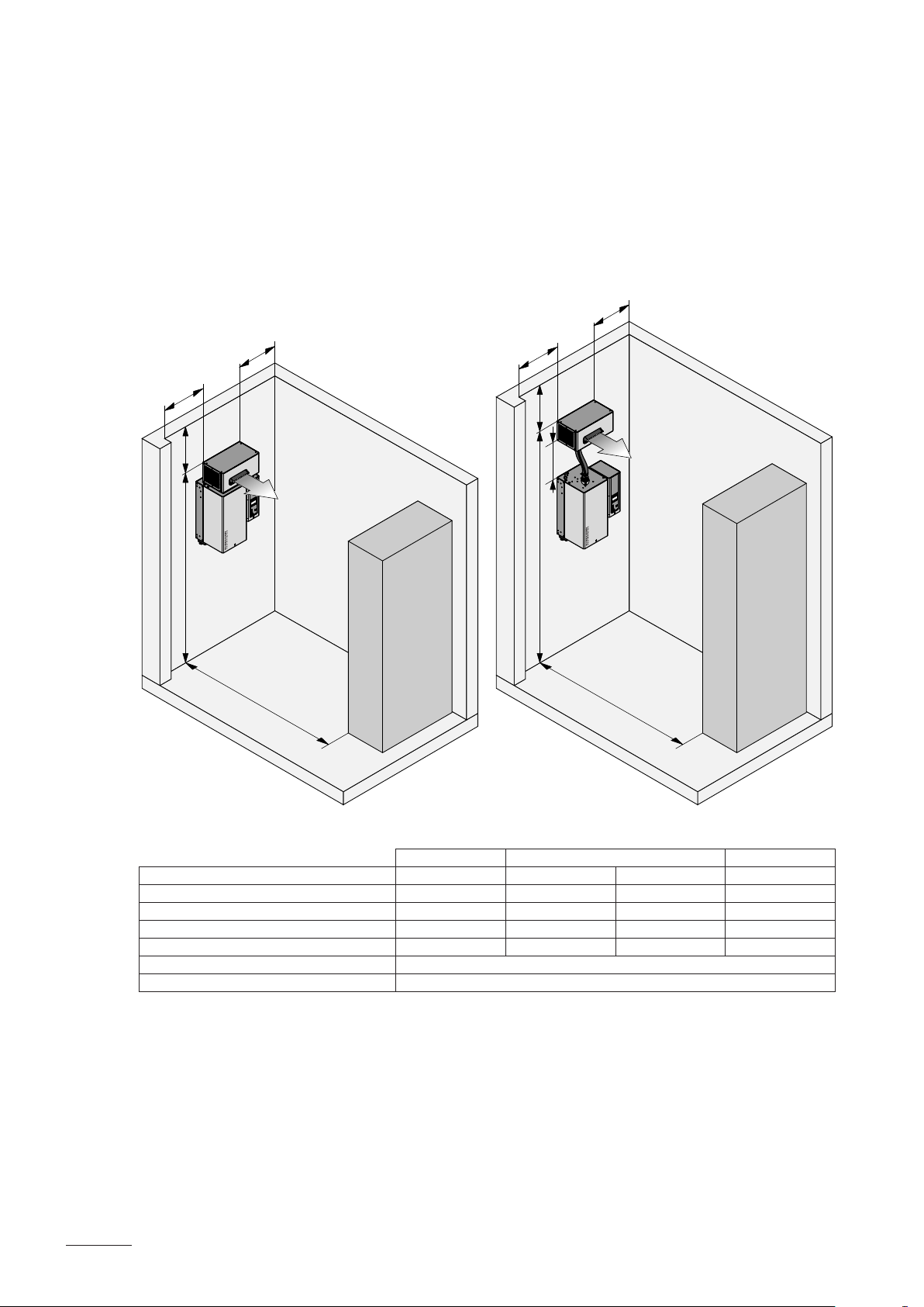
The installation site of the steam humidier depends largely on the location
of the steam distributor (see chapter 5.4). To ensure proper functioning
of the steam humidier and to obtain an optimal efciency, the following
points must be considered and observed when choosing the location for
the steam humidier:
– Install the steam humidier so that the length of the steam hose is kept
as short as possible (max. 4 m) and that the minimum bend radius
(R= 300 mm) and up-slope (20 %) or down-slope (5 %) of the steam
hose is observed (see chapter 5.4.5).
– The steam humidiers Nordmann AT4 are designed for wallmount
ing. Make sure that the construction (wall, pillar, oormounted console,
etc.) to which the humidiers are to be mounted, offers a sufciently
high load-bearing capacity (take notice of the weight information
found in the dimensions and weights table above), and is suitable for
the installation.
CAUTION!
Do not mount the steam humidier directly to the ventilation duct
(insufcient stability).
– The back panel of the Nordmann AT4 is retaining heat during operation
(max. surface temperature of the metal housing approx. 60 70 °C).
Make sure, therefore, that the construction (wall, pillar, etc.) to which
the unit is to be mounted, does not consist of heatsensitive material.
– Install the steam humidier in such a manner that it is freely accessible
with sufcient space available for maintenance purposes (refer to the
above illustration for minimum distances).
– The Nordmann AT4 is protected according to IP21. Make sure the units
are installed in a dripproof location and the admissible ambient condi
tions are complied with.
– The steam humidier Nordmann AT4 may only be installed in rooms
with a oor drain.
CAUTION!
If for some reason the Nordmann AT4 must be installed in a location
without oor drain, it is mandatory to provide a leakage monitoring
device to safely interrupt the water supply in case of leakage.
– When xing the Nordmann AT4 use only the xing materials supplied
with the unit. If xing with the materials supplied is not possible in your
particular case, select a method of xing that is of similar stability.
– The Nordmann ES4 is designed for installation and operation within
buildings (admissible temperature range see chapter 6.1). For outdoor
operation the Nordmann AT4 must be placed in a weather protective
housing. If ambient temperatures near or below the freezing point have
to be expected, the protective housing must equipped with a thermostat
controlled heating of sufcient capacity. The water supply pipe must be
equipped with a traceheating and must be insulated up to the protective
housing.
31

5.3.2 Mountingthehumidier
b
c
b
a
A
A
Dimension Unit type
522, 524,
532, 534,
822, 824,
832, 834
a 204,0 mm 205.0 mm 205.0 mm
b 40,0 mm 50.0 mm 52.5 mm
c 150,0 mm 210.0 mm 260.0 mm
BB
1532, 1534,
2362, 2364
3262, 3264,
4564, 6564
Dimension Unit type
4662, 6462, 6464, 9064, 13064
b
c
A
d
A
d
A
c
A
b
a
A
BB
a 203.0 mm
b 43.5 mm
c 258.0 mm
d 181.5 mm
B
B
32

Procedure
1. Mark the attachment points “A” for the wall support at the desired position
with the help of a spirit level. Then, drill holes diameter: 8 mm, depth:
40 mm.
2. Insert the supplied plastic plugs, and x the wall support to the wall with
the screws supplied. Before thightening the screws adjust wall support
horizontally using a spirit level.
3. Unlock the screw(s) of the front panel(s) (steam side), then remove the
front panel(s).
4. Unmount the steam cylinder(s) (see Nordmann AT4 operating instruc
tions chapter 6.3.1).
5. Hang up the unit onto the wall support. Then, x the unit to the wall
support using the supplied screws “B”.
6. Remount the steam cylinder(s) (see Nordmann AT4 operating instruc
tions chapter 6.3.1).
7. Reattach the front panel(s) and secure it with the screw(s).
5.3.3 Inspecting the installed unit
Check the following points:
Is the unit installed in the correct place (see chapter 5.3.1)?
Is the supporting surface stable enough?
Is the unit correctly aligned, vertically and horizontally?
Is the unit properly secured (see chapter 5.3.2)?
Has/have the front panel(s) of the unit been relocated and correctly xed
with the screw(s)?
33

5.4 Steam installation
5.4.1 Overview steam installation
DV41
DV71
Pmax 1500 Pa
Pmin -800 Pa
FAN4 N S ... W
FAN4 N M ... W
FAN4 N L ... W
DS80
KS10
min. 20 %
min. 20 %
–
min. 300 mm
+
min. 20 %
–
KS10
min. 5 %
200 mm
–
Rmin. 300 mm
Ømin.
DS22
DS35
min. 20 %
min. 300 mm
+
34
Ø min.
100 mm
KS10
min. 20 %
–
Ø min.
100 mm
FAN4 N S ... D
FAN4 N M ... D
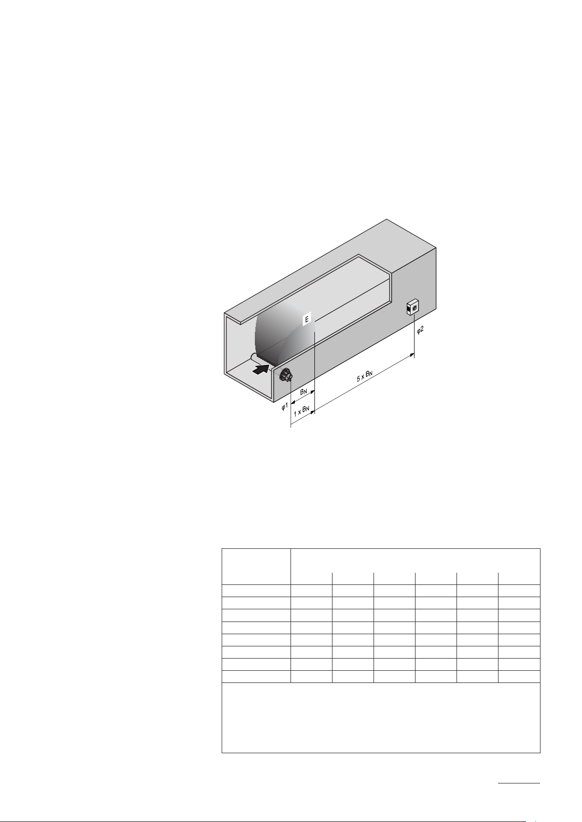
5.4.2 Positioning of the steam distribution pipes
The location for the steam distribution pipes should be determined at the
time of dimensioning the air conditioning system. Please note the following
instructions to ensure proper humidication of the duct air.
Calculating the humidication distance
The water vapour, emitting from the steam distribution pipes, requires a
certain distance to be absorbed by the ambient air so that it is no longer
visible as steam. This distance is referred to as humidication distance
“B
” and serves as a basis for the determination of the minimum distances
N
from the upstream components in the system.
BN: Humidication distance B
E: Expansion and mixing zone
φ1: Supply air humidity before humidication
φ2: Supply air humidity after humidication
N
The calculation of the humidication distance “BN” is dependent on several
factors. For a rough estimation of the humidication distance “BN”, the fol
lowing table is useful. Recommended standard values listed in this table
are based on a supplyair temperature range of 15 °C to 30 °C. The values
given in bold type only apply to steam distribution pipes DV41-... and
DV71-..., the values in brackets apply to the MultiPipe steam distribution system.
Humidity at inlet
ϕ1 in %rh
40 50 60 70 80 90
5 0,9 (0,22) 1,1 (0,28) 1,4 (0,36) 1,8 (0,48) 2,3 (0,66) 3,5 (1,08)
10 0,8 (0,20) 1,0 (0,26) 1,3 (0,34) 1,7 (0,45) 2,2 (0,64) 3,4 (1,04)
20 0,7 (0,16) 0,9 (0,22) 1,2 (0,30) 1,5 (0,41) 2,1 (0,58) 3,2 (0,96)
30 0,5 (0,10) 0,8 (0,17) 1,0 (0,25) 1,4 (0,36) 1,9 (0,52) 2,9 (0,88)
40 – 0,5 (0,11) 0,8 (0,20) 1,2 (0,30) 1,7 (0,45) 2,7 (0,79)
50 – – 0,5 (0,13) 1,0 (0,24) 1,5 (0,38) 2,4 (0,69)
60 – – – 0,7 (0,16) 1,2 (0,30) 2,1 (0,58)
70 – – – – 0,8 (0,20) 1,7 (0,45)
φ1 in %rh: Relative supply air humidity prior to humidication at the lowest supply air
temperature
φ2 in %rh: Relative supply air humidity after the steam distribution pipe at maximum
capacity
For duct widths <600 mm the humidication distance for the MultiPipe system increases
by approx. 50%
Length of humidication distance BN in m
Humidity at outlet ϕ2 in %rh
35

Example
given: ϕ1= 30 %rh, ϕ2= 70 %rh
humidication distance B
(0.36 m for steam distribution system MultiPipe)
Note: If the humidication distance has to be reduced for technical reasons,
the amount of steam per unit must be divided between several steam
distribution pipes or the steam distribution system MultiPipe must be
used. If this is the case, contact your Nordmann supplier.
Minimum distances to be observed
To prevent the water vapour, that is emitting from the steam distribution pipe,
from condensing on downstream system components, a minimum distance
to the steam distribution pipe must be observed (depends on the humidi
cation distance “BN”).
before/after constriction
50 mm
N
0.5 x B
: 1,4 m
N
after expansion
N
0.5 x B
before bend
N
1 x B
before branch
N
1 x B
36

before diffuser
N
1 x B
before control sensor
N
5 x B
before/after lter/register before/after fan, zone exit
N *
1.5 x B
* 2,5 x BN before aerosol lter
+
50 mm
1 x B
50 mm
N
1 x B
N
Installation notes and dimensions
The steam distribution pipes are designed for either horizontal installation
(on the duct wall) or, with accessories, for vertical installation (in the duct
oor). The outlet orices should always point upwards and at right
angles to the airow.
If possible, the steam distribution pipes should be installed on the pressure
side of the duct (max. duct pressure 1500 Pa). If the steam distribution
pipes are installed on the suction side of the duct, the maximum vacuum
must not exceed 800 Pa.
Select a location for the installation, tailored to suit your duct (see the fol
lowing illustrations) and position the steam distribution pipes in the duct so
that a uniform distribution of steam is achieved.
37

Positioning the steam distribution pipes in the duct
In positioning the steam distribution pipes, the following dimensions should
be observed:
H
1/2
1/2
2/3
H
1/3
min
h
H
1/2
1/2
H min.= 250 mm H ≥400 mm H min.= 200 mm
1/3
1/3
1/3
H min.= 300 mm
H
H min.= 400 mm
3/7
2/7
2/7
min
g
3/7
H
2/7
2/7
H min.= 350 mm
H
H
H min.= 720 mm
g min.= 100 mm
h min.= 85 mm
2/6
1/6
1/6
1/6
1/6
1/5
min
g
min
g
min
g
2/6
1/6
1/6
H
1/6
1/6
H min.= 600 mm
1/5
1/5
1/5
1/5
H min.= 500 mm
H
38

Note: When locating the MultiPipe steam distribution system please note
the instructions in the separate documentation for this product.
Guidelines for dimensioning the ventilation ducts
– To facilitate the installation of the steam distribution pipes and for control
purposes, a sufciently sized control opening should be planned.
– Within the range of the humidication distance, the ventilation duct
should be waterproofed.
– Air ducts passing through cold rooms should be insulated to prevent
the humidied air from condensing along the duct wall.
– Poor airow conditions within the air duct (e.g. caused by obstacles,
tight bends, etc.) can lead to condensation of the humidied air.
– Steam distribution pipes must not be mounted to round ducts.
If you have questions relating to the dimensioning of ventilation ducts in
combination with steam humidiers Nordmann AT4, contact your Nordmann
supplier.
5.4.3 Installing the steam distributors
Detailed information on the installation of steam distribution pipes DV41
.., DV71... and MultiPipe steam distribution system can be found in the
separate mounting instructions for these products.
39
5.4.4 Positioning and mounting of the fan units FAN4 N...
Fan unit FAN4 N...
The fan units FAN4 N S D and FAN4 N M D are mounted directly on the
humidier. The fan units FAN4 N S W, FAN4 N M W und FAN4 N L W are
mounted separately above the humidier to the wall. To allow the steam
coming from the fan unit to spread out evenly, without condensing on obsta
cles (ceilings, joists, pillars, etc.), the following minimum dimensions must
be observed when selecting the location for the fan unit.
D
D
D
B
C
A
D
B
E
C
A
40
FAN4 N S W FAN4 N M W FAN4 N L W
max. 8 kg/h 15 kg/h 23 kg/h 45 kg/h
m
D
A min. 4.0 m 6.0 m 8.0 m 10.0 m
B min. 1.0 m 1.0 m 1.0 m 1.5 m
C approx. 2.2 m 2.2 m 2.2 m 2.2 m
D approx. 1.0 m 1.0 m 1.0 m 1.5 m
E min. 1.0 m
E max. (max. steam hose length) 4.0 m (recommended: 2.0 m)
Note: The minimum spaces in the table apply for a room atmosphere of
15 °C and max. 60 %rh. For lower temperatures and/or higher humidity the
values should be adjusted accordingly.
Note: In order to achieve a uniform distribution of the humidity within the
room, additional factors such as the room size, the room height, etc., must
be taken into consideration besides observing the minimum distances for
the fan units FAN4 N... If you have questions concerning the direct room
humidication, please contact your Nordmann supplier.
Further information is provided in the separate installation and operating
instructions for the corresponding fan unit.

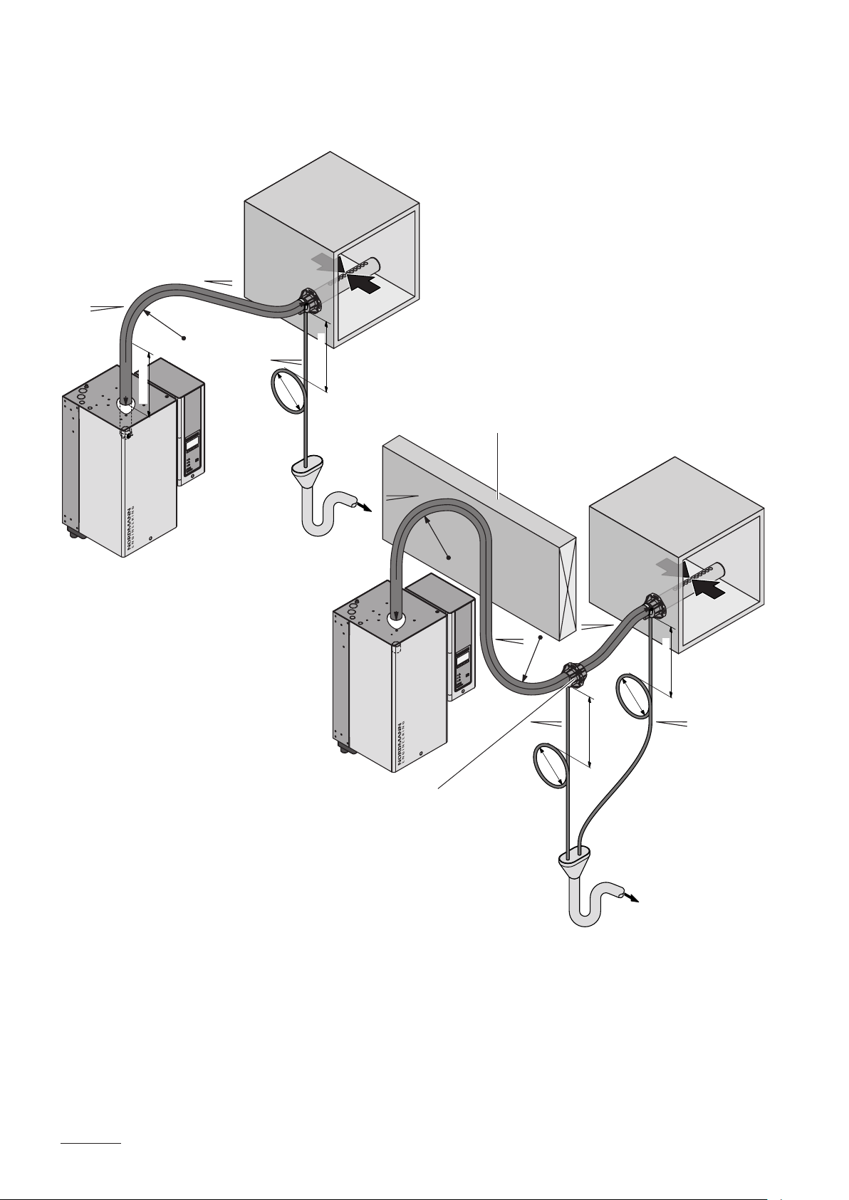
5.4.5 Installing the steam and condensate hose
Important! Use original steam and condensate hose from your Nordmann
supplier exclusively. Other types of hoses can cause undesired operational
malfunctions.
Instructions for the hose layout
The hose layout depends on the position of the steam distribution pipe:
– Steam distribution pipe is mounted more than 500 mm above the top
edge of the humidier:
min. 20 %
+
Ømin. 200 mm
min. 20 %
–
Rmin. 300 mm
min. 300 mm
min. 20 %
max. 4 m
min. 20 %
+
min. 300 mm
Ømin. 200 mm
min. 300 mm
Rmin. 300 mm
max. 4 m
min. 300 mm
–
Initially, lead the steam hose with an upslope of at least 20% over
a minimum height of 300 mm, then lead the hose with a minimum
upslope of 20% and/or a minimum downslope of 5% to the steam
distribution pipe.
The condensate hose is led down to the humidier with a minimum slope
of 20 %, in the form of a
siphon (min. hose bend diameter Ø200 mm)
and is to be connected to the appropriate connector on top of the unit.
Note: If your unit feeds a number of steam distribution pipes, the indi
vidual condensate hoses are to be led into a discharge funnel.
Important! Before putting the unit into operation, the siphon of the
condensate hose must be lled with water.
41
min. 20 %
+
max. 4 m
min. 300 mm
Rmin. 300 mm
min. 5 %
–
– Steam distribution pipe is mounted less than 500 mm above the top
edge of the humidier:
min. 20 %
–
200 mm
Ømin.
min. 300 mm
min. 20 %
Obstacle
+
Rmin. 300 mm
max. 4 m
Install condensate drain (accessory)
at the lowest point
Initially, the steam hose is led with an upslope of at least 20 % over a
minimum height of 300 mm above the top edge of the humidier and
then down to the steam distribution pipe with a minimum slope of 5 %.
min. 5 %
–
Rmin. 300 mm
min. 20 %
–
Ømin.
200 mm
min. 20 %
min. 300 mm
+
min. 300 mm
Ømin.
200 mm
min. 20 %
–
42
The condensate hose is led down with a minimum slope of 20 %, in
the form of a siphon (min. hose bend diameter Ø200 mm), directly
into a discharge funnel.
Important! Before putting the unit into operation, the siphon of the
condensate hose must be lled with water.

– The steam hose should be kept as short as possible (max. 4 m) while
observing the minimum bend radius of 300 mm. Important! Allow
ance must be made for a pressure loss of approx. 100 Pa per meter
steam hose.
Note: If your particular installation exceeds the maximum steam hose
length of 4 m contact your Nordmann representative. In any case, steam
hoses longer than 4 m must be insulated in their entire length (e.g. with
insulation hose “EcoTherm”).
– Reductions in the cross section such as kinks should be avoided through
out the entire length of the hose. The installation of a stop cock in the
steam hose is not permissible.
– Steam hoses must be prevented from sagging (condensate pockets); if
necessary, support with pipe clamps, trough, or wall brackets, or install
a condensate drain in the steam hose.
– Important! When deciding on the length and layout of the hose, it
should be noted that the steam hose may become somewhat shorter
with progressive ageing.
– Important note regarding the IP protection class: to meet the IP21
protection class the steam hose lead through on top of the housing must
be sealed with commercially available, heat resistant sealant.
Securing the hose
The steam hose must be secured to the steam distribution pipe and humidi
er steam outlet by means of hose clamps.
Caution! Do not overtighten the hose clamp on the steam connector of the
steam humidier.
43

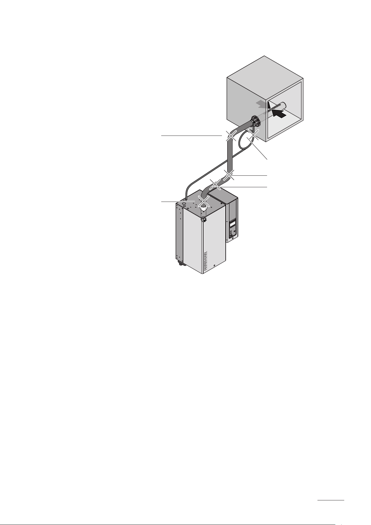
Steam line with xed piping
For steam lines with xed piping, the same instructions apply to the laying
of the piping as already described.
min. 20 %
+
max. 4 m
min. 20 %
Rmin. 5 x D
min. 300 mm
Ømin. 200 mm
min. 300 mm
–
The following additional notes should be observed:
– The minimum internal diameter of the steam line (diameter depend
ent on the steam humidier) should be applied over the whole length of
the piping.
– Use exclusively copper pipe or stainless steel (min. DIN 1.4301).
– To minimize the condensate formation (=loss), the steam pipes must
be insulated.
– The minimum bend radius for solid pipes is 5 x internal diameter.
– Connection of the steam pipes to the steam distribution pipe and steam
humidier is effected by means of short lengths of steam hose secured
with hose clamps.
– Important! Allowance must be made for a pressure loss of approx.
100 Pa per meter length or per 90° bend.
44
5.4.6 Common steam and condensate line errors
2.
1.
3.
4.
5.
1. Steam hose not led at least 300 mm perpendicularly upwards before
rst bend.
2. Minimum bend radius of steam hose of 300 mm not maintained (forming
of condensate).
3. Siphon of the condensate hose not at least 300 mm below the steam
distribution pipe.
4. No condensate drain installed at vertical transition.
5 . Steam hose not sloped (slope min. 20 %).
45

5.4.7 Inspecting the steam installation
Use the following check list to ascertain that the steam installation was
performed correctly:
– Steam distributors
Steam distributors (steam distribution pipe or MultiPipe steam distri
bution system) correctly positioned and secured (screws tightened)?
Are the outlet orices at right angles to the air ow direction?
– Steam hose
Maximum length of 4 m?
Minimum bend radius of 300 mm (5 x internal diameter with xed
piping)?
Have the instructions for hose positioning been followed?
Steam hose: no sagging (condensate pocket) or condensate drain
with siphon (hose bend with a minimum diameter of 200 mm) installed
at the lowest point?
Rigid steam lines: properly insulated? Correct installation material
used? Minimum internal diameter maintained?
Steam hose(s) securely attached with clamps?
Heat expansion during operation and shortening of the hose with
ageing taken into consideration?
Is the lead through of the steam hose on top of the unit sealed
(safeguarding of the IP21 protection)?
– Condensate hose
Downslope of at least 20 %?
Siphon (min. ø200 mm) existing and lled with water?
Condensate hose correctly xed and not kinked?
46

5.5 Water installation
5.5.1 Overview water installation
G 3/4"
ø 31 mm
ø 14/7 mm
G 1/2"
125...1250 µS/cm
1...10 bar
1...40°C
Z261
G 3/8"
≥ 40 mm
ø 31 mm
G 3/4"
min. 50 cm
G 3/8"
G 3/4"
125...1250 µS/cm
1...10 bar
1...40°C
ø 31 mm
ø 14/7 mm
G 1/2"
min. 50 cm
Z261
≥ 40 mm
47

5.5.2 Notes on water installation
Water supply
The water supply is to be carried out according to the gure found in chapter
5.5.1 and the applicable local regulations for water installations. The indicated
connection specications must be observed.
– The installation of the lter valve (accessory “Z261”, alternatively a
shutoff valve and a 5 µm water lter can be used) should be made as
close as possible to the steam humidier.
– Admissible mains pressure 1.0 to 10.0 bar (hammer-free system)
For mains pressures >10 bar, the connection must be made via a pres
sure reducing valve (adjusted to 1.0 bar). For mains pressures <1.0 bar
please contact your Nordmann supplier.
– Notes on water quality:
– For the water supply of the Nordmann AT4, use exclusively untreated
– The use of additives such as corrosion inhibitors, disinfectants,
– If the Nordmann AT4 shall be operated with softened or partly sof
drinking water.
etc. is not allowed, since these additives may endanger health and
affect proper operation.
tened water, please contact your Nordmann supplier.
– The connection material must be pressure-proof and certied for use
in drinking water systems.
– Important! Before connecting the water line, the line should be well
ushed out.
CAUTION!
The thread at the humidier connection is made of plastic. To avoid
overtightening, the union nut of the water pipe must be tightened by
hand only.
Water drain
The water drain is to be carried out according to the gure found in chapter
5.5.1 and the applicable local regulations for water installations. The indi
cated connection specications must be observed.
– Make sure that the drain pipe is correctly xed and easily accessible for
inspections and cleaning purposes.
– The draining temperature is: 80…90 °C. Use temperatureresistant
installation materials only!
– The two drain hoses of a double unit must be led into separate funnels
with siphon.
48

5.5.3 Inspecting the water installation
Check the following topics:
– Water supply
Has lter valve (accessory “Z261”) or shutoff valve and 5 µm water
lter respectively been installed in supply line?
Have admissible water pressure (1 – 10 bar) and admissible tem
perature (1 – 40 °C) been observed?
Does the supply capacity match the humidier and is the minimum
inside diameter of the supply pipe maintained throughout the entire
length?
Are all components and pipes properly secured and are all threaded
connections securely tightened?
Is the water system properly sealed?
Does the water supply installation meet the requirements of the local
regulations for water installations?
– Water drain
Is the minimum inside diameter of the drain pipe of 40 mm maintained
throughout the entire length?
Has drain pipe been installed with a downslope of at least 10 %?
Has the heat resistance of the material used been veried to be at
least 100 °C?
Is the drain hose properly secured (hose clamps at unit connection
tightened)?
Does the water drain installation meet the requirements of the local
regulations for water installations?
49

5.6 Electric installation
5.6.1 Wiring diagram Nordmann AT4 single units
ext.
AT4
PE
PE
PE
Remote Terminal
Unit 2Unit 3Last Unit
L1 L2 L3
K1
X3
L'N
X5
S1S2
LEVEL SENS.
X15
JP5
JP4
JP1
D+ D– GND 5V 24V
X15
JP5
JP4
JP1
D+ D– GND 5V 24V
X15
JP5
JP4
JP1
D+ D– GND 5V 24V
X15
JP5
JP4
JP1
D+ D– GND 5V 24V
CURRENT SENSOR
from contactor to cylinder
X15
F4 315mAT
REMOTE
D+ D– GND 5V 24V
LINK UP
J2
J9
Control board Power board
JP5
JP4
JP1
X4
L'NL'N
X16
L1FUNL1SWNSW
L'N
INLET DRAIN CONTA.
SC
F1 6.3 AT
CONTACTORDRAININLETSC SYSTEM
SAFETY CHAIN
LEVEL SENSOR
GND
24V
F3 315mAT
5V
EXTERNAL CON.CPU BOARD
J4
24V 5V
SWITCH
JP3
X2
PEPESC2SC1NL1
MAIN SUPPLYMODULE B
PEP1NP
EXT. SUP.
5V GND 24V
GNDIN
LIM. SIGN.
GNDINV+
CONT. SIGN.
BAT
X1
X6
X14
X11
X10
J1
J3
L1 L2 L3
N
XE1
XE2XE3XE4
SC2
SC1
PE
L1
IN
V+
GND
Q5
L1 L2 L3
400 V/3~/50..60 Hz
F5
230 V/3~/50..60 Hz
Q5
L1 L2
400 V/2~/50..60 Hz
F5
B3KB2
max.
Q5
∆p
L1 N PE
230 V/1~/50..60 Hz
F5
B1
J
L1 N PE
F6
Q6
230 V/1~/50..60 Hz
M
L1 N
GND
IN
V+
24V 5V
JP3
A2
P / PI
+ –
P / PI
+ –
A1 A4
J2
140Ω...10kΩ
24V 5V
JP3
IN
V+
On/Off
A3
H1
J1
2 3 4 5 6 7 8 9 10
Error Service Steam UnitOn
J1
J4
1
X1
50
24 VDC supply (V+) (315 mA, slow acting)
(315 mA, slow acting)
A1 Continuous controller (active) or humidity sensor
A2 Controller (passive), set jumper on JP35V
A3 On/Off controller, set jumper on JP324V
A4 Limitation signal
BAT Backup battery (CR2032, Lithium 3V)
B1 Ventilation interlock
B2 Safety humidistat
B3 Airow monitor
F1 Internal fuse “Power board” (6.3 A, slow acting)
F3 Internal fuse “Power board” control signal
F4 Internal fuse “Power board”
F5 External fuse heating voltage supply
F6 External fuse control voltage supply
H1 Remote operating and fault indication (option “RFI”)
J Short circuited, if no external monitoring devices
are connected
J2 Link Up system “Power board”
JP1 End resistor Remote Terminal
JP3 Jumper control signal
JP4 Pull up resistor Remote Terminal
JP5 Pull down resistor Remote Terminal
K External safety chain (230V/5A)
K1 Main contactor
M Fan unit
Q5 External service switch heating voltage supply
Q6 External service switch control voltage supply
XE1 Connection terminal heating voltage
XE2 Connection terminal safety chain
XE3 Connection terminal control voltage
XE4 Connection terminal control signal Y
X15 Connection terminal remote panel

5.6.2 Wiring diagram Nordmann AT4 double units
ext.
AT4
PE
PE
PE
Remote Terminal
Unit 2Unit 3Last Unit
L1 L2 L3
K1
Heating Module A
X3
L'N
X5
S1S2
LEVEL SENS.
X15
JP5
JP4
JP1
D+ D– GND 5V 24V
X15
JP5
JP4
JP1
D+ D– GND 5V 24V
X15
JP5
JP4
JP1
D+ D– GND 5V 24V
X15
JP5
JP4
JP1
D+ D– GND 5V 24V
from contactor to cylinder
CURRENT SENSOR
X15
F4 315mAT
JP5
JP4
REMOTE
JP1
D+ D– GND 5V 24V
LINK UP
J2
J9
X4
L'NL'N
X16
L1FUNL1SWNSW
L'N
INLET DRAIN CONTA.
SC
F1 6.3 AT
CONTACTORDRAININLETSC SYSTEM
SAFETY CHAIN
LEVEL SENSOR
GND
24V
F3 315mAT
5V
EXTERNAL CON.CPU BOARD
J4
24V 5V
SWITCH
JP3
X2
PEPESC2SC1NL1
MAIN SUPPLYMODULE B
PEP1NP
EXT. SUP.
5V GND 24V
GNDIN
LIM. SIGN.
GNDINV+
CONT. SIGN.
BAT
X1
X6
X14
X11
X10
J1
J3
L1 L2 L3
N
XE1
XE2XE3XE4
SC2
SC1
PE
L1
GND
IN
V+
Q5
L1 L2 L3
400 V/3~/50..60 Hz
F5
230 V/3~/50..60 Hz
Q5
L1 L2
400 V/2~/50..60 Hz
F5
Q5
B3KB2
max.
∆p
L1 N PE
230 V/1~/50..60 Hz
F5
B1
J
L1 N PE
F6
Q6
230 V/1~/50..60 Hz
M
L1 N
GND
IN
V+
24V 5V
JP3
A2
P / PI
+ –
P / PI
+ –
A1 A4
140Ω...10kΩ
24V 5V
JP3
IN
V+
On/Off
A3
H1
J2
J1
2 3 4 5 6 7 8 9 10
Error Service Steam UnitOn
J1
J4
1
X1
CURRENT SENSOR
X25
S1S2
Extension board Module B Control board Power board
humidity sensor
A1 Continuous controller (active) or
A2 Controller (passive), set jumper on JP35V
A3 On/Off controller, set jumper on JP324V
A4 Limitation signal
CPU BOARD
J3
MAINSC SYSTEM DRAIN INLET
LEVEL SENSOR
MAIN
INLETDRAINSC
LEVEL SENS.
X23
X24
(6.3 A, slow acting)
BAT Backup battery (CR2032, Lithium 3V)
B1 Ventilation interlock
B2 Safety humidistat
B3 Airow monitor
F1 Internal fuse “Power board”
F3 Internal fuse “Power board” control signal
X14
EXT. SUP.
5V GND 24V
PEP1NP
MODULE B
L' N L' N L' N L' N
X6
X27
24 VDC supply (V+) (315 mA, slow acting)
(315 mA, slow acting)
F4 Internal fuse “Power board”
F5 External fuse heating voltage supply
F6 External fuse control voltage supply
L1 L2 L3
Heating Module B
K1
(option “RFI”)
devices are connected
H1 Remote operating and fault indication
J Short circuited, if no external monitoring
J2 Link Up system “Power board”
JP1 End resistor Remote Terminal
L1 L2 L3
XE1
JP3 Jumper control signal
JP4 Pull up resistor Remote Terminal
JP5 Pull down resistor Remote Terminal
K External safety chain (230V/5A)
K1 Main contactor
M Fan unit
Q5 External service switch heating
PE
L1 L2 L3
400 V/3~/50..60 Hz
230 V/3~/50..60 Hz
F5
Q5
voltage supply
voltage supply
Q6 External service switch control
XE1 Connection terminal heating voltage
Q5
XE2 Connection terminal safety chain
XE3 Connection terminal control voltage
XE4 Connection terminal control signal Y
X6 Connection to extension board Module B
X14 Voltage supply extension board
X15 Connection terminal remote panel
PE
L1 L2
400 V/2~/50..60 Hz
F5
Q5
L1 N PE
230 V/1~/50..60 Hz
F5
51

5.6.3 Notes on electric installation
Important notes
– The electric installation must be carried out according to the wiring dia
gram in chapter 5.6.1, the notes on electric installation as well as the
applicable local regulations. All information given in the wiring diagram
must be followed and observed.
– All cables must be lead into the unit via the cable openings equipped with
cable glands (e.g. option “CGcable gland”). The cable for the heating
voltage supply must be lead into the unit from the bottom via the cable
opening equipped with the clamp strap. Fix the cable with the clamp
strap.
– Make sure the cables do not scrub on any components or become a
stumbling trap.
– Maximum cable length and required cross section per wire must be
observed.
– The supply voltages must match the respective voltages (heating and
control voltage) stated in the wiring diagram.
52

Heating voltage supply
CAUTION!
Before connecting, ensure that the mains voltage corresponds with the
heating voltage for the unit (see type plate).
The connection to the heating voltage is made in accordance with the wir
ing diagram, to the terminal block “XE1” in the control compartment. The
customer is to install a service switch “Q5” (disconnecting device with a
minimum contact opening of 3 mm is an essential requirement) and a fuse
group “F5” (essential requirement, fuses are to be as detailed in the fol
lowing table) in the supply line. The supply wiring is to be fed into the unit
via the clamp strap on the bottom of the unit.
Note: Double units have separate heating voltage supplies for each cylinder.
Heating voltage Max. steam
capacity
[kg/h]
5 534 3.8 5.4 3x 10
8 834 6.0 8.7 3x 16
15 1534 11.3 16.2 3x 25
23 2364 17.3 24.9 3x 35
400V3
(400 V/3~/50...60 Hz)
400V2
(400 V/2~/50...60 Hz)
230V3
(230 V/3~/50...60 Hz)
230V1
(230V/1~/50...60Hz)
32 3264 24.0 34.6 3x 50
45 4564 33.8 48.7 3x 80
64 6464 2x 24.0 2x 34.6 2x (3x 50)
65 6564 48.8 70.4 3x 100
90 9064 2x 33.8 2x 48.7 2x (3x 80)
130 13064 2x 48.8 2x 70.4 2x (3x100)
5 524 3.8 9.4 3x 16
8 824 6.0 15.0 3x 25
5 532 3.8 9.4 3x 20
8 832 6.0 15.1 3x 25
15 1532 11.3 28.2 3x 40
23 2362 17.3 43.3 3x 63
32 3262 24.0 60.2 3x 100
46 4662 2x 17.3 2x 43.3 2x (3x 63)
64 6462 2x 24.0 2x 60.2 2x (3x 100)
5 522 3.8 16.3 25
8 822 6.0 26.1 40
Nordmann
AT4 ..
Nominal power
[kW]
Nominal
current
[A]
Main fuses F5
[A]
The crosssection of the mains cable must comply with the applicable local
regulations.
53

Control voltage supply
CAUTION!
– Before connecting, ensure that the mains voltage corresponds with
the control voltage of the unit (230 V/1 50…60 Hz).
– The humidier must only be connected to a mains supply with a
protective conductor.
The connection to the control voltage is made in accordance with the wir
ing diagram, to the terminal block “XE3” in the control compartment. The
customer is to install a service switch “Q6” (all pole disconnecting device
with a minimum contact opening of 3 mm) and a “F6” fuse (max. 10 A slow
acting) in the supply line (these are both essential requirements).
The crosssection of the mains cable must comply with the applicable local
regulations (minimum of 1.5 mm2).
External safety circuit
To guarantee the safety of the humidication system, monitoring the opera
tion by means of a safety circuit is an absolute requirement.
To accomplish this, the potential-free contacts (max. contact loading
250V/5A)
of external moni t or ing devices (e.g. safety high limit humidistat,
airow monitor, ventilation interlock, etc.) are connected in series to the
contacts “SC1” and “SC2” of the terminal block “XE2” in accordance
with the wiring diagram.
DANGER!
Danger of electric hazard!
Mains voltage is connected to terminal block “XE2” (up to 240 V). The
steam humidier must therefore be isolated from the mains supply (heat
ing and control voltage), before starting the connection work.
If, for whatever reason, no external monitoring devices are connected, a
connecting bridge “J” must be installed on the contacts “SC1” and “SC2” of
the terminal block “XE2”.
Do not apply any extraneous voltage to the terminals.
The crosssection of the cable must comply with the applicable local regula
tions (minimum of 1 mm2).
54

Remote operating and fault indication H1 (Option “RFI”)
The optional remote operating and fault indication PCB is to be connected
via a at ribbon cable to the corresponding connector on the control board.
The optional remote operating and fault indication PCB contains four
potentialfree relay contacts for the connection of the following operating
and fault indications:
– “Error”: This relay is activated if an error is present.
– “Service”: This relay is activated when the set service interval has
expired.
– “Steam”: This relay closes as soon as the unit produces steam.
– “Unit On”: This relay closes as soon as the unit is switched on via the
main switch.
The maximum contact loading is 250V/8A.
Appropriate suppressor modules are to be used for the switching of relays
and miniature contactors.
Control signal (Y)
– External continuous humidity controller or humidity sensor (A1)
An external continuous humidity controller or a humidity sensor (operation
with internal P/PI controller) is to be connected to the contacts “IN” (+)
and “GND” (–) of the terminal block “XE4” in the control compartment.
Note: the control signal must be set via the control software of the hu
midier. The admissible control signals are stated in the technical data.
– Ohmic humidity controller (passive)
An ohmic humidity controller (140Ω...10kΩ) is to be connected to the
contacts “V+”, “IN” and “GND” of the terminal block “XE4” in the control
compartment.
Note: for the ohmic humidity controller a jumper must be set on “JP35V”.
– 24 VDC On/Off humidistat (passive)
An 24 VDC On/Off humidistat is to be connected to the contacts “V+”
and “IN” of the terminal block “XE4” in the control compartment.
Note: for the 24 VDC On/Off control a jumper must be set on “JP324V”.
Air supply limit signal (signal Z)
– External air supply limiter (A4)
An external air supply limiter (P/PI humidity controller) is to be connected
to the contacts “IN” (+) and “GND” (–) of the terminal plug “X11” on the
power board.
Note: the air supply limiter must be activated and congured via the
control software of the humidier. The admissible limit signals are stated
in the technical data.
Connection of the fan units FAN4 N...
See separate documentation of the corresponding fan unit.
55

Connection of the remote terminal (Option RP)
The optional remote terminal is to be connected via a fourwire cable to the
corresponding contacts of terminal block X15 on the power board of one
of the humidiers.
Addtional humidiers (max. 8) to be remote controlled are connected in
series via the contacts “D+” und “D–” of terminal block X15 to the humidier
connected to the remote terminal using a twowire cable.
The maximun cable length between the units is 50 m. Cable section 0.5 mm2.
The termination of the remote terminal bus is established via the jumpers
JP1, JP4 and JP5 on the power boards of the remote terminal and the con
nected humidiers (see table below).
Jumper settings for operation with optional remote terminal
Jumper Function Remote terminal Unit(s)
in between
JP1 120Ω end resistor X X
JP4 Pull up resistor X
JP5 Pull down resistor X
Last unit in
the chain
D+ D– GND 5V 24V
JP1
JP4
JP5
X15
D+ D– GND 5V 24V
JP1
JP4
JP5
Unit 2Unit 3Last Unit
JP1
JP4
X15
JP5
X15
D+ D– GND 5V 24V
Remote Terminal
D+ D– GND 5V 24V
JP1
JP4
JP5
X15
ext.
AT4
from contactor to cylinder
X15
D+ D– GND 5V 24V
REMOTE
LINK UP
JP1
JP4
EXTERNAL CON.
JP5
F4 315mAT
CURRENT SENSOR
56

Internal control voltage supply via option CVI or option Trafo
– Option CVI (mains supply with neutral lead):
For mains voltages of 400 V/3~/50...60 Hz, 400 V/2~/50...60 Hz and
230 V/3~/50...60 Hz. The option CVI is connected according to the fol
lowing wiring diagram.
F1 6.3 AT
L1FUNL1SWNSW
SWITCH
MAIN SUPPLYMODULE B
PEP1NP
X6
X1
PEPESC2SC1NL1
X2
L1 L2 L3
K1
AT4
ext.
SC1
SC2
J
XE2
F7
6.3 AT
Q5
L1 L1 L2 L3 N PE
XE1
F5
N PE
L1 L2 L3
400 V/3~/50..60 Hz
230 V/3~/50..60 Hz
Q5
F5
L1 L2
400 V/2~/50..60 Hz
PEN
max.
K
B3
∆p
B2
L1 N
B1
M
– Option Trafo (mains supply without neutral lead):
For mains voltages of 400 V/3~/50...60 Hz and 400 V/2~/50...60 Hz.
The option Trafo is connected according to the following wiring diagram.
F1 6.3 AT
L1FUNL1SWNSW
SWITCH
MAIN SUPPLYMODULE B
PEP1NP
X6
X1
PEPESC2SC1NL1
X2
L1 L2 L3
K1
AT4
ext.
SC1
SC2
Trafo
XE2
J
0 500 480 440 400 0
460
F7/F8 = 6.3 AT
PE
Si
220
L1 L1 L2 L3L3 PE
F7
F8
XE1
Q5
F5
L1 L2 L3
400 V/3~/50..60 Hz
PE
K
max.
B3
∆p
B2
B1
L1 N
Q5
F5
L1 L2
M
400 V/2~/50..60 Hz
PE
57

5.6.4 Inspecting the electrical installation
Check the following points:
Do the supply voltages for heating and control comply with the relevant
voltages given in the wiring diagram?
Is the correct CF Card inserted?
Are the voltage supplies (heating and control voltage) correctly fused?
Are the service switches “Q..” installed in the supply lines for to the
heating and control voltage?
Are all components correctly connected according to the wiring diagram?
Are all connecting cables fastened?
Are the connecting cables free of tension (passed through cable glands?)
Does the electric installation meet the applicable local regulations for
electric installations?
Is the unit reassembled correctly and the front panel xed with the screw?
58

6 Product specications
6.1 Technical data
Steam capacity in kg/h 5 8 15 23 32 45 46 64 65 90 130
Capacity range in kg/h 1...5 1.6...8 3...15 4,6...23 6,4...32 9...45 9,2...46 12,8...64 13...65 18...90 26...130
Nominal power in kW 3,8 6,0 11,3 17,3 24,0 33,8 2x 17,3 2x 24,0 48,8 2x 33,8 2x 48,8
Number of steam cylinder 1 1 1 1 1 1 2 2 1 2 2
Heating voltage 230V/1~/50..60Hz *
Unit model 522 822
Nominal current in A 16,3 26,1
Steam cylinder type ** 522A 822A
Heating voltage 400V/2~/50..60Hz *
Unit model 524 824
Nominal current in A 9,4 15,0
Steam cylinder type ** 524A 824A
Heating voltage 230V/3~/50..60Hz *
Unit model 532 832 1532 2362 3262 4662 6462
Nominal current in A 9,4 15,1 28,2 43,3 60,2 2x 43,3 2x 60,2
Steam cylinder type ** 532A 832A 1532A 2362A 3262A 2x 2362A 2x 3262A
Heating voltage 400V/3~/50..60Hz *
Unit model 534 834 1534 2364 3264 4564 6464 6564 9064 13064
Nominal current in A 5,4 8,7 16,2 24,9 34,6 48,7 2x 34,6 70,4 2x 48,7 2x 70,4
Steam cylinder type ** 534A 834A 1534A 2364A 3264A 4564A 2x 3264A 6564A 2x 4564A 2x 6564A
Steam cylinder type *** 534A-L 834A-L 1534A-L 2364A-L 3264A-L 4564A-L
Control voltage 230 V/1~/50..60 Hz
Operating conditions
Admissible water pressure 1...10 bar
Water quality Untreated drinking water with a conductivity of 125...1250 µS/cm
Admissible water temperature 1...40 °C
Admissible ambient temperature 1...40 °C
Admissible ambient humidity max. 75 %rH (non-condensing)
Admissible duct air pressure -0.8 kPa...1.5 kPa; overpressure kit (option) up to 10.0 kPa
Type of protection IP21
Conformity CE, VDE, GOST
Dimensions/Weights
Width in mm 388 388 468 468 563 563 966 966 563 966 966
Height in mm 575 575 620 620 640 640 640 640 640 640 640
Depth in mm 255 255 345 345 354 354 354 354 354 354 354
Net weight in kg 12 19 28 62 30 64
Operating weight in kg 17 29 65 116 67 11 6
Water supply connector G 3/4" (male thread)
Water drain connector ø 31 mm (outside diameter)
Steam connector 1xø 22 1xø 35 2x ø 35 4xø 35
Options
Cable gland 1xCG 2xCG 1xCG 2xCG
Overpressure set 1xOPS 2xOPS 1xOPS 2xOPS
Remote operating and fault indication 1xRFI
Steam hose connector with condensate trap 1xCT.. 2xCT.. 4xCT..
Internal control voltage supply 1xS-CVI 1xM-CVI 1xL-CVI
Transformer 400V/230V Trafo
@Link AT4 @Link AT4
Accessories
Filter valve 1x Z261
Nordmann AT4 Remote Terminal RP
Steam distribution pipe 1xDV41-... 1xDV71-... 2xDV71-... 4xDV71-...
Steam distribution system MultiPipe ––– System 1 System 2 System 4
Fan unit 1x
Steam hose / meter DS22
Condensate hose / meter KS10
EcoTherm insulation hose ECT22 (DS22)
Duct humidistat NHD
Room humidistat NHR
Humidity sensor for duct mounting NDC
Humidity sensor for room mounting NRC
* Other heating voltages on request
** Steam cylinder for water conductivity from 125 to 1250 µS/cm (standard version)
*** Steam cylinder for low water conductivity from 80 to 125 µS/cm
FAN4 N S D
or
FAN N S W
or
DS80 (FAN4 N...)
or
ECT80 (DS80)
1x
FAN4 N M D
or
FAN N M W
1x
FAN4 N L W
1x or 2x
FAN4 N L W
DS80 (FAN4 N...)
ECT60 (DS35)
ECT80 (DS80)
2x 3264A-L --- 2x 4564A-L ---
2x
FAN4 N L W
DS35
or
or
4x
FAN4 N L W
59

6.2 Unit dimensions
255
Nordmann AT4 5../8.. (Dimensions in mm)
13
115
26
164
124
388
13
230 150
204
42
13
575
60
29
31
30
16
G 3/4”
40
50
430
150 40
60

Nordmann AT4 15../23.. (Dimensions in mm)
13
115
26
209
155
255
345
13
620
60
468
310 150
16
31
G 3/4”
50
430
205
210 50
42
13
29
30
40
61

191
26
Nordmann AT4 32../4564/6564 (Dimensions in mm)
13
115
142
190
238
255
354
13
563
365 190
205
260 52.5
510
640
16
50
60
31 G 3/4”
62
42
13
29
30
40

Nordmann AT4 4662/6462/6464/9064/13064 (Dimensions in mm)
13
115 23
354
13
191
26
640
142
190
238
365 365220
118
142
190
238
966
560
16
60
31 G 3/4” 31G 3/4”
52 52
203
258258 363 43.5
42
13
29
30
40
40
30
325
42
29
13
63

Notes
64

Notes
65

Notes

© Nordmann Engineering Ltd., Printed in Switzerland
Technical modifications reserved

Reg.No. 40002-2
Manufacturer:
Nordmann Engineering Ltd.
www.nordmann-engineering.com, info@nordmann-engineering.com
NORDMANN
ENGINEERING
 Loading...