


Model No. NETL17812.0
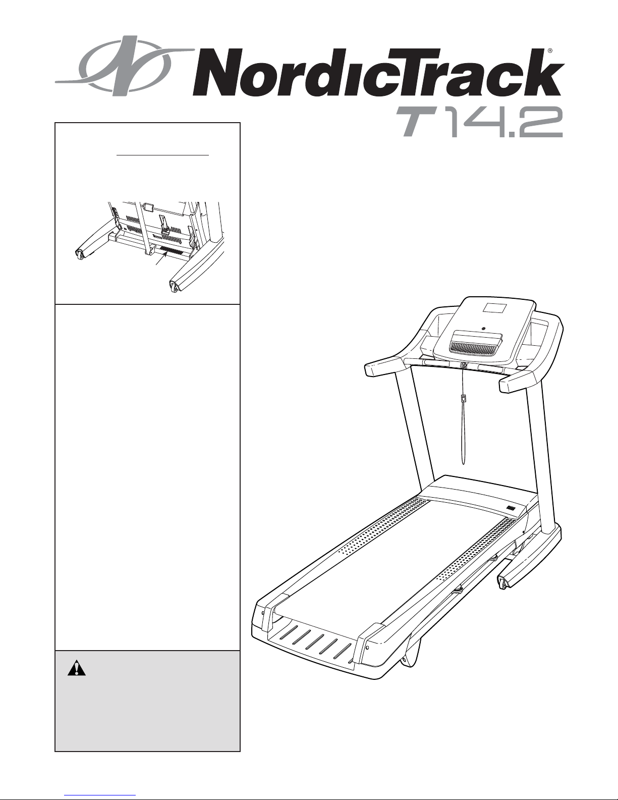
Serial No.
Write the serial number in the space
above for reference.
Serial Number
Decal
QUESTIONS?
If you have questions, or if there are
missing parts, please contact us:
UNITED KINGDOM
Call: 08457 089 009
From Ireland: 053 92 36102
Website: www.iconsupport.eu
E-mail: csuk@iconeurope.com
Write:
ICON Health & Fitness, Ltd.
c/o HI Group PLC
Express Way
CASTLEFORD
WF10 5QJ
UNITED KINGDOM
USER’S MANUAL
AUSTRALIA
Call: 1800 993 770
E-mail: australiacc@iconfitness.com
Write:
ICON Health & Fitness
PO Box 635
WINSTON HILLS NSW 2153
AUSTRALIA
CAUTION
Read all precautions and instructions in this manual before using
this equipment. Save this manual
for future reference.
www.iconeurope.com
256836
TABLE OF CONTENTS
WARNING DECAL PLACEMENT . . . . . . . . . . . . . . . . . . . . . . . . . . . . . . . . . . . . . . . . . . . . . . . . . . . . . . . . . . . . . . .2
IMPORTANT PRECAUTIONS ..................................................................3
BEFORE YOU BEGIN. . . . . . . . . . . . . . . . . . . . . . . . . . . . . . . . . . . . . . . . . . . . . . . . . . . . . . . . . . . . . . . . . . . . . . . .5
PART IDENTIFICATION CHART. . . . . . . . . . . . . . . . . . . . . . . . . . . . . . . . . . . . . . . . . . . . . . . . . . . . . . . . . . . . . . . .6
ASSEMBLY . . . . . . . . . . . . . . . . . . . . . . . . . . . . . . . . . . . . . . . . . . . . . . . . . . . . . . . . . . . . . . . . . . . . . . . . . . . . . . . .7
THE CHEST HEART RATE MONITOR. . . . . . . . . . . . . . . . . . . . . . . . . . . . . . . . . . . . . . . . . . . . . . . . . . . . . . . . . .15
OPERATION AND ADJUSTMENT .............................................................16
HOW TO FOLD AND MOVE THE TREADMILL . . . . . . . . . . . . . . . . . . . . . . . . . . . . . . . . . . . . . . . . . . . . . . . . . . .24
TROUBLESHOOTING ......................................................................25
EXERCISE GUIDELINES ....................................................................28
PART LIST. . . . . . . . . . . . . . . . . . . . . . . . . . . . . . . . . . . . . . . . . . . . . . . . . . . . . . . . . . . . . . . . . . . . . . . . . . . . . . . .30
EXPLODED DRAWING. . . . . . . . . . . . . . . . . . . . . . . . . . . . . . . . . . . . . . . . . . . . . . . . . . . . . . . . . . . . . . . . . . . . . .32
ORDERING REPLACEMENT PARTS. . . . . . . . . . . . . . . . . . . . . . . . . . . . . . . . . . . . . . . . . . . . . . . . . . . Back Cover
RECYCLING INFORMATION ......................................................... Back Cover
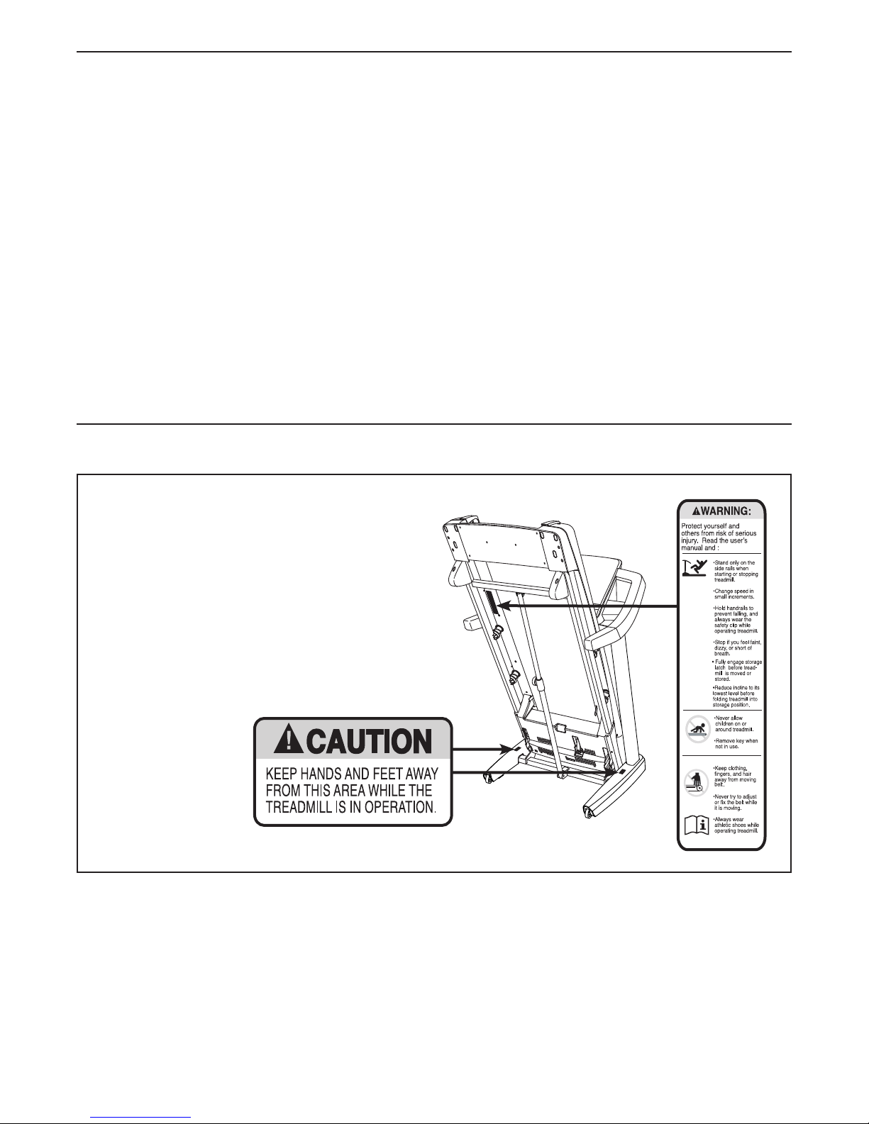
WARNING DECAL PLACEMENT
This drawing shows the locations of the warning decals. If a decal is missing or illegible,
call the telephone number on the front
cover of this manual and request a free
replacement decal. Apply the decal in the
location shown. Note: The decals may not be
shown at actual size.
NORDICTRACK is a registered trademark of ICON IP, Inc.
2

IMPORTANT PRECAUTIONS
WARNING: To reduce the risk of burns, fire, electric shock, or injury to persons, read
all important precautions and instructions in this manual and all warnings on your treadmill before
using your treadmill. ICON assumes no responsibility for personal injury or property damage sustained by or through the use of this product.
1. It is the responsibility of the owner to ensure
that all users of this treadmill are adequately
informed of all warnings and precautions.
2. Before beginning any exercise program,
consult your physician. This is especially
important for persons over age 35 or persons
with pre-existing health problems.
3. Use the treadmill only as described in this
manual.
4. The treadmill is intended for home use only.
Do not use the treadmill in any commercial,
rental, or institutional setting.
5. Keep the treadmill indoors, away from moisture and dust. Do not put the treadmill in a
garage or covered patio, or near water.
6. Place the treadmill on a level surface, with
at least 8 ft. (2.4 m) of clearance behind it
and 2 ft. (0.6 m) on each side. Do not place
the treadmill on any surface that blocks air
openings. To protect the floor or carpet from
damage, place a mat under the treadmill.
7. Do not operate the treadmill where aerosol
products are used or where oxygen is being
administered.
8. Keep children under age 12 and pets away
from the treadmill at all times.
12. When connecting the power cord (see page
16), plug the power cord into an earthed
circuit. No other appliance should be on the
same circuit. When replacing the fuse in the
power cord adapter, insert an ASTA-approved
BS1362, 13-amp fuse into the fuse carrier.
13. If an extension cord is needed, use only a
3-conductor, 14-gauge (1 mm2) cord that is
no longer than 5 ft. (1.5 m).
14. Keep the power cord away from heated
surfaces.
15. Never move the walking belt while the power
is turned off. Do not operate the treadmill
if the power cord or plug is damaged, or if
the treadmill is not working properly. (See
TROUBLESHOOTING on page 25 if the treadmill is not working properly.)
16. Read, understand, and test the emergency
stop procedure before using the treadmill
(see HOW TO TURN ON THE POWER on
page 18).
17. Never start the treadmill while you are standing on the walking belt. Always hold the
handrails while using the treadmill.
18. The treadmill is capable of high speeds.
Adjust the speed in small increments to
avoid sudden jumps in speed.
9. The treadmill should be used only by persons weighing 350 lbs. (159 kg) or less.
10. Never allow more than one person on the
treadmill at a time.
11. Wear appropriate exercise clothes while
using the treadmill. Do not wear loose
clothes that could become caught in the
treadmill. Athletic support clothes are recommended for both men and women. Always
wear athletic shoes. Never use the treadmill
with bare feet, wearing only stockings, or in
sandals.
19. The heart rate monitor is not a medical
device. Various factors, including the user’s
movement, may affect the accuracy of heart
rate readings. The heart rate monitor is
intended only as an exercise aid in determining heart rate trends in general.
20. Never leave the treadmill unattended while
it is running. Always remove the key, press
the power switch into the off position (see
the drawing on page 5 for the location of the
power switch), and unplug the power cord
when the treadmill is not in use.
3

21. Do not attempt to raise, lower, or move the
treadmill until it is properly assembled. (See
ASSEMBLY on page 7, and HOW TO FOLD
AND MOVE THE TREADMILL on page 24.)
You must be able to safely lift 45 lbs. (20 kg)
to raise, lower, or move the treadmill.
22. When folding or moving the treadmill, make
sure that the storage latch is holding the
frame securely in the storage position.
25. DANGER: Always unplug the power
cord immediately after use, before cleaning the treadmill, and before performing the
maintenance and adjustment procedures
described in this manual. Never remove the
motor hood unless instructed to do so by an
authorized service representative. Servicing
other than the procedures in this manual
should be performed by an authorized service representative only.
23. Never insert any object into any opening on
the treadmill.
24. Inspect and properly tighten all parts of the
treadmill regularly.
SAVE THESE INSTRUCTIONS
26. Over exercising may result in serious injury
or death. If you feel faint or if you experience
pain while exercising, stop immediately and
cool down.
4

BEFORE YOU BEGIN
Thank you for selecting the new NORDICTRACK®
T14.2 treadmill. The T14.2 treadmill provides an
impressive selection of features designed to make your
workouts at home more effective and enjoyable.
For your benefit, read this manual carefully before
you use the treadmill. If you have questions after
reading this manual, please see the front cover of this
Length: 6 ft. 8 in. (203 cm)
Width: 3 ft. 2 in. (97 cm)
Weight: 225 lbs. (102 kg)
Handrail
manual. To help us assist you, note the product model
number and serial number before contacting us. The
model number and the location of the serial number
decal are shown on the front cover of this manual.
Before reading further, please familiarize yourself with
the parts that are labeled in the drawing below.
Console
Accessory Tray
Heart Rate Monitor
Key/Clip
Walking Belt
Foot Rail
Idler Roller
Adjustment Screws
Motor Hood
Power Switch
Wheel
Platform Cushion
5
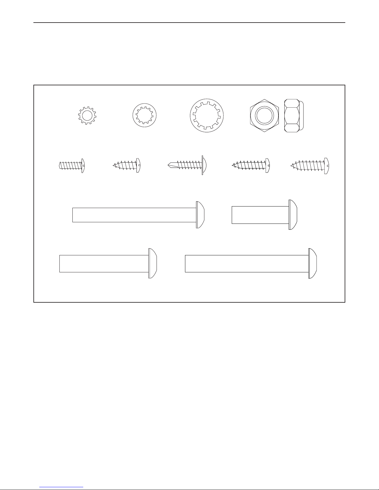
PART IDENTIFICATION CHART
Use the drawings below to identify small parts used for assembly. The number in parentheses below each drawing is the key number of the part, from the PART LIST near the end of this manual. The number following the key
number is the quantity used for assembly. Note: If a part is not in the hardware kit, check to see if it is preat-
tached. Extra parts may be included.
#10 Star
Washer (5)–4
#8 x 1/2" Ground
Screw (6)–1
3/8" x 2" Bolt (2)–2
5/16" Star
Washer (8)–4
#8 x 1/2"
Screw (1)–14
5/16" x 2 3/4" Screw (12)–4
#8 x 3/4" Tek
Screw (13)–8
3/8" Star
Washer (10)–8
3/8" x 2 3/4" Screw (22)–4
3/8" Nut (9)–2
#8 x
3/4"
Screw (14)–4
3/8" x 1 1/4"
Screw (3)–4
#10 x 3/4"
Screw (4)–4
6
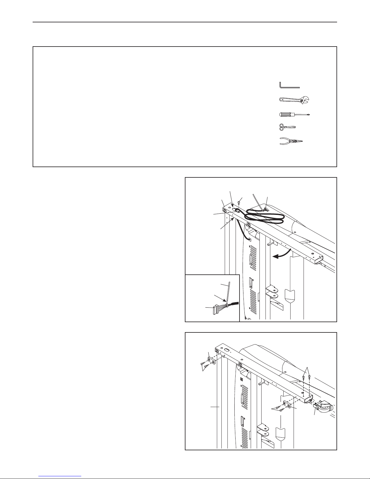
ASSEMBLY
• Assembly requires two persons.
• Place all parts in a cleared area and remove the
packing materials. Do not dispose of the packing
materialsuntilyounishallassemblysteps.
• After shipping, there may be an oily substance
on the exterior of the treadmill. This is normal. If
there is an oily substance on the treadmill, wipe
it off with a soft cloth and a mild, non-abrasive
cleaner.
• Left parts are marked “L” or “Left and right parts
are marked “R” or “Right.”
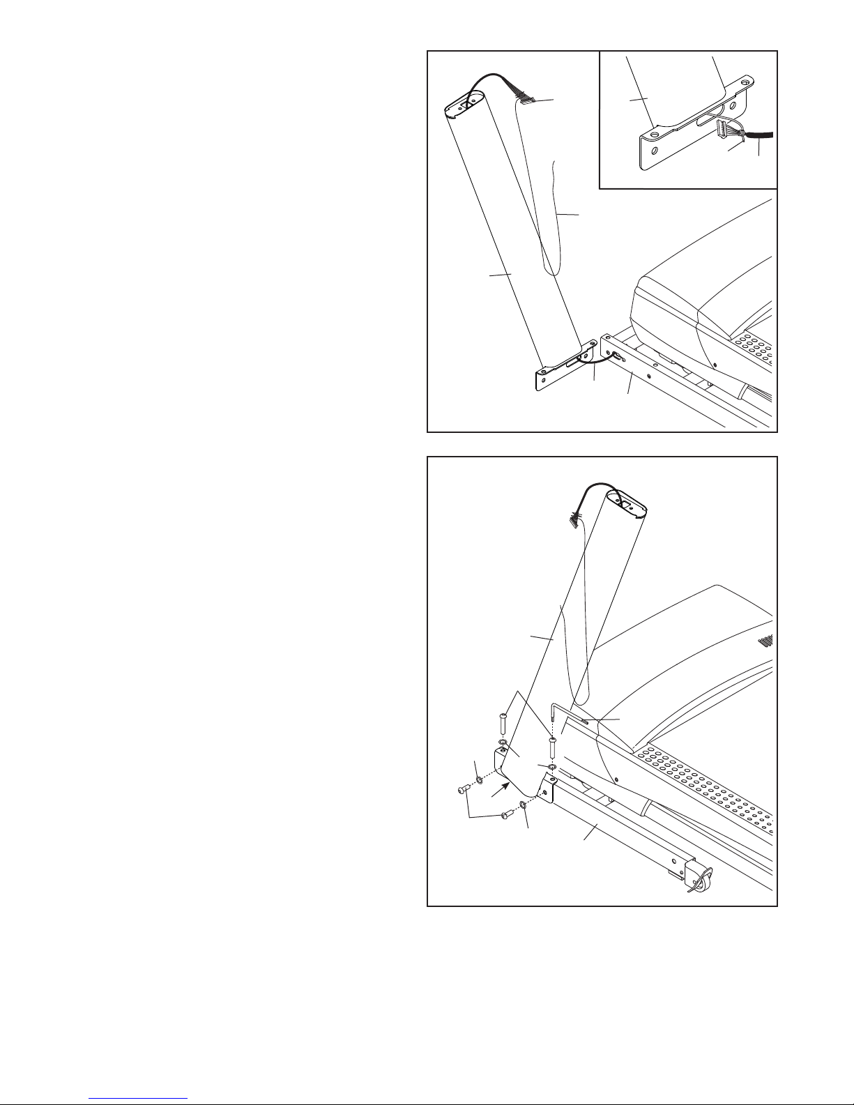
1. Make sure that the power cord is unplugged.
With the help of a second person, tip the tread-
mill onto its right side.
Pull the Upright Wire (91) and the base ground
wire (A) through the indicated hole in the
Base (29).
• To identify small parts, see page 6.
• Assembly requires the following tools:
the included hex keys
one adjustable wrench
one Phillips screwdriver
scissors
needlenose pliers
To avoid damaging parts, do not use power tools.
1
Hole
29
A
90
6
91
Attach the base ground wire (A) to the Base (29)
with a #8 x 1/2" Ground Screw (6).
Make sure that the Grommet (90) is pressed into
the square hole in the Base.
See the inset drawing. Cut the plastic tie near
the Upright Wire (91). Be careful not to dam-
age the Upright Wire.
2. Attach the Left Wheel Cap (113) to the Base (29)
with two #8 x 3/4" Screws (14).
Attach four Base Pads (37) to the Base (29) with
eight #8 x 3/4" Tek Screws (13) (only one side is
shown). Do not overtighten the Screws.
With the help of a second person, tip the tread-
mill so that the Base (29) is flat on the floor.
Attach the Right Wheel Cap (not shown) as
described above.
Tie
Cut
91
2
37
14
13
29
13
37
113
7
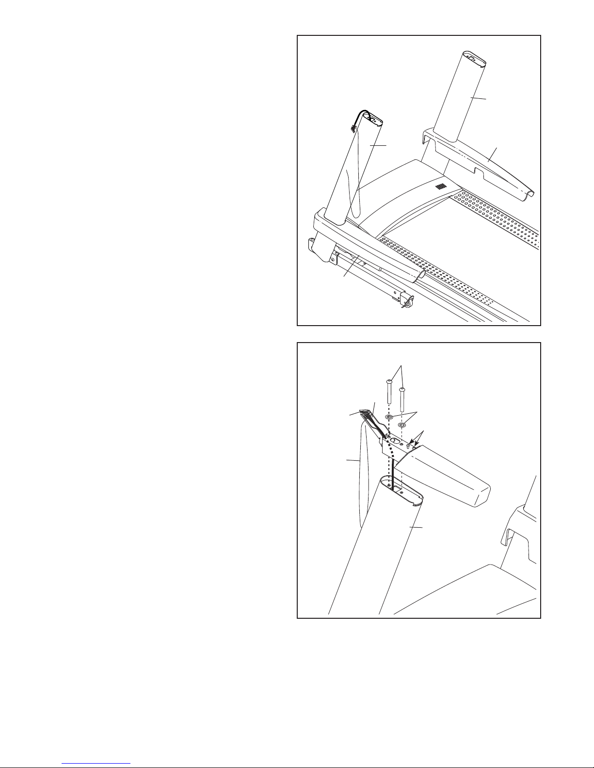
3. Identify the Left Upright (84). Have a second
person hold the Left Upright near the Base (29).
3
See the inset drawing. Tie the wire tie in the
Left Upright (84) securely around the end of the
Upright Wire (91). Then, pull the other end of the
wire tie until the Upright Wire is routed through
the Left Upright.
4. Hold the Left Upright (84) against the Base (29).
Be careful not to pinch the wires. If necessary, position the base ground wire (A) in the
hole in the side of the Left Upright. Insert two
3/8" x 2 3/4" Screws (22) with two 3/8” Star
Washers (10) and two 3/8" x 1 1/4" Screws (3)
with two 3/8" Star Washers (10) into the Left
Upright.
91
84
4
Wire
Tie
91
84
29
Wire
Tie
91
Partially tighten the 3/8" x 2 3/4" Screws (22)
and the 3/8" x 1 1/4" Screws (3) until the heads
of the Screws touch the Left Upright (84); do not
fully tighten the Screws yet. Note: It may be
helpful to use the short hex key (B) on the Screw
shown.
Attach the Right Upright (not shown) in the
same way. Note: There are no wires on the right
side.
3
10
84
22
B
10
A
10
29
8
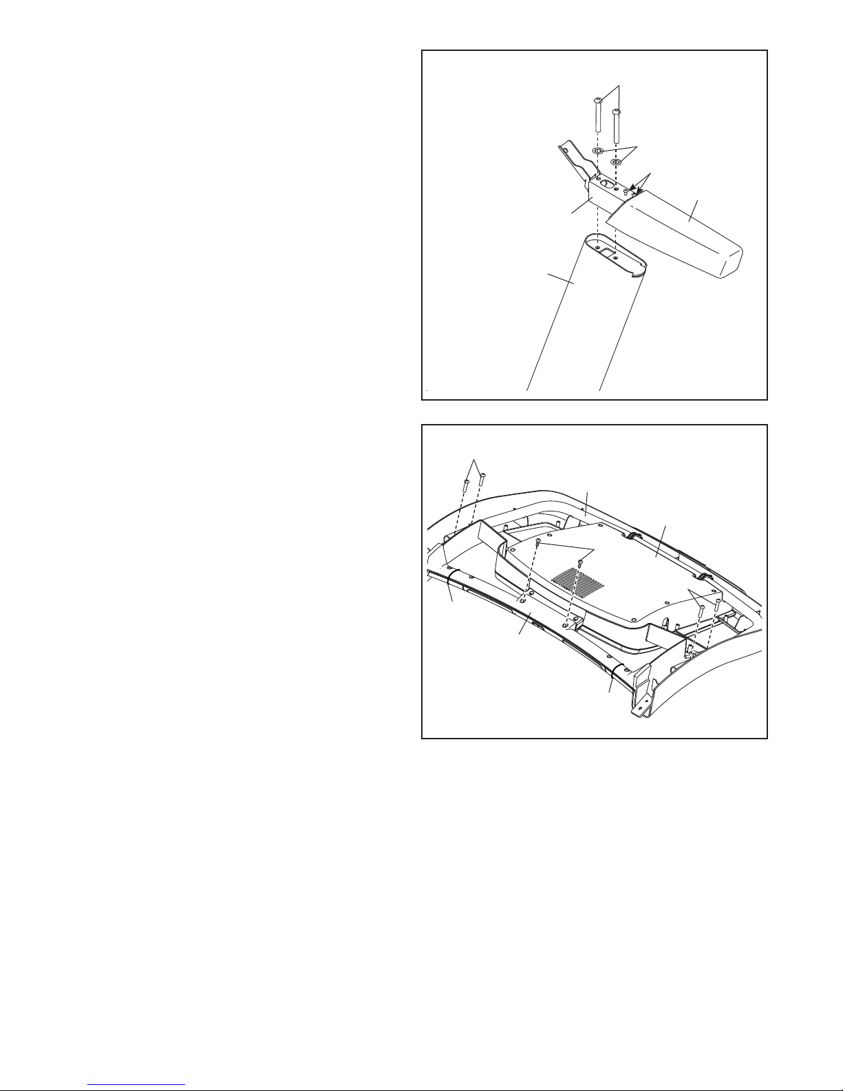
5. Identify the Left and Right Base Covers (88, 89).
Slide the Left Base Cover onto the Left Upright
(84). Slide the Right Base Cover onto the Right
Upright (85). Do not press the Base Covers
into place yet.
5
85
6. Identify the left Handrail (79). If there is a wire in
the left Handrail, remove and discard it.
Hold the left Handrail (79) near the Left Upright
(84). Insert the wire tie on the Upright Wire (91)
into the bottom and out of the end of the left
Handrail as shown. Then, pull the Upright Wire
through the Left Handrail.
84
88
6
91
12
79
8
C
89
Attach the left Handrail (79) to the Left Upright
(84) with two 5/16" x 2 3/4" Screws (12) and two
5/16" Star Washers (8). Make sure not to pinch
the Upright Wire (91). Do not tighten the
Screws yet.
Remove and discard the two indicated screws
(C) from the left Handrail (79).
Wire
Tie
84
9
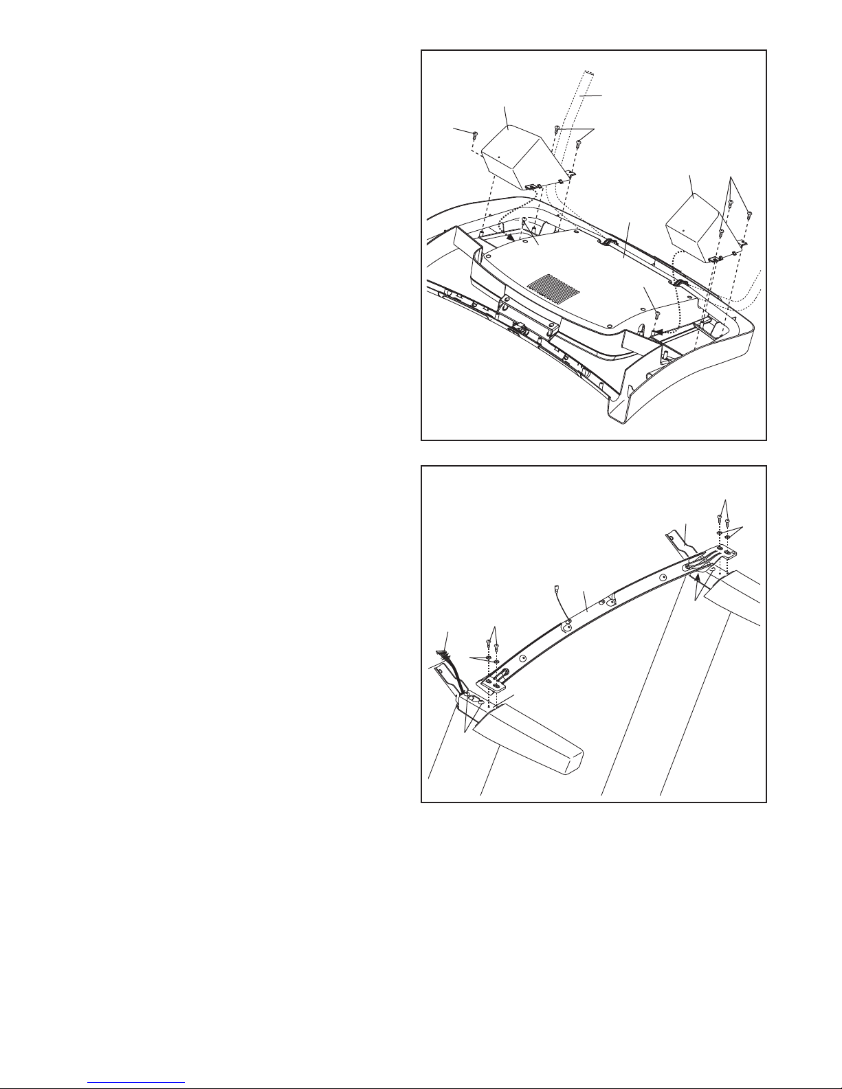
7. Attach the right Handrail (79) to the Right
Upright (85) with two 5/16" x 2 3/4" Screws (12)
and two 5/16" Star Washers (8). Do not tighten
the Screws yet.
7
12
Remove and discard the two indicated screws
(C) from the right Handrail (79).
8. Set the Console Base (98) face down on a soft
surface to avoid scratching the Console Base.
Remove the two screws (D) and two ties from
the Pulse Crossbar (81). Remove the Pulse
Crossbar and discard the screws.
8
C
83
79
85
4
8
11
101
98
Remove the four 5/16" x 5/8" Screws (11) from
the Console Frame (101). The Screws will be
used in a later step.
D
11
Tie
81
Tie
10
9. Identify the Left and Right Trays (95, 96).
9
Attach the Left and Right Trays (95, 96) to the
Console Base (98) with eight #8 x 1/2" Screws
(1). Tip: It may be easier to start the two
inside Screws and then slide the Trays into
place before tightening the other six Screws.
Note: It may be necessary to rotate the Console
Frame (101) upward when attaching the Left and
Right Trays (95, 96).
10. IMPORTANT: To avoid damaging the Pulse
Crossbar (81), do not use power tools and do
not overtighten the #10 x 3/4" Screws (4).
Orient the Pulse Crossbar (81) as shown. Attach
the Pulse Crossbar to the Handrails (79) with
four #10 x 3/4" Screws (4) and four #10 Star
Washers (5). Start all four Screws, and then
tighten them.
Make sure that the Upright Wire (91) is not
pinched. Firmly tighten the four 5/16" x 2 3/4"
Screws (12).
10
1
91
81
1
101
98
95
1
79
1
4
5
12
96
1
4
5
79
12
11