

Page 1
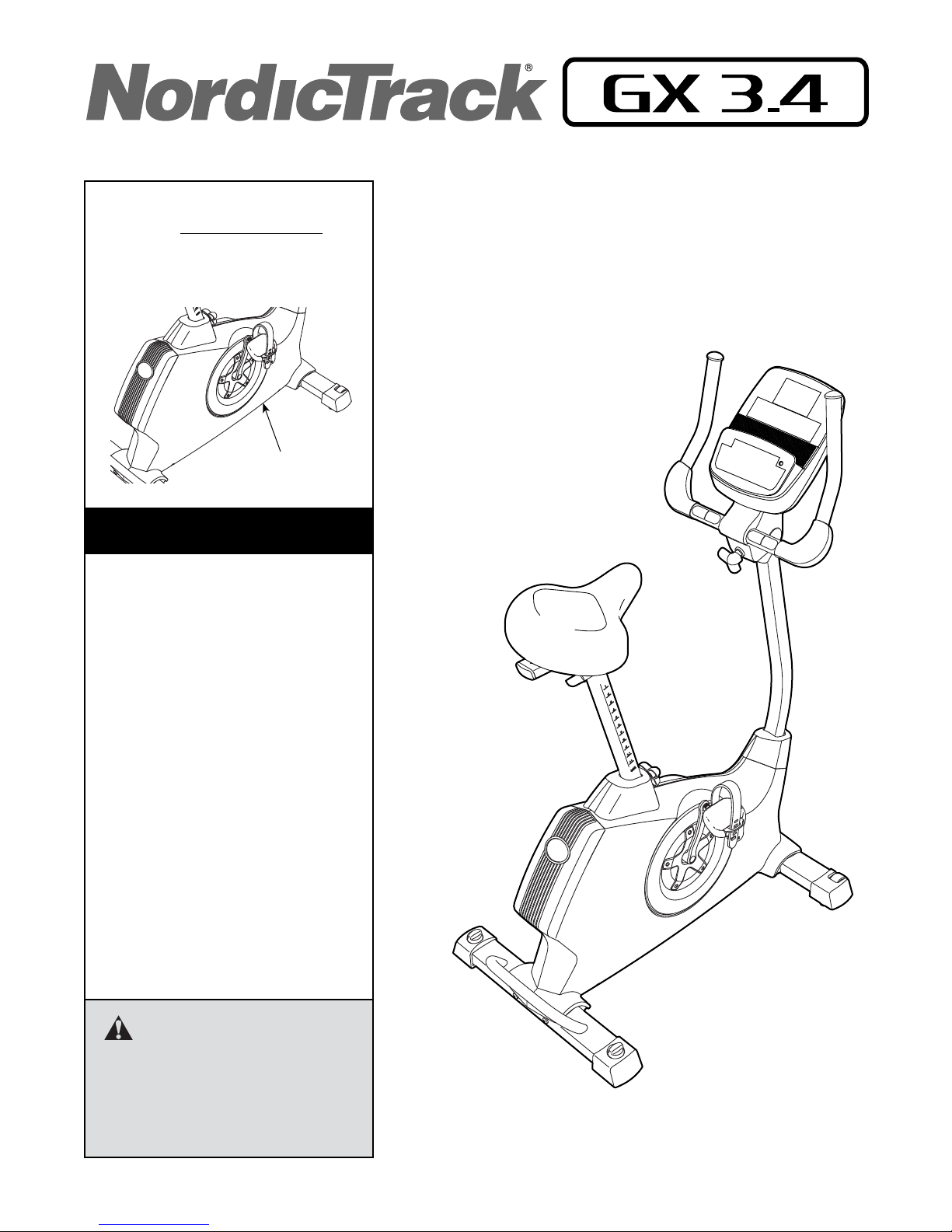
Model No. NTEVEX78612.0
Serial No.
Write the serial number in the space
above for reference.
Serial Number Decal
(under frame)
CUSTOMER SERVICE
UNITED KINGDOM
Call: 08457 089 009
From Ireland: 053 92 36102
Website: www.iconsupport.eu
E-mail: [email protected]
Write:
ICON Health & Fitness, Ltd.
c/o HI Group PLC
Express Way
CASTLEFORD
WF10 5QJ
UNITED KINGDOM
USER’S MANUAL
AUSTRALIA
Call: 1800 993 770
E-mail: [email protected]
Write:
ICON Health & Fitness
PO Box 635
WINSTON HILLS NSW 2153
AUSTRALIA
CAUTION
Read all precautions and instructions in this manual before using
this equipment. Keep this manual
for future reference.
www.iconeurope.com
Page 2
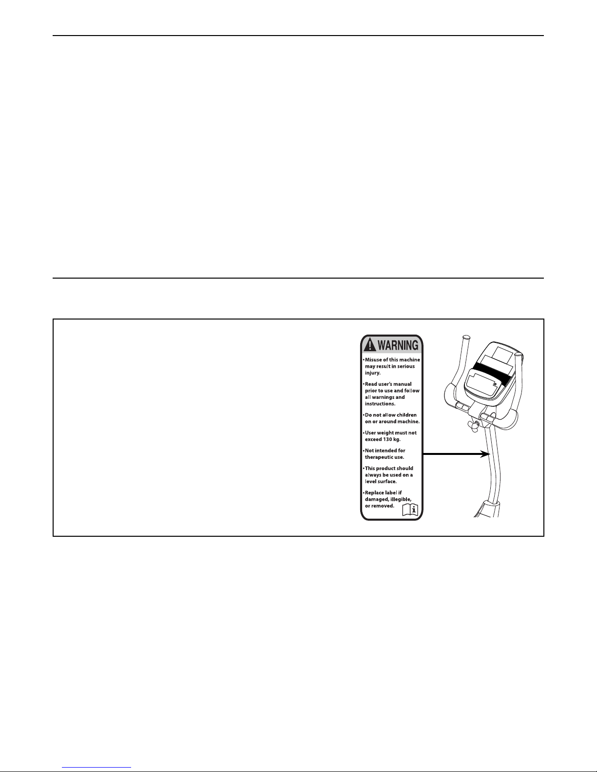
TABLE OF CONTENTS
WARNING DECAL PLACEMENT . . . . . . . . . . . . . . . . . . . . . . . . . . . . . . . . . . . . . . . . . . . . . . . . . . . . . . . . . . . . . . .2
IMPORTANT PRECAUTIONS ..................................................................3
BEFORE YOU BEGIN. . . . . . . . . . . . . . . . . . . . . . . . . . . . . . . . . . . . . . . . . . . . . . . . . . . . . . . . . . . . . . . . . . . . . . . .4
PART IDENTIFICATION CHART. . . . . . . . . . . . . . . . . . . . . . . . . . . . . . . . . . . . . . . . . . . . . . . . . . . . . . . . . . . . . . . .5
ASSEMBLY . . . . . . . . . . . . . . . . . . . . . . . . . . . . . . . . . . . . . . . . . . . . . . . . . . . . . . . . . . . . . . . . . . . . . . . . . . . . . . . .6
THE CHEST HEART RATE MONITOR. . . . . . . . . . . . . . . . . . . . . . . . . . . . . . . . . . . . . . . . . . . . . . . . . . . . . . . . . .12
HOW TO USE THE EXERCISE BIKE. . . . . . . . . . . . . . . . . . . . . . . . . . . . . . . . . . . . . . . . . . . . . . . . . . . . . . . . . . . 13
MAINTENANCE AND TROUBLESHOOTING .....................................................25
EXERCISE GUIDELINES ....................................................................27
PART LIST. . . . . . . . . . . . . . . . . . . . . . . . . . . . . . . . . . . . . . . . . . . . . . . . . . . . . . . . . . . . . . . . . . . . . . . . . . . . . . . .29
EXPLODED DRAWING. . . . . . . . . . . . . . . . . . . . . . . . . . . . . . . . . . . . . . . . . . . . . . . . . . . . . . . . . . . . . . . . . . . . . .31
ORDERING REPLACEMENT PARTS .................................................. Back Cover
RECYCLING INFORMATION ......................................................... Back Cover
WARNING DECAL PLACEMENT
This drawing shows the location(s) of the warning decal(s).
If a decal is missing or illegible, see the front cover
of this manual and request a free replacement decal.
Apply the decal in the location shown. Note: The
decal(s) may not be shown at actual size.
NORDICTRACK is a registered trademark of ICON IP, Inc.
2
Page 3
IMPORTANT PRECAUTIONS
WARNING: To reduce the risk of serious injury, read all important precautions and
instructions in this manual and all warnings on your exercise bike before using your exercise bike.
ICON assumes no responsibility for personal injury or property damage sustained by or through the
use of this product.
1. It is the responsibility of the owner to ensure
that all users of the exercise bike are adequately informed of all precautions.
2. Before beginning any exercise program,
consult your physician. This is especially
important for persons over age 35 or persons with pre-existing health problems.
3. Use the exercise bike only as described in
this manual.
4. The exercise bike is intended for home use
only. Do not use the exercise bike in a commercial, rental, or institutional setting.
5. Keep the exercise bike indoors, away from
moisture and dust. Do not put the exercise
bike in a garage or covered patio, or near
water.
6. Place the exercise bike on a level surface
with at least 2 ft. (0.6 m) of clearance around
the exercise bike. To protect the floor or
carpet from damage, place a mat under the
exercise bike.
7. Inspect and properly tighten all parts regularly. Replace any worn parts immediately.
8. Keep children under age 12 and pets away
from the exercise bike at all times.
9. Wear appropriate clothes while exercising;
do not wear loose clothes that could become
caught on the exercise bike. Always wear
athletic shoes for foot protection.
10. The exercise bike should not be used by
persons weighing more than 286 lbs.
(130 kg).
11. Be careful when mounting and dismounting
the exercise bike.
12. The heart rate monitor is not a medical
device. Various factors, including the user’s
movement, may affect the accuracy of heart
rate readings. The heart rate monitor is
intended only as an exercise aid in determining heart rate trends in general.
13. Always keep your back straight while using
the exercise bike; do not arch your back.
14. Over exercising may result in serious injury
or death. If you feel faint or if you experience
pain while exercising, stop immediately and
cool down.
3
Page 4
BEFORE YOU BEGIN
Thank you for selecting the revolutionary
NORDICTRACK® GX 3.4 exercise bike. Cycling is an
effective exercise for increasing cardiovascular fitness,
building endurance, and toning the body. The GX 3.4
exercise bike provides an impressive selection of features designed to make your workouts at home more
effective and enjoyable.
For your benefit, read this manual carefully before
you use the exercise bike. If you have questions after
Length: 3 ft. 5 in. (104 cm)
Width: 1 ft. 11 in. (58 cm)
Heart Rate Monitor
reading this manual, please see the front cover of this
manual. To help us assist you, note the product model
number and serial number before contacting us. The
model number and the location of the serial number
decal are shown on the front cover of this manual.
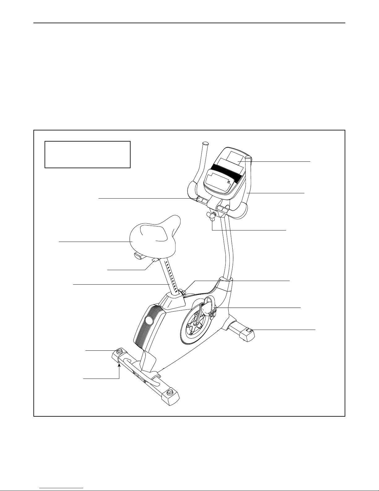
Before reading further, please familiarize yourself with
the parts that are labeled in the drawing below.
Console
Handlebar
Seat
Seat Adjustment Knob
Seat Post
Leveling Knob
Leveling Foot
Adjustment Knob
Seat Post Knob
Pedal/Strap
Wheel
4
Page 5
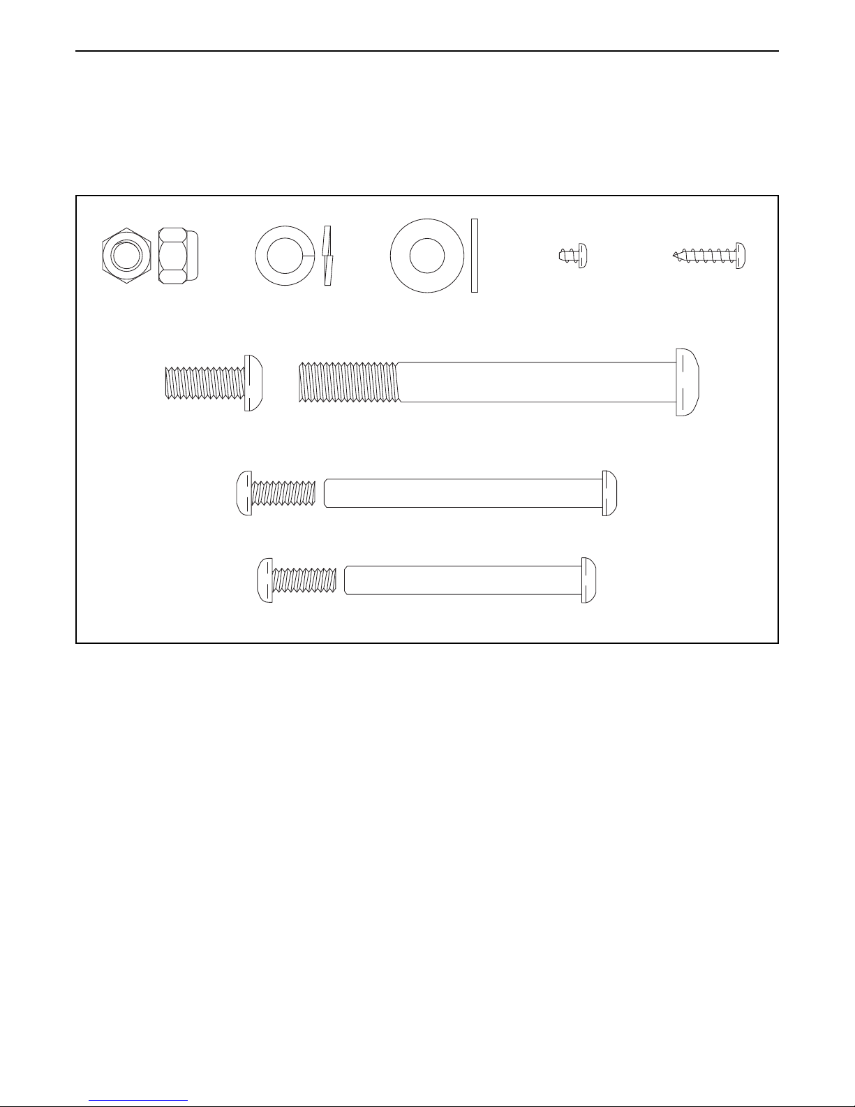
PART IDENTIFICATION CHART
Use the drawings below to identify small parts used in assembly. The number in parentheses by each drawing is
the key number of the part, from the PART LIST near the end of this manual. The number following the key number is the quantity needed for assembly. Note: If a part is not in the hardware kit, check to see if it has been
preattached.
M8 Locknut
(72)–4
M8 x 20mm
Screw (74)–4
M8 Split
Washer (75)–8
M8 Washer
(43)–2
M10 x 95mm
Screw (76)–4
M6 x 70mm Bolt Set (50)–1
M6 x 60mm Bolt Set (51)–1
M4 x 5mm
Bright Screw
(91)–1
M4 x 16mm
Screw (90)–8
5
Page 6
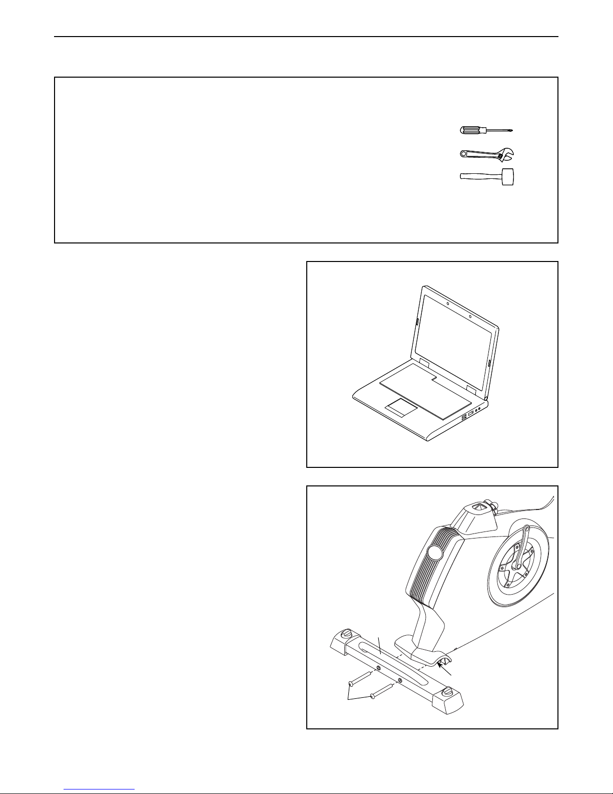
ASSEMBLY
• Assembly requires two persons.
• Place all parts in a cleared area and remove the
packing materials. Do not dispose of the packing
materials until you complete all assembly steps.
• Left parts are marked “L” or “Left” and right parts
are marked “R” or “Right.”
• To identify small parts, see page 5.
1. Go to www.iconsupport.eu on your computer
and register your product.
• activatesyourwarranty
• savesyoutimeifyoueverneedtocontact
Customer Service
• allowsustonotifyyouofupgradesandoffers
Note: If you do not have Internet access, call
Customer Service (see the front cover of this
manual) and register your product.
• In addition to the included tool(s), assembly
requires the following tools:
one Phillips screwdriver
one adjustable wrench
one rubber mallet
Assembly may be easier if you have a set of
wrenches. To avoid damaging parts, do not use
power tools.
1
2. Attach the Rear Stabilizer (3) to the Frame (1)
with two M10 x 95mm Screws (76).
2
3
1
76
6
Page 7
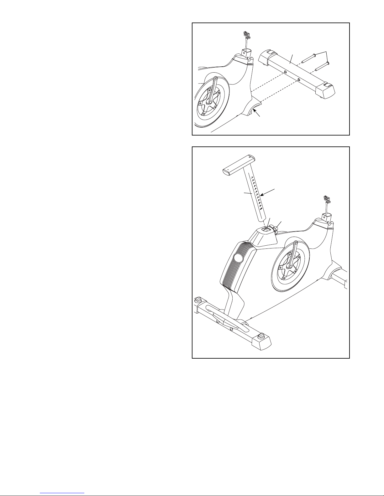
3. Attach the Front Stabilizer (2) to the Frame (1)
with two M10 x 95mm Screws (76).
3
4. Loosen the Adjustment Knob (27) in the Frame
(1) a few turns.
Orient the Seat Post (6) as shown. Then, pull
the Adjustment Knob (27) outward and insert the
Seat Post into the Frame (1).
Slide the Seat Post (6) upward or downward to
the desired position, and release the Adjustment
Knob (27).
2
1
4
Adjustment
1
Holes
27
6
76
Move the Seat Post (6) upward or downward
slightly to make sure that the Adjustment
Knob (27) is engaged in one of the adjustment holes in the Seat Post. Then, tighten the
Adjustment Knob.
7
Page 8
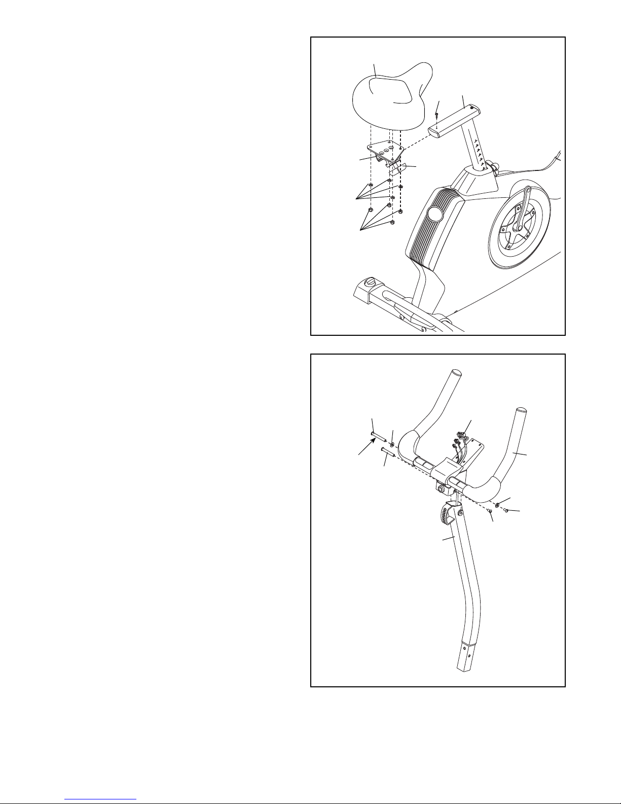
5. Orient the Seat (23) and the Seat Carriage (24)
as shown.
Attach the Seat (23) to the Seat Carriage (24)
with four M8 Locknuts (72) and four M8 Split
Washers (75).
Slide the Seat Carriage (24) onto the Seat
Post (6). Then, slide the Seat Carriage all the
way forward and tighten the Seat Adjustment
Knob (26).
Attach an M4 x 5mm Bright Screw (91) to the
rear of the Seat Post (6).
5
23
6
91
24
75
72
26
6. Using a plastic bag to keep your fingers clean,
apply some of the included grease to an M6 x
70mm Bolt Set (50).
Orient the Handlebar (5) and the Upright (4) as
shown.
While a second person holds the Handlebar (5)
near the Upright (4), insert the Upper Wire (59)
upward through the Handlebar.
Tip: Avoid pinching the Upper Wire (59).
Attach the Handlebar (5) to the Upright (4)
with the M6 x 70mm Bolt Set (50) and two M8
Washers (43).
Then, attach an M6 x 60mm Bolt Set (51)
through the lower bracket on the Handlebar (5).
6
50
43
Grease
51
Avoid pinching the
Upper Wire (59)
59
5
43
50
51
4
8
Page 9
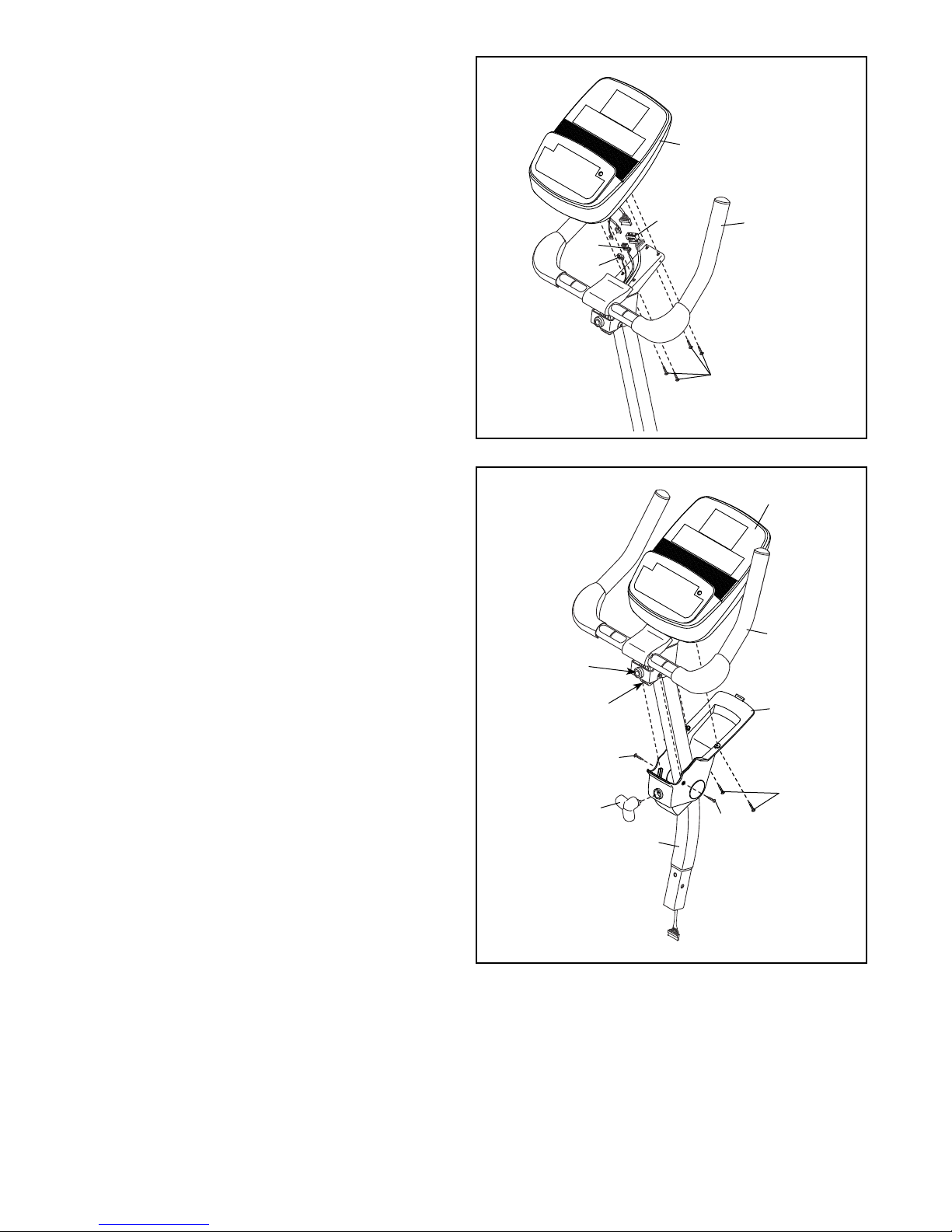
7. While another person holds the Console (13)
near the Handlebar (5), connect the wires on the
Console to the Upper Wire (59), the Pulse Wire
(61), and the Receiver Wire (16).
Insert the excess wire into the Handlebar (5).
Tip: Avoid pinching the wires. Attach the
Console (13) to the Handlebar (5) with four M4 x
16mm Screws (90).
7
13
Avoid pinching
the wires
59
61
16
5
90
8. Orient the Upright (4) assembly and the Pivot
Cover (12) as shown.
Slide the Pivot Cover (12) upward to the
Handlebar (5). Tip: Bend and flex the Pivot
Cover slightly to slide it over the Handlebar.
Attach the Pivot Cover (12) to the Handlebar
(5) and the Console (13) with four M4 x 16mm
Screws (90).
Pivot the Handlebar (5) until the hole in the
Handlebar is aligned with an adjustment hole in
the Upright (4).
Tighten an Adjustment Knob (27) into the
Handlebar (5) and an adjustment hole in the
Upright (4). Make sure that the Adjustment
Knob is engaged in one of the adjustment
holes.
8
Hole
Adjustment
Holes
27
13
5
12
90
90
90
4
9
Page 10
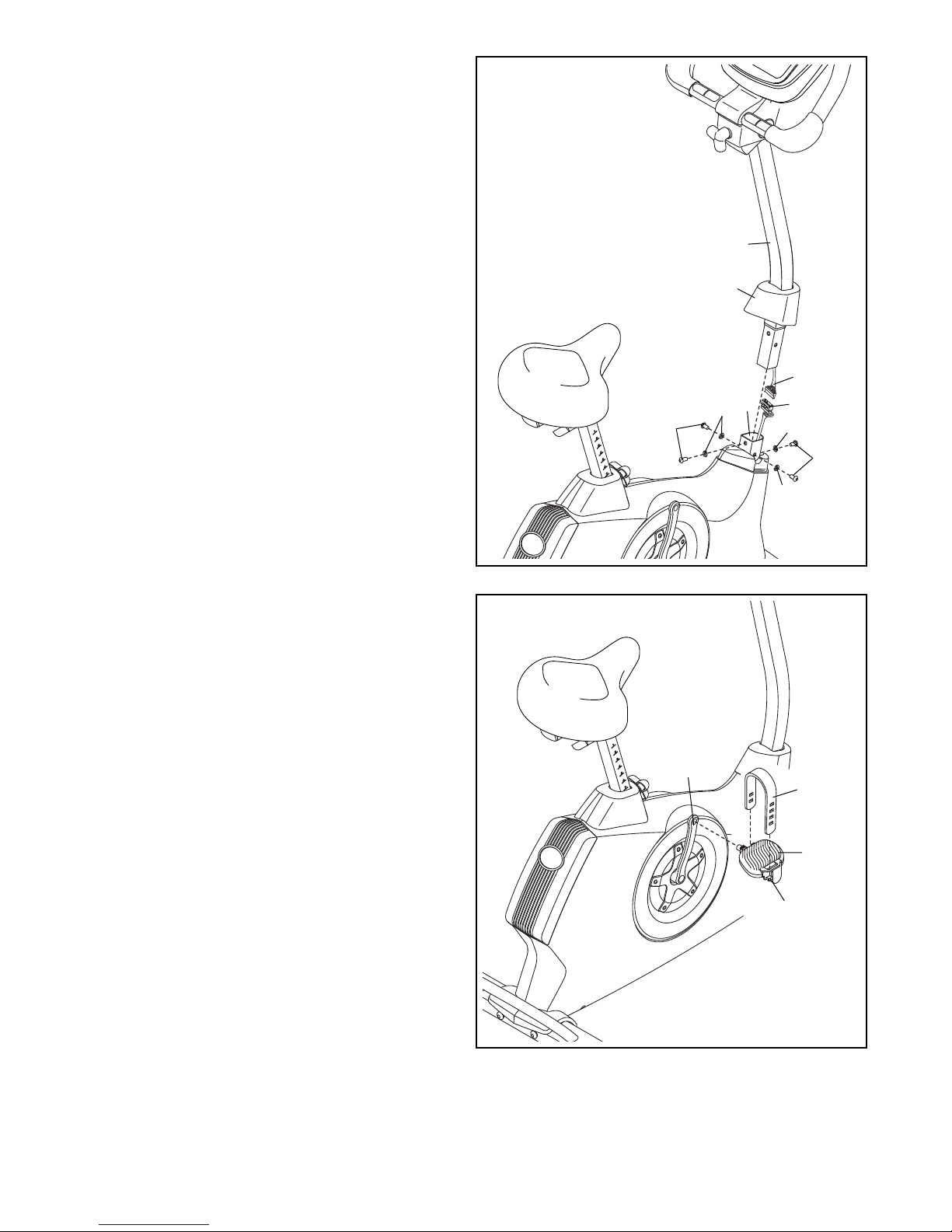
9. Slide the Front Shield Cover (7) upward onto the
Upright (4).
While another person holds the Upright (4) near
the Frame (1), connect the Upper Wire (59) to
the Lower Wire (58).
Insert the Upright (4) into the Frame (1).
Tip: Avoid pinching the wires. Attach the
Upright (4) with four M8 x 20mm Screws (74)
and four M8 Split Washers (75).
Slide the Front Shield Cover (7) downward to the
Frame (1) and press it into place.
9
Avoid pinching
the wires
4
7
59
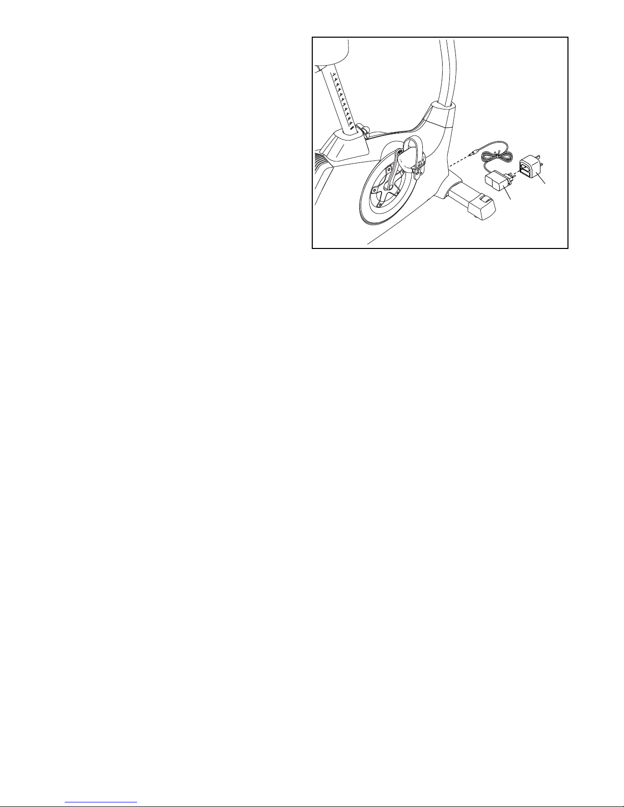
10. Identify the Right Pedal (21).
Using an adjustable wrench, firmly tighten the
Right Pedal (21) clockwise into the Right Crank
Arm (19).
Tighten the Left Pedal (not shown) counter-
clockwise into the Left Crank Arm (not shown).
Adjust the strap on the Right Pedal (21) to the
desired position, and press the ends of the
straps onto the tabs on the Right Pedal.
Adjust the strap on the Left Pedal (not
shown) in the same way.
10
74
19
75
1
58
75
74
75
Strap
21
Tab
10
Page 11
11. Plug the Power Adapter (67) into the receptacle
on the frame of the exercise bike.
If necessary, plug the Power Adapter (67) into
the Plug Adapter (B).
Note: To plug the Power Adapter (67) into an
outlet, see HOW TO PLUG IN THE POWER
ADAPTER on page 13.
12. After the exercise bike is assembled, inspect it to make sure that it is assembled correctly and that it
functions properly. Make sure that all parts are properly tightened before you use the exercise bike.
Note: Some hardware may be left over after assembly is completed. Place a mat under the exercise bike
to protect the floor or carpet.
11
B
67
11
Page 12
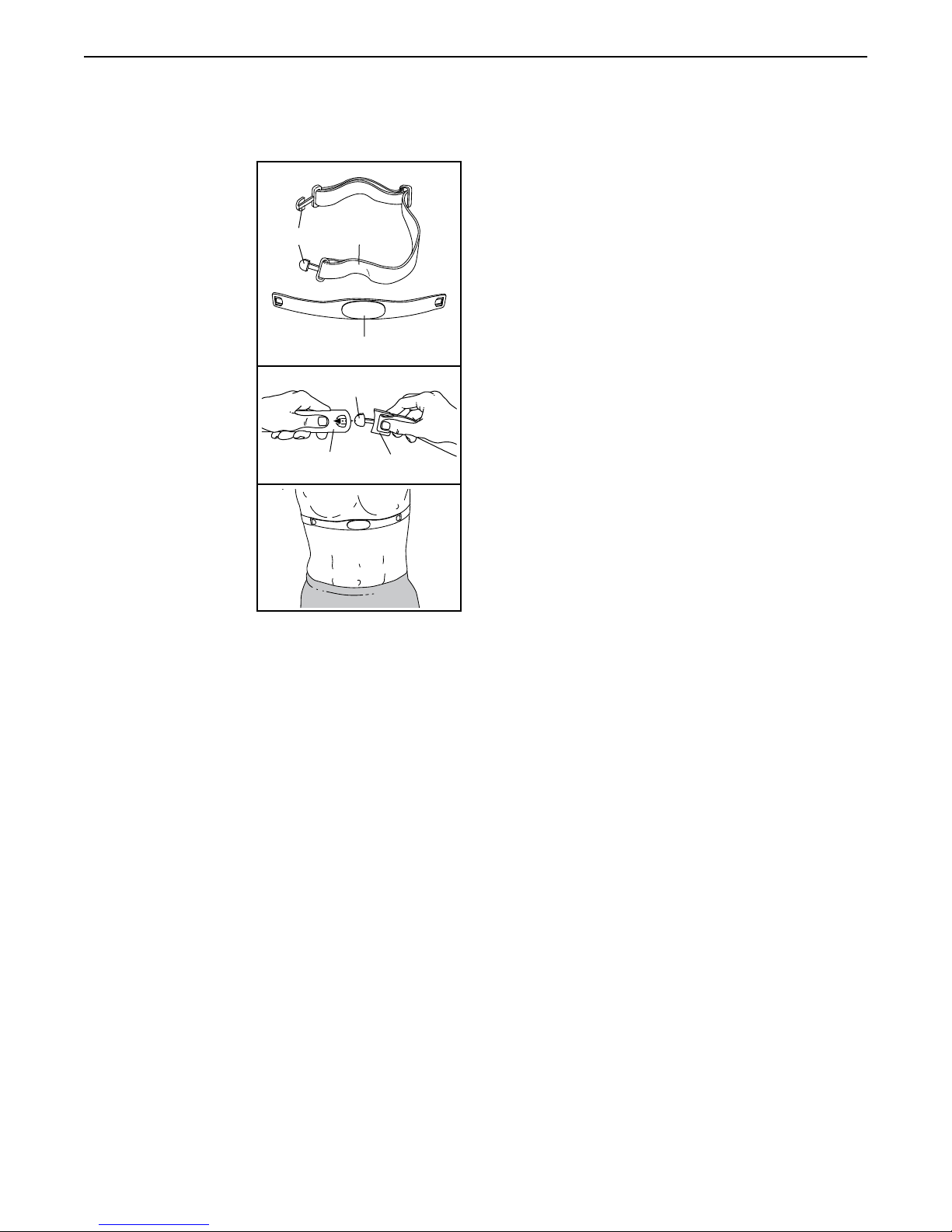
THE CHEST HEART RATE MONITOR
HOW TO PUT ON THE HEART RATE MONITOR
The heart rate
monitor consists of
a chest strap and a
sensor. Insert the
tab on one end of
the chest strap into
the hole in one end
of the sensor as
shown. Then, press
the end of the sensor under the buckle
on the chest strap.
The tab should be
flush with the front of
the sensor.
The heart rate monitor must be worn
under your clothes,
tight against your
skin. Wrap the heart
rate monitor around
your chest in the
location shown.
Make sure that
the logo is rightside-up. Then, attach the other end of the chest strap
to the sensor. Adjust the length of the chest strap, if
necessary.
Pull the sensor away from your body a few inches and
locate the two electrode areas, which are covered by
shallow ridges. Using saline solution such as saliva or
contact lens solution, wet the electrode areas. Then,
return the sensor to a position against your chest.
CARE AND MAINTENANCE
• Thoroughly dry the sensor with a soft towel after
each use. Moisture may keep the sensor activated,
shortening the life of the battery.
• Store the heart rate monitor in a warm, dry place. Do
not store the heart rate monitor in a plastic bag or
other container that may trap moisture.
Tabs
Chest
Sensor
Strap
Sensor
Tab
Buckle
• Do not expose the heart rate monitor to direct sunlight for extended periods of time; do not expose it to
temperatures above 122° F (50° C) or below 14° F
(-10° C).
• Do not excessively bend or stretch the sensor when
using or storing the heart rate monitor.
• To clean the sensor, use a damp cloth and a small
amount of mild soap. Then, wipe the sensor with a
damp cloth and thoroughly dry it with a soft towel.
Never use alcohol, abrasives, or chemicals to clean
the sensor. Hand wash and air dry the chest strap.
TROUBLESHOOTING
If the heart rate monitor does not function properly, try
the steps below.
• Make sure that you are wearing the heart rate monitor as described at the left. If the heart rate monitor
does not function when positioned as described,
move it slightly lower or higher on your chest.
• If heart rate readings are not displayed until you
begin perspiring, rewet the electrode areas.
• For the console to display heart rate readings, you
must be within arm’s length of the console.
• If there is a battery cover on the back of the sensor,
replace the battery with a new battery of the same
type.
• The heart rate monitor is designed to work with
people who have normal heart rhythms. Heart rate
reading problems may be caused by medical conditions such as premature ventricular contractions
(pvcs), tachycardia bursts, and arrhythmia.
• The operation of the heart rate monitor can be
affected by magnetic interference from high power
lines or other sources. If you suspect that magnetic
interference is causing a problem, try relocating the
fitness equipment.
12
Page 13
HOW TO USE THE EXERCISE BIKE
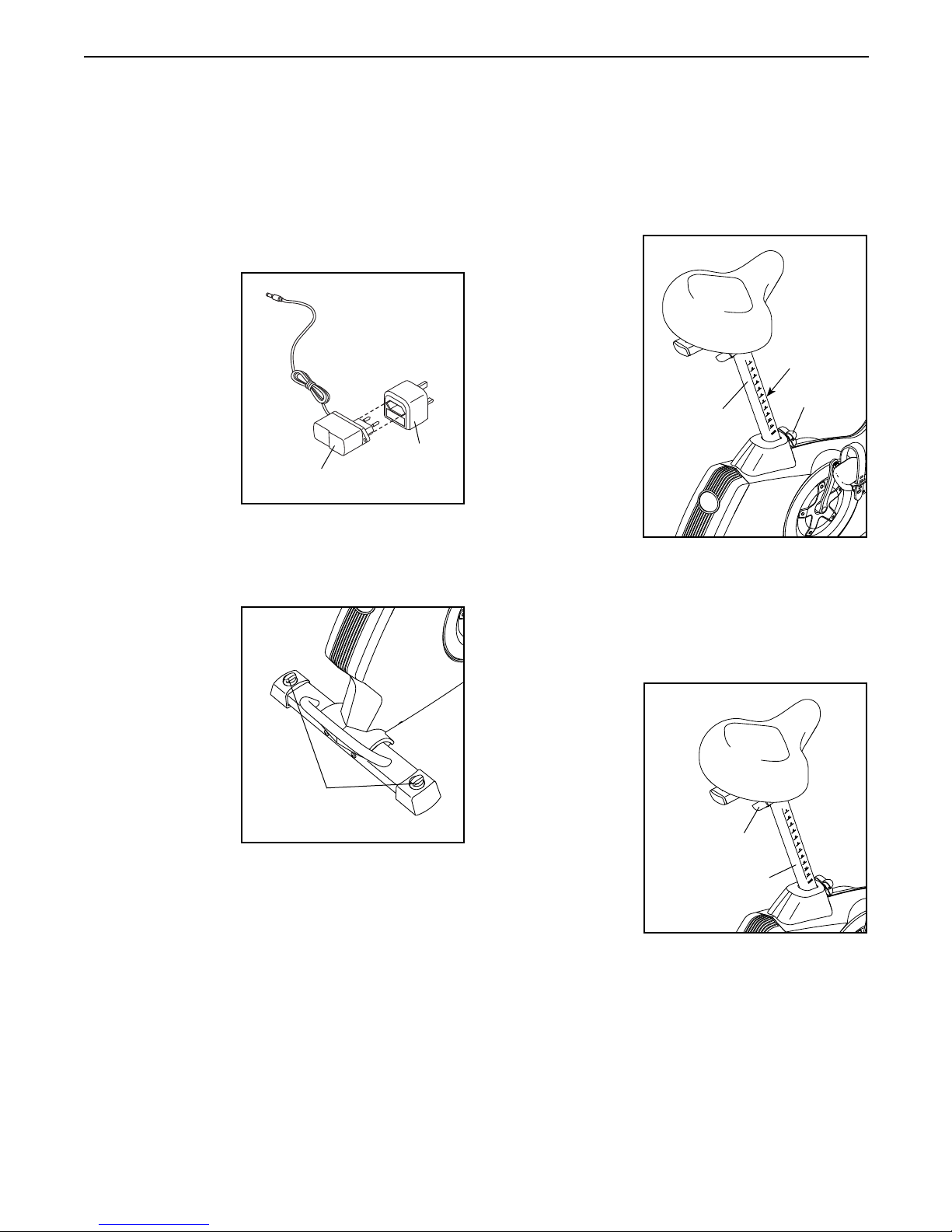
HOW TO PLUG IN THE POWER ADAPTER
IMPORTANT: If the exercise bike has been exposed
to cold temperatures, allow it to warm to room
temperature before you plug in the power adapter.
If you do not do this, you may damage the console
displays or other electronic components.
Plug the power
adapter into the
receptacle on
the frame of the
exercise bike.
Next, plug the
power adapter into
the plug adapter.
Then, plug the
plug adapter
into an appropriate outlet that is
properly installed
in accordance with
all local codes and ordinances.
HOW TO LEVEL THE EXERCISE BIKE
If the exercise
bike rocks slightly
on your floor
during use, turn
one or both of the
leveling knobs on
the rear stabilizer
and adjust the
leveling feet until
the rocking motion
is eliminated.
Power Adapter
Leveling
Knobs
Plug
Adapter
HOW TO ADJUST THE HEIGHT OF THE SEAT
For effective exercise, the seat should be at the proper
height. As you pedal, there should be a slight bend in
your knees when the pedals are in the lowest position.
To adjust the seat,
first loosen the
adjustment knob
a few turns. Next,
pull the knob
outward, slide the
seat post upward
or downward to
the desired position, and then
release the knob.
Move the seat
post upward
or downward
slightly to make
sure that the
knob is engaged
in one of the
adjustment holes in the seat post. Then, tighten the
knob.
HOW TO ADJUST THE HORIZONTAL POSITION OF
THE SEAT
To adjust the
horizontal position of the seat,
first loosen the
seat adjustment
knob a few turns.
Then, move the
seat forward or
backward to the
desired position,
and firmly tighten
the knob.
Seat
Post
Seat Knob
Seat Post
Holes
Knob
13
Page 14
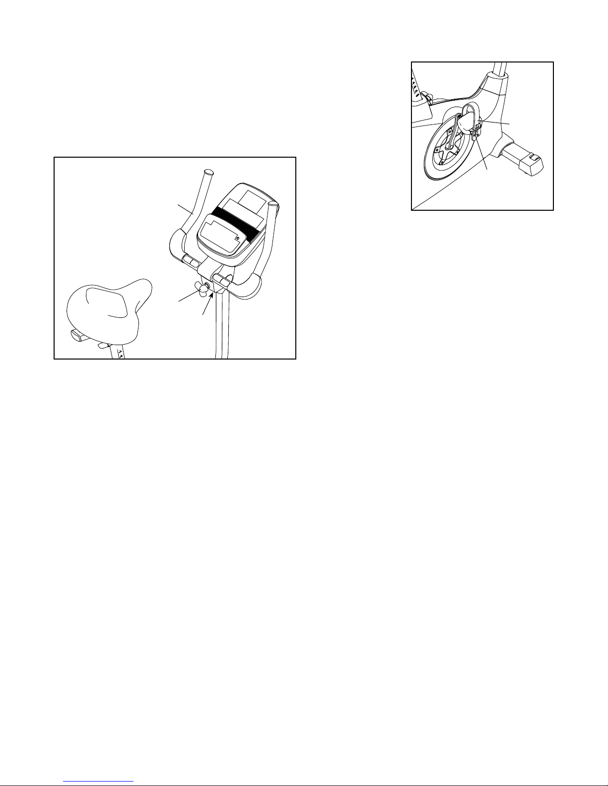
HOW TO ADJUST THE ANGLE OF THE
HANDLEBAR
To adjust the angle of the handlebar, first loosen the
adjustment knob a few turns. Next, pull the knob outward, pivot the handlebar to the desired angle, and
then release the knob into an adjustment hole. Make
sure that the knob is engaged in one of the adjustment holes. Then, tighten the knob.
Handlebar
Knob
Holes
HOW TO ADJUST THE PEDAL STRAPS
To adjust the
pedal straps, first
pull the ends of
the straps off the
tabs on the pedals. Then, adjust
the straps to the
desired position,
and press the
ends of the straps
onto the tabs.
Tab
Strap
14
Page 15
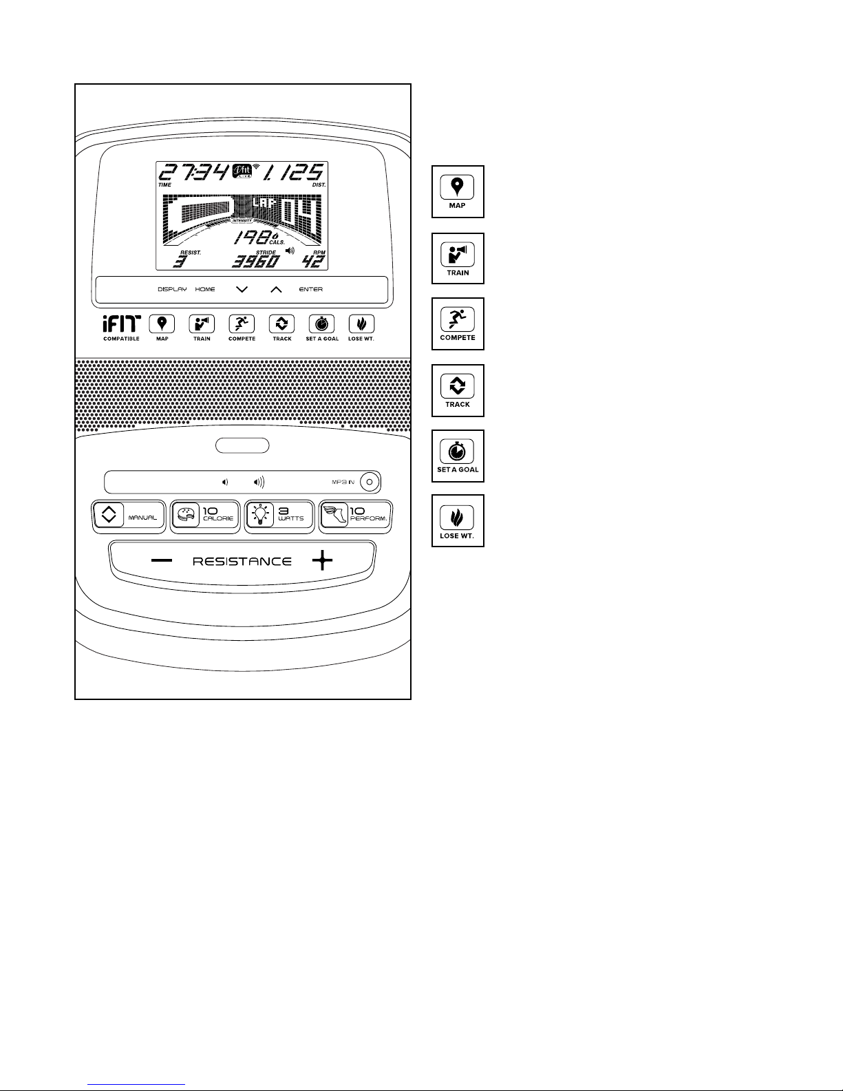
CONSOLE DIAGRAM MAKE YOUR FITNESS GOALS A REALITY WITH
IFIT.COM
With your new iFit-compatible fitness equipment, you
can use an array of features on iFit.com to make your
fitness goals a reality:
Exercise anywhere in the world with
customizable Google Maps.
Download training workouts designed to
help you reach your personal goals.
Measure your progress by competing
against other users in the iFit community.
Upload your workout results to the iFit
cloud and track your accomplishments.
Set calorie, time, or distance goals for your
workouts.
Choose and download sets of weight-loss
workouts.
Go to iFit.com to learn more.
15
Page 16

FEATURES OF THE CONSOLE
The advanced console offers an array of features
designed to make your workouts more effective and
enjoyable.
When you use the manual mode of the console, you
can change the resistance of the pedals with the touch
of a button. While you exercise, the console will display
continuous exercise feedback. You can also measure
your heart rate using the handgrip heart rate monitor or
the chest heart rate monitor.
The console offers twenty onboard workouts—ten
calorie workouts and ten performance workouts. Each
workout automatically changes the resistance of the
pedals as it guides you through an effective workout.
You can also set a calories, distance, or time goal.
The console also offers three watts workouts that
change the resistance of the pedals to keep your
power output near a watts goal.
The console also features an iFit mode that enables
the console to communicate with your wireless network
through an optional iFit module. With the iFit mode,
you can download personalized workouts, create your
own workouts, track your workout results, race against
other iFit users, and access many other features.
To purchase an iFit module at any time, go to
www.iFit.com or call the telephone number on the
front cover of this manual.
You can even connect your MP3 player or CD player
to the console sound system and listen to your favorite
music or audio books while you exercise.
To use the manual mode, see page 17. To use
an onboard workout, see page 19. To use a
set-a-goal workout, see page 20. To use a watts
workout, see page 21. To use an iFit workout,
see page 22. To use the sound system, see page
23. To change console settings, see page 24.
Note: If there is a sheet of plastic on the display,
remove the plastic.
16
Page 17
HOW TO USE THE MANUAL MODE
1. Begin pedaling or press any button on the
console to turn on the console.
When you turn on the console, the display will turn
on. The console will then be ready for use.
Calories per Hour (Cals./Hr)—This display mode
will show the approximate number of calories you
are burning per hour.
Distance (Dist.)—This display mode will show
the distance that you have pedaled in miles or
kilometers.
2. Select the manual mode.
Press the Manual button on the console to select
the manual mode.
If a wireless iFit module is not inserted into the con-
sole and connected to iFit, the manual mode will be
selected automatically.
3. Change the resistance of the pedals as desired.
As you pedal, change the resistance of the pedals
by pressing the Resistance increase and decrease
buttons.
Note: After you press a button, it will take a
moment for the pedals to reach the selected resistance level.
4. Follow your progress with the display.
The display can show the following workout
information:
Pulse—This display mode will show your heart rate
when you use the handgrip heart rate monitor or
the chest heart rate monitor (see step 5).
Resistance (Resist.)—This display mode will
show the resistance level of the pedals for a few
seconds each time the resistance level changes.
Speed—This display mode will show your pedaling
speed in miles per hour or kilometers per hour.
Time—When the manual mode is selected, this
display mode will show the elapsed time. When a
workout is selected, this display mode will show the
time remaining in the workout.
Watts—This display mode will show your power
output in watts.
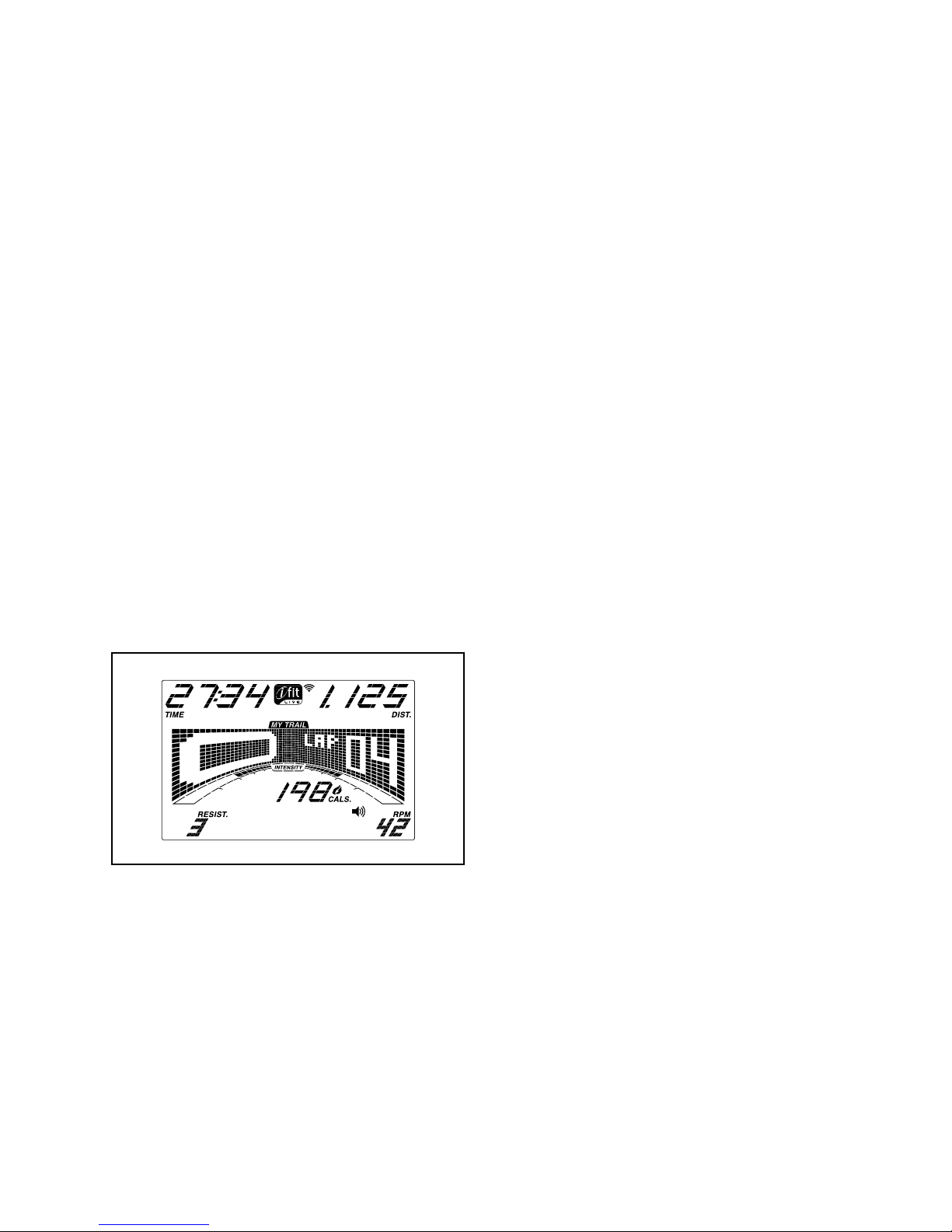
The matrix offers several display tabs. Press the
Display button until the desired tab is shown. You
can also press the increase and decrease buttons
next to the Enter button.
Speed—This tab will show a profile of the speed
settings of the workout. A new segment will appear
at the end of each minute.
Calories (Cals.)—This display mode will show the
approximate number of calories you have burned.
My Trail—This tab will show a track that represents
1/4 mile (400 m). As you exercise, the flashing
rectangle will show your progress. The My Trail tab
will also show the number of laps you complete.
Calorie—This tab will show the approximate
amount of calories you have burned. The height of
each segment represents the amount of calories
burned during that segment.
17
Page 18
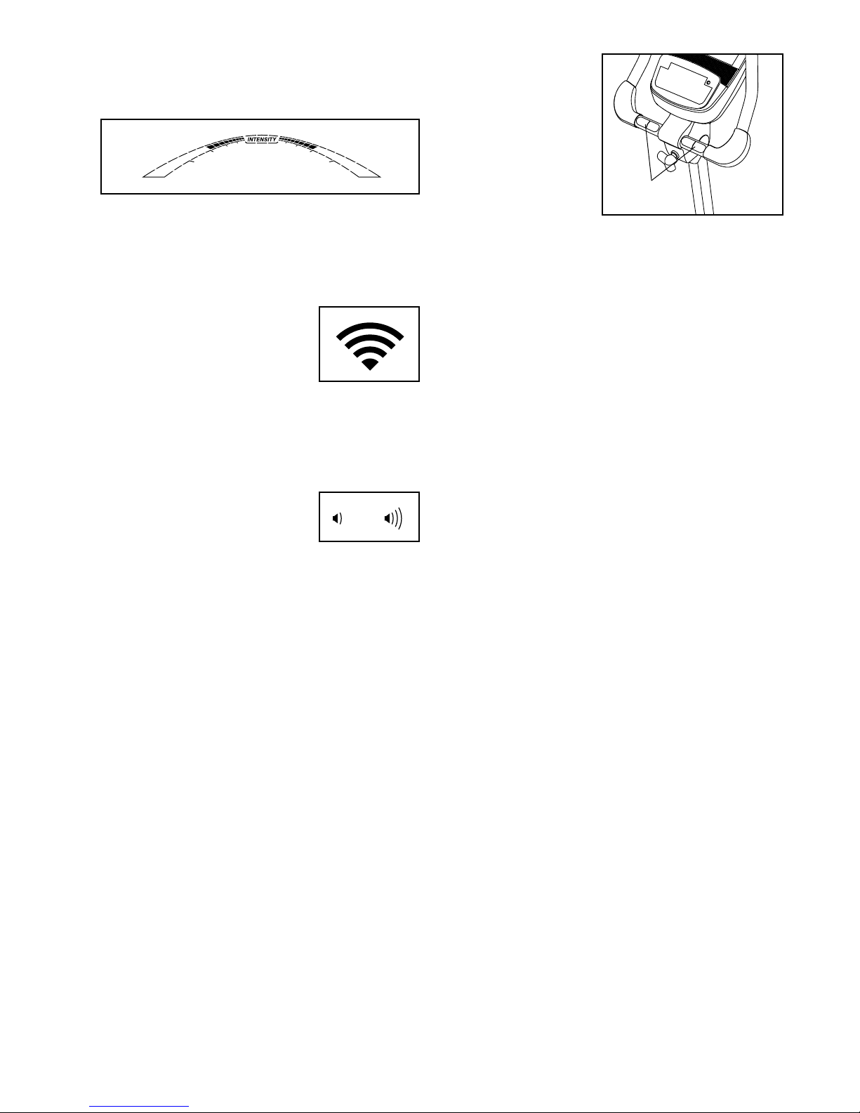
As you exercise, the workout intensity level bar
will indicate the approximate intensity level of your
exercise.
Press the Home button to return to the default
menu (see HOW TO CHANGE CONSOLE
SETTINGS on page 24 to set the default menu).
If necessary, press the Home button again.
If there are
sheets of plastic on the metal
contacts on the
handgrip heart
rate monitor,
remove the plastic. To measure
your heart rate,
hold the handgrip
heart rate monitor
with your palms resting against the contacts. Avoid
moving your hands or gripping the contacts
tightly.
Contacts
When a wireless iFit module is
connected, the wireless symbol at the top of the display will
show the strength of your wireless signal. Four arcs indicate
full signal strength.
To exit the manual mode or a workout, press the
Home button. If necessary, press the Home button
again.
Change the volume level of
the console by pressing the
volume increase and decrease
buttons.
5. Measure your heart rate if desired.
To use the included chest heart rate monitor, see
page 12. To use the handgrip heart rate monitor, follow the instructions below. IMPORTANT: If
you use both heart rate monitors at the same
time, the console will not display your heart
rate accurately.
When your pulse is detected, your heart rate will
be shown in the display. For the most accurate
heart rate reading, hold the contacts for at least 15
seconds.
If the display does not show your heart rate, make
sure that your hands are positioned as described.
Be careful not to move your hands excessively or
to squeeze the contacts tightly. For optimal performance, clean the contacts using a soft cloth; never
use alcohol, abrasives, or chemicals to clean
the contacts.
6. When you are finished exercising, the console
will turn off automatically.
If the pedals do not move for several seconds, a
tone will sound, the console will pause, and the
time will flash in the display. To resume your workout, simply resume pedaling.
If the pedals do not move for several minutes and
the buttons are not pressed, the console will turn
off and the display will be reset.
18
Page 19
HOW TO USE AN ONBOARD WORKOUT
1. Begin pedaling or press any button on the
console to turn on the console.
When you turn on the console, the display will turn
on. The console will then be ready for use.
2. Select an onboard workout.
To select an onboard workout, press the 10 Calorie
button or the 10 Perform. button repeatedly until
the desired workout appears in the display.
resistance level and/or target speed is programmed
for the next segment, the resistance level and/or
target speed will appear in the display for a few
seconds to alert you. The resistance of the pedals
will then change.
As you exercise, you will be prompted to keep your
pedaling speed near the target speed for the current segment. When an upward-pointing arrow
appears in the display, increase your speed.
When a downward-pointing arrow appears,
decrease your speed. When no arrow appears,
maintain your current speed.
When you select an onboard workout, the display
will show the duration of the workout and the name
of the workout. A profile of the speed settings of the
workout will appear in the matrix.
The maximum resistance level and the maximum
speed for the workout will also appear in the
display.
3. Begin pedaling to start the workout.
Each workout is divided into one-minute seg-
ments. One resistance level and one target speed
is programmed for each segment. Note: The same
resistance level and/or target speed may be programmed for consecutive segments.
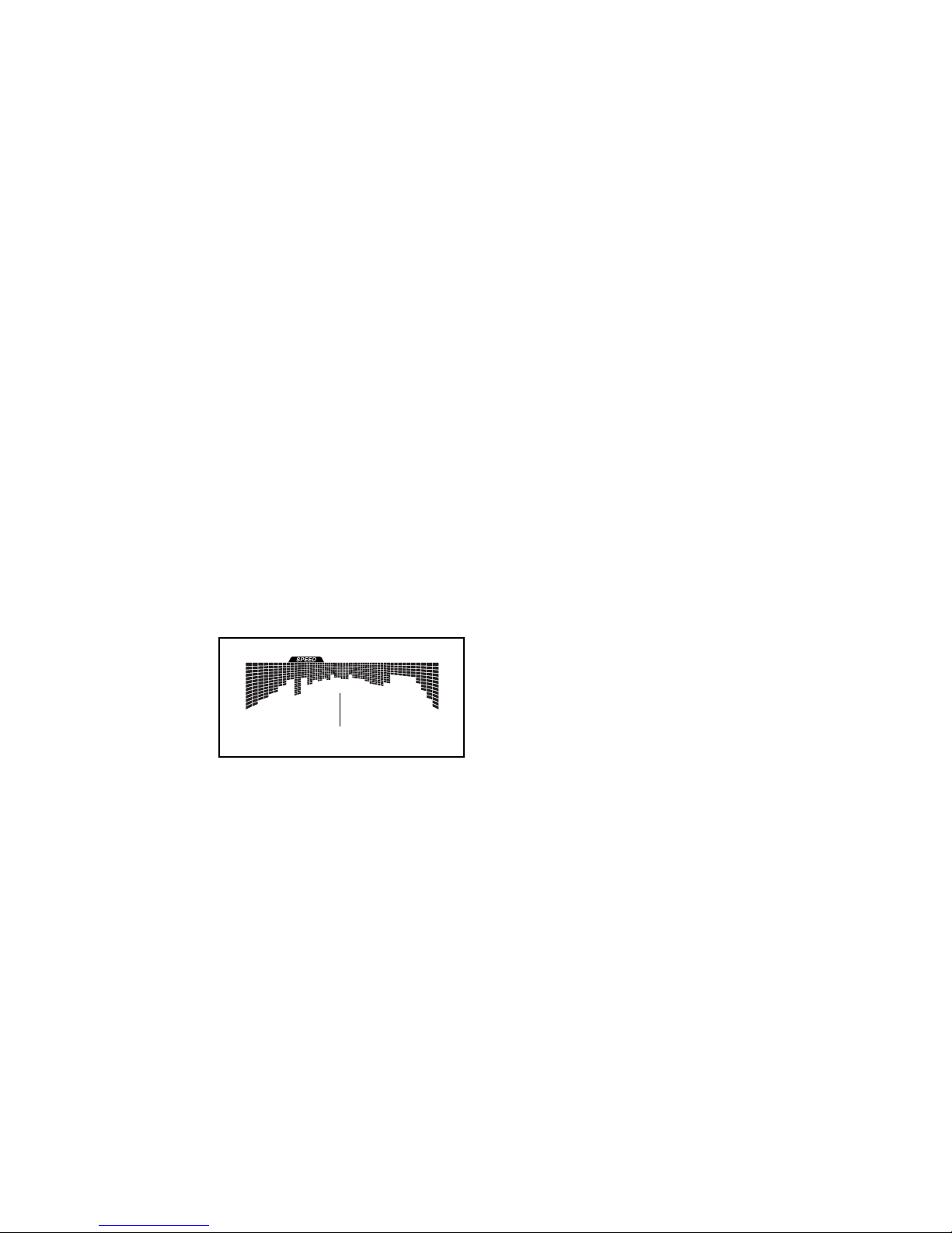
During
the workout, the
profile on
the speed
tab will
show your
progress.
The flashing segment of the profile represents the
current segment of the workout. The height of the
flashing segment indicates the target speed for the
current segment.
Profile
IMPORTANT: The target speed is intended only
to provide motivation. Your actual pedaling
speed may be slower than the target speed.
Make sure to pedal at a speed that is comfortable for you.
If the resistance level for the current segment is
too high or too low, you can manually override
the setting by pressing the Resistance buttons.
IMPORTANT: When the current segment of the
workout ends, the pedals will automatically
adjust to the resistance level programmed for
the next segment.
The workout will continue in this way until the last
segment ends. To stop the workout at any time,
stop pedaling. The time will flash in the display. To
resume the workout, simply resume pedaling.
4. Follow your progress with the display.
See step 4 on page 17.
5. Measure your heart rate if desired.
See step 5 on page 18.
6. When you are finished exercising, the console
will turn off automatically.
At the end of each segment of the workout, a
series of tones will sound and the next segment
of the profile will begin to flash. If a different
See step 6 on page 18.
19
Page 20

HOW TO USE A SET-A-GOAL WORKOUT
1. Begin pedaling or press any button on the
console to turn on the console.
When you turn on the console, the display will turn
on. The console will then be ready for use.
2. Set a calories, distance, or time goal.
To set a calories, distance, or time goal, first press
the Set A Goal button.
Next, press the increase and decrease buttons
next to the Enter button until the name of the
desired goal appears in the display. Then, press
the Enter button.
Then, press the increase and decrease buttons
next to the Enter button to set the desired goal.
Make sure to pedal at a speed that is comfortable for you.
Note: The calorie goal is an estimate of the
number of calories that you will burn during
the workout. The actual number of calories that
you burn will depend on various factors such
as your weight. In addition, if you manually
change the resistance during the workout, the
number of calories you burn will be affected.
The workout will continue in this way until the calo-
ries, distance, or time goal is reached. To stop the
workout at any time, stop pedaling. The time will
flash in the display. To resume the workout, simply
resume pedaling.
4. Follow your progress with the display.
See step 4 on page 17.
3. Begin pedaling to start the workout.
As you exercise, a target speed may appear in
the display to help you reach your goal. Keep
your pedaling speed near the target speed.
IMPORTANT: The target speed is intended only
to provide motivation. Your actual pedaling
speed may be slower than the target speed.
5. Measure your heart rate if desired.
See step 5 on page 18.
6. When you are finished exercising, the console
will turn off automatically.
See step 6 on page 18.
20
Page 21

HOW TO USE A WATTS WORKOUT
1. Begin pedaling or press any button on the
console to turn on the console.
When you turn on the console, the display will turn
on. The console will then be ready for use.
2.
Select a watts workout.
To select a watts workout, first press the 3 Watts
button repeatedly until the desired workout
appears in the display.
If you select watts workout 1, the words SET
WATT GOAL will appear in the display.
If you select watts workout 2 or 3, the workout
time and a profile for the workout will appear in the
display.
3. If you selected watts workout 1, enter a watts
goal setting.
During watts workout 1, the same watts goal will
be programmed for all segments of the workout.
Press the increase and decrease buttons next to
the Enter button to enter the desired watts goal.
4. Begin pedaling to start the workout.
Watts workout 2 or 3 is divided into one-minute
segments. One resistance level and one watts
goal are programmed for each segment. Note: The
same resistance level and/or watts goal may be
programmed for consecutive segments.
The workout profile will show your progress. The
flashing segment of the profile represents the current segment of the workout. The height of the
flashing segment indicates the resistance level for
the current segment.
As you exercise, pedal at the appropriate speed to
keep your watts output near the watts goal for the
segment.
When the first segment of the workout ends, the
resistance level and the watts goal for the second
segment will appear in the display for a few seconds to alert you. The next segment of the profile
will begin to flash, and the pedals will automatically
adjust to the resistance level for the next segment.
If the resistance level for the current segment is
too high or too low, you can manually override
the setting by pressing the Resistance buttons.
IMPORTANT: When the current segment of the
workout ends, the pedals will automatically
adjust to the resistance level programmed for
the next segment.
Watts workout 1 is divided into one-minute
segments. During the workout, the console will
regularly compare your watts output to the watts
goal you entered for the workout.
If your watts output is too far below or above
the watts goal, the resistance of the pedals will
automatically increase or decrease to bring your
watts output closer to the watts goal. Each time
the resistance changes, the resistance level will
appear in the display for a few seconds to alert
you.
If the watts goal is too high or too low, you can
manually override the setting by pressing the
increase and decrease buttons next to the Enter
button.
The workout will continue in this way until the last
segment ends. To stop the workout at any time,
stop pedaling. The time will flash in the display. To
resume the workout, simply resume pedaling.
5. Follow your progress with the display.
See step 4 on page 17.
6. Measure your heart rate if desired.
See step 5 on page 18.
7. When you are finished exercising, the console
will turn off automatically.
See step 6 on page 18.
21
Page 22

HOW TO USE AN IFIT WORKOUT
4. Select an iFit workout.
You must have an iFit module to use an iFit workout.
To purchase an iFit module at any time, go to
www.iFit.com or call the telephone number on the
front cover of this manual.
Note: To use an iFit module, you must have access
to a computer with an internet connection and a USB
port. You will also need an iFit.com membership. To
use a wireless iFit module, you must also have your
own wireless network including an 802.11b/g/n router
with SSID broadcast enabled (hidden networks are not
supported).
IMPORTANT: To satisfy exposure compliance
requirements, the antenna and transmitter in the
iFit module must be at least 8 in. (20 cm) from all
persons and must not be near or connected to any
other antenna or transmitter.
1. Begin pedaling or press any button on the
console to turn on the console.
When you turn on the console, the display will turn
on. The console will then be ready for use.
To download an iFit workout in your schedule,
press the Map, Train, or Lose Wt. button to download the next workout of that type in your schedule.
To download the next workout in your schedule,
press the iFit button. Note: You may be able to
access demo workouts through these options, even
if you do not insert an iFit module.
To compete in a race that you have previously
scheduled, press the Compete button.
To re-run a recent iFit workout from your sched-
ule, first press the Track button. Next, press the
increase and decrease buttons to select the
desired workout. Then, press the Enter button to
start the workout.
To use a set-a-goal workout, press the Set Goal
button (see page 20).
Note: Before some workouts will download, you
must add them to your schedule on iFit.com.
For more information about the iFit workouts,
please go to www.iFit.com.
2. Make sure that the iFit module is inserted in the
console.
To use an iFit workout, make sure that the iFit mod-
ule is inserted in the console.
3. Select a user.
If more than one user is registered with your
iFit.com membership, you can switch users in the
iFit main screen. Press the increase and decrease
buttons next to the Enter button to select a user.
When you select an iFit workout, the display will
show the duration of the workout and the approximate number of calories you will burn. The display
may also show the name of the workout. If you
select a competition workout, the display may
count down to the beginning of the race.
Note: The calorie goal is an estimate of the
number of calories that you will burn during
the workout. The actual number of calories that
you burn will depend on various factors such
as your weight. In addition, if you manually
change the resistance during the workout, the
number of calories you burn will be affected.
22
Page 23
5. Start the workout.
HOW TO USE THE SOUND SYSTEM
See step 3 on page 19.
During some workouts, the voice of a personal
trainer will guide you through your workout. You
can select an audio setting for your personal trainer
(see HOW TO CHANGE CONSOLE SETTINGS on
page 24).
To stop the workout at any time, stop pedaling. The
time will flash in the display. To resume the workout, simply resume pedaling.
6. Follow your progress with the display.
See step 4 on page 17.
7. Measure your heart rate if desired.
See step 5 on page 18.
8. When you are finished exercising, the console
will turn off automatically.
See step 6 on page 18.
To play music or audio books through the console
sound system while you exercise, plug your audio
cable into the jack on the console and into a jack on
your MP3 player or CD player; make sure that your
audio cable is fully plugged in.
Next, press the play button on your
MP3 player or CD player. Adjust
the volume level using the volume
increase and decrease buttons on
the console or the volume control
on your MP3 player or CD player.
For more information about iFit, please go to
www.iFit.com.
23
Page 24

HOW TO CHANGE CONSOLE SETTINGS
The console features a user mode that allows you to
view usage information, select a unit of measurement,
and adjust the contrast level of the display.
When an iFit module is connected to the console, you
can also use the user mode to choose an audio setting for the voice of the personal trainer, set a default
menu, check the status of the iFit module, and check
for downloads.
If no module is connected, the display will show
the words NO IFIT MODULE. If no module is connected, go to step 10.
6. Select an audio setting for the voice of the
personal trainer if desired.
Press the decrease button to view the audio setting
for the voice of the personal trainer. The currently
selected audio setting for the voice of the personal
trainer will appear in the display.
1. Select the user mode.
To select the user mode, press and hold down the
Display button for a few seconds until the user
mode appears in the display.
2. View usage information.
The display will show the total number of hours that
the exercise bike has been used. The display will
also show the total distance (in miles or kilometers)
that has been pedaled on the exercise bike.
3. Select a unit of measurement if desired.
The word ENGLISH for English miles or the word
METRIC for metric kilometers will appear in the
display to indicate the currently selected unit of
measurement.
To change the unit of measurement, press the
Enter button repeatedly to select the desired unit of
measurement.
4. Adjust the contrast level of the display if
desired.
Press the decrease button to view the contrast
level. The currently selected contrast level will
appear in the display. Press the Resistance
increase and decrease buttons to adjust the contrast level.
5. Determine if an iFit module is connected to the
console.
To change the audio setting, press the Enter button
repeatedly to turn the voice of the personal trainer
ON or OFF.
7. Set the default menu if desired.
Press the decrease button to view the default menu
setting. The default menu is the menu that will
appear when you turn on the console. Press the
Enter button repeatedly to select the manual mode
menu or the iFit menu as the default menu.
8. Check the status of the iFit module if desired.
Press the decrease button to view the iFit sta-
tus display. The words CHECK WIFI STATUS or
CHECK USB STATUS will appear in the display.
Then, press the Enter button. After a few seconds,
the status of the iFit module will appear in the display. To exit this display, press and hold down the
Display button for a few seconds.
9. Check for downloads if desired.
Press the decrease button to view the downloads
display. The words SEND/RECEIVE DATA will
appear in the display.
Then, press the Enter button. The console will then
check for iFit workouts and firmware downloads.
10. Exit the user mode.
Press the Display button to exit the user mode.
If an iFit module is connected to the console, the
display will show the words WIFI MODULE or USB
MODULE.
24
Page 25
MAINTENANCE AND TROUBLESHOOTING
Inspect and tighten all parts of the exercise bike regularly. Replace any worn parts immediately.
To clean the exercise bike, use a damp cloth and a
small amount of mild soap. IMPORTANT: To avoid
damage to the console, keep liquids away from
the console and keep the console out of direct
sunlight.
CONSOLE TROUBLESHOOTING
If lines appear in the console display, see step 4 on
page 24 and adjust the contrast level of the display.
If the console does not display your heart rate when
you use the handgrip heart rate monitor, see step 5 on
page 18.
If the console does not display your heart rate
when you use the chest heart rate monitor, see
TROUBLESHOOTING on page 12.
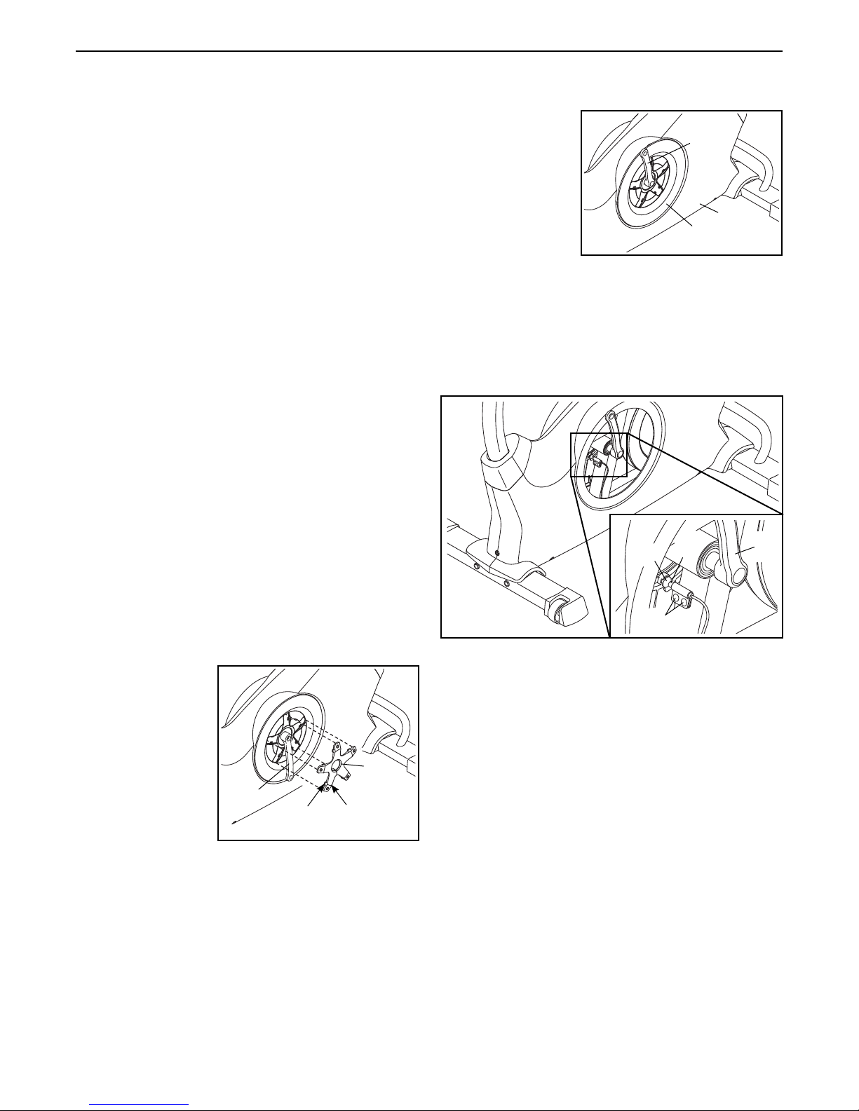
HOW TO ADJUST THE REED SWITCH
If the console does not display correct feedback, the
reed switch should be adjusted. To adjust the reed
switch, you must first remove the left pedal, the left
disc cover, and the left pedal disc (see the instructions
below).
Next, rotate the
Left Crank Arm
(20) to a vertical
position with the
end of the Left
Crank Arm pointing upward.
Rotate the left Pedal Disc (17) clockwise to release it
from the Left Shield (11). Then, work the left Pedal Disc
upward and remove it from the Left Crank Arm (20).
Locate the Reed Switch (57). Loosen, but do not
remove, the two M4 x 13mm Flange Screws (63).
55
57
20
11
17
20
Using an adjustable wrench, turn the left pedal clockwise and remove it.
Rotate the Left
Crank Arm (20) to
a vertical position
with the end of the
Left Crank Arm
pointing downward as shown.
20
Tab
Using a flat screwdriver, release the tabs on each point
of the left Disc Cover (18). Carefully work the left Disc
Cover over the Left Crank Arm (20) and remove the left
Disc Cover.
18
Tab
63
Next, rotate the Left Crank Arm (20) until a Magnet (55)
is aligned with the Reed Switch (57). Slide the Reed
Switch slightly toward or away from the Magnet. Then,
retighten the M4 x 13mm Flange Screws (63).
Rotate the Left Crank Arm (20) for a moment. Repeat
these actions until the console displays correct
feedback.
When the reed switch is correctly adjusted, reattach
the left pedal disc, the left disc cover, and the left
pedal.
25
Page 26
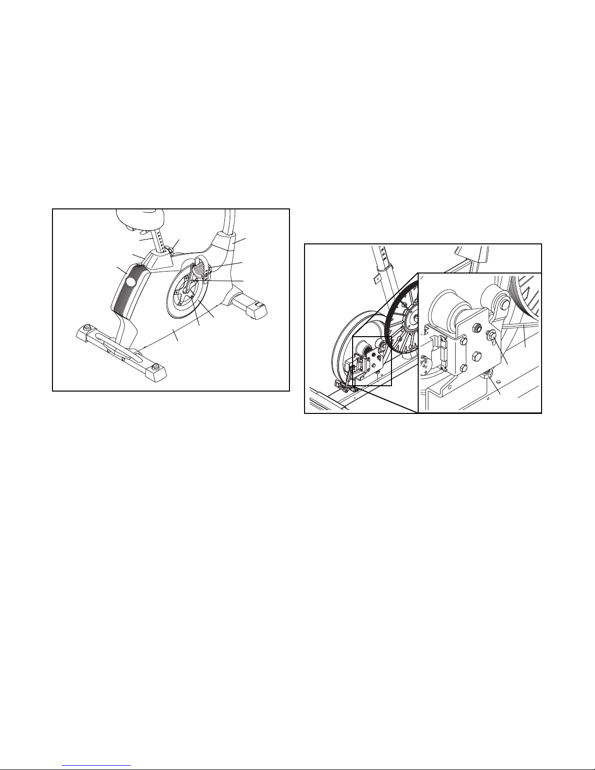
HOW TO ADJUST THE DRIVE BELT
If you can feel the pedals slip while you are pedaling,
even when the resistance is adjusted to the highest
level, the drive belt may need to be adjusted.
To adjust the drive belt, you must first remove the
right pedal, the seat post, the top shield cover, the
rear shield cover, the front shield cover, the right disc
cover, the right pedal disc, and the right shield (see the
instructions below).
Using an adjustable wrench, turn the Right Pedal (21)
counterclockwise and remove it.
6
8
9
27
7
21
19
Next, rotate the Right Crank Arm (19) to a vertical
position with the end of the Right Crank Arm pointing
upward.
Rotate the right Pedal Disc (17) clockwise to
release it from the Right Shield (10). Then, work the
right Pedal Disc upward and remove it from the Right
Crank Arm (19).
See the EXPLODED DRAWING on page 31 and
remove the M4 x 19mm Screws (89) and the M4 x
25mm Screws (62) from the Right and Left Shields (10,
11). Then, remove the Right Shield.
Next, loosen the M6 x 20mm Hex Screw (85). Then,
tighten the M10 x 65mm Hex Screw (86) until the Drive
Belt (54) is tight.
17
18
10
Next, remove the Adjustment Knob (27) and remove
the Seat Post (6).
Using a flat screwdriver, remove the Top Shield Cover
(8) and the Rear Shield Cover (9). Then, use the flat
screwdriver to release the Front Shield Cover (7).
Rotate the Right Crank Arm (19) to a vertical position with the end of the Right Crank Arm pointing
downward.
Using a flat screwdriver, release the tabs on each point
of the right Disc Cover (18). Carefully work the right
Disc Cover over the Right Crank Arm (19) and remove
the right Disc Cover. Note: See the drawings on page
25 for more detail.
54
85
86
When the Drive Belt (54) is tight, tighten the M6 x
20mm Hex Screw (85).
Then, reattach the right shield, the right pedal disc, the
right disc cover, the front shield cover, the rear shield
cover, the top shield cover, the seat post, and the right
pedal.
26
Page 27
EXERCISE GUIDELINES
WARNING: Before beginning this
or any exercise program, consult your physician. This is especially important for persons
over age 35 or persons with pre-existing
health problems.
The heart rate monitor is not a medical device.
Various factors may affect the accuracy of
heart rate readings. The heart rate monitor is
intended only as an exercise aid in determining heart rate trends in general.
These guidelines will help you to plan your exercise
program. For detailed exercise information, obtain a
reputable book or consult your physician. Remember,
proper nutrition and adequate rest are essential for
successful results.
EXERCISE INTENSITY
Whether your goal is to burn fat or to strengthen your
cardiovascular system, exercising at the proper intensity is the key to achieving results. You can use your
heart rate as a guide to find the proper intensity level.
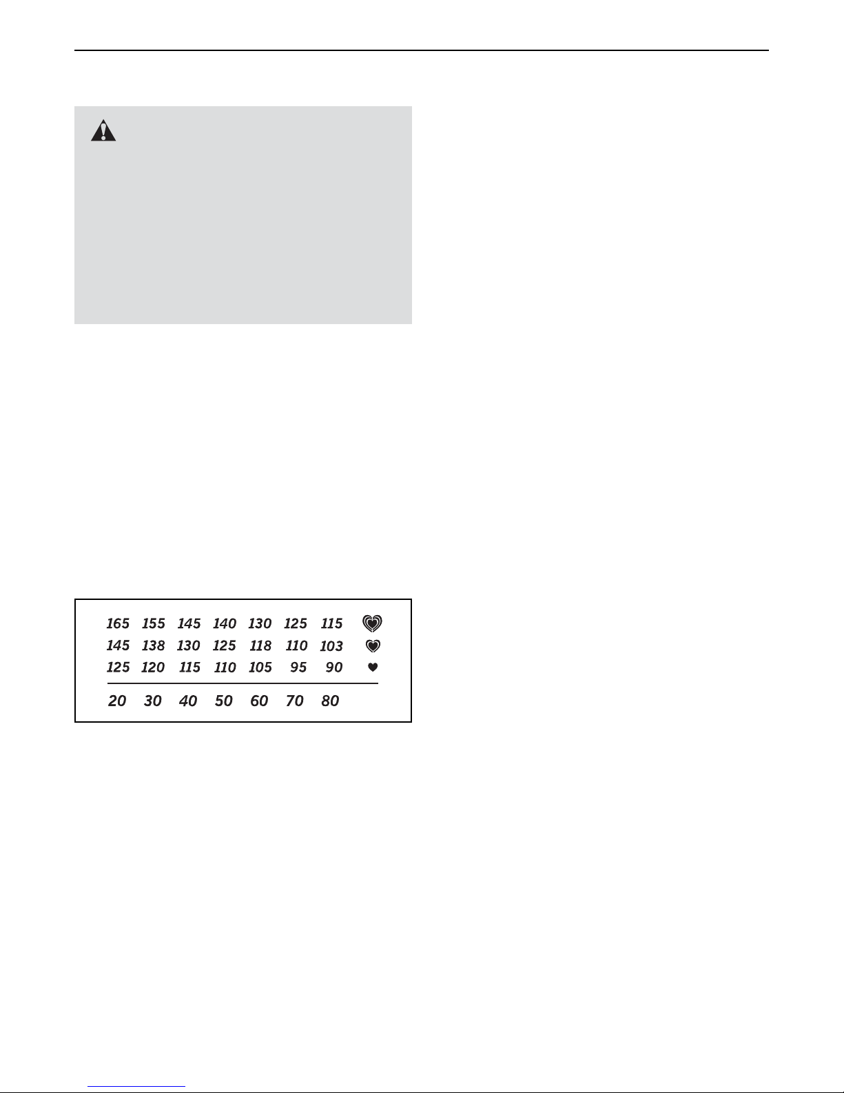
The chart below shows recommended heart rates for
fat burning and aerobic exercise.
Burning Fat—To burn fat effectively, you must exercise at a low intensity level for a sustained period of
time. During the first few minutes of exercise, your
body uses carbohydrate calories for energy. Only after
the first few minutes of exercise does your body begin
to use stored fat calories for energy. If your goal is to
burn fat, adjust the intensity of your exercise until your
heart rate is near the lowest number in your training
zone. For maximum fat burning, exercise with your
heart rate near the middle number in your training
zone.
Aerobic Exercise—If your goal is to strengthen your
cardiovascular system, you must perform aerobic
exercise, which is activity that requires large amounts
of oxygen for prolonged periods of time. For aerobic
exercise, adjust the intensity of your exercise until your
heart rate is near the highest number in your training
zone.
WORKOUT GUIDELINES
Warming Up—Start with 5 to 10 minutes of stretch-
ing and light exercise. A warm-up increases your body
temperature, heart rate, and circulation in preparation
for exercise.
Training Zone Exercise—Exercise for 20 to 30 minutes with your heart rate in your training zone. (During
the first few weeks of your exercise program, do not
keep your heart rate in your training zone for longer
than 20 minutes.) Breathe regularly and deeply as you
exercise ; never hold your breath.
To find the proper intensity level, find your age at the
bottom of the chart (ages are rounded off to the nearest ten years). The three numbers listed above your
age define your “training zone.” The lowest number is
the heart rate for fat burning, the middle number is the
heart rate for maximum fat burning, and the highest
number is the heart rate for aerobic exercise.
Cooling Down—Finish with 5 to 10 minutes of stretching. Stretching increases the flexibility of your muscles
and helps to prevent post-exercise problems.
EXERCISE FREQUENCY
To maintain or improve your condition, complete three
workouts each week, with at least one day of rest
between workouts. After a few months of regular exercise, you may complete up to five workouts each week,
if desired. Remember, the key to success is to make
exercise a regular and enjoyable part of your everyday
life.
27
Page 28
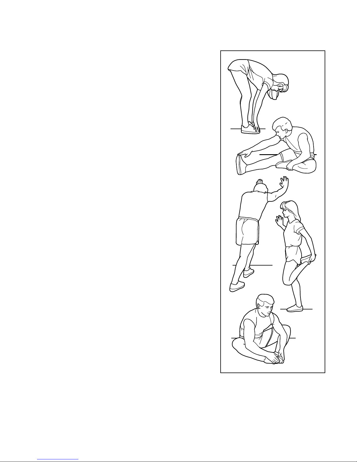
SUGGESTED STRETCHES
The correct form for several basic stretches is shown at the right. Move slowly as you stretch; never bounce.
1. Toe Touch Stretch
Stand with your knees bent slightly and slowly bend forward from
your hips. Allow your back and shoulders to relax as you reach down
toward your toes as far as possible. Hold for 15 counts, then relax.
Repeat 3 times. Stretches: Hamstrings, back of knees and back.
2. Hamstring Stretch
Sit with one leg extended. Bring the sole of the opposite foot toward
you and rest it against the inner thigh of your extended leg. Reach
toward your toes as far as possible. Hold for 15 counts, then relax.
Repeat 3 times for each leg. Stretches: Hamstrings, lower back and
groin.
3. Calf/Achilles Stretch
With one leg in front of the other, reach forward and place your
hands against a wall. Keep your back leg straight and your back foot
flat on the floor. Bend your front leg, lean forward and move your
hips toward the wall. Hold for 15 counts, then relax. Repeat 3 times
for each leg. To cause further stretching of the achilles tendons,
bend your back leg as well. Stretches: Calves, achilles tendons and
ankles.
4. Quadriceps Stretch
1
2
3
4
With one hand against a wall for balance, reach back and grasp one
foot with your other hand. Bring your heel as close to your buttocks
as possible. Hold for 15 counts, then relax. Repeat 3 times for each
leg. Stretches: Quadriceps and hip muscles.
5. Inner Thigh Stretch
Sit with the soles of your feet together and your knees outward.
Pull your feet toward your groin area as far as possible. Hold for 15
counts, then relax. Repeat 3 times. Stretches: Quadriceps and hip
muscles.
5
28
Page 29

PART LIST
Key No. Qty. Description Key No. Qty. Description
Model No. NTEVEX78612.0 R0113A
1 1 Frame
2 1 Front Stabilizer
3 1 Rear Stabilizer
4 1 Upright
5 1 Handlebar
6 1 Seat Post
7 1 Front Shield Cover
8 1 Top Shield Cover
9 1 Rear Shield Cover
10 1 Right Shield
11 1 Left Shield
12 1 Pivot Cover
13 1 Console
14 1 Right Pad
15 1 Left Pad
16 1 Pulse Sensor/Receiver
17 2 Pedal Disc
18 2 Disc Cover
19 1 Right Crank Arm
20 1 Left Crank Arm
21 1 Right Pedal/Strap
22 1 Left Pedal/Strap
23 1 Seat
24 1 Seat Carriage
25 2 Seat Post Cap
26 1 Seat Adjustment Knob
27 2 Adjustment Knob
28 1 Seat Post Sleeve
29 2 Leveling Knob
30 1 Seat Bracket
31 2 Leveling Foot
32 2 Rear Stabilizer Cap
33 1 Right Stabilizer Cap
34 1 Left Stabilizer Cap
35 2 Wheel
36 2 Foot
37 1 Heart Rate Monitor/Strap
38 1 Pulley
39 1 Crank
40 2 Crank Bearing
41 2 Snap Ring
42 1 Flywheel
43 2 M8 Washer
44 1 Flywheel Axle
45 1 Idler
46 1 Motor Bracket
47 1 Resistance Motor
48 1 Resistance Disc
49 1 Resistance Arm
50 1 M6 x 70mm Bolt Set
51 1 M6 x 60mm Bolt Set
52 1 Resistance Bracket
53 1 C-magnet
54 1 Drive Belt
55 2 Magnet
56 1 Clamp
57 1 Reed Switch/Wire
58 1 Lower Wire
59 1 Upper Wire
60 2 Wire Clamp
61 1 Pulse Wire
62 2 M4 x 25mm Screw
63 2 M4 x 13mm Flange Screw
64 2 Adjustment Nut
65 3 M8 x 17mm Flat Head Screw
66 2 Handlebar Cap
67 1 Power Adapter
68 2 Crank Cap
69 2 Upright Pivot Bushing
70 2 5/16" Flange Screw
71 4 M8 x 20mm Bolt
72 8 M8 Locknut
73 2 M8 Jam Nut
74 4 M8 x 20mm Screw
75 12 M8 Split Washer
76 4 M10 x 95mm Screw
77 1 M6 x 65mm Hex Screw
78 1 M6 Locknut
79 4 M4 x 12mm Flange Screw
80 2 M6 x 8mm Hex Screw
81 1 M5 Washer
82 1 M5 x 7mm Screw
83 1 Idler Screw
84 1 M6 Washer
85 1 M6 x 20mm Hex Screw
86 1 M10 x 65mm Hex Screw
87 1 M3.5 x 12mm Screw
88 1 M4 x 13mm Bright Screw
29
Page 30

Key No. Qty. Description Key No. Qty. Description
89 16 M4 x 19mm Screw
90 8 M4 x 16mm Screw
91 2 M4 x 5mm Bright Screw
92 2 Handlebar Pivot Bushing
93 6 M4 x 19mm Flat Head Screw
Note: Specifications are subject to change without notice. For information about ordering replacement parts, see
the back cover of this manual. *These parts are not illustrated.
94 1 Snap Ring
95 1 Power Receptacle/Wire
* – Assembly Tool
* – User’s Manual
30
Page 31
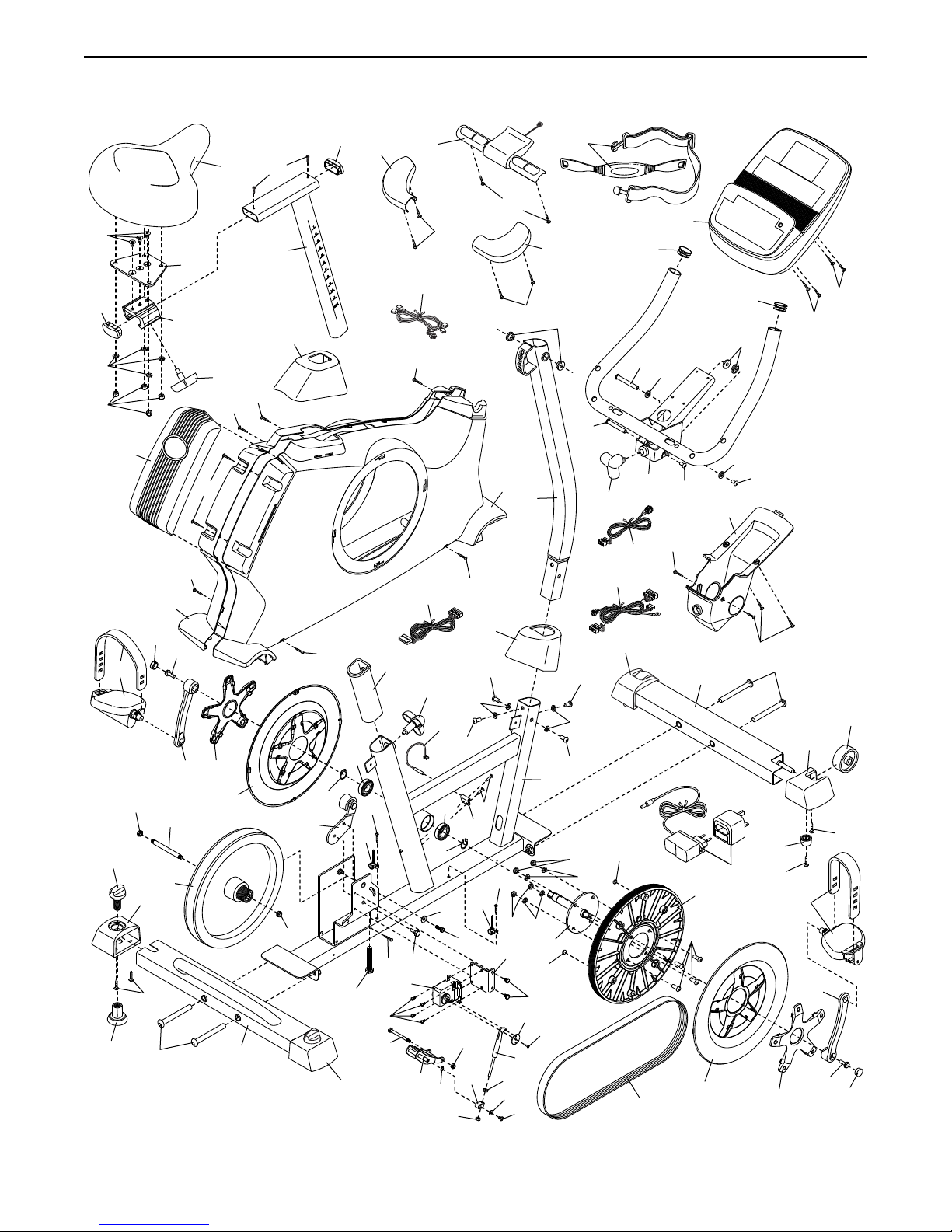
EXPLODED DRAWING
Model No. NTEVEX78612.0 R0113A
65
25
75
72
29
31
22
9
73
32
68
89
76
11
44
42
24
70
30
89
20
89
18
26
17
23
89
25
15
91
6
8
62
89
40
41
45
73
3
89
60
86
79
77
32
28
88
47
83
62
53
16
61
59
27
41
94
93
57
40
64
84
74
89
75
85
78
52
93
93
10
7
74
63
56
89
60
72
46
48
49
64
81
82
4
75
55
80
14
1
39
87
69
74
37
75
72
51
74
75
27
58
55
34
95
50
54
66
5
43
90
13
51
71
2
38
17
12
67
92
43
66
50
90
76
36
89
18
90
90
35
33
89
21
19
70
68
31
Page 32
ORDERING REPLACEMENT PARTS
To order replacement parts, please see the front cover of this manual. To help us assist you, be prepared to
provide the following information when contacting us:
•themodelnumberandserialnumberoftheproduct(seethefrontcoverofthismanual)
•thenameoftheproduct(seethefrontcoverofthismanual)
•thekeynumberanddescriptionofthereplacementpart(s)(seethePARTLISTandtheEXPLODED
DRAWING near the end of this manual)
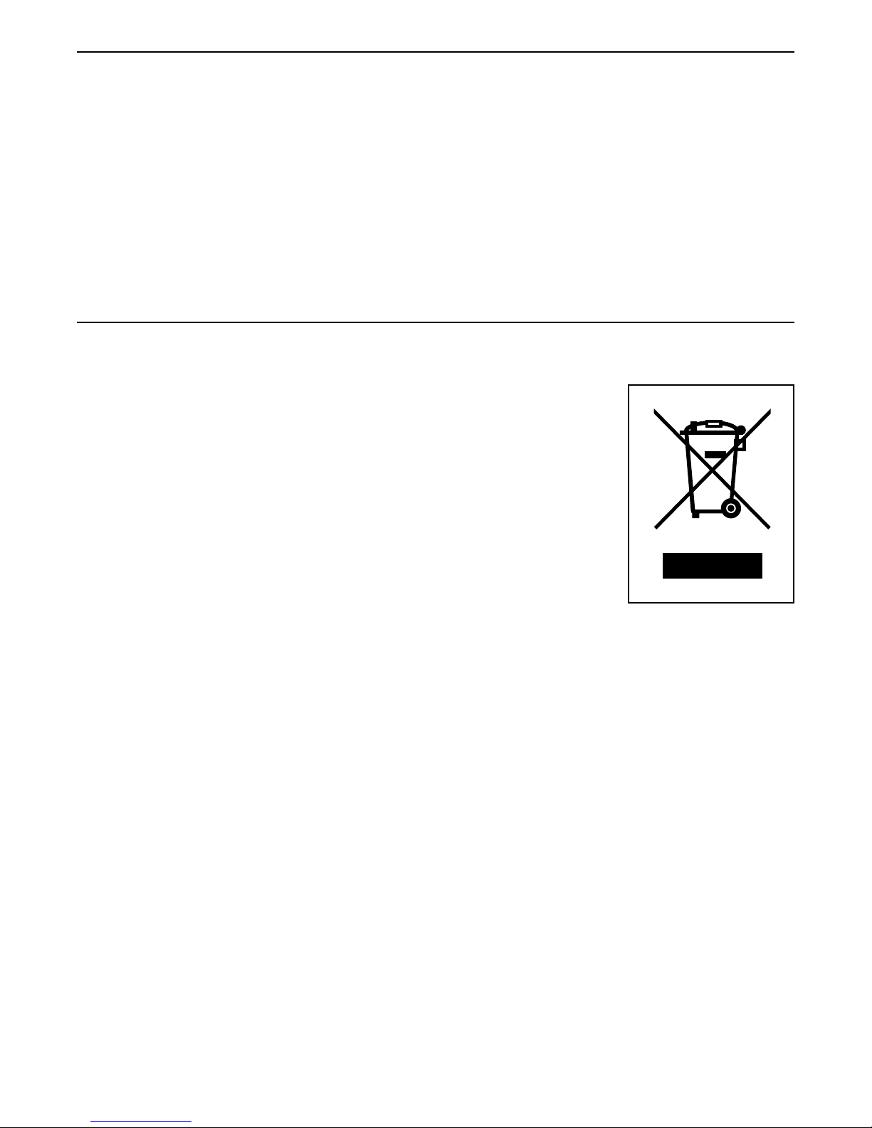
RECYCLING INFORMATION
This electronic product must not be disposed of in municipal waste. To preserve the environment, this product must be recycled after its useful life as
required by law.
Please use recycling facilities that are authorized to collect this type of waste in
your area. In doing so, you will help to conserve natural resources and improve
European standards of environmental protection. If you require more information
about safe and correct disposal methods, please contact your local city office or the
establishment where you purchased this product.
Part No. 338578 R0113A Printed in China © 2013 ICON IP, Inc.
 Loading...