


THANK YOU FOR PURCHASING
THIS NORDIC LEGEND POWER
ICE AUGER COMBO!
IT IS IMPORTANT THAT YOU READ ALL
ASSEMBLY, USAGE AND SAFETY
INSTRUCTIONS!
PLEASE TAKE TIME TO READ THIS
MANUAL AND FOLLOW ALL INSTRUC-
TIONS TO ENHANCE YOUR ICE FISHING
EXPERIENCE!
THEN PLEASE REGISTER YOUR
PURCHASE AT
WWW.NORDIC-LEGEND.COM
OR BY FILLING OUT AND MAILING IN
YOUR WARRANTY CARD.
POWER ICE AUGER COMBO
POWER HEAD AND 8” BIT
• Engine 33cc 2-cycle
• Heavy-duty transmission
• Protective mufer guard
• Fingertip throttle control with
safety switch
• High alloy carbon steel blades
• Heavy-duty blade cover
• Centering ring engineered for
optimal performance
8000
RPM
42”
LENGTH
47:1
GEARS
8”
DIAMETER

CARE AND USE MANUAL
MODEL B33Z08 & B33Z10
POWER ICE AUGER
•
CONGRATULATIONS!
on purchasing your new NORDIC LEGEND POWER ICE AUGER and welcome to the world of Nordic Legend Ice Fishing. We
know that you are anxious to get right to work and start using your new Ice Auger, but before you do, it is important that
you take a few moments and familiarize yourself with your new unit and its assembly and operating instructions.
Please read your owner’s manual and take time to save time. We have worked hard to ensure that your new unit will be one of
the most trouble-free and satisfying pieces of equipment you have ever owned. With proper care and maintenance,
your new equipment will provide many years of service. Please take the time to read this manual carefully to learn how to
correctly assemble, use and maintain your unit.
PLEASE TAKE THE NEXT STEP TO REGISTER YOUR PURCHASE BY
COMPLETING THE ENCLOSED WARRANTY CARD AND MAILING
THE CARD TO THE FOLLOWING ADDRESS:
NORDIC LEGEND
PO BOX 145
CLAYTON, WI 54004
844-688-0690
OR
BY GOING TO WWW.NORDIC-LEGEND.COM AND FINDING THE
WARRANTY ICON. CLICK ON THE WARRANTY ICON TO REGISTER YOUR PURCHASE.
CONTENTS
Registration/Introduction/Owner's Responsibility .......................................................................... 2
General Safety Rules ................................................................................................................3-5
Operation, Maintenance & Storage ..........................................................................................8-11
Troubleshooting........................................................................................................................ 12
Parts Drawings and Parts List ................................................................................................ 13-16
OWNER’S RESPONSIBILITY
• READ AND FOLLOW ALL SAFETY INSTRUCTIONS
• PAY CLOSE ATTENTION AND FULLY UNDERSTAND ALL SAFETY PRACTICES
• CAREFULLY FOLLOW ALL ASSEMBLY INSTRUCTIONS
• MAINTAIN THE UNIT ACCORDING TO DIRECTIONS AND SCHEDULE IN YOUR MANUAL
• ENSURE THAT ANYONE WHO USES THIS UNIT IS FAMILIAR WITH ALL THE CONTROLS, PARTS AND SAFETY PRECAUTIONS
TOLL FREE HELP LINE 1-844-688-0690 2

CARE AND USE MANUAL
MODEL B33Z08 & B33Z10
POWER ICE AUGER
SPECIAL MESSAGES
Throughout your manual you will nd special messages to help bring potential safety concerns to your
attention. Please read the entire manual carefully to help avoid injury and machine damage. Your manual is
meant to be a helpful tool in preventing machine damage and personal injury. It also provides helpful
operating tips and service information.
NOTE: Throughout the Manual, you will nd general information that may help you in the operation and
service of the powerhead
This symbol points out important safety instructions which if not followed could endanger
your personal safety. Read and follow all instructions in this manual before attempting to
operate this equipment
VITAL SAFETY PRECAUTIONS
Please read this section carefully. Operate the auger according to the safety instructions and
recommendations outlined here and inserted throughout the text. Anyone who uses this auger must read
the instructions and be familiar with the controls.
• The ice blades are very sharp. Use extreme caution when drilling a hole or replacing blades. Put blade guard on after each use
• Do not carry the auger powerhead between locations while the engine is running
• The auger should not rotate when the engine is idling
• Always keep hands, feet, hair and loose clothing away from any moving parts of engine or auger
• Never allow children to operate unit. Never allow adults to operate unit without proper instructions
• Do not operate this unit or other power equipment under the inuence of alcohol or drugs
• Keep all screws, nuts and bolts secure and tight
• Before any repairs or maintenance is attempted, unit should be shut off and allowed to cool.
• Spark plug wire must be removed from spark plug before attempting repairs
• Mufer and nearby areas can exceed temperatures of 150° F (65° C).... Avoid these areas
• Never run engine indoors or in an enclosed area. Engine exhaust contains carbon monoxide.
This is an odorless and deadly gas that can result in unconsciousness and even death
• If the ice auger blade is not able to turn in a hole, turn off the engine and allow to cool before attempting to remove it manually
TOLL FREE HELP LINE 1-844-688-0690 3

CARE AND USE MANUAL
MODEL B33Z08 & B33Z10
POWER ICE AUGER
ENGINE SAFETY PRECAUTIONS
Warning Carbon Monoxide Poisoning
All engines contain carbon monoxide in their exhaust. Carbon monoxide is a deadly, colorless, tasteless, odorless gas which
may be present even if you do not smell or see any engine exhaust. Levels of carbon monoxide, which can be deadly, can be
present for days in an enclosed area that has poor ventilation. Any level of carbon monoxide, if inhaled, can cause headaches,
drowsiness, nausea, dizziness, confusion and eventually death. If you experience any of these symptoms, seek fresh air and
medical attention immediately
Prevent Carbon Monoxide Poisoning
• Never run engine indoors.
• Never try to ventilate engine exhaust indoors. Carbon monoxide can reach dangerous levels very quickly
• Never run engine outdoors where exhaust fumes may be pulled into a building
• Never run engine outdoors in a poorly ventilated area where the exhaust fumes may be trapped and not easily taken away.
(Examples include: in a large hole or areas where hills surround your working area)
• Never run engine in an enclosed or partially enclosed area. (Examples include: buildings that are enclosed on one or more
sides, under tents, car ports or basements)
• Always run the engine with the exhaust and mufer pointed in the direction away from the operator
• Never point the exhaust mufer towards anyone. Any bystanders should always be well away from the operation of the engine
and all attachments
Gasoline Fires and Handling Fuel Safely
Fuel and fuel vapors are highly ammable. Never use fuel where a spark or ame may be present. Never use fuel where a
potential source of ignition could occur. (Examples include: water or space heaters, clothes dryer, electric motors, etc.) Keep
ames and sparks away from engine fuel to prevent res. Fuel res spread very quickly and are highly explosive
Prevention of gasoline Fires
• Never ll your fuel tank with fuel indoors. (Examples include: basement, garage, shed, porch, ice shelter, etc)
• Always ll fuel tank outside in a well ventilated area
• Never remove the fuel cap or add fuel with the engine running. Always stop engine and allow to cool
• Never drain fuel from engine in an enclosed area
• Always wipe up excess (spilled) fuel from the engine before starting. Clean up spilled fuel immediately
• Allow spilled fuel to dry, after cleaning up before starting engine
• Allow fuel fumes/vapors to escape from the area before starting engine
• Test the fuel cap to ensure proper installation before staring and using unit
• Always run the engine with the fuel cap properly installed on the unit and make sure it is secure
• Replace fuel cap that allows gas to spill or leak
• Never smoke while around fuel or equipment. Never smoke while refueling unit
• Prevent re and explosion caused by static electric discharge. Use only non-metal, portable fuel containers approved by
Underwriter's Laboratory (UL) or the American Society for Testing & Materials (ASTM)
• Do not store engine with fuel in fuel tank indoors. Fuel and Fuel vapors are highly explosive
• Never pour fuel from engine fuel tank or siphon fuel by mouth when draining any fuel
• Always have an adult ll the fuel tank and never allow children to ll fuel tank
• Never allow an adult or anyone under the inuence of drugs or alcohol to ll the fuel tank
TOLL FREE HELP LINE 1-844-688-0690 4

CARE AND USE MANUAL
GAS OIL
RATIO
MODEL B33Z08 & B33Z10
Prevention of Burns and Fires
• Never remove the mufer guard from the engine
• Never touch the mufer guard because it is extremely hot and will cause severe burns
• Never touch parts of the engine that become hot after operation
• Always keep materials and debris away from the mufer guard and other hot parts of the engine to avoid res
POWER ICE AUGER
OPERATION OF ICE AUGER
STEPS FOR WORKING ON ENGINE OR AUGER
• Turn off engine switch
• Disconnect the spark plug wire from spark plug
• Securely place the disconnected spark plug wire safely away from the spark plug and any metal parts. This must always be
done or arching may occur between the spark plug wire and other metal parts
• Repair or replace the part on the engine or auger
• Check all parts that were repaired or removed during repair to ensure that they are secure and t correctly
• Replace spark plug wire
PREPARING ENGINE FOR STARTING
Make sure the black throttle cable housing is seated all the way into the brass ferrule at the engine side of the cable before
attempting to start your powerhead engine
GAS AND OIL
To operate the engine, we recommend using unleaded regular gas only. To ensure that the engine operates correctly throughout its service life
OIL MIXTURE RECOMMENDATIONS
• Oil is a major factor affecting performance and service life
• We recommend using a premium 2-cycle oil to ensure that your engine operates correctly during the break-in period as well as
the life of the engine
• Run ice auger with a 40:1 ratio!
1 gallon 3.2 ounces 40:1
2 gallons 6.4 ounces 40:1
5 gallons 16 ounces 40:1
TOLL FREE HELP LINE 1-844-688-0690 5

MIXING FUEL AND FILLING GAS TANK
Mixing Fresh Fuel
• Fuel must be mixed in a container outside in a well ventilated area
• Fill certied fuel container 1/4 full of recommended fuel
• Add recommended amount of 2-cycle oil with fuel stabilizer
• Screw container cap on straight and tight
• Shake the container to mix fuel and oil
• Unscrew gas cap slowly to vent, add the remainder of fuel requirements
• Wipe away any spilled fuel or oil and allow to evaporate before moving or transporting
Filling Gas Tank
• Shut-off engine and allow engine to completely cool before relling the gas tank
• Move to a well ventilated area, outdoors, away from ames and sparks
• Clean debris from area around the gas cap
• Loosen gas cap slowly. Place the cap on a clean, dry surface
• Carefully add fuel without spilling
• Do not ll gas tank completely full, allow space for fuel to expand
• Immediately replace gas cap and tighten. Wipe off spilled fuel and allow to dry before starting engine
CARE AND USE MANUAL
MODEL B33Z08 & B33Z10
POWER ICE AUGER
CAUTION
ALWAYS HANDLE FUEL IN A WELL VENTILATED AREA, OUTDOORS, AWAY FROM FLAMES OR SPARKS
DO NOT START ENGINE IF FUEL IS SPILLED. WIPE OFF EXCESS FUEL AND ALLOW TO DRY.
REMOVE ENGINE FROM AREA TO AVOID SPARKS
NEVER STORE ENGINE WITH FUEL INDOORS. FUEL AND FUEL VAPORS CAN BE HIGHLY FLAMMABLE
AN ADULT MUST ALWAYS HANDLE AND FUEL THE TANK WITH FUEL
ALWAYS WEAR A PROTECTIVE HEARING DEVICE
IF AUGER IS MOUNTED TO ENGINE, ALL SAFETY GUARDS MUST BE IN PLACE TO AVOID SERIOUS INJURY
STARTER ROPE CAN CAUSE AN UNANTICIPATED JERK TOWARDS THE ENGINE, PLEASE FOLLOW INSTRUCTIONS TO AVOID
SERIOUS INJURY
NEVER CARRY AUGER BETWEEN LOCATIONS WHEN ENGINE IS RUNNING
NEVER LEAVE ENGINE RUNNING WHILE UNATTENDED
THE CLUTCH WILL TRANSFER MAXIMUM POWER AFTER ABOUT TWO HOURS OF NORMAL OPERATION. DURING THIS BREAK-IN
PERIOD CLUTCH SLIPPAGE MAY OCCUR. THE CLUTCH SHOULD BE KEPT FREE OF OIL OR OTHER MOISTURE FOR EFFICIENT
OPERATION
DRILL HOLES WITHOUT PLACING EXCESSIVE BODY WEIGHT ON THE UNIT. THE AUGER OPERATES MOST EFFICIENTLY WITH A
SHAVING ACTION CAUSED BY THE WEIGHT OF THE UNIT ITSELF
NEVER RUN ENGINE INDOORS. EXHAUST FUMES ARE DEADLY
DO NOT USE AN ICE AUGER IN THE EARTH
THE ICE AUGER BLADE PROTECTOR SHOULD BE ATTACHED TO THE AUGER HEAD WHEN NOT IN USE. THIS WILL PROTECT
THE CUTTING EDGE OF THE ICE AUGER BLADES
TO ATTACH AUGER TO POWERHEAD IF NOT DONE, ALIGN HOLE AT TOP OF SHAFT WITH OUTPUT SHAFT HOLE. INSERT BOLT
AND SECURE BOLT WITH PROVIDED ALLEN WRENCH
TURN OFF AFTER EVERY USE
TOLL FREE HELP LINE 1-844-688-0690 6

CARE AND USE MANUAL
MODEL B33Z08 & B33Z10
POWER ICE AUGER
OPERATION
STARTING AND STOPPING ENGINE ABOVE FREEZING TEMPERATURES
• Move engine to a well ventilated area, outdoors, to prevent carbon monoxide poisoning.
• Move to an area away from ames or sparks to avoid ignition of vapors if present.
• Remove all debris from air cleaner holes and gas cap to ensure proper airow
Cold Engine Start
Starting engine for rst time or after engine has cooled off or after running out of fuel
1. Move choke lever to RUN
Note: Choke must be in the RUN position when pushing or using the primer bulb
2. Prime unit until primer tube is lled with gas
Note: When using the primer bulb allow the bulb to return completely to its original position between pumps
3. Move Choke lever to CHOKE position
Note: Choke position is dened as moving the Choke lever as far to the ON position as possible
4. Push toggle switch to the ON position
5. Grasp starter handle and pull out slowly, until it pulls slightly harder. Without letting starter handle retract, pull rope with a
rapid full arm stroke. Let it return to its original position very slowly until the engine res or runs, engage the throttle. Repeat
this step every time the starter rope is pulled
Note: If engine fails to start after 5-6 pulls, press the primer bulb 1 time and repeat the process
6. After engine starts running, move Choke lever to HALF-CHOKE position until unit runs smoothly
Note: HALF-CHOKE is dened as when the Choke lever is half-way between Choke and Run
7. Move the Choke lever to the RUN position and move throttle to the desired speed
Note: Run at full throttle whenever possible and do not let unit idle for extended periods of time
8. To stop engine, push the toggle switch to the OFF position
9. When the weather is extremely cold and the engine is difcult to start, turn on start switch, turn off choke, press the pumping
installation on carburetor by hand, then pull start rope to start engine. After successfully starting the engine, open choke and
start drilling ice when the engine is idling smoothly.
Warm Engine Start
1. Move the Choke lever to the Choke position
Note: Choke position is dened by moving the choke lever as far to the ON position as possible
2. Continue to Step 5 of the Cold Engine Starting procedure
Hot Engine Start
1. When weather is very hot, begin with Step 5 of the Cold Engine Starting procedure
2. If engine does not re (Run), refer to Step 1 of the Warm Engine Starting procedure
NOTE: NEVER ATTEMPT TO START ENGINE IN ANY OF THE FOLLOWING WAYS
• DO NOT USE A STARTING FLUID
• DO NOT SPRAY FLAMMABLE LIQUIDS OR VAPORS INTO AIR CLEANER, CARBURETOR OR SPARK PLUG CHAMBER
• DO NOT REMOVE SPARK PLUG AND PULL ON STARTER ROPE. FLAMMABLE FUEL CAN SPRAY OUT AND IGNITE FROM A
SPARK FROM THE SPARK PLUG
TOLL FREE HELP LINE 1-844-688-0690 7

CARE AND USE MANUAL
MODEL B33Z08 & B33Z10
POWER ICE AUGER
OPERATION: COLD STARTS
STARTING AND STOPPING ENGINE AT 32ºF AND BELOW
• Move engine to a well ventilated area, outdoors, to prevent carbon monoxide poisoning.
• Move to an area away from ames or sparks to avoid ignition of vapors if present.
• Remove all debris from air cleaner holes and gas cap to ensure proper airow
Cold Engine Start
1. Move choke lever to RUN
Note: Choke must be in the RUN position when pushing or using the primer bulb
2. Prime unit until primer tube is lled with fuel
Note: When using the primer bulb allow the bulb to return completely to its original position between pumps
3. Hold the Red COLD START lever toward the arrow, and press the primer bulb three more times.
4. Move Choke lever to CHOKE position
Note: Choke position is dened as moving the Choke lever as far to the ON position as possible
5. Push toggle switch to the ON position
6. Slowly pull RECOIL rope out in about 4”(10CM), and then pull briskly to turn over the engine.
7. After engine starts running, move Choke lever to HALF-CHOKE position until unit runs smoothly
Note: HALF-CHOKE is dened as when the Choke lever is half-way between Choke and Run
8. Once the engine is running smoothly, move the Choke lever to the RUN position and move throttle to the desired speed
Note: Run at full throttle whenever possible and do not let unit idle for extended periods of time
9. If the engine does not start in 5 pulls, wait 5 minutes and repeat the process from No.6.
10. To stop engine, push the toggle switch to the OFF position
Warm Engine Start
1. Move the Choke lever to the Choke position
Note: Choke position is dened by moving the choke lever as far to the ON position as possible
2. Continue to Step 5 of the Cold Engine Starting procedure
Hot Engine Start
1. When weather is very hot, begin with Step 5 of the Cold Engine Starting procedure
2. If engine does not re (Run), refer to Step 1 of the Warm Engine Starting procedure
NOTE: NEVER ATTEMPT TO START ENGINE IN ANY OF THE FOLLOWING WAYS
• DO NOT USE A STARTING FLUID
• DO NOT SPRAY FLAMMABLE LIQUIDS OR VAPORS INTO AIR CLEANER, CARBURETOR OR SPARK PLUG CHAMBER
• DO NOT REMOVE SPARK PLUG AND PULL ON STARTER ROPE. FLAMMABLE FUEL CAN SPRAY OUT AND IGNITE FROM A
SPARK FROM THE SPARK PLUG
TOLL FREE HELP LINE 1-844-688-0690 8

CARE AND USE MANUAL
MODEL B33Z08 & B33Z10
POWER ICE AUGER
MAINTENANCE AND STORAGE
AUGER MAINTENANCE
1. The gear case has 4 ounces of grease installed at the factory. It is recommended that once a year the gear case be opened
and the grease level checked. Add grease only if the level of grease is below the top of the gears... DO NOT OVERFILL
2. Keep all screws, nuts and bolts tight and secure
3. For cold weather operation, store the unit in a cool environment
4. Transferring the unit from a warm to a cold location can cause the buildup of harmful condensation
5. Always replace blade protector when power auger is not in use
6. If blade performance decreases, turn off the unit and disconnect the spark plug wire. Carefully inspect cutting edge of blades
for any knicks or shiny areas. If blades show any of these signs of wear, they need to be resharpened or replaced
ENGINE MAINTENANCE
COOLING FINS
Cooling ns, air inlets and linkages must be free from any debris before each use
AIR FILTER
Never run engine without air cleaner properly installed.
Added wear and engine failure may occur if air cleaner is not installed on engine
Service air cleaner every 3 months or after 20 hours of operation
Clean lter daily in extremely dusty conditions
STEPS FOR CLEANING AIR FILTER
1. Wash in a warm water with mild soap until dirt and debris are removed. Press lter when washing... do not twist
2. Rinse in warm water until soap and dirt are removed
3. Dry Filter by wrapping in a clean cloth and pressing lter until it is dry
4. Apply oil to the entire lter and remove any excess oil
5. Attach the lter and air cleaner cover back onto the auger engine
TOLL FREE HELP LINE 1-844-688-0690 9
CARE AND USE MANUAL
MODEL B33Z08 & B33Z10
POWER ICE AUGER
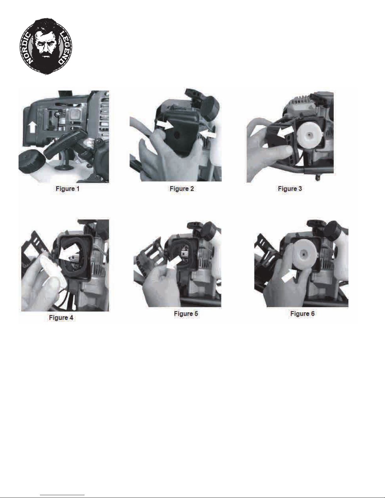
STEPS FOR CLEANING BLOCK STYLE FOAM AIR FILTER
NOTE: SEE PARTS EXPLOSION ON PAGE 16
1. Before removing the air lter cover, move the choke lever to the choke position (See Figure 1)
2. To remove air lter cover, get away the bolt on the cover and squeeze the latch tabs on both sides of the cover (See Figure 2)
3. Once the latch tabs are released, remove air lter cover by rotating the cover away from the engine (See Figure 3)
4. Remove the white plastic cover and the foam lter element (See Figure 4) and replace with anew oiled lter, or clean the
original foam lter with warm water and mild soap by following the previous steps for Cleaning Air Filter. Remember to
thoroughly oil the foam lter with 30 or 40 weight motor oil and squeeze out any excess oil
5. Reinstall the foam lter and white plastic cover, pressing it in place to ensure that the foam is fully seated into its sealed
position (See Figure 5 & 6)
6. Replace the air lter cover so that it fully snaps into place and is secured by the latch tabs. Check that the cover is securely
attached by pulling slightly on the cover. If the cover does not move when pulled, then it is secure
TOLL FREE HELP LINE 1-844-688-0690 10

CARE AND USE MANUAL
MODEL B33Z08 & B33Z10
POWER ICE AUGER
SPARK PLUG
The recommended spark plug is a A5RTC
1. Check spark plug every 50 operating hours
2. Disconnect the spark plug cap and clean any debris from around the spark plug area
3. Remove spark plug and replace if any of the following occur: Pitted Electrodes, Burned Electrodes, Cracked
Porcelain or deposits around electrodes
4. After analysis, seat spark plug and tighten with spark plug wrench
5. If reinstalling original spark plug tighten an additional 1/2 turn
6. If installing a new spark plug, adjust spark plug gap to .028" and tighten additional 1/8 to 1/4 turn
NOTE: Loose spark plug may overheat and damage engine. Over tightened spark plug may damage threads in
the cylinder head
TRANSPORTING YOUR ICE AUGER
1. Never transport engine inside enclosed space or vehicle. Fuel or vapors may ignite causing injury or death
2. If fuel is present in the fuel tank, transport in an open vehicle in an upright position
3. If an enclosed vehicle must be used, remove gas into an approved red fuel container. DO NOT siphon by mouth
4. Run engine to use up the fuel in the carburetor and fuel tank... Always run engine in a well vented area
5. Wipe away any spilled fuel from engine and body of ice auger... allow to dry
LONG TERM STORAGE
If your ice auger will not be ran for more than one month, pre- pare it for long term storage
Steps for Long Term Storage
1. Add fuel stabilizer according to the manufacturer's instructions
2. Run engine for 10-15 minutes to ensure that the stabilizer reaches the carburetor
3. Remove the remainder of the fuel from the gas tank into an approved fuel container
4. Remove auger from powerhead and apply a thin layer of grease to the output shaft
5. Store auger and powerhead (engine) in a vertical position
6. Remove all debris from the auger and powerhead (engine)
7. Attach blade protector to the bottom of auger cutting blade
TOLL FREE HELP LINE 1-844-688-0690 11

ICE POINT REPLACEMENT
1. Remove blade protector and both blades
2. Using a dedicated wrench remove the point
3. With the dedicated wrench, push in the new point
**Note: DO NOT DAMAGE END OF POINT
4. When installing holder in auger, shaft edges of
the holder may shave off
5. Reattach both blades and put blade protector
back on auger blade
CARE AND USE MANUAL
MODEL B33Z08 & B33Z10
POWER ICE AUGER
NORDIC LEGEND TAKES PRIDE IN EACH AND EVERY UNIT WE PRODUCE. WE BUILD QUALITY AND DURABILITY INTO THE
DESIGN OF ALL OUR PRODUCTS. HOWEVER NO AMOUNT OF CAREFUL DESIGN ON OUR PART AND NO AMOUNT OF CAREFUL
MAINTENANCE BY YOU, CAN GUARANTEE A REPAIR FREE LIFE FOR YOUR UNIT. MOST REPAIRS WILL BE MINOR AND EASILY
FIXED BY FOLLOWING THE SUGGESTIONS IN THE TROUBLESHOOTING SECTION OF THE MANUAL. THIS SECTION WILL HELP
YOU LOCATE AND ISOLATE THE CAUSES OF THE COMMON PROBLEMS AND IDENTIFY HOW TO FIX THEM. WE WILL ALWAYS
BE THERE TO ANSWER ANY QUESTIONS YOU MIGHT HAVE OR TO HELP YOU FIND SUITABLE ASSISTANCE.
TO ORDER PARTS OR INQUIRE ABOUT WARRANTY, CALL, WRITE OR EMAIL US AT THE CONTACT INFORMATION BELOW:
TOLL FREE HELP LINE 1-844-688-0690 12
SERVICE INFORMATION
Nordic Legend
PO Box 145
Clayton, WI 54004
844-688-0690
www.nordic-legend.com

CARE AND USE MANUAL
MODEL B33Z08 & B33Z10
POWER ICE AUGER
TROUBLESHOOTING SECTION
PROBLEM
1. Power switch off 1. Flip switch to ON position
2. Spark plug wire disconnected 2. Connect spark plug wire to spark plug
3. Out of fuel 3. Refuel
Engine will not start
Engine runs rough, floods during
operation
Engine is hard to start
Engine misses or lacks power
Engine runs, then quits
Engine revs too high 1. Carburetor out of adjustment
Auger turns at idle
Auger turns, but has no power
Auger jumps 1. Blade damaged 1. Replace with new blade
Auger cuts slowly
4. Spark plug wet, faulty or improperly
gapped
5. Throttle control not held open
6. Fuel line hose not positioned in
bottom of gas tank
1. Dirty air filter 1. Clean or replace air filter
2. Choke partially engaged 2. Turn off choke
3. Carburetor out of adjustment
1. Stale fuel
2. Spark plug wire loose
3. Dirty carburetor
4. Throttle control not held open
1. Clogged gas tank 1. Remove and clean
2. Clogged air filter 2. Clean or replace
3. Carburetor o
4. Spark plug wet, faulty or improperly
gapped
1. Gas cap not venting
2. Plugged fuel filter 2. Clean or replace
3. Carburetor out of adjustment or bad
1. Idle speed too high 1. Adj
2. Broken clutch spring 2. Replace spring
1. Choke
2. Carburetor out of adjustment 2. Consult Service Center
3. Broken transmission 3. Consult Service Center
4. Worn clutch shoes 4. Replace clutch shoes and spring
5. Worn engine lower seat
1. Dull blade
2. Damaged point 2. Replace point
POSSIBLE CAUSE REMEDY/ACTION
4. Clean, replace or gap spark plug
5. Squeeze throttle control when
pulling recoil handle
6. Push fuel line down into fuel in gas tank
1. Drain old fuel and replace with fresh fuel.
Use gas stabilizer additive at end of
season.
2. Make sure spark wire is securely
attached to spark plug
3. Clean carburetor, use gas stabilizer, new
gas can
4. Prime unit 3 more times, squeeze
throttle when pulling recoil handle
ut of adjustment or bad 3. Consult Service Center
4. Clean, replace or gap spark plug
1. Open manual venting gas cap screw all
the way open (counterclockwise)
ust idle speed lower
on 1. Turn off choke after engine is running
1. Buy new blade, or have
sharpened at factory
blade
TOLL FREE HELP LINE 1-844-688-0690
13

CARE AND USE MANUAL
MODEL B33Z08 & B33Z10
POWER ICE AUGER
48
35
34
57
44
33
30
28
31
27
42
43
12
53
50
32
29
39
36
24
49
20
23
25
22
15
14
21
47
40
47
3
13
41
38
37
11
48
TOLL FREE HELP LINE 1-844-688-0690 14
10
54
17
55
56
46
52
18
5
1
2
4
16
45
46
9
8
47
7
6

ENGINE PARTS LIST
KEY
NO.
10 RECOIL CLUTCH 1
11 PLATE, RECOIL 1
12 HANDLE, RECOIL (STANDARD) 1
13 RECOIL ASSEMBLY WITH
14 IGNITION COIL 1
15 SHROUD, ENGINE 1
16
17 GASKET, MUFFLER 1
18 MUFFLER 1
19
20 SPARK PLUG 1
21 COVER, ENGINE SHROUD 1
22 GASKET, INTAKE 1
23 WINDPIPE, INTAKE 33CC 1
24 GASKET, CARBURETOR 1
25 CARBURETOR 1
26
27
28 BASE, INTAKE 1
29 CHOKE LEVER, SIDE MOUNT 1
30 CHOKE COVER 1
31 1
32 1
33
34 AIR FILTER 1
35 COVER, INTAKE 1
36
PART
NO. DESCRIPTION QTY.
B330001
1 FLYWHEEL, MAGNETO 1
B330002
2 NUT, FLANGE M8 1
B330003
3 WASHER, ROTOR 2
4
B330004
5 SPRING, CLUTCH 1
B330005
6 WASHER, SPRING 2
B330006
7 BOLT, SHOULDER 2
B330007
B330008
8 PIN, LOCATING 2
B330009
9 MOUNT RING & SHROUD 1
B330010
B330011
B330012
B330013
B330014
B330015
B330016
B330017
B330018
B330020
B330021
B330022
B330023
B330024
B330025
B330028
B330029
B330030
B330031
B330032
B330033
B330034
B330035
B330036
CLUTCH ROTOR ASSEMBLY 1
STANDARD HANDLE
MUFFLER
PRIMER BULBB330027 1
SCREW,THROTTLE LEVER
PLATE, INTAKE COVER
ADAPTER
COVER, AIR FILTER
DEEPEN HANDLE FOR CARBURETOR
BOLT
CARE AND USE MANUAL
MODEL B33Z08 & B33Z10
POWER ICE AUGER
KEY
NO. PART NO. DESCRIPTION QTY.
37 GAS TANK 1
B330037
38 GAS CAP, MANUAL VENTING 1
B330038
B330039
39
40
B330040
41 GROMMET, 2-HOLE GAS TANK 1
B330041
42 HOSE, PRIMER LINE 1
B330042
43 HOSE, FUEL LINE 1
B330043
44 BOLT 4
B330044
45 NUT, FLANGE M5 2
B330045
46 BOLT W/WASHER M5 X 12MM 1
B330046
47 BOLT W/WASHER PH M5 X 20MM 2
B330047
48 BOLT HH M5 X 16MM 1
B330048
1
2
1
1
1
49 BOLT W/WASHER M5 X 20MM 2
B330049
50 BOLT M5 X 60MM 2
B330050
51
52 KEY, FLYWHEEL 1
B330052
53 FILTER, FUEL 1
B330053
54
B330054
55 1
B330055
56 1
B330056
B330057
57
GASKET
ENGINE WIRE
W/WASHER M5 X 20
GAS TANK RUBBER PLATE
GAS TANK BOARD
RUBBER BUSHING
SWITCH, ROCKER
1
1
2
1
TOLL FREE HELP LINE 1-844-688-0690 15

POWER HEAD & AUGER PARTS EXPLOSION
CARE AND USE MANUAL
MODEL B33Z08 & B33Z10
POWER ICE AUGER
TOLL FREE HELP LINE 1-844-688-0690 16
33
32
35
34
31

POWERHEAD AND AUGER PARTS LIST
CARE AND USE MANUAL
MODEL B33Z08 & B33Z10
POWER ICE AUGER
KEY
NO.
1
2
3 TRANSMISSION COMPLETE 1
4
5
6
7
8
9
10
11
12
13 Y43.05-03
14
15 Y43.05-02
16
17
18
19
20
21
22
PART
NO. DESCRIPTION QTY.
GAS ENGINE, 33CC 1
B33.02A
B33.03
Y43.03
Y43.02 THROTTLE CABLE 1
B33.03-01
Y43.04 CLUTCH DRUM 1
Y43.05-04 GEAR 7T PINION THREADED 1
Y43.05-05
B33.03-02
B33.03.01
Y43.05-08 GEAR CASE BOTTOM 1
Y43.05-07 SHAFT OUTPUT 7/8” 1
BZ08 ICE AUGER 8” 1
BZ09 ICE AUGER 9” 1
BZ10 ICE AUGER 10” 1
HANDLEBAR 1
TRIGGER ASSEMBLY, LONG
THROW
BOLT 10-24 X 1-1/4 PPH 1
BOLT M6 X 16mm 4
GEAR CASE TOP 1
BALL BEARING R12 DOUBLE LIP 3
SNAP RING 2
DOWEL PIN STEEL 1/4” X 1/2” 1
GEAR 48T 3/4” HOLE 1
GASKET 1
BALL BEARING R10 2
GEAR 7T/48T ONE-PIECE
CLUSTER
BOLT 1/4-20 X 1-1/2 SHCS 2
BOLT 1/4-20 X 2 SHCS F-T
W/PATCH
KEY
NO.
1
1
4
PART
NO.
23
24 BD08 ICE BLADES 8” COMPLETE
BD09
BD10
25
26 NUT-NYLOC 5MM X 0.8 4
27 BT08 BLADE PROTECTOR KIT 8” 1
BT09
BZ08.00-04 RUBBER STRAP 1
28
B33.00-02
29
30 AXLE SLEEVE
B33.03-03
BZ08.00-03
31 1
32
33
34
35
DESCRIPTION
BOLT 3/8-16 X 1-1/4 SHCS
SET OF 2 BLADES
ICE BLADES 9”
COMPLETE SET, SET OF 2
BLADES
ICE BLADES 10”
COMPLETE SET OF 2 BLADES
BOLT 5MM X 0.8 X 16mm HH
BLADE PROTECTOR KIT 9” & 10”
ADAPTER RING
POINT
BOLT 10-24 X 1-1/4 HH STAINLESS
NUT 10-24 HEX NYLOC
ICE POINT REPL
HOLDER, POINT
ACEMENT ASSEMBLY
QTY.
1
1
1
1
4
1
1
1
1
1
1
1
TOLL FREE HELP LINE 1-844-688-0690 17

CARE AND USE MANUAL
MODEL B33Z08 & B33Z10
POWER ICE AUGER
WARRANTY
Nordic Legend warrants this product and all parts thereof to be FREE FROM DEFECTIVE MATERIALS AND WORKMANSHIP from
the date of original purchase for the period shown below ONLY TO THE ORIGINAL END-USER PURCHASER. Any Commercial use
or application of this product is warranted for only 90 days. Failure to register your unit either by mail or online within 30 days of
your purchase could void your warranty.
Model Serial Number Auger Engine
B33Z08/10 1 YR 2 YR
PRODUCT 1 YEAR LIMITED WARRANTY:
Nordic Legend warrants the Nordic Legend Ice Auger to be FREE FROM DEFECTIVE MATERIALS AND WORKMANSHIP from the
date of the original purchase for a period of 1 Year. Any Commercial use or application of this product is warranted for only 90
days. Failure to register your unit either by mail or online within 30 days of your purchase could void your warranty
ENGINE 2 YEAR LIMITED WARRANTY:
Nordic Legend warrants the engine used in its Ice Auger to be FREE FROM DEFECTIVE MATERIALS AND WORKMANSHIP from
the date of original purchase for a period of 2 Years. Any Commercial use or application of this product is warranted for only 90
days. Failure to register your unit either by mail or online within 30 days of your purchase could void your warranty.
You are responsible for the proper use and maintenance of your Nordic Legend Auger and its engine. Nordic Legend suggests
that you maintain any receipts and maintenance records of your unit. Any misuse of the unit could result in denial of repairs that
could be covered under Nordic Legend’s Warranty Normal maintenance and scheduled inspection of all Nordic Legend Ice
Auger parts, including emissions related parts is the total responsibility of the owner.
TOLL FREE HELP LINE 1-844-688-0690 18

CARE AND USE MANUAL
MODEL B33Z08 & B33Z10
POWER ICE AUGER
NORDIC LEGEND ICE AUGER LIMITED WARRANTY
Nordic Legend reserves the right to amend any specications at any time without notice. This is the only warranty that is valid
and is our standard written warranty. This is the only warranty that is applicable to our product and we make no other warranty,
either expressed or implied. The warranty is offered only to the original retail purchaser. Your Retail Sales Receipt is your Proof
of Purchase and must be presented at the time any claim is made under the warranty provisions of this warranty.
This warranty covers commercial, industrial use only for a period of 90 days from the original date of purchase. This warranty
will not apply to any parts that are damaged because of normal wear and tear or to any parts that fail or become damaged as a
result of misuse, accidents, lack of proper maintenance, tampering or alteration of any parts.
The warranty applies only to Nordic Legend which have not been subjected to misuse, accidents, alterations, careless use,
improper use of fuels or oils, or improper repairs by non-authorized Service Centers.
Transportation, handling or subsidiary associated with warranty repairs are not subject to reimbursement by Nordic Legend or
their Approved Service Centers. Nordic Legend is not liable for any other damages at all that may become associated with the
use of this product. These include indirect, incidental or consequential damages. This warranty provides the original purchaser
with specic rights.
ALWAYS CONTACT NORDIC LEGEND’S AUTHORIZED SERVICE CENTER FOR A
RETURN AUTHORIZATION NUMBER BEFORE RETURNING ANY PRODUCT
WHAT WE WILL DO:
If this product is found to be defective within the warranty period, Nordic Legend will repair or replace defective parts with new
or rebuilt equivalents at no charge to the original owner. Such repair and replacement services shall be rendered by Nordic
Legend's Authorized Service Center during normal business hours. Parts used for replacement are warranted only for the
remainder of the Warranty Period from the original purchase
WHAT YOU MUST DO FOR WARRANTY SERVICE:
Box the product carefully, preferably in the original carton and ship PREPAID to Nordic Legend's Authorized Service Center
It is recommended that you insure the product against loss or damage. Please be sure to include a copy of your sales receipt
to substantiate warranty (if applicable) and a note detailing the problem
If you have any questions or concerns, please contact Nordic Legend’s Authorized Service Center
by calling our Toll Free Number listed below
1-844-688-0690
TOLL FREE HELP LINE 1-844-688-0690 19

 Loading...