

Page 1
Common Maker
Installation Instructions
Overview
● The Common Maker provides a common connection
‘C’ for Wi-Fi and powered thermostats.
● A common connection allows the thermostat to
operate without batteries or “power stealing” circuits.
● The Common Maker is compatible with all 24VAC
heating and cooling systems.
Electrical Safety
● This product should only be installed by a qualified
technician.
● Requires a Class 2 transformer providing 23-28VAC.
● The total connected load must not exceed 2 amps.
● The connected load cannot operate at more than
30VAC (not designed for direct connection to 120VAC
equipment).
● To avoid risk of electrical shock or equipment damage,
disconnect power before beginning installation.
Sender Installation
The Sender is the smaller component and has purple,
white, and black wires. It is installed inside the wall behind
the thermostat.
1. Remove the thermostat from its base.
2. The thermostat base will have wires running into the
wall through a small hole. If this hole is not big enough
to fit the Sender, enlarge the hole.
3. Find the wiring diagram for your system (pages 2-4)
and connect the wires accordingly.
4. Place the Sender in the wall. It will hang by its wires
and does not require any mounting.
5. Place the thermostat back on its base.
Note: The Sender will produce a small amount of heat
while operating. Keep the Sender wires as long as possible
to maximize the distance between the Sender and
thermostat. Do not install the Sender in insulated walls.
Receiver Installation
The Receiver is the larger component and has purple,
white, black, and red wires. It is installed near the furnace,
boiler, air handler, zone valve, or zone controller. It should
be placed in the equipment cabinet or a location without
exposure to liquids or high temperatures.
Follow the relevant wiring diagram for your system (pages
2-4) and connect the wires accordingly. Additional wiring
diagrams may be found at www.fast-stat.com.
Troubleshooting
1. Measure the transformer voltage to ensure it is
between 23-28VAC. If it is outside this range the
Common Maker may not work as intended.
2. If the thermostat has power but the Common Maker
will not activate the equipment, try reversing the wires
in the thermostat cable.
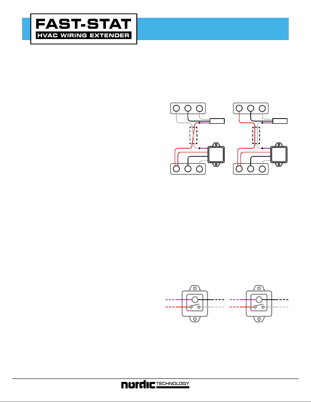
Incorrect
Thermostat
R C
Thermostat
Cable
R C
Furnace
W
W
Common
Maker
Thermostat
Cable
3. At the thermostat base, place a jumper wire between
the ‘R’ and ‘W’ terminals. This should cause the heating
system to start. If the heating system does not start,
the thermostat cable or Common Maker may be faulty.
4. Disconnect the Sender and bring it to the location of
the Receiver. While keeping the Receiver connected
to the equipment, connect the Sender and Receiver
purple wires together. Then apply 24VAC to the
Sender white wire. The relay in the Receiver should
energize. If the relay does not energize, the Common
Maker may be faulty.
Internal Wiring
When the Sender has 24VAC applied to its white wire, it
will energize the relay in the Receiver, and complete the
circuit between the Receiver red and white wires. In most
installations, this will connect the ‘R’ and ‘W’ terminals on
the furnace.
Standard
To Sender
R
RELAY
To Sender
C
W
T
Correct
Thermostat
R C
R C
Furnace
Dry-Contact
RELAY
W
W
Common
Maker
C
T
Testing
After the Common Maker has been installed, check to see
if it is functioning properly by following these steps:
1. Check that the thermostat will power on.
2. Use the thermostat to turn on the heating system, and
ensure that the heating system turns on.
3. Use the thermostat to turn off the heating system, and
The Common Maker also supports dry-contact switching.
In this configuration, the two ‘T’ terminals are electrically
isolated from the thermostat transformer.
Contact Us
For installation assistance, our technical support line can
be reached at 1-800-775-4750, 9am-5pm PST, or emailed
at [email protected]
ensure that the heating system turns off.
Page 1 of 4 www.fast-stat.com
Page 2
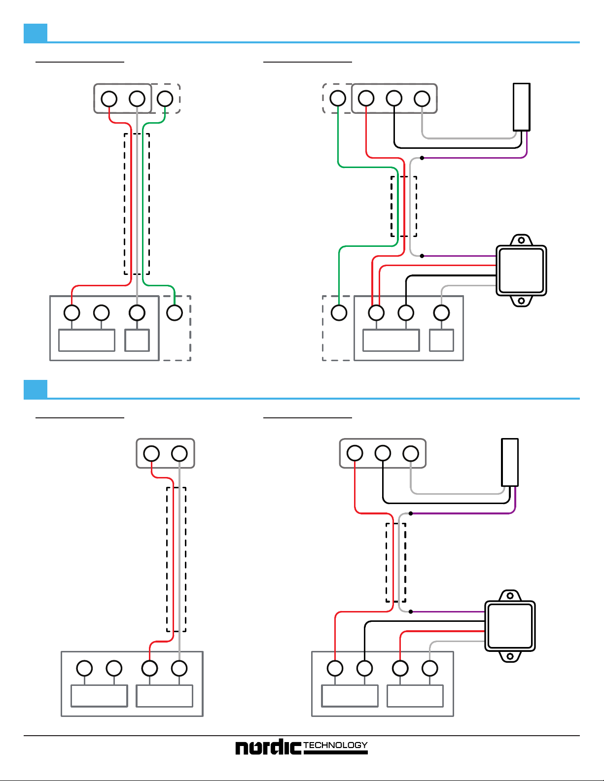
Typical Installation for Furnaces and BoilersA
Before
24V Transformer
Thermostat
R W
Thermostat
Cable
R C
W
Heat
After
Thermostat
R C
G
G
W
If your system has additional
wires (G, H, etc), they can
remain connected directly to
Thermostat
Cable
the equipment.
Purple
Red
Black
White
G
G W
R C
24V Transformer
Heat
Sender
White
Black
Purple
Receiver
Common
Maker
Dry Contact Switching with Internal TransformerB
Before
Furnace / Boiler
Thermostat
Thermostat
Cable
Furnace / Boiler
After
Thermostat
R
W
R C
W
Thermostat
Cable
Purple
Black
Red
White
Sender
White
Black
Purple
Receiver
Common
Maker
R C
24V Transformer
T
Heat
T
24V Transformer
TR C
T
Heat
ControllerController
Page 2 of 4 www.fast-stat.com
Page 3
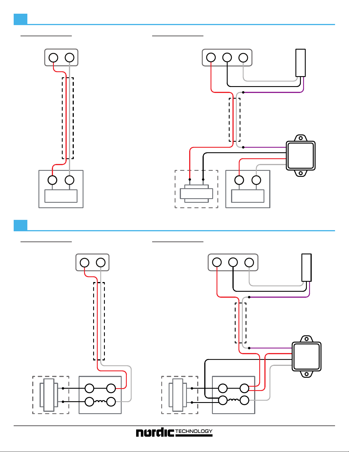
Dry Contact Switching with External TransformerC
Before
Thermostat
Cable
Thermostat
R W
T
T
Control
After
If a 24V transformer is not
accessible, a new transformer will
have to be installed at the location
of the Common Maker Receiver.
Thermostat
Cable
24V Transformer
Thermostat
R C
W
T
Control
Sender
White
Black
Purple
Receiver
Purple
Black
Red
White
Common
Maker
T
Directly Connected Gas ValveD
Before
Equipment
Thermostat
Cable
Thermostat
R W
After
Thermostat
R C
Thermostat
Cable
EquipmentExternal Transformer
Sender
W
White
Black
Purple
Receiver
Purple
Red
Black
White
Common
Maker
24V Transformer
THTR
TR TH
External Transformer
Page 3 of 4 www.fast-stat.com
Gas Valve
External Transformer
24V Transformer
THTR
TR TH
Gas Valve
Page 4
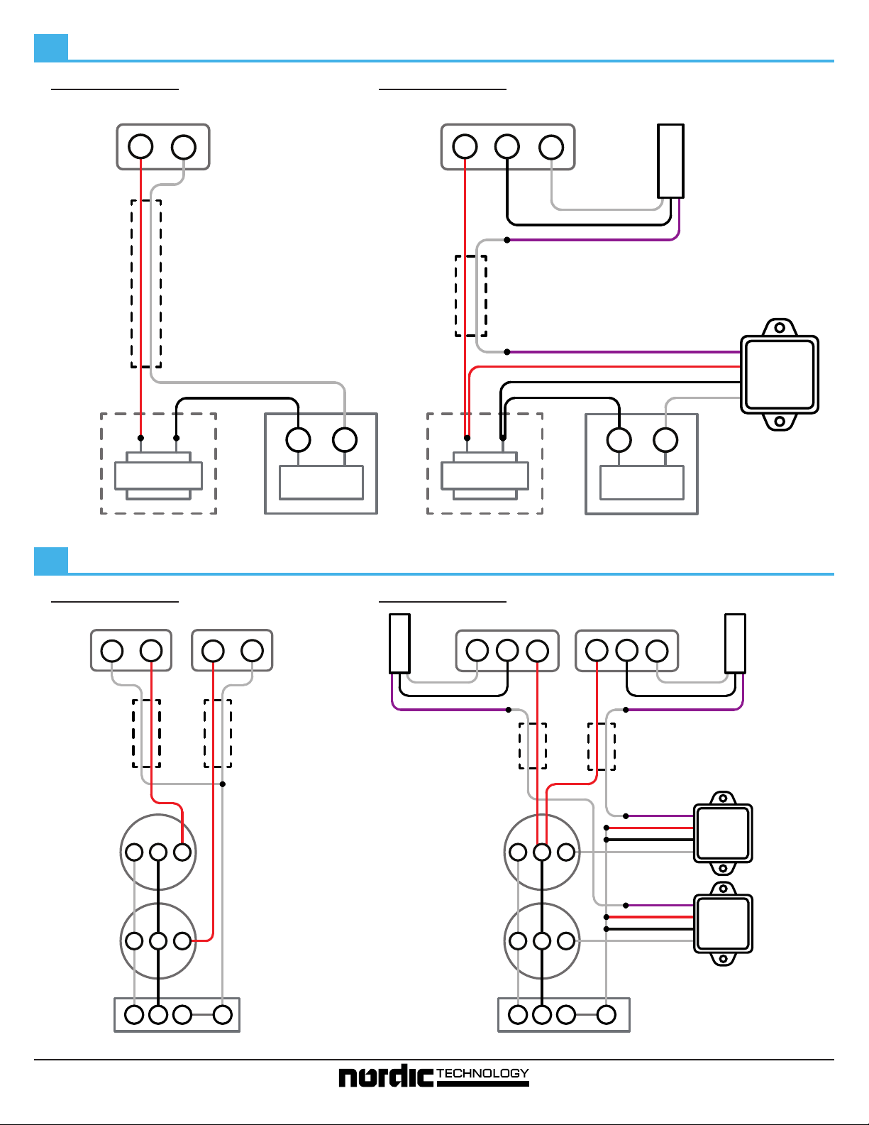
Externally Powered EquipmentE
Before
Thermostat
Cable
Thermostat
R
W
24V Transformer
Control
After
Thermostat
TT
Cable
Thermostat
R
C
24V Transformer
W
White
Black
Purple
Control
Sender
TT
Purple
Red
Black
White
Receiver
Common
Maker
External Transformer
Zone Valve with Z-TV-W Aquastat (Varies by manufacturer - see www.fast-stat.com for additional wiring diagrams)F
Before
Thermostat Thermostat
W R R W
Thermostat
Cable
Zone Valve
Zone Valve
3 2 1
3 2 1
Equipment
Thermostat
Cable
Sender
External Transformer
After
White
Black
Purple
Thermostat
Cable
Zone Valve
Zone Valve
Thermostat
W C
3 2 1
3 2 1
Equipment
Thermostat
C
R
R
W
White
Black
Purple
Thermostat
Cable
Purple
Red
Red
Common
Maker
Common
Maker
Black
White
Purple
Black
White
Sender
Receiver
Receiver
TV
T
W
Z
Aquastat
Page 4 of 4 www.fast-stat.com
TV
T
Z
Aquastat
W
 Loading...