

NORDAC SK 400E installation Guide
NORDAC SK400E Manual Safety Instructions
Operation Instructions
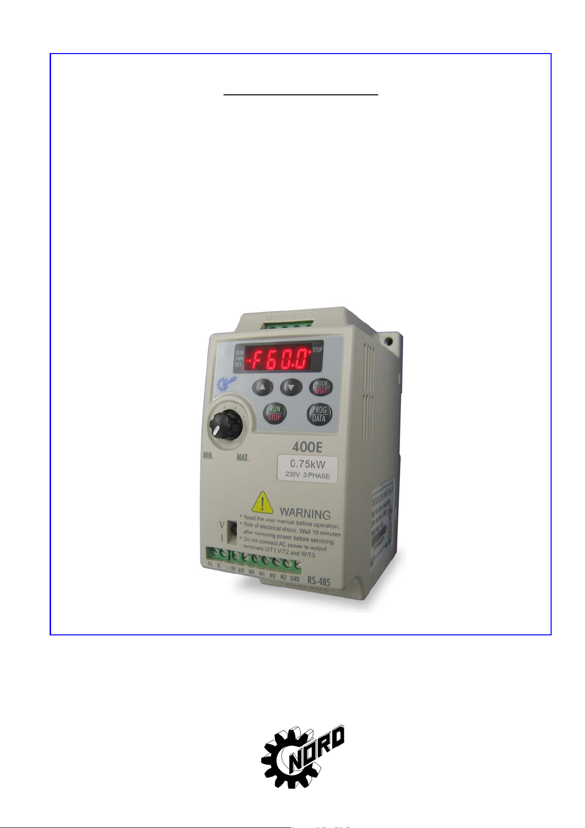
NORDAC SK 400E
Frequency Inverter
SK 400E-200-111-B / SK 400E-400-111-B
(0.4kW / 0.7kW, 1~ 115V)
SK 400E-200-123-B ... SK 400E-151-323-B
(0.2kW … 1.5kW, 1/3~ 230V, 3~ 230V)
BU 0400 DE
November 2005
A1
Getriebebau NORD
GmbH & Co. KG
NORDAC SK400E Manual Safety Instructions
NORDAC SK 400E
Frequency Inverter
Safety and operating instructions
for variable speed drives
Thank you for choosing a NORDAC SK400E series AC drive. The SK400E series is manufactured
using high-quality components, material and incorporating the latest microprocessor technology
available.
This manual will help with installation, parameter setting, troubleshooting and daily maintenance
of the AC motor drive. To guarantee safe operation of the equipment, read the following safety
guidelines before connecting power to the AC motor drive. Keep this operating manual handy and
distribute to all users for reference.
Important Notes:
DANGER! AC input power must be disconnected before any maintenance. Do not connect or
disconnect wires while power is applied to the circuit. Only qualified technicians should
perform maintenance on the SK400E.
CAUTION! There are highly sensitive MOS components on the printed circuit boards. These
components are especially sensitive to static electricity. To avoid damaging these
components, do not touch the circu i t boards with metal objects or your bare hands.
DANGER! A charge may still remain in the DC-link capacitor with hazardous voltages even
after the power has been turned off. To avoid personal injury, do not remove the cover of the
AC drive until all “DISPLAY LED” lights on the digital keypad are off. Please note that there
are live components exposed when the AC drive is open. Be careful to not touch these live
parts.
CAUTION! Ground the SK400E using the ground terminal. The grounding method must
comply with the laws of the country where the AC drive is to be installed.
DANGER! The AC drive may be destroyed beyond repair if power is misapplied to the
input/output terminals. Never connect the AC drive output terminals U/T1, V/T2, W/T3
directly to the AC main circuit power supply.
A1
NORDAC SK400E Manual
Chapter 1 Receiving and Inspection
This SK400E frequency inverter has gone through rigorous quality control tests at the factory
before shipment. Since many things may happen during shi pping, please check for the following
after receiving the frequency inverter.
• Inspect the unit to ensure it was not damaged during shipment.
• Make sure that the part number indicated on the nameplate corresponds with the part number
of your order.
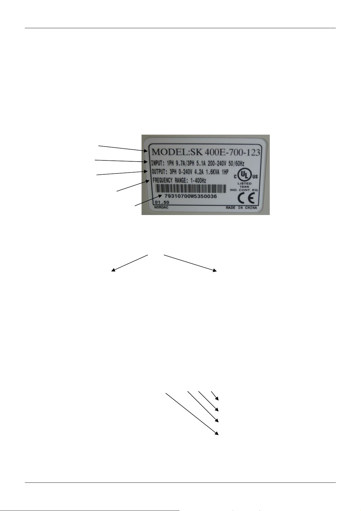
Nameplate Information: Example of 0,4kW 1~/3~ 230V
Inverter type
Input spec.
Output spec.
Output freq, range
Bar code with serial code
Model Explanation:
SK 400E-700-123
Applicable motor capacity: Input voltage:
200: 0.2kW /
400: 0.4kW /
1
/4 hp 111: 115V 1 phase
1
/3 hp 123: 230V 1 or 3 phase
700: 0.7kW / 1 hp 323: 230V 3 phase (only)
151: 1.5kW / 2hp
Series Number Explanation:
79310700 W 5 35 0036
Internal production number (0036)
Production week (35 Æ week 35)
Production year (5 Æ 2005)
Nord part number (79310700)
If there is any nameplate information not corresponding to your purchase order or any problem,
please contact your distributor.
1
NORDAC SK400E Manual
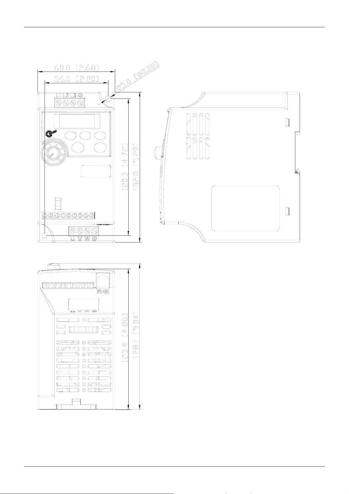
Dimension
MIN. MAX.
V
I
400E
RS-485
2
UNIT: mm(inch)
NORDAC SK400E Manual
←
Chapter 2 Wiring
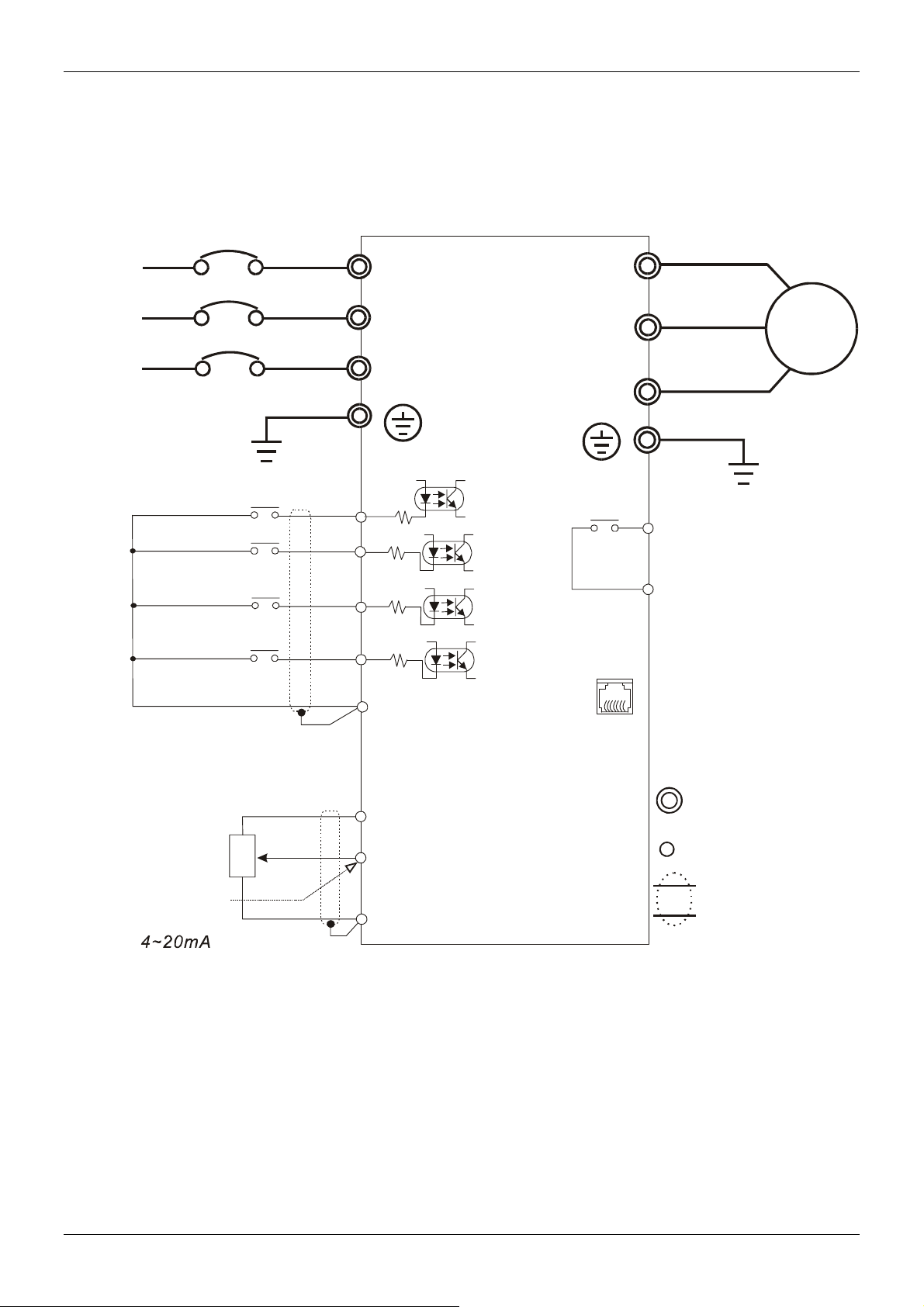
Basic Wiring Diagram
Users must connect wiring according to the circuit diagram shown below. Please follow all
applicable local wiring codes, when wiring the SK400E.
Main Circuit Power
MCCB
R/L1
S/L2
T/L3
Factory default settings
Forward/Stop
Reverse/Stop
Reset
Multi-s tep 1
Common Signal
Power supply for Potentiometer
+10V 10mA(MAX)
Master Freq. setting
Anal og voltage
010VDC
~
VR 3K 5K
:~Ω
Analog current
VR
3
2
1
M0
M1
M2
M3
GND
R/L1
S/L2
T/L3
4.7K
Ω
4.7K
Ω
4.7K
Ω
4.7K
Ω
+10V
AVI
GND
+18V
+18V
+18V
+18V
U/T1
V/T2
W/T3
RA
RC
RJ-11
61
RS-485
Commun icat ion
port
IM
3~
Motor
Multi-function indication
output contacts
120VAC/28VDC 3A
Factory default:
Fault Indication
1:+EV
2:GND
3:SG4:SG+
Main ci rcuit (power)
terminals
Control circuit terminals
Shielded leads
NOTE: Do not plug in a Modem or telephone line to the RS-485 communication port,
permanent damage may result. Terminals 1 & 2 are the power source for the
optional copy keypad and should not be use d while using RS-485
communication.
*If the AC Drive model is SK 400E-200-111/123, SK 400E-400-111/123,
SK 400E-700-123, please use power terminals R/L1 and S/L2.
*If the AC Drive model is SK 400E-200-123, SK 4 00E-400-123,SK 400E-700-123 ,
3 phase power may be used on R/L1, S/L2, T/L3.
*If the AC Drive model is SK 400 E-151-3 23, single phase power is not allowe d.
3
NORDAC SK400E Manual
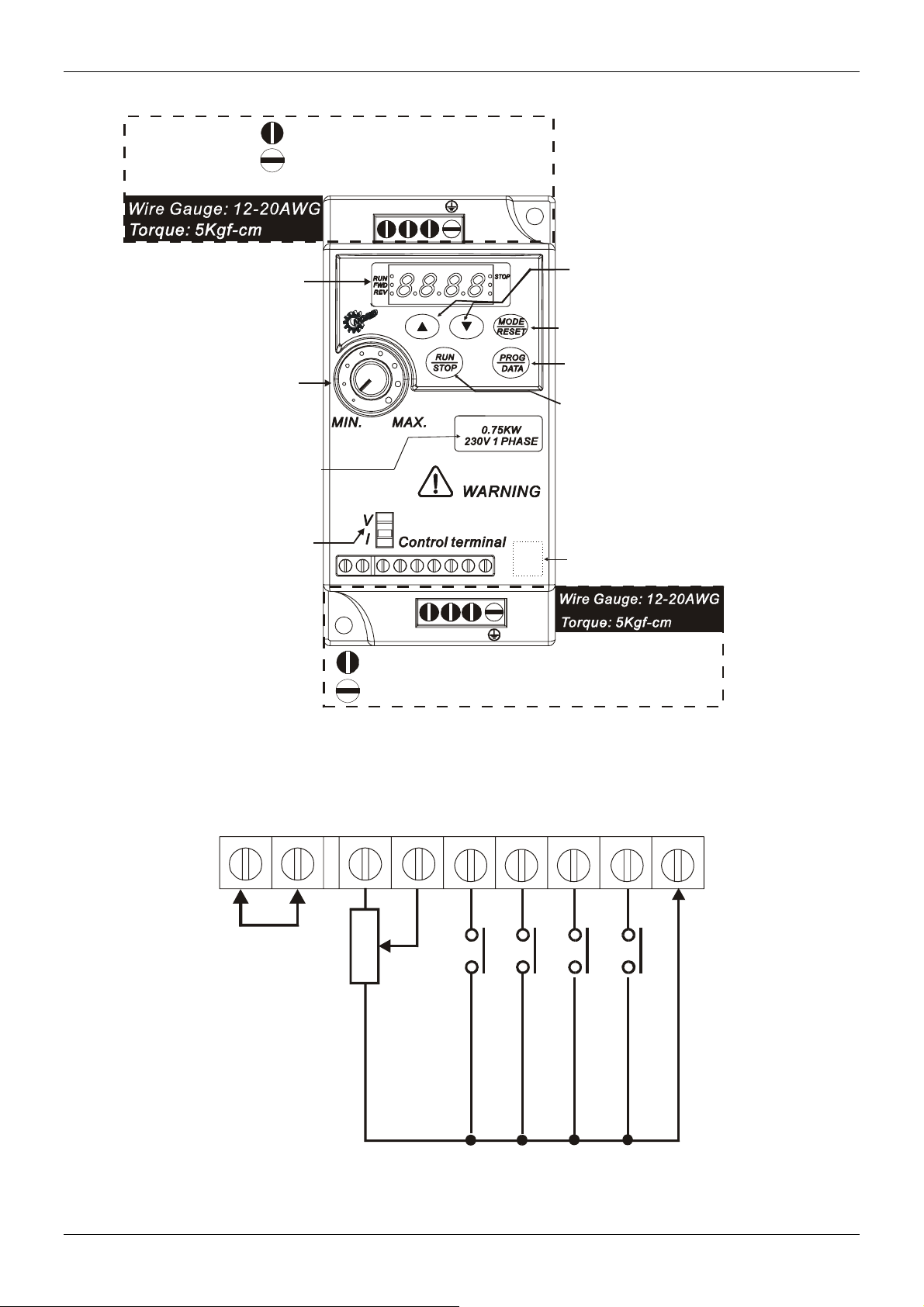
Main circuit wiring
AC line input terminals
grounding
Single phase models input from R/L1, S/L2
R/L1 S/L2
T/L3
LED display
UP/DOWN
Functio n
Display key
Data
Frequency
Confirmation key
setting knob
400E
RUN/STOP
Motor capacity
and input power
The signal selection
for AVI to input
DC0~+10V
or 4~20 mA
U/T1 V/T2 W/T3
RS485
communication
port
Motor connections U/T1, V/T2, W/T3
Grounding
Control circuit wiring
Wire Gauge:22-24AWG
Torque: 4Kgf-cm
RA RC +10V
M
o
(
1
u
u
2
Relay
t
l
p
0
t
i
u
V
f
t
A
u
c
C
n
o
c
/
n
D
t
t
i
a
o
C
c
n
2
t
i
8
n
V
d
i
3
c
A
a
)
t
i
o
n
AVI
P
o
w
e
r
f
o
r
s
p
e
e
d
s
e
t
t
i
n
g
Wiring Notes: PLEASE READ PRIOR TO INSTALLATION.
M0 M1
A
f
r
n
e
a
q
l
u
o
e
g
n
V
c
o
y
l
c
t
a
o
g
m
e
m
,
c
a
u
n
r
d
r
e
n
t
M
u
l
t
i
f
u
n
c
t
i
o
n
a
s
s
i
s
t
a
n
t
t
e
r
m
i
n
a
l
M
u
l
t
i
f
u
n
c
t
i
o
n
i
n
p
u
t
s
e
l
e
c
t
i
o
n
1
M2 M3
M
u
l
t
i
f
u
n
c
t
i
o
n
i
n
p
u
t
s
e
l
e
c
t
i
o
n
2
GND
M
C
o
u
m
l
t
i
m
f
u
o
n
n
c
s
t
i
i
g
o
n
n
a
i
n
l
p
u
t
s
e
l
e
c
t
i
o
n
3
4
 Loading...