

Page 1
USER MANUAL
Software Version 1.0X
Part No. 50303 Copyright Clavia DMI AB 2007
Print Edition 1.00
Page 2
The lightning ash with the arrowhead symbol within an
equilateral triangle is intended to alert the user to the
presence of uninsulated voltage within the products
enclosure that may be of sufcient magnitude to constitute
a risk of electric shock to persons.
Le symbole éclair avec le point de èche à l´intérieur d´un triangle
équilatéral est utilisé pour alerter l´utilisateur de la presence à
l´intérieur du coffret de ”voltage dangereux” non isolé d´ampleur
sufsante pour constituer un risque d`éléctrocution.
The exclamation mark within an equilateral triangle is
intended to alert the user to the presence of important
operating and maintenance (servicing) instructions in the
literature accompanying the product.
Le point d´exclamation à l´intérieur d´un triangle équilatéral est
employé pour alerter l´utilisateur de la présence d´instructions
importantes pour le fonctionnement et l´entretien (service) dans le
livret d´instructions accompagnant l´appareil.
Instructions pertaining to a risk of re, electric shock or injury to persons.
IMPORTANT SAFETY INSTRUCTIONS
SAVE THESE INSTRUCTIONS
CAUTION AVIS
RISK OF ELECTRIC SHOCK
DO NOT OPE
N
RISQUE DE SHOCK ELECTRIQUE
NE PAS OUVRIR
CAUTION: TO REDUCE THE RISK OF ELECTRIC
SHOCK DO NOT REMOVE COVER (OR BACK).
NO USER SERVICEABLE PARTS INSIDE.
REFER SERVICING TO QUALIFIED PERSONNEL.
ATTENTION :POUR EVITER LES RISQUES DE CHOC
ELECTRIQUE, NE PAS ENLEVER LE COUVERCLE.
AUCUN ENTRETIEN DE PIECES INTERIEURES PAR L´USAGER.
CONFIER L´ENTRETIEN AU PERSONNEL QUALIFE.
AVIS: POUR EVITER LES RISQUES D´INCIDENTE OU
D´ELECTROCUTION, N´EXPOSEZ PAS CET ARTICLE A LA PLUIE
OU L´HUMIDITET.
Warning - When using electric products, basic
precautions should always be followed, including
the following:
1. Read all the instructions and observe the graphic
symbols above before using the product.
2. Do not use this product near water - for example
near a bathtub, washbowl, kitchen sink, in a wet
basement, near or in a swimming pool, a swamp or
the like.
3. This product should be used only with a cart or a
stand that is recommended by the manufacturer.
4. This product, either alone or in combination with an
amplier and headphones or speakers may be
perfectly capable of producing sound levels that
could cause permanent hearing loss. Do not
operate for a long period of time at a high volume
level or at a level that is uncomfortable. If you
experience any hearing loss or ringing in the ears,
you should consult an audiologist.
5. The product should be located so that its location
or position does not interfere with or obstruct its
normal ow of ventilation.
6. The product should be located away from heat
sources such as radiators, heat registers or other
products that produce heat.
7. The product should be connected to a power
supply only of the type described in these operation instructions or as marked on the product.
8. The power supply cord of the
product should be unplugged
from the outlet when the product is left unused for a long
period of time.
9. Care should be taken so that objects do not fall, or liquids
are not spilled into the enclosure through openings.
10. The product should be serviced by qualied service personnel when:
A. The power supply cord has been damaged; or
B. Objects have fallen or liquids have been spilled onto the
product; or
C. The product has been exposed to rain; or
D. The product does not appear to operate normally or
exhibits a marked change in performance; or
E. The product has been dropped or the enclosure has
been damaged.
11. Do not attempt to service the product beyond those means
described in this operating manual. All other servicing
should be referred to qualied service personnel.
12. To completely disconnect the apparatus from the mains,
remove the mains plug.
13. Ensure possible protective earting connections of other
equipment when the apparatus is connected to multimedia
systems.
13. Where the Mains plug is used as the disconnect device, the
disconnect device shall remain readily operable.
Trademarks: The Nord logo is registred trademark of Clavia DMI AB. All other trademarks mentioned in this publication are the properties of their respective holders.
Specications and appearances are subject to change without notice.
Copyright by Clavia DMI AB, 2007
Page 3

| 3
Contents
1. Introduction 4
Thank you! . . . . . . . . . . 4
Development story . . . . . . . 4
Features . . . . . . . . . . . . 4
Synthesizer . . . . . . . . . . 4
Eects . . . . . . . . . . . . . 5
Programs . . . . . . . . . . . 5
Samples . . . . . . . . . . . . 5
Control & connections . . . . . . 5
More samples . . . . . . . . . 5
About this manual . . . . . . . 5
2. Overview 6
The Front panel . . . . . . . . 6
Program Section . . . . . . . . 6
Synth Section . . . . . . . . . 6
Eect Section . . . . . . . . . 6
Keyboard Section . . . . . . . . 7
LCD Window . . . . . . . . . . 7
System Menu. . . . . . . . . . 7
MIDI Menu . . . . . . . . . . . 7
About knobs . . . . . . . . . . 7
MASTER LEVEL knob . . . . 7
LCD-dial . . . . . . . . . . . . 7
LED-dials . . . . . . . . . . . 7
Potentiometer knobs . . . . . . 7
About buttons . . . . . . . . . 8
On/o buttons . . . . . . . . . 8
SHIFT button . . . . . . . . . 8
PANIC button . . . . . . . . 8
Slot buttons . . . . . . . . . . 8
OCTAVE SHIFT buttons . . . 8
CHORD button . . . . . . . 8
STORE button . . . . . . . . 8
PROGRAM buttons . . . . . 8
3. Connections 9
Audio Connections . . . . . . . 9
LEFT OUT and RIGHT OUT 9
Headphones . . . . . . . . . . 9
MIDI connections . . . . . . . . 9
MIDI OUT . . . . . . . . 9
MIDI IN . . . . . . . . . 9
USB Connection . . . . . . . . 9
Pedal Connections . . . . . . . 9
SUSTAIN pedal . . . . . . . 9
CONTROL pedal . . . . . . 9
4. The Keyboard Section 10
Panel & Keyboard Focus SLOT A
& SLOT B buttons) . . . . . 10
OCTAVE SHIFT buttons . . 10
CHORD button . . . . . . 11
Modulation wheel . . . . . . 11
Pitch stick . . . . . . . . . . 11
5. The Eect Section 12
Delay . . . . . . . . . . . . .12
TEMPO LED . . . . . . . . 12
AMOUNT knob . . . . . . 12
TEMPO knob. . . . . . . . 12
FEEDBACK button. . . . . 12
STEREO button . . . . . . 13
TAP TEMPO button . . . . 13
Tube amp . . . . . . . . . . .13
DRIVE knob . . . . . . . . 13
Reverb . . . . . . . . . . . . 13
REVERB button. . . . . . . 13
DRY/WET knob . . . . . . 13
6. The Program section 14
What is a Program?. . . . . . . 14
Sorting Programs . . . . . . . 14
Loading a Program . . . . . . 15
Editing a Program. . . . . . . 15
Storing a Program . . . . . . 15
7. The Synth Section 16
MONO MODE . . . . . 16
Selector button . . . . . . . . 16
GLIDE knob . . . . . . . . 16
VIBRATO . . . . . . . . 16
LFO (LFO1 & LFO2) . . . . .16
RATE knob . . . . . . . . . 16
Waveform selector . . . . . . 17
LFO Destination selector . . . . 17
AMOUNT knob . . . . . . 17
POLY mode. . . . . . . . . 17
SINGLE mode . . . . . . . 17
Modulation Envelope (MOD
ENV). . . . . . . . . . . . .17
AT TACK knob . . . . . . . 17
DEC/REL knob. . . . . . . 17
AR button (SHIFT + Dest Sel) 17
AMOUNT knob . . . . . . 17
Destination selector button . . 19
Oscillator (OSC1 & OSC2) . . 19
Oscillator Waveform selector . . 19
Shape (SHAPE1 & SHAPE2/
DEC knob) . . . . . . . . . 19
SEMI TONES knob . . . . 19
FINE TUNE knob . . . . . 19
Oscillator Modulation (OSC
MOD) . . . . . . . . . . . .19
AMOUNT knob . . . . . . 22
TYPE button . . . . . . . . 22
Oscillator mix (OSC MIX) . . .22
MIX knob . . . . . . . . . . 22
Oscillator Sync (SYNC) . . . . 22
Amp. Envelope (AMP ENV) . . 23
AT TACK knob . . . . . . . 23
DECAY knob . . . . . . . . 23
SUSTAIN knob. . . . . . . 23
RELEASE knob . . . . . . . 23
Filter . . . . . . . . . . . . .23
TYPE button . . . . . . . . 23
Filter Frequency FREQ knob) 23
Filter Resonance (RES knob) 23
KB Tracking (KB TRACK) . . 23
Filter Slope (SLOPE button) 25
VELOCITY button . . . . . 25
Filter Envelope . . . . . . . . .25
Env. Amount ENV AMT) . . 25
AT TACK knob . . . . . . . 25
DECAY knob . . . . . . . . 25
SUSTAIN knob. . . . . . . 26
RELEASE knob . . . . . . . 26
OUTPUT . . . . . . . . 26
LEVEL knob . . . . . . . . 26
Equalizer (EQ) . . . . . . . .26
TREBLE knob . . . . . . . . 26
BASS knob . . . . . . . . . 26
CHORUS . . . . . . . . 26
CHORUS button . . . . . . 26
8. The Morph function 27
About Morphing . . . . . . . .27
Morph Sources . . . . . . . . .27
Morph Destinations . . . . . .28
Setting up a morph. . . . . . . 28
Clearing Morphs . . . . . . . .28
Morph Mode . . . . . . . . . .28
Morph Examples . . . . . . . . 28
Use the MODULATION
WHEEL to cross-fade between
two sounds . . . . . . . . . 28
9. MIDI 29
Basic MIDI operation . . . . . . 29
MIDI Menu . . . . . . . . . .29
MIDI implementation . . . . . .30
MIDI implementation chart . . 30
10. System settings 31
System Menu . . . . . . . . . 31
11. NW Manager 32
What is the Nord Wave Manager? 32
Non-destructive editing . . . . 32
System Requirements . . . . . 32
Getting Started . . . . . . . .33
Project, sample memory . . . 33
WYDIWUH . . . . . . . . . . 33
Working oine . . . . . . . . 33
Sample, Zone . . . . . . . . 33
Sample Instruments, Program 33
Sample editing, loop markers,
crossfade . . . . . . . . . . 33
Generate, upload, download . . 33
Librarian . . . . . . . . . . 33
Installation . . . . . . . . . . 34
Installation of the USB driver . . 34
Installation of the Nord Wave
Manager, Windows PC. . . . . 34
Installation of the Nord Wave
Manager, Mac OSX . . . . . . 34
The Quick Tours . . . . . . . .34
First Light . . . . . . . . . . 34
Download to the Nord Wave . . 34
Upload from the Nord Wave . . 35
Create a new Sample Instrument 35
Audio les with ind. samples . . 36
Single Sample Assign . . . . . 36
Editing . . . . . . . . . . . 37
Looping . . . . . . . . . . . 37
Generate a Sample Instrument 38
Program management . . . . 38
Backup the original samples . . 39
NW Manager File Reference . . . 40
File Menu . . . . . . . . . . 40
Instrument Menu . . . . . . . 40
Settings Menu . . . . . . . . 41
Backup Menu. . . . . . . . . 41
Help Menu . . . . . . . . . . 41
NW Manager Tab Reference . . . 41
Common area . . . . . . . . 41
Audio File/Assign Tab . . . . . 42
Sample Loop/Stop Tab. . . . . 44
Sample Start Tab . . . . . . . 46
Instrument Tab . . . . . . . . 46
Nord Wave tab . . . . . . . . 48
12. Appendix 51
Page 4

4 | Nord Wave User Manual OS V1.00
Introduction
1.
Thank you!
First we would like to thank you for purchasing the
Nord Wave. We hope you will nd it to be everything you
have wished for and that you will have many hours of great
fun with your new instrument.
Development story
The Nord Wave is built on a legacy of making virtual analog
synthesizers for more than 15 years. Virtual means “not
physically existing as such but made by software to appear
to do so” , so the nord synthesizers are very digital, but
behaves, feels and sounds like an analog synthesizer.
Surely today, you can nd a lot of digital instruments in
both hardware and software that attempts to sound like an
analog synthesizer. But for the spot-on feel, response and
sound most of them end up quite far from the spot.
To us, details are everything - and an intuative and fast to
use user-interface is just as important as the sound. We are
musicians ourselves, and know by experience how frustrating it can be to have to wade through menus and pageplus buttons to change a setting. That is why we have a
physical button our knob for every sound related parameter on the front panel. Also, we know the importance of
building our instruments as light weighted as possible some times it is a long walk to that gig.
Our vision in designing and combining our own hardware
and software is to have professional sound quality and
playability in every single component; from the stroke of
the key all the way to the audio output.
Our patented pitch stick is a perfect example on how dedicated hardware and software extends playability. Once you
get familiar with it you are likely to dismiss all other pitch
sticks as a toys.
Since we are working in a digital domain, we can do a lot
of interesting stu with our virtual analog synthesizer that
would not be possible if it was analog-for-real. For instance
we can store a sound setting, and recall it any time we
want. This might not blow your mind, but remember that
this simple task was not available to the all-analog synthesizers.
The oscillator is where the sound is generated, and by
routing it through a lter and a amplier envelope we
have a basic synthesizer. An analog oscillator is limited
to generating a few basic waveforms, and though we can
add stu (like numerous LFO’s and EG’s and dierent lter
types) to make our synthesizer more complex, the foundation of the sound is set to what the oscillator can do. Think
of a highway - you do not get more lanes by adding a lot of
access ramps.
With the Nord Wave we have not only added a fast lane,
but rebuilt the entire highway into a roller coaster; the
magic is in the oscillators and we can have them produce
many other things than the standard analog waveforms.
This is a concept we have been working on since the rst
Nord Lead synthesizer introduced in 1995, and currently
includes:
Traditional analog waveforms (Pule, Triangle, Saw and •
Sine)
FM-synthesis (Frequency Modulation); generating very •
complex and metalic style waveforms.
Wavetables - single cycle waveforms with large varia- •
tions in tonal character.
Sampled waves - acoustic samples turned into waveta- •
bles with the attack partion of the sample intact.
User replaceable samples - using any standard .wav-le •
as a oscillator source in a virtual ananlog environment.
Filters are great for shaping your sound. We have included
not only the basic lter types, but some really interesting
multimode lters as well.
Also, morphing; if there is one chapter in this manual you
must read - it is the one on morphing. It is very intuative
yet extremely powerfull (just the way we like it), and will
change not only your playing but also your approach to
sound design.
Featuring the ability to use any type of sampled waveforms, the nord wave is a sample player and an analog
synthesizer in one - and anything in-between.
Like a fabulous bouquet you do not know brilliant response and sound until you have experienced it - we hope
you will nd your nord wave experience as astonishing as
we have developing it.
Features
The Nord Wave is a virtual analog synthesizer with an
extensive set of oscillators capable of producing various
waveforms including classical analog, FM and wavetable
as well as playback of sampled waveforms.
Synthesizer
In an classical analog synthesizer environment, each of the
Nord Wave’s two Synthesizer Sections consist of 2 Oscillators, 2 LFOs, 1 Modulation Envelope, 1 Amplier Envelope
and a Multi-type Filter section:
Oscillator 1 can produce wavetable, FM, analog and •
noise waveforms, as well as operate in Sync mode.
Oscillator 2 can produce sampled waves, FM, analog and •
sampled waveforms, as well as function as a modulation
source for Oscillator 1.
The LFOs have a wide array of modulation destinations •
as well as random waveforms and the ability to run in
Poly and Single mode.
The Modulation Envelope also has a wide array of •
modulation destinations and can funciton as either attack/decay or attack/release envelope.
The Filter section has envelope and velocity control, and •
is selectable between resonant high pass, band pass
Page 5

1. INTRODUCTION | 5
and low pass modes as well as Comb, Multi and Vocal
modes.
Virtually any parameter can be seamlessly altered via a
Morph Source such as the MODULATION WHEEL & CON
TROL PEDAL input, note number or note velocity.
Each Synthesizer Section also features a 2-band EQ, chorus,
output level, mono/legato, glide and vibrato settings.
The Nord Wave is dual timbral; two sounds can be played
in layer or be switched between seamlessly using the SLOT
A & B buttons.
Both SLOTS A & B are stored within a program.
Effects
The Program section features an tube style overdrive, stereo delay and reverb.
Programs
Programs can be stored in 1024 locations, organized in 8
banks and can be categorized for quick access.
Samples
User recorded and mapped key-zoned samples can be
downloaded via USB and stored in 99 memory locations or
up to 185Mb of compressed lossless data.
The memory is of Flash type which means that the data
remains in memory when power is cut, and there is no use
for hard drives or other type of loading media; once loaded
into the memory the data will be there till you remove it
yourself!
Clavia’s custom developed non-destructive compression
algorithm allows sample data sizes equivalent of up to 3
times the size of the physical memory.
Control & connections
The Nord Wave has a 49-key keyboard with velocity and aftertouch, modulation wheel and wooden pitch stick, 2 line
level outputs, 1 headphone output, MIDI IN & OUT, sustain
pedal and control pedal inputs.
More samples
More high quality samples can be downloaded free of
charge from the clavia web site: www.clavia.se
About this manual
Text displayed LIKE THIS refers to a knob, button, connector or area on the instruments panel.
Text displayed
the instrument’s LCD WINDOW.
Text displayed like this refers to what is displayed in the
corresponding oscillator LED window.
You can download the latest version of this manual on the
clavia web site: www.clavia.se
like this
refers to what is displayed in
Page 6
6 | Nord Wave User Manual OS V1.00
Overview
2.
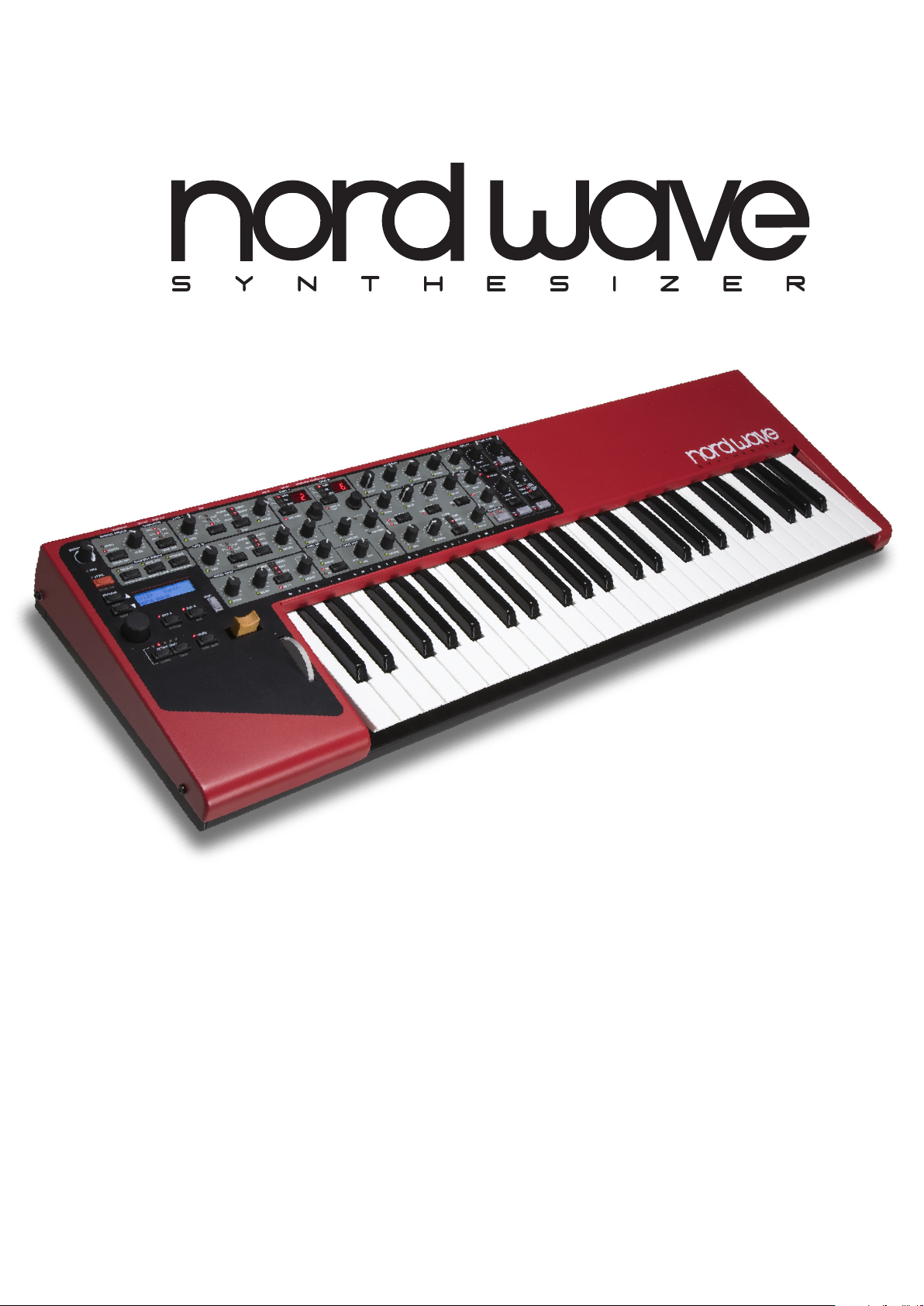
The Front panel
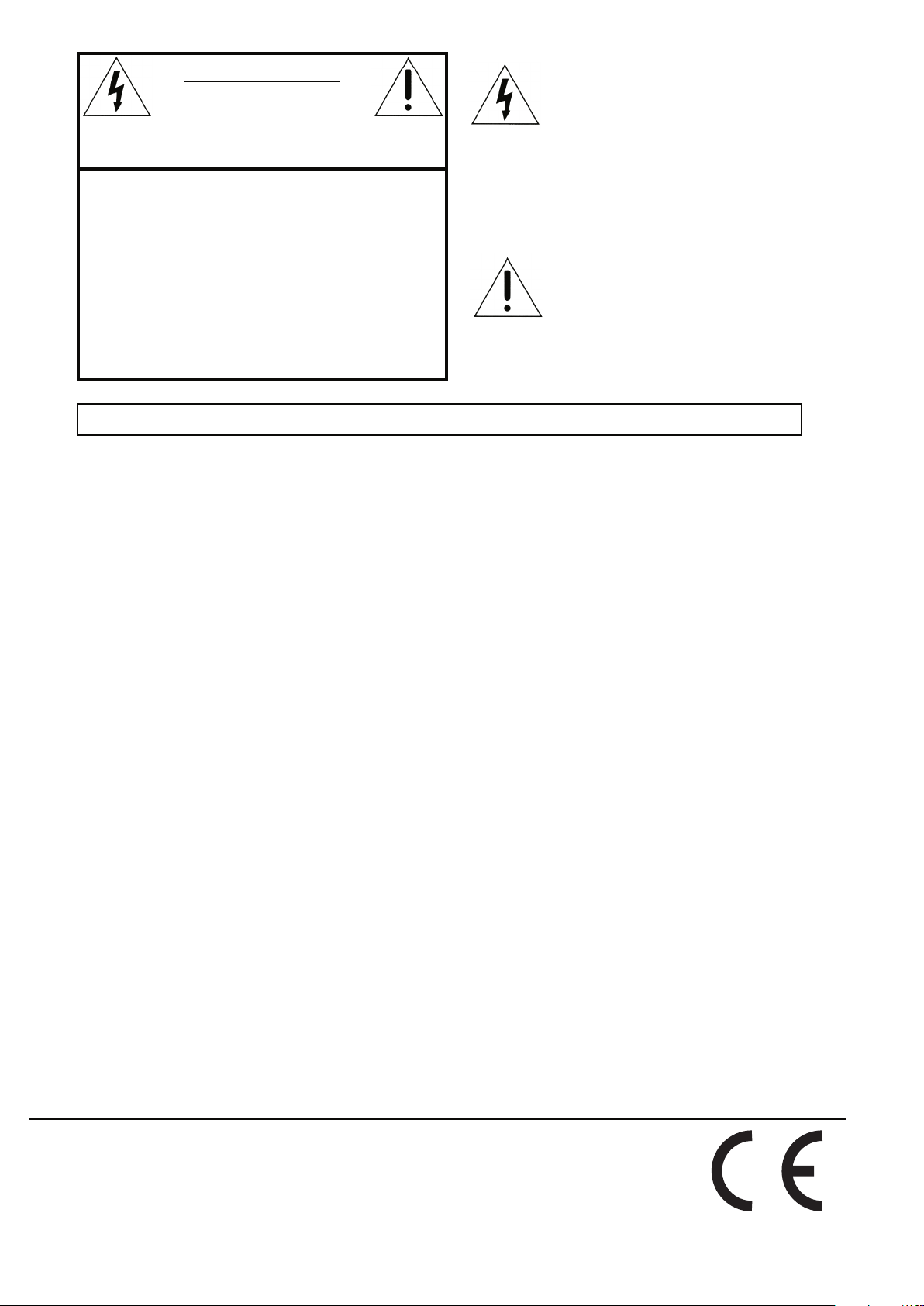
Program Section
The Program Section parameters are use for editing and
selecting program specic parameters.
Please refer to page 14 for more information.
For each program you have two individual Synth Sections
available, both controllable through the same panel, one at
a time. You choose which section to control by pressing the
SLOT A or SLOT B button.
For more information on Slot buttons please refer to page
10.
For more information on the Synth Section please refer to
page 16.
Effect Section
The Eect section parameters
are used for editing program
specic eect parameters. The
Eect Section is common for
both Synth sections. Please refer
to page 12 for more information.
Synth Section
The Synth Section parameters are all printed against a gray
background, and are used for editing synthesis related
parameters.
Page 7
2. OVERVIEW | 7
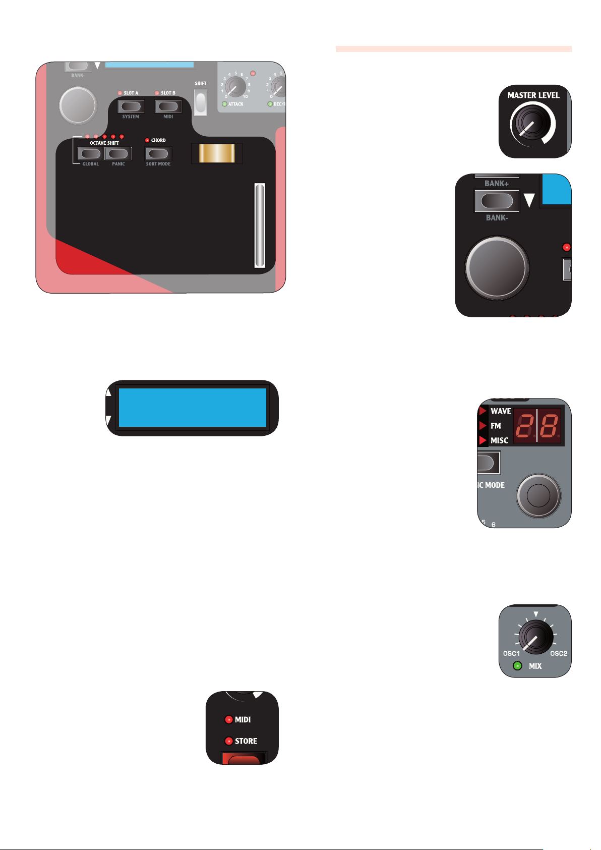
About knobs
MASTER LEVEL knob
The MASTER LEVEL knob controls the
overall amplitude for all audio outputs, including line level outputs and
headphone output. The MASTER LEVEL
knob’s physical position is always the
same as the output level.
LCD-dial
The LCD-dial is used for
changing the current setting displayed in the LCD
window. If not in the System
or MIDI Menu, this means
loading a new program.
The dial is endless, though
the array of parameter
settings are not; once you
Keyboard Section
The keyboard section consists of the keyboard, modulation
wheel, pitch stick and various keyboard related buttons.
Please refer to page 10 for more information.
LCD Window
The LCD
window is
normally used
for displaying
the current
program
bank, number, name and category.
When operating a knob or button the associated parameter name and setting will breiy show in the LCD window.
The LCD window is also used for displaying the System
menu or MIDI menu.
System Menu
The System Menu is used for editing system specic
parameters. You access it by pressing the SYSTEM button
(SHIFT + SLOT A).
Please refer to page 31 for more information.
reach the rst or last possible setting, turning the
dial further will have no
eect.
The dial has an accelerator feature; when operated swiftly
increasment/decreasment will be made in larger intervals.
If only one setting is available, turning the knob will
F
have no eect.
LED-dials
The dials have a LED window to
show their parameter setting.
When operating the dial the current setting is also shown briey
in the LCD window.
The dials themselves are endless,
though the array of parameter
settings are not; once you reach
the rst or last possible setting,
turning the dial further will have
no eect. The LED window will
update automatically when loading a program.
If only one setting is available (for instance if you
F
have only 1 sample in memory), turning the dial will
have no eect.
MIDI Menu
The MIDI Menu is used for editing MIDI specic settings.
You access it by pressing the MIDI button (SHIFT + SLOT B).
Please refer to page 29 for more information.
MIDI LED indicator
The MIDI LED will indicate incoming
MIDI note messages by briey lighting
up.
Potentiometer knobs
Potentiometer type knobs have a xed
range with start and end positions. The
knobs position is physically indicated
which make them convenient as you
instantly ‘feel’ the knobs position and
can easily operate the knob without
looking.
Note when loading a program; a parameter value can
F
be totally dierent from the knob’s physical position.
As soon as you start turning the knob the parameter
value will ‘snap’ to the knob’s physical position.
Most potentiometer type knobs have a green LED indicator
below them. This LED is used for indicating when a parameter is connected to a MORPH source. Please refer to page
27 for more information on morphing.
Page 8
8 | Nord Wave User Manual OS V1.00
Value indicators
The Modulation Envelope’s AMOUNT
LED as wel as the EQ’s TREBLE and
BASS LEDs will indicate a parameter
setting of zero by briey inverting the
LED’s state.
In the same manner, Oscillator 2’s SEMI
TONES LED will indicate a parameter setting equivalent of
whole octaves.
If the parameter • is not connected to a Morph Source: the
LED is unlit, and will light up for about half a second or
until the parameter setting is no longer at the indicated
value.
If the parameter • is connected to a Morph Source; the
LED is lit, and will be turned o for about half a second
or until the parameter setting no longer is at the indicated value.
About buttons
Slot buttons
Slot buttons are used
for setting panel and
keyboard focus .
Please refer to page 10
for more information.
OCTAVE SHIFT buttons
The OCTAVE SHIFT but-
tons are used for transposing the KEYBOARD in
whole octaves.
Please refer to page 10
for more information.
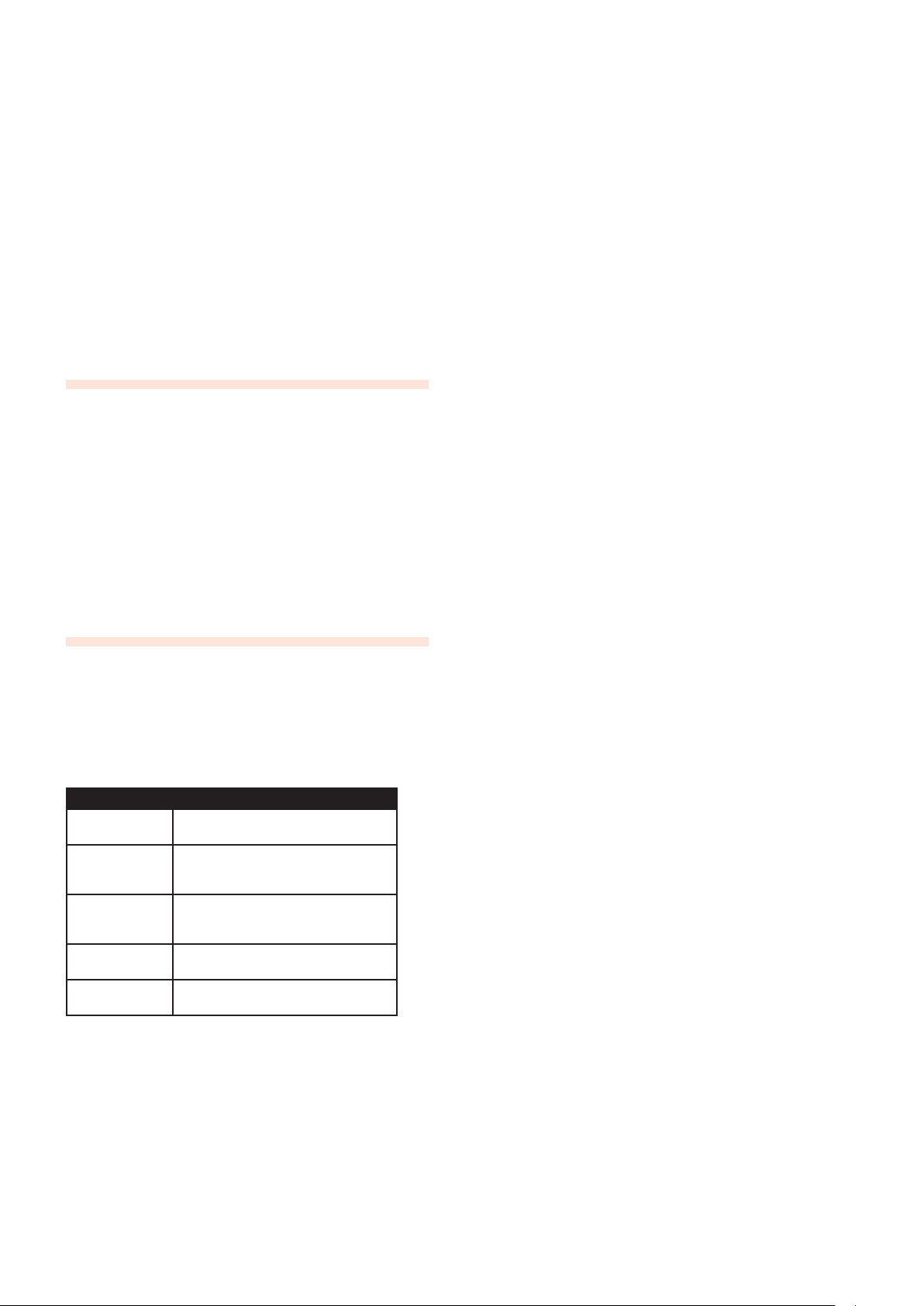
CHORD button
The CHORD button activates the Chord Memory
function, which is used
for memorizing note intervals and automatically
adding them to each key
you play.
Please refer to page 11 for more information.
Selector buttons
Selector buttons are used for activating one setting in an
array of two or more settings. Selector buttons have a set
of round or triangular LEDs to indicate the current setting.
If all LEDs are unlit, the parameter is bypassed or at its •
default state.
If two LEDs are lit, the parameter value with the corre- •
sponding bracket is selected.
On/off buttons
On/O buttons are used for activating
a parameter or a group of parameters
such as eects. The LED next to the
button will indicate when the parameter is active.
SHIFT button
Some buttons have a secondary function available by holding SHIFT while
pressing the button. The name of the
secondary function is printed just
below the button.
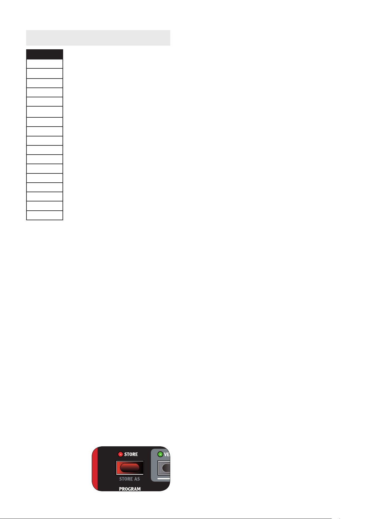
STORE button
The STORE button is
used for storing all your
settings into a Program.
Please refer to page 12
for more information.
PROGRAM buttons
The PROGRAM button are used for
loading the next or previous program.
They can also be used with the SHIFT
button to select the next or previous
Program Bank.
In the SYSTEM menu and the MIDI
menu they are used for selecting the
next or previous page.
Please refer to page 12 for more information.
PANIC button
By pressing the PANIC button (SHIFT +
OCTAVE SHIFT UP buttons) all sound-
ing notes will be silenced.
Note: Equipment connected via
F
MIDI OUT is not aected.
Page 9
3. CONNECTIONS | 9
Connections
3.
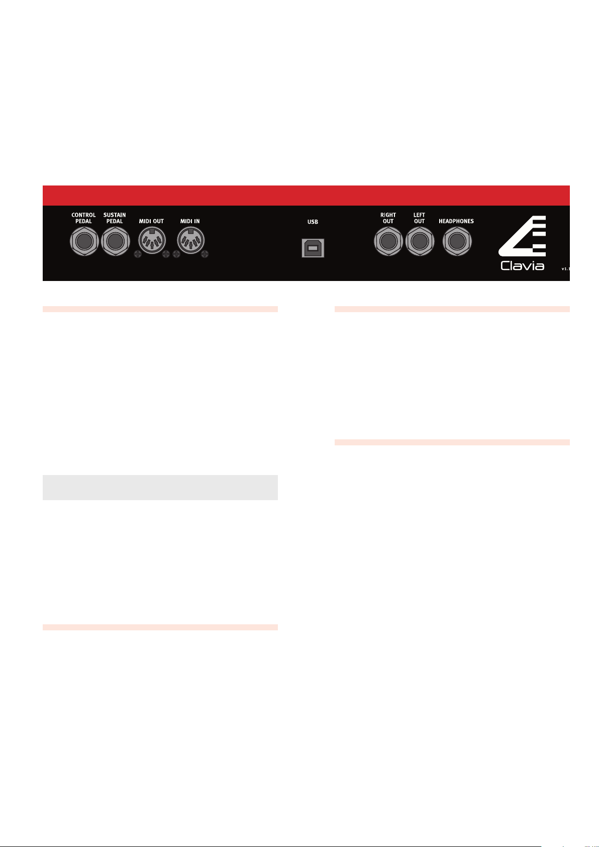
Audio Connections
LEFT OUT and RIGHT OUT
Mono-plug connections used as audio output to other line
level equipment.
To properly experience the Nord Wave, always use
F
both outputs in a stereo operation.
Headphones
Stereo-plug connection used for headphones.
General guide for audio connections
Make all connections before turning on the power to •
your amplier.
Turn • on the power to your amplier last.
Turn • o the power to your amplier rst.
Playing at a high volume level can result in hearing
F
impairments such as permanent hearing loss.
USB Connection
USB-plug connection used for communication with the
Nord Wave Manager software and OS system upgrades.
Computers running Microsoft Windows operating
F
systems need a driver for the USB connection to function. The driver can be found on the enclosed CD, or
on the Clavia website.
Pedal Connections
SUSTAIN pedal
Mono-plug connector for switch type pedals (also known
as sustain pedals) used for sustaining notes.
CONTROL pedal
Stereo-plug connector for pedals of potentiometer type
(also know as expression pedals) used as a source for the
Morph function or overall volume controll. Please refer to
page 27 for more information on Morphing.
MIDI connections
MIDI OUT
MIDI-plug connection used for transferring MIDI data to
other equipment such as sound modules or computers.
MIDI IN
MIDI-plug connection used for receiving MIDI data from
other equipment such as keyboards, sound modules and
computers.
Page 10
10 | Nord Wave User Manual OS V1.00
The Keyboard Section
4.
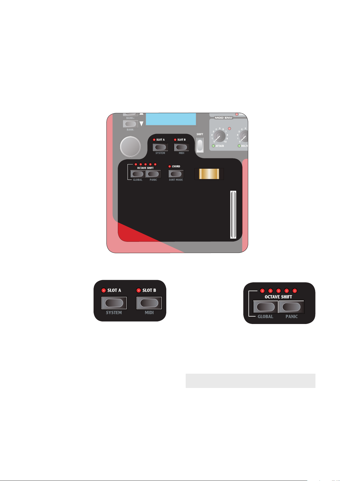
Panel & Keyboard Focus SLOT A & SLOT B
buttons)
Slot buttons are used
for setting Panel and
Keyboard Focus to either or both of the two
Synth Sections.
Panel Focus refers to •
the knobs and buttons of the Synthesizer Section.
Keyboard Focus refers to the controls and buttons of •
the Keyboard Section, the KEYBOARD and the pedal
inputs.
Only one slot can have Panel Focus at one time, where as
both slots can simultaneously have Keyboard Focus.
Use the • SLOT A or SLOT B buttons to set Panel Focus
the corresponding slot’s Synth Section.
Press both slot buttons simultaneously to set key- •
board focus to both slots. In this mode both LEDs are
lit, and the slot with Panel Focus will have a ashing
LED.
With Keyboard Focus set to both slots, press both slot •
buttons again to set keyboard focus to only one slot.
When pressing both slot buttons simultaneously,
F
the button you press rst will be in focus.
Keyboard and Panel Focus is only used locally. Both
F
Synth Section are always available to other equipment connected via MIDI in (on the slots corresponding MIDI channel) regardless of the Keyboard
and Panel Focus setting.
OCTAVE SHIFT buttons
The OCTAVE SHIFT
buttons transpose the
Synth Section with
Panel Focus in even
octaves.
The center LED indicates that no octave
shift is applied.
LEDs to the right of •
the center LED will indicate a higher octave shift as
you press the right OCTAVE SHIFT button.
LEDs to the left of the center LED will indicate a lower •
octave shift as you press the left OCTAVE SHIFT but-
ton.
Equipment connected via FMIDI OUT is not aected.
Global Octave Shift
By pressing the GLOBAL button (SHIFT + OCTAVE SHIFT
down) you can transpose the KEYBOARD in even octaves.
The LEDs are in an inverted state to reect that you are in
Global Octave Shift mode. In this mode, both slots as well
as equipment connected via MIDI OUT is eected.
Note: a combination of extreme FOCTAVE SHIFT and
OSC 2’s SEMI TONES setting can produce sounds
outside the hearing range.
Page 11
4. THE KEYBOARD SECTION | 11
CHORD button
The CHORD button activates the
Chord Memory function, which is used
for memorizing note intervals and
automatically adding them to each key
you play.
The Chord Memory settings are stored
within a Program.
Play a chord and press & hold the 1 CHORD button.
The display will show the intervals of the notes in
the played chord based on the lowest note (which is
displayed as 0).
Release the 2 CHORD button first, then the chord.
The note intervals are memorized and the Chord
Memory function is activated.
If you want to cancel the Chord Memory function
F
while holding the CHORD button pressed down, simply release the chord rst, then the CHORD button.
Now, the intervals stored in the Chord Memory will be
added automatically to each note you play.
Press the 3 CHORD button to deactivate the Chord Memory
function.
Once deactivated, you can at any time press the
CHORD button again (without holding any keys
down) to activate it.
Note that since you use several notes in the Chord
F
Memory function, polyphony will be reduced.
Note that it is only the actual key(s) you play that will
F
output MIDI Note information to the MIDI OUT - not
the intervals included in the Chord Memory!
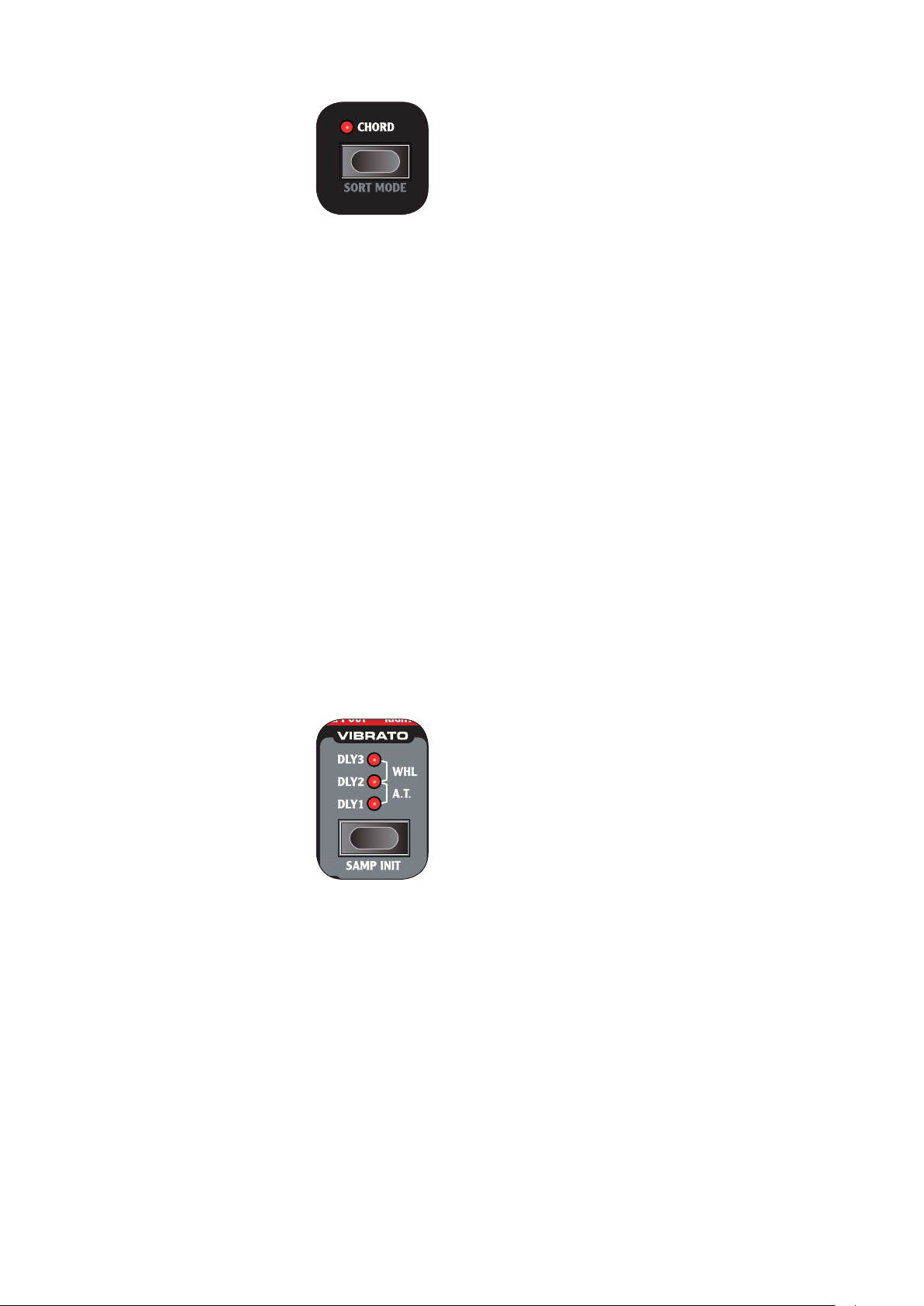
Modulation wheel
The modulation wheel can be used to
apply vibrato to the sound, as well as a
source for the Morph function.
The set the MODULATION WHEEL
to control vibrato, press the VIBRATO
selector button until the LEDs indicate
WHEEL.
Vibrato setting is individual for
F
SLOT A and sLOT B.
Please refer to page 27 for information
on the Morph function.
Pitch stick
The Clavia patented wooden PITCH STICK gives you spot
on bending control just like that of a guitarist. The pitch interval is locked to 2 semi tones, and is activated dependant
on Keyboard Focus setting.
Page 12
12 | Nord Wave User Manual OS V1.00
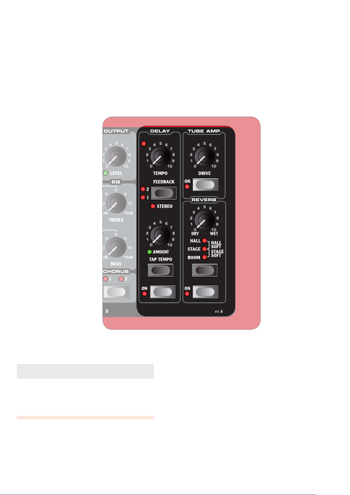
The Eect Section
5.
The Eect section holds 3 eects common to both Synth
Sections. Eect settings are stored within a Program.
The ON knob activates/deactivates the eect.
About Unison and EQ
The CHORUS and EQ eects are individual to both Synth
Sections. Please refer to page18 for more information.
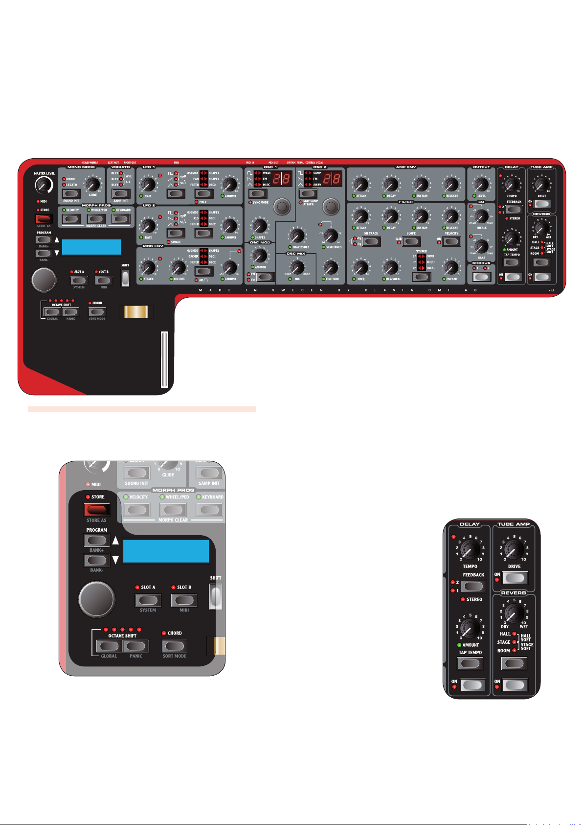
Delay
The DELAY eect ads vintage-style delayed repeats to your
sound.
TEMPO LED
The TEMPO LED indicates the current tempo setting.
AMOUNT knob
The AMOUNT knob controls the balance in amplitude between the unprocessed (DRY) and processed (WET) signal.
When set to either FDRY or WET, only the corresponding signal will be heard.
TEMPO knob
The TEMPO knob controls the time interval of the delayed
repeats.
FEEDBACK button
The FEEDBACK button selects presets of number of delayed repeats.
Note that the LEDs labels ( F1 and 2 refers to the
preset number, and not the actual number of delayed
repeats.
Page 13
5. THE EFFECT SECTION | 13
STEREO button
The STEREO button (SHIFT + FEEDBACK button) activates
the delay in stereo operation.
TAP TEMPO button
The TAP TEMPO button controls the tempo setting of the
delay eect. By repeatedly tapping the button, the tempo
is set to match the interval of your taps.
The tempo LED will indicate while the tempo is being
F
calculated. As long as it is lit, your rst tap will be
used as a reference. Wait till it goes dark to start with
a new reference.
Tube amp
The TUBE AMP eect adds tube-style overdrive to your
sound.
DRIVE knob
The DRIVE knob controls the amount of overdrive applied
to your sound.
A setting of zero will produce no overdrive.
F
Reverb
The REVERB eects simulates natural sound reections in
various acoustic environments.
REVERB button
The REVERB button selects the type of environment:
Setting Description
ROOM
STAGE SOFT
STAGE
HALL SOFT
HALL
Small reverberation with room ambiance and a fast decay.
Medium reverberation with stage
ambiance, medium decay and a mellow
character.
Medium reverberation with stage
ambiance, medium decay and a bright
character
Full reverberation with a hall ambiance,
slow decay and a mellow character.
Full reverberation with a hall ambiance,
slow decay and a bright character.
DRY/WET knob
The DRY/WET knob controls the balance in amplitude between the unprocessed (DRY) and processed (WET) signal.
When set to either FDRY or WET, only the corresponding signal will be heard.
Page 14
14 | Nord Wave User Manual OS V1.00
2:17 Lead
Freaky Nord
2:17 Lead
Freaky Nord
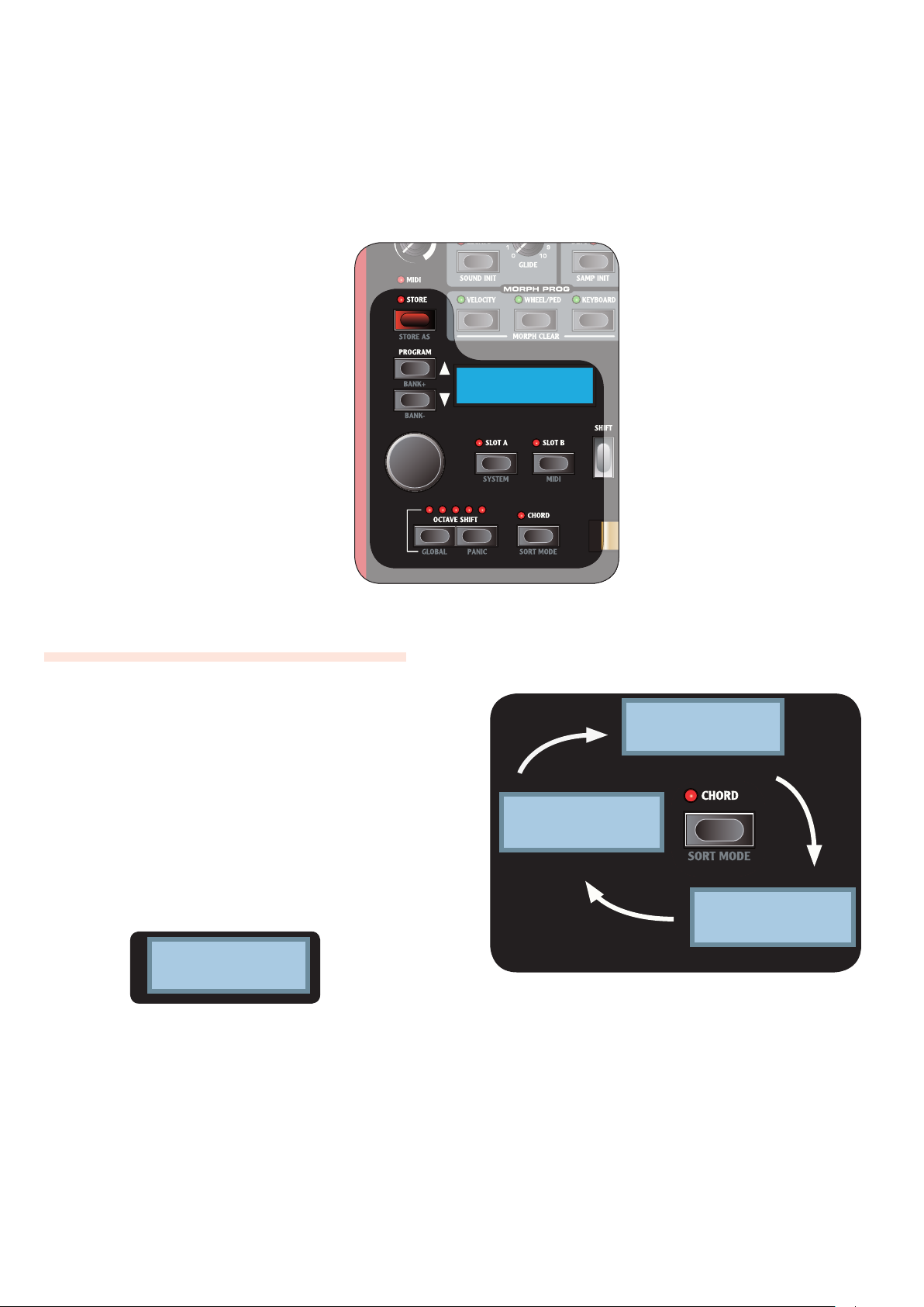
Numerical sort order
Lead 2:17
Freaky Nord
Category sort order
F 2:17
Freaky Nord
Alphabetical sort order
The Program section
6.
What is a Program?
All sound related settings can be saved into a Program.
A Program can be instantly recalled to produce the same
sound as when you saved it. These settings include: both
Synth Sections, Panel and Keyboard focus (SLOT A and
SLOT B buttons), EFFECTS, CHORD MEMORY, OCTAVE
SHIFT and MORPH settings.
MIDI F menu and SYSTEM menu settings are not stored
whit in a program, but are global i.e.; their settings
eects all programs all the time.
There are 1024 program locations available, where every
location have a bank and program number. Programs also
have a name and can be divided into categories.
The currently loaded program is shown in the LCD DIS
PL AY.
In the example above 2 represents the Bank number, 17
the Program number,
Nord
the Program name.
Lead
the Category and
Freaky
Sorting Programs
Programs can be sorted Numerically, by Category or
Alphabetically by pressing the SORT MODE button (SHIFT
+ CHORD).
Page 15
6. THE PROGRAM SECTION | 15
List of Categories
CATEGORY
ACOUSTIC
BASS
DRUM
FANTASY
FX
LEAD
ORGAN
PAD
PIANO
PLUCK
STRINGS
SYNTH
VOCAL
WIND
USER1
USER2
USER3
LED starts ashing, and the Program location is shown
in the LCD WINDOW.
Press FSLOT A or SLOT B buttons at any time to cancel
the procedure.
Select a location2
Use the PROGRAM buttons or the LCD-dial to choose
a Program location.
Press the 3 STORE button to confirm
The selected Program is overwritten.
To store a Program and change the Program name and/
or Category:
Press the 1 SAVE AS button (SHIFT + SAVE)
The store button LED starts ashing and the Program
category and name is show in the LCD WINDOW.
Press FSLOT A or SLOT B buttons at anytime to cancel
the procedure.
First, use the 2 LCDDIAL to select a category, then give your
program a name using the PROGRAM buttons to change
letter position, and LCDDIAL to scroll between letters and
numbers.
Press the 3 STORE button to confirm the Product name
The Program category is show in the LCD WINDOW.
Loading a Program
Use the PROGRAM buttons to load the next or previous
program, depending on the current SORT MODE setting.
You can also use the LCD-dail to select Program.
Programs are loaded automatically.
F
When in Numerical Sort Mode (default):
Use the • BANK buttons (SHIFT + PROGRAM buttons) to
select the next or previous bank.
When in Category Sort Mode:
Use the • BANK buttons (SHIFT + PROGRAM buttons) to
select the next or previous Category.
When in Alphabetical Sort Mode:
Use the • BANK buttons (SHIFT + PROGRAM buttons) to
select the the next or previous initial letter.
Editing a Program
Editing a program is easy, just start turning the knobs and
buttons.
The LCD window will breiy show the selected param- •
eters name and setting.
A •* symbol next to the program number will indicate
that the current settings are not saved.
Press the 4 STORE button to confirm Program Category &
Name
The Program location is shown in the LCD WINDOW.
Use the Program buttons or the LCD-dial to choose
where to store the Program.
Press the 5 STORE button to confirm location
The selected Program location is overwritten.
Storing a Program
To store a Program
without changing Program name or category:
Press the 1 STORE
button
The Store button
Page 16
16 | Nord Wave User Manual OS V1.00
The Synth Section
7.
The Synth Section is the area where knobs and buttons
have a gray printed background. These knobs and buttons
controls the sound engine of the Nord Wave.
There are two sound engines available simultaneously,
though they are edited via the front panels knobs and
buttons one at a time. The SLOT A and SLOT B buttons are
used to activate a Synth Sections, and to set Panel Focus.
Please refer to page 11 for more information.
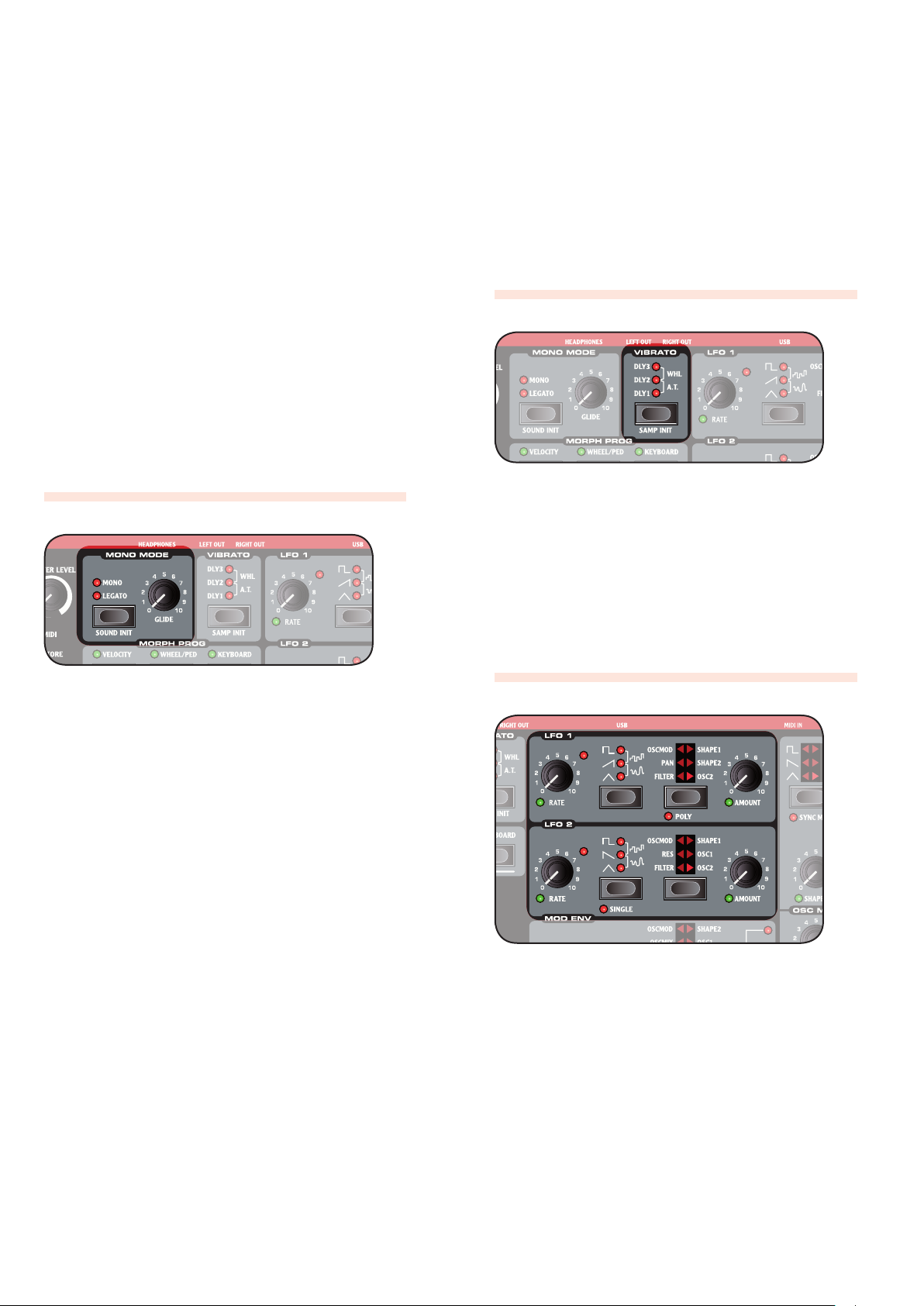
MONO MODE
With Mono Mode activated, the Nord Wave will function as
a monophonic synthesizer, only one note can be played at
any time.
VIBRATO
The VIBRATO function will gradually introduce subtle to
dramatic changes in pitch.
D LY1 • -3 setting will introduce changes over time. Time
interval range from short to long.
A.T. • setting will introduce changes as you apply AFTER
TOUCH.
WHEEL • setting will introduce changes as you operate
the MODULATION WHEEL.
LFO (LFO1 & LFO2)
Selector button
If you press a key without releasing the previous one:
MONO • setting will re trigger envelopes; the sound will
“re-start” for each note you play.
LEGATO • setting will not retriever envelopes; the sound
will “continue” with only a change in pitch.
GLIDE knob
If you press a key without releasing the previous one, the
Glide parameter can be used to set the time interval for the
pitch to seamlessly change to the new note. With a setting
of zero the pitch will change instantly.
The LFO is used to repeatedly modulate various parameters using a Low Frequency Oscillator; an oscillator generating various types of waveforms with very low pitch.
You never hear the actual LFO, only the modulation
F
of the selected parameter.
There are two LFOs available, with slightly dierent features described below.
RATE knob
The RATE knob is used to set the frequency of the LFO; the
time it takes for the waveform to restart.
The FRATE LED will indicate each time a waveform is
started.
Page 17

7. THE SYNTH SECTION | 17
Waveform selector
The Waveform Selector button determines what waveform
is generated by the LFO.
Waveform Description LFO 1 LFO 2
Square
Used for abrupt modulation changes, suitable
for trills, distinct tremolos, etc.
Sawtooth
Used for ramp type
modulations.
Inverted Sawtooth
Used for ramp type
modulations.
Triangle
Creates natural vibrato
eects and also used
for classic pulse width
modulation.
Stepped Random
Creates abrupt modulation with random
intensity.
Smooth Random
Creates a smooth random modulation.
Ye s Ye s
No Yes
Ye s No
Ye s Ye s
Ye s Ye s
Ye s Ye s
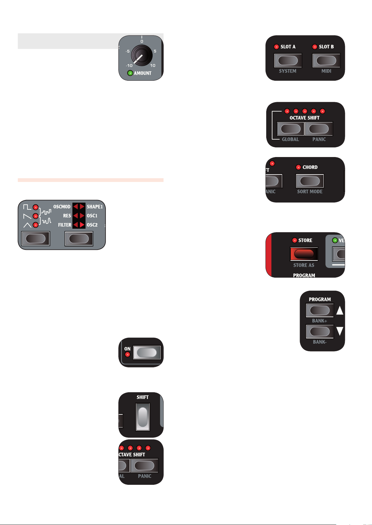
LFO Destination selector
The LFO Destination determines what parameter is modulated.
Destination Description LFO 1 LFO 2
FILTER Modulates the Filter
RES Modulates the Filter
PAN Modulates the dif-
OSC
MOD
SHAPE Modulates the Oscilla-
OSC1 Modulates the pitch of
OSC2 Modulates the pitch of
Frequency parameter
(FREQ knob).
Resonance parameter
(RES knob).
ference in amplitude
between the left and
right output.
Modulates the Oscillator Modulation Amount
parameter.
tor Shape parameter
(SHAPE knob).
Oscillator 1.
Oscillator 2.
Ye s Ye s
No Yes
Ye s No
Ye s Ye s
Ye s Ye s
Ye s Ye s
Ye s Ye s
SINGLE mode
With single mode activated, the LFO plays a single cycle
waveform once without repeating.
Single mode is available to LFO 2 only.
F
Modulation Envelope (MOD ENV)
The Modulation Envelope is used to modulate various
parameters using an Envelope with Attack and Decay or
Release parameters.
Please refer to page 18 for general information on envelopes.
AT TACK knob
Use the AT TACK knob to set the time interval of the Attack
part of the Envelope. With a setting of zero the Attack Level
will start instantly.
DEC/REL knob
Dependant on the AR setting, this knob has dierent functions:
AR setting disabled
The DEC/REL knob controls the time interval of the Decay
part of the envelope.
AR setting enabled
The DEC/REL knob controls the time interval of the Release
part of the envelope.
AR button (SHIFT + Destination Selector button)
The AR button toggles the envelope Attack/Release mode:
When disabled the • DEC/REL knob controls the enve-
lope’s Decay parameter. The envelope’s Sustain Level is
set to null.
When enabled the • DEC/REL knob controls the enve-
lope’s Release parameter. The envelope’s Sustain Level is
set to full.
AMOUNT knob
The AMOUNT knob sets the intensity of the modulation. A
setting of 0 will produce no modulation.
POLY mode
In Poly mode each note has its own LFO. Poly mode is
activated by pressing the POLY button (SHIFT + Waveform
Selector button).
Poly mode is available to LFO 1 only.
F
AMOUNT knob
The Amount knob sets the intensity of the modulation.
A setting of 0 will produce no modulation. •
A negative value will produce a negative modulation. •
A positive value will produce a positive modulation. •
Page 18

18 | Nord Wave User Manual OS V1.00
Envelopes
Envelopes are used for altering various parameter settings over time, using the time you press and release a key as trigger points.
• When a key is pressed, the envelope
starts at its base level, and gradually
fades to full during the time set by
the Attack Time (ATTAC K knob).
Once reaching full, the envelope will •
gradually fade to the Sustain Level
(SUSTAIN knob), during the time set
by the Decay Time (DECAY knob).
When the key is released, the sound •
will gradually fade to zero during
the time set by the Release Time
(RELEASE knob).
Use the Release parameter to set the
time interval for the Release part of the
Envelope. With a setting of zero the
envelope will instantly reach zero as
you release the key.
With the Sustain Level set to zero,
F
operating the Release knob will
have no eect.
Using a time setting of zero can
F
produce clipping sounds to occur; to eliminate any click, just
increase the Time setting slightly.
There are a total of four envelopes
available:
The image above illustrates the modulation envelope with Attack and Decay parameters.
The image above illustrates the modulation envelope with Attack and Release parameters.
The envelope’s base relates to the •
current setting of the selected target
parameter, and spans to the intensity set by the ENV AMT knob.
Please refer to page 17 for more information.
Use the Attack parameter to set the
time interval for the Attack part of the
Envelope. With a setting of zero the
Attack Level will start instantly.
Use the Decay parameter to set the
time interval for the Decay part of the
Envelope. With a setting of zero the
Sustain Level will start instantly after
the Attack part of the Envelope.
With the Sustain Level set to full,
F
operating the DECAY knob will
have no eect.
Amplier Envelope (AMP ENV)
The Amplier Envelope is the most important
one; it controls the amplitude of your sound and
is used to give the sounds its basic “shape”.
The envelope’s base relates to null •
amplitude and spans to the level set
by the OUTPUT LEVEL knob.
Please refer to page 23 for more information.
Filter Envelope
The Filter Envelope controls the Filter Frequency
parameter and can be very dramatic.
The envelope’s base relates to the •
Filter Frequency set by the FREQ
knob, and spans to the intensity set
by the Filter’s ENV AMT knob.
Please refer to page 25 for more information.
Sample Playback envelope
When Sample Playback (SAMP) is
selected as Oscillator Waveform type
a special decay only envelope is available to that oscillator only.
The image above illustrates the decay
only envelope.
By setting the FSHAPE1/DEC
knob to full the Decay parameter
will have an innite setting; the
envelope will have no eect on
your sound.
Please refer to page 20 for more information.
Use the Sustain parameter to set the
level of the Sustain part of the Envelope. With a setting of zero the sound
will be silent after the Decay part of the
envelope.
Modulation Envelope (MOD ENV)
The Modulation Envelope is very powerful as you
select what parameter to control. It is a simplied
envelope with only Attack and Decay or Attack
and Release parameters.
Page 19

7. THE SYNTH SECTION | 19
Low-pitched note
High-pitched note
Destination selector button
The Destination selector button is used to select the target
of the modulation. .
Panel Description
SHAPE2 The Shape parameter of OSC2
OSC1 The pitch of OSC1
OSC2 The pitch of OSC2
FILTER The Filter Frequency parameter
OSCMIX The OSC Mix parameter
OSCMOD The Amount parameter of the Oscilla-
tor Modulation
Note that both FOSC1 and OSC2 can be selected simultaneously.
Oscillator (OSC1 & OSC2)
refer to “Oscillator Waveform Types” on page 20 for more
information.
SEMI TONES knob
The SEMI TONES knob is used for changing the pitch of
OSC2 relative to OSC1 in steps of semi tones, ranging from
-24 (-2 octaves) to +24 (+2 octaves) semi tones.
The red LED will briey indicate a pitch setting of even
F
octaves.
FINE TUNE knob
The FINE TUNE knob is used for changing the pitch of
OSC2 relative to OSC1 ranging from -0.5 to +0.5 semi
tones.
While having an equal FOSC MIX setting, and a SEMI
TONES setting of 0; slightly rasing or lowering the ne
tune parameter will produce a “richer” sound.
Oscillator Modulation (OSC MOD)
Oscillator modulation is all about having the waveform
produced by OSC2 modulating OSC1. OSC1 will produce a
richer waveform with more resonant harmonics the more
modulation you apply.
By changing the frequency of OSC2, you change the
F
harmonic content of OSC1 - not its frequency.
The Oscillator is the source of your sound, where the basic
waveform is generated.
There are two Oscillators available, so that you can play
two waveforms simultaneously. Further than just combining the output of the two Oscillators, one oscillator can also
modulate the other, creating very complex and constantly
changing waveforms.
The two oscillators have slightly dierent features described below.
Oscillator Waveform selector
The Waveform Selector button determines what type of
waveform is generated by the Oscillator.
If the waveform is of multi-type you can use the Waveform Selector dial to further select what waveform should
be generated. The LED window will show the currently
selected waveform.
Please refer to “Oscillator Waveform Types” on page 20 for
more information.
Shape parameter (SHAPE1 & SHAPE2/DEC
knob)
The Shape parameter is used for altering the waveform
generated by the Oscillator. The exact functionality varies
depending on what type of waveform is generated. Please
This is the same principle as FM-synthesis (described on
page 21), but is far more powerful as you can have the oscillators set-up to produce any waveform you like - including sample playback.
Also the waveform produced by OSC2 can be heard by us-
ing the OSC MIX AMOUNT knob.
There are two types of modulation available: Frequency
Modulation (FM) and Phase Modulation (PM).
Frequency Modulation (FM)
Frequency Modulation generates more frequency bands
and the resulting sound is normally perceived as rawer
and brighter. The harmonic content changes drastically
depending on in what note range you play.
The image above illustrates the harmonic content for a
low-pitched note and a high-pitched note using Frequency
Page 20

20 | Nord Wave User Manual OS V1.00
Single cycle loop
Attack section
Oscillator Waveform Types
Oscillators are used for generating various kinds of waveforms; these waveforms are the foundation or starting block of your sound.
Pulse
The default Pulse
waveform is available to OSC1 and
OSC2 and has a
hollow character
with only odd
harmonics, but can drastically change
as the with of the pulse is altered.
The • SHAPE knob is used for chang-
ing the pulse with from 50% to 1%.
The image above shows the Pulse
waveform at 50% width. Only odd
harmonics are present.
The image above shows the Pulse
waveform at 10% pulse width. Now,
also even harmonics are gradually
introduced making the sound “sharper”
but also “thinner”.
Sawtooth
The Sawtooth
waveform is available to OSC1 and
OSC2 and produces a very rich
sound containing
all harmonics.
The image above shows the default
Sawtooth waveform containing all
harmonics.
The • SHAPE parameter has normally
no function.
If • OSCILLATOR SYNC is activated,
the SHAPE knob is used for controlling the pitch of the Sync Oscillator.
Triangle
The Triangle
waveforms is
available to OSC1
and OSC2 and
has only odd and
not very strong harmonics.
Wavetable is briey shown in the
LCD window.
The • SHAPE parameter has no func-
tion.
Sample Instruments
Sample Instruments (SMPL) is
available to OSC2
and holds up to
99 Sample Instruments containing key-layered
samples (recorded audio data) stored in the Flash
memory area.
A large selection of high quality
samples are installed when shipped
from the factory, and even more can
be downloaded free of charge from the
Clavia web site.
Use the • LED-dial to select Sample
Instrument. The name of the selected Sample Instrument is shown
in the LCD WINDOW.
A ashing
F
DISPLAY indicates that no Sample
Instruments are available in the
Flash area.
There is a special OSC2 only, amplitude
decay envelope available in Sample
Instrument mode. Use the SHAPE2/
DEC knob to control the decay time of
the OSC2 amplitude envelope.
When the • SKIP SMPL AT TACK (SHIFT
+ Waveform Selector button) is
activated, playback will start at an
alternative startpoint, skipping the
attack part of the sound.
-- character in the LED
The image above shows the Pulse
waveform at 1% pulse width. The
narrower the pulse width, the more
harmonics are introduced.
If you modulate the Shape value
F
using an LFO, you can get very
nice “synthesized strings”.
If • OSCILLATOR SYNC is activated,
the SHAPE knob is used for controlling the pitch of the Sync Oscillator.
The pulse width is locked at 33%.
The image above shows the Triangle
waveform.
The • SHAPE parameter has normally
no function.
If • OSCILLATOR SYNC is activated,
the SHAPE knob is used for controlling the pitch of the Sync Oscillator.
Wavetable
Wavetables
(WAVE) are available to OSC1 and
are single cycle
sampled waveforms that provides rich and interesting
timbres of various tonal characteristics.
There are 32 Wavetables available.
Use the • LED-dial to select Wavet-
able. The name of the selected
Sampled waves
Sampled waves
(SAMP) are available to OSC2
and are similar
to wavetables,
but are made out
of recodings of
acoustic instruments and still have the
attack section of the sample present.
The image above shows the structure
of a sampled wave.
Use the • LED-dial to select sampled
wave.
The • SHAPE parameter has no func-
tion.
Page 21

7. THE SYNTH SECTION | 21
Shape2
(FM Amount)
Shape1
(FM Amount)
Carrier
Carrier
OSC MIX
OSC MOD
Modulator Modulator
Shape
(Feedback)
Shape
(FM Amount)
Shape2
(FM Amount)
Shape1
(FM Amount)
Shape
(Feedback)
Carrier
Carrier
Carrier
Carrier
Modulator
OSC MIX
OSC MOD
Modulator Modulator
Note that a single Oscillator
FM-Synthesis
FM-Synthesis
(FM) is available
F
(OSC1 or OSC2) in this scenario
actually contains two oscillators.
to OSC1 and
OSC2 and is all
about having
one Oscillator
(referred to as
FM-algorithms using only 1 operator
(Carrier only) is also available, indicated
as
1-OP
in the LCD window, and CR in
the LED window.
the Carrier) being modulated by itself
(using Feedback) or, by an additional
Oscillator (referred to as the Modulator).
Feedback
The rst Operator in the chain can be
given feedback to modulate itself, cre-
ating more complex modulations.
The image above shows the Sine waveform, generating only the fundamental
harmonic.
The • SHAPE parameter is used for
controlling both the feedback and
FM amount simultaneously.
Misc
The Misc category is available
to OSC1 and
currently only
holds the noise waveform, but various
waveforms might be added in future
upgrades.
The image above shows a 2 Operator
FM-Synthesis setup, and the resulting waveform using a fairly high FM
amount setting.
The resulting waveform is far more rich
in harmonics than the original Sine
waveform, and drastic changes in tonal
character are provided by altering the
amount of modulation.
There are several FM algorithms available; set-ups with various number of
oscillators, feedback and frequency
ratio settings between the oscillators.
Use the • LED-dial to select FM-algo-
rithm.
The • SHAPE parameter is used for
setting the amount of modulation
and/or feedback from none to full.
An FM algorithm using Feedback is in-
dicated by showing
(+FB)
in the LCD,
and a dot (.) in the LED window.
Frequency ratio
By giving the Modulator a dierent
frequency relative to the Carrier, the
resulting waveform continuously
changes in harmonic content.
Noise
The Noise waveform produces a noise
type of sound (as oposed to a pitched
sound generated by the other types of
waveforms).
The image above shows the frequency
content of the noise waveform; it is
very close to that of white noise (where
all frequencies are represented with
equal energy).
The • SHAPE parameter is used to
apply a 12db steep low pass lter to
OSC1 only.
By combining OSC1 and OSC2, up to 4
Operator FM-Synthesis is available, using Oscillator Modulation (OSC MOD) .
Oscillator Modulation is de-
F
scribed on page 19.
Operators
A set-up with 2 oscillators (one Carrier
and one Modulator) is referred to as
2 operator FM-Synthesis, indicated as
2-OP
in the LCD window.
The Image above shows the Modulator
having a frequency ratio of 9:1 relative
to the frequency of the Carrier, and the
resulting waveform using a fairly high
FM amount setting.
Frequency Ratios are indicated by
showing for example
9:1
in the LCD,
and simplied 9 in the LED window.
Sine
The Sine waveform is not available as
a selectable Waveform Type, but can
be generated by setting the Waveform
Selector to FM and setting the SHAPE
parameter to null.
Page 22

22 | Nord Wave User Manual OS V1.00
Low-pitched note
High-pitched note
Low-pitched note
High-pitched note
Modulation.
Some notes can sound more or less out-of pitch using
F
high amounts of Frequency Modulation; this behavior is considered normal.
Phase Modulation (PM)
Phase modulation generates the same relative harmonic
content regardless of in what note range you play, and is
perceived as more uent, similar to using keyboard tracking with the lter.
The image above illustrates the harmonic content for a
low-pitched note and a high-pitched note using Phase
Modulation.
AMOUNT knob
The AMOUNT knob controls the amount of modulation.
A setting of null will produce no modulation.
F
Only the output of the main oscillator is heard, but since
its waveform is constantly restarted, it produces a richer
harmonic content.
By altering the frequency of the main oscillator, a dierent
harmonic content is produced.
Use the • SHAPE knob to change the frequency of the
main oscillator.
TYPE button
The type button selects the type of modulation; Frequency
modulation (FM) or Phase modulation (PM). It is also used
for turning Oscillator Modulation o (both LEDs are unlit).
Oscillator mix (OSC MIX)
MIX knob
The Oscillator Mix parameter
is used for setting the balance
in amplitude between Oscillator 1 and Oscillator 2.
With a setting of either OSC1
or OSC2, only the corresponding
oscillator will be heard.
Due to dierences in the harmonic content produced
F
by the two oscillators, their amplitude levels can be
perceived as unequal though the OSC MIX parameter
is set to an equal mix; this is considered normal.
The image above illustrates a triangle waveform synchronized by a sine waveform.
Oscillator Sync (SYNC)
When OSC1 is set to produce either pulse, triangle or saw
waveforms, oscillator sync is available by activating the
SYNC function (SHIFT + Waveform Selector button).
When the SYNC function is activated an additional oscillator is available. Each cycle of the waveform produced by
the additional oscillator will restart the waveform generated by the main oscillator.
The image above illustrates the harmonic content of the
non-synchronized triangle waveform compared to the
synchronized one in the previous example.
Page 23

7. THE SYNTH SECTION | 23
Filter Frequency
Filter Frequency
Filter Frequency
Filter Frequency
Filter Frequency
Filter Frequency
Filter Frequency
Resonance = 10
Resonance = 0
Resonance = 3
Resonance = 7
Filter Frequency
Resonance = 10
Resonance = 0
Filter Frequency
Filter Frequency
Resonance = 10
Resonance = 0
Filter Frequency
Filter Frequency
Filter Frequency
Amplifier Envelope (AMP ENV)
The Amplier Envelope is used for controlling how the
amplitude of your sound changes over time.
Please refer to page 18 for general information on envelopes.
Simultaneously setting the Attack, Decay and Sustain
F
parameters to zero will result in silence.
AT TACK knob
Use the AT TACK knob to set the time interval for the Attack
part of the Envelope. With a setting of zero the Attack Level
will start instantly.
DECAY knob
Use the DECAY knob to set the time interval for the Decay
part of the Envelope. With a setting of zero the Sustain Level will start instantly after the Attack part of the Envelope.
With the Sustain Level set to full, operating the FDE
CAY knob will have no eect.
some multi mode lters.
TYPE button
This TYPE button sets the lter type. Please refer to “Filter
Types” on page 24 for more information.
Filter Frequency FREQ knob)
The Filter Frequency is used for setting where - in the frequency range - the lter is introduced.
The Image above illustrates dierent Filter Frequency settings using a Low Pass lter.
For Multi Mode lters the function of FFREQ knob varies. Please refer to “Filter Types” on page 24 for more
information.
SUSTAIN knob
Use the SUSTAIN knob to set the level of the Sustain part of
the Envelope. With a setting of zero the sound will be silent
after the Decay part of the envelope.
RELEASE knob
Use the RELEASE knob to set the time interval for the
Release part of the Envelope. With a setting of zero the
envelope will instantly reach zero as you release the key.
Filter
With the Sustain Level set to zero, operating the
F
Release knob will have no eect.
Filter Resonance (RES knob)
Filter Resonance is used to emphasize frequencies around
the Filter Frequency, making the sound thinner. Further
raising the Filter Resonance will make the sound resonant
to a point where the lter adds a ringing quality to the
sound. Exactly where in the frequency spectrum this “ringing” occurs, depends on the setting of the Filter Frequency.
The functionality of the FRES knob varies dependant
on what type of lter is selected. Please refer to “Filter
Types” on page 24 for more information.
Keyboard Tracking (KB TRACK button)
Keyboard Tracking is used for changing the Filter Frequency depending on what note you play.
The Filter is one of the most important components for
shaping the overall timbre of the sound. The Nord Wave
features a selection of classical single mode lters as well as
This is related to basic acoustics; if you raise the pitch of a
waveform, the harmonics naturally raise in frequency. If the
Filter Frequency is constant, the sound will be perceived as
getting “muddier” the higher up the keyboard you play.
With • KB TRACK disabled, the Filter Frequency setting is
constant regardless of where on the keyboard you play.
Page 24

24 | Nord Wave User Manual OS V1.00
Filter Frequency
Resonance = 10
Resonance = 0
Resonance = 3
Resonance = 7
Filter Frequency
Filter Frequency
Filter Frequency
Resonance = 10
Resonance = 0
Resonance = 3
Resonance = 7
Filter Frequency
Resonance = 10
Resonance = 0
Filter Frequency
Filter Frequency
Filter Frequency
Filter Frequency
Filter Frequency
Resonance = 10
Resonance = 0
Resonance = 3
Resonance = 7
Filter Frequency
Resonance = 10
Resonance = 0
Filter Frequency
Filter Frequency
Resonance = 10
Resonance = 0
Filter Frequency
Filter Frequency
Filter Frequency
Filter Frequency
Filter Frequency
Filter Frequency
Resonance = 10
Resonance = 0
Resonance = 3
Resonance = 7
Filter Frequency
Resonance = 10
Resonance = 0
Filter Frequency
Filter Frequency
Resonance = 10
Resonance = 0
Filter Frequency
Filter Frequency
Filter Frequency
Filter Frequency
Filter Frequency
Filter Frequency
Filter Frequency
Filter Frequency
Filter Resonance
Filter Frequency
Resonance = 10
Resonance = 0
Resonance = 3
Resonance = 7
Filter Frequency
Resonance = 10
Resonance = 0
Filter Frequency
Filter Frequency
Resonance = 10
Resonance = 0
Filter Frequency
Filter Frequency
Filter Frequency
Filter Frequency
Filter Frequency
Filter Frequency
Filter Frequency
Filter Frequency
Filter Resonance
Filter Frequency
Filter Vocal
Filter Frequency
Filter Frequency
Resonance = 10
Resonance = 0
Resonance = 3
Resonance = 7
Filter Frequency
Resonance = 10
Resonance = 0
Filter Frequency
Filter Frequency
Resonance = 10
Resonance = 0
Filter Frequency
Filter Frequency
Filter Frequency
Filter Frequency
Filter Frequency
Filter Frequency
Filter Frequency
Filter Frequency
Filter Frequency
Filter Resonance
Filter Frequency
Filter Resonance
Envelope range
Time
Filter Frequency
Filter Frequency
Resonance = 10
Resonance = 0
Resonance = 3
Resonance = 7
Filter Frequency
Resonance = 10
Resonance = 0
Filter Frequency
Filter Frequency
Resonance = 10
Resonance = 0
Filter Frequency
Filter Frequency
Filter Frequency
Filter Frequency
Filter Vocal
Filter Types
Low pass
Frequencies above the Filter Frequency setting will be cut, lower
frequencies will pass.
The • FREQ knob is used for control-
ling the Filter Frequency Cuto.
The • RES knob is used for controlling
the Filter Resonance.
The • SLOPE button is used for setting
the lter slope.
High Pass
Frequencies below the
Filter Frequency setting will be cut,
higher frequencies will pass.
The • FREQ knob is used for control-
ling the Filter Frequency Cuto.
The • RES knob is used for controlling
the Filter Resonance.
The • SLOPE button is used for setting
the lter slope.
Band Pass
The • SLOPE button is used for se-
lected the lter slope.
The more Filter Resonance you
F
apply, the narrower area of frequencies will pass.
Comb
The Comb lter uses a
delay line with feedback and sumation to phase out parts of the original
signal.
A gentle modulation of the FREQ
parameter will produce a classic phaser
type eect.
The • FREQ knob is used for control-
ling the delay time; perceived as the
frequency center of the eect.
The • RES knob is used for controlling
the level of sumation and feedback.
A setting of zero will produce no
sumation or feedback and thus have
no eect to the sound.
A Resonance setting of 0 to 5 will
gradually introduce notches to the
sound (sumation).
Multi
The Multi lter applies
three resonant peaks with controlable
center frequency.
The • FREQ knob is used for control-
ling the peaks center frequency.
The • RES knob is used for controlling
the resonance . A setting of zero will
produce no feedback and thus have
no eect to the sound.
The • SLOPE button is used for setting
the character of the lter.
The Multi lter is best perceived
F
with keyboard tracking (KB
TRACK) set to o.
Vocal
The Vocal lter uses two
resonant peaks to give your sound an
adjustable vowel character.
The • FREQ knob is used for control-
ling the Filter Frequency.
The • RES knob is used for control-
ling the distance between the lter
peaks.
The • SLOPE button is used for con-
trolling the lter resonance.
The Vocal lter is best perceived
F
with keyboard tracking (KB
TRACK) set to o.
Frequencies at the Filter
Frequency setting will pass, frequencies above and below will be cut.
The • FREQ knob is used for control-
ling the Filter Frequency Cuto.
The • RES knob is used for controlling
the Filter Resonance.
A Resonance setting of 5 to 10 will
gradually introduce resonant peaks
(feedback).
The • SLOPE button is used for setting
the phase of the sumation.
The Comb lter is best perceived
F
with keyboard tracking (KB
TRACK) set to o.
Page 25

7. THE SYNTH SECTION | 25
Filter Frequency
Resonance = 10
Resonance = 0
Resonance = 3
Resonance = 7
Filter Frequency
Filter Frequency
Filter Frequency
Filter Frequency
Filter Frequency
Filter Frequency
Filter Frequency
Filter Frequency
Filter Frequency
Filter Frequency
Filter Frequency
Envelope range
Time
Filter Frequency
Whit • KB TRACK enabled, the Filter Frequency setting will
be higher for higher notes, and lower for lower notes
relating to the key of C2.
Using a • KB TRACK setting of 1 will match the Filter Fre-
quency to the key you play.
Using a keyboard track setting if 1/3 the Filter Frequency •
will relate to 1:3 of the key you play.
Using a keyboard track setting if 2/3 the Filter Frequency •
will relate to 2:3 of the key you play.
Filter Slope (SLOPE button)
The Filter Slope sets the attenuation force of the Filter; how
steep the lter is introduced at the Filter Frequency.
Filter Envelope
The Filter Envelope is used for controlling how the Filter
Frequency changes over time.
The image above illustrates the dierence between the
two modes using a Low Pass lter.
The • SLOPE button toggles the Filter Slope between
24db per Octave or 12dB per Octave.
VELOCITY button
The VELOCITY button sets the lter in Velocity mode. In
Velocity mode the Filter ENV Amount will change depending on the note velocity data; the harder you play, the more
eect will the Filter Envelope have on the Filter Frequency.
The • ENV AMT knob is used for setting the intensity of
the change.
The image above illustrates how the ENV AMT knob en-
ables note velocity to change the Filter Frequency.
The functionality of the Slope button varies depen-
F
dant on what type of lter is selected. Please refer to
“Filter Types” on page 24 for more information.
The image above illustrates how the Filter Envelope
changes the Filter Frequency over time.
Please refer to page 18 for general information on envelopes.
Depending on the setting of the Amplier Envelope,
F
operating some Filter Envelope knobs may not produce an audible eect..
Depending on the Amplier Envelope and Filter
F
Frequency setting, operating the Filter Envelope
parameters may have no eect.
Envelope Amount ENV AMT knob)
Use the Envelope Amount to set the intensity of the Filter
Envelope, or if VELOCITY is activated, the intensity of which
note velocity changes the Filter Frequency.
With a setting of zero the Filter Frequency Cuto will
F
not be changed.
AT TACK knob
Use the AT TACK knob to set the time interval for the Attack
part of the Envelope. With a setting of zero the Attack Level
will start instantly.
DECAY knob
Use the DECAY knob to set the time interval for the Decay
part of the Envelope. With a setting of zero the Sustain
Level will be reached instantly after the Attack part of the
Envelope.
With the Sustain Level set to full, operating the FDE
CAY knob will have no eect.
Page 26

26 | Nord Wave User Manual OS V1.00
SUSTAIN knob
Use the SUSTAIN knob to set the level of the Sustain part of
the Envelope. With a setting of zero the envelope will reach
zero after the Decay part of the envelope.
RELEASE knob
Use the RELEASE knob to set the time interval for the
Release part of the Envelope. With a setting of zero the
envelope will instantly reach zero as you release the key .
With the Sustain Level set to zero, operating the
F
Release knob will have no eect.
OUTPUT
CHORUS button
Sets the intensity of the Chorus eect.
LEVEL knob
The LEVEL knob is used for setting the amplitude.
Note that the FMASTER LEVEL controls the overall
amplitude, where as the Output Level only controls
the current Synth Section.
Equalizer (EQ)
The 2-band equalizer is used
for boosting or cutting
frequencies in the sound.
Range from -15dB to +15db.
TREBLE knob
Will cut or boost the treble
frequencies of the sound.
Will cut or boost the bass frequencies of the sound.
BASS knob
CHORUS
high (both LEDs are lit).
Chorus is an eect that
applies small variations in
pitch between the Left and
Right channel.
The Chorus eect is
F
very subtle in mono operation.
There are 3 intensity and the
o settings available, rang-
ing from o (no LEDs is lit) to
Page 27

8. THE MORPH FUNCTION | 27
The Morph function
8.
Press1 Turn2 Play3
About Morphing
Morphing allows you to be very dynamic and creative in your
sound design, and is all about seamlessly controlling virtually
any sound related parameter from various sources such as the
MODULATION WHEEL & CONTROL PEDAL, keyboard note or
note velocity. These sources are referred to as a Morph Source.
Up to 20 paramters can be morphed at one time for SLOT A
and SLOT B combined.
A Morph Source does not control the full range of the parameter, but the range from the parameters original position to a
position you dene when you set up the morph.
This means that you can control a very small range on one parameter at the same time as you control a very large range on
a another parameter. Also one parameter can be controlled
clockwise, and another counter clockwise.
Morph setups are saved within a Program.
Morph Sources
There are three Morph Sources available:
The top position of the • MODULATION WHEEL or CON
TROL PEDAL represents the parameters morphed value.
Keyboard Note (KEYBOARD
Uses the Keyboard Note Number as Morph Source.
The bottom key of the • KEYBOARD represents the param-
eters default value.
The top key of the • KEYBOARD represents the parameters
morphed value.
The top and bottom keys of the FKEYBOARD are always
used as reference, regardless of the OCTAVE SHIFT and
GLOBAL OCTAVE SHIFT settings.
When using an external keyboard controller via MIDI IN,
F
notes outside of the KEYBOARD’s range will morph the
parameter further, until it reaches the parameters end
positions.
Note Velocity (VELOCITY
Uses the Note Velocity as a Morph Source.
A key velocity of 0 represents the parameters default value. •
A key velocity of 127 represents the parameters morphed •
value.
The Morph Source button’s LED will indicate an active Morph
Destination.
Modulation Wheel or Control Pedal WHEEL/PED
Uses the MODULATION WHEEL or pedal connected to the
CONTROL PEDAL input as Morph Source.
The bottom position of the • MODULATION WHEEL or CON
TROL PEDAL represents the parameters default value.
Page 28

28 | Nord Wave User Manual OS V1.00
Morph Destinations
A Morph Source can control virtually any sound related
knob, below referred to as a Morph Destination. Each
Morph Destination has a green LED to indicate when a
Morph is active.
Parameter name
LFO 1 Rate
LFO 1 Amount
LFO 2 Rate
LFO 2 Amount
MOD ENV Attack
MOD ENV Dec/Rel
MOD ENV Amount
OSC Shape 1
OSC Shape 2
OSC MOD Amount
OSC MIX
OSC SEMI TONES
UNISON
AMP ENV Attack
AMP ENV Decay
AMP ENV Sustain
AMP ENV Release
FILTER Attack
FILTER Decay
FILTER Sustain
FILTER Release
FILTER Freq
FILTER Res
FILTER Env Amt
OUTPUT Level
DELAY Amount
To Clear a single morph destination:
Hold down the corresponding Morph Source button •
and operate the MORPH DESTINATION knob to its origi-
nal position, where its LED will be unlit.
Morph Mode
Morph Mode provides a better overview for setting and
adjusting multiple Morph Destinations at once.
Double-tap one of the Morph Source buttons.1
The Morph Source button ashes continouosly, and
all LEDs are unlit, with the exception of the associated
Morph Destinations.
Press any of the Morph Source buttons to exit Morph
F
Mode.
While in Morph Mode you can:
Operate any • MORPH DESTINATION to set-up or adjust
a morph.
Hold down the • SHIFT button and operate a MORPH
DESTINATION to clear it.
Morph Examples
New to morphing? No worries, here you will nd some easy
examples to get you started. Lets say you want to:
Use the MODULATION WHEEL to cross-fade
between two sounds
Set up your start scenario1
Use SLOT A for your rst sound, and SLOT B for your
second sound. Turn down the OUTPUT LEVEL for
SLOT B.
Setting up a morph
Complex Morph scenarios are available, but they could not
be made more easy to set up.
Hold down a Morph Source button.1
Only the LEDs of the selected Morph Source’s active
Morph Destinations will lit.
Operate a Morph Destination parameter2
The selected Morph Destination’s LED will indicate
that a Morph is active.
You can cancel the Morph by operating the knob to
F
the original parameter setting, where the LED will be
unlit.
Release the 3 MORPH SOURCE button.
Clearing Morphs
To clear all morphs of a single Morph Source:
Press • SHIFT + the corresponding Morph Source button.
Morph the fade-out2
With Panel Focus set to SLOT A, hold the WHEEL/PED
button and turn down the OUTPUT LEVEL.
Morph the fade-in3
With Panel Focus set to SLOT B, hold the WHEEL/PED
button and turn up the OUTPUT LEVEL.
Play!4
Set Keyboard Focus to both SLOT A and SLOT B and
operate the MODULATION WHEEL to fade between
the two sounds..
Page 29

9. MIDI | 29
MIDI
9.
MIDI Menu
The MIDI menu is used for editing MIDI specic settings in
the LCD DISPLAY. You access it by pressing the MIDI button
(SHIFT + SLOT B).
Use the • PROGRAM buttons to change page.
Hold a FPROGRAM button pressed down to scroll
quickly.
Use the • LCDdial to change setting.
MIDI Control Local
Default value:
Determines if the unit should respond to local controls
(the Nord Wave KEYBOARD, PITCH BEND, MODULATION
WHEEL, knobs and buttons etc).
ON
OFF
MIDI Channel
Default value:
Determines on which MIDI channel MIDI messages are
transmitted and received via MIDI IN and MIDI OUT.
Off
1
-
16
on
Local control is enabled.
Local control is disabled.
1
Messages are neither transmitted nor
received.
Messages are transmitted and received on
the selected MIDI channel.
MIDI Ctrl A Channel
Default value:
Determines on which MIDI channel MIDI Control Change
messages are transmitted and received via MIDI IN and
MIDI OUT for SLOT A.
Since the Nord Wave with its two slots have more physical controls than there are available MIDI CC addresses,
this and the following option allows you to transmit and
receive the knobs and buttons from the two slots, on separate MIDI channels to e.g. a computer.
Off
Auto(n)
1
-
16
Auto(1)
Messages are neither transmitted nor
received.
Messages are transmitted and received on
the same MIDI channel as the one set in the
MIDI Channel option.
Messages are transmitted and received on
the selected MIDI channel.
MIDI Ctrl B Channel
Default value:
Determines on which MIDI channel MIDI messages are
transmitted and received via MIDI IN and MIDI OUT for
SLOT B.
Off
Auto(n)
1
-
16
Auto(2)
Messages are neither transmitted nor
received.
Messages are transmitted and received on
the first available MIDI channel after the
one set in the MIDI Channel option.
Messages are transmitted and received on
the selected MIDI channel.
MIDI Control Change Mode
Default value:
Determines how Control Change messages are handled via
MIDI.
Send &
RCV
rcv
send
Off
send & rcv
Messages are both transmitted and received.
Messages are received only.
Messages are transmitted only.
Messages are neither transmitted nor
received.
Page 30

30 | Nord Wave User Manual OS V1.00
MIDI Program Change Mode
Default value:
Determines how Program Change messages are handled
via MIDI.
Send &
RCV
rcv
send
Off
send & rcv
Messages are both transmitted and received.
Messages are received only.
Messages are transmitted only.
Messages are neither transmitted nor
received.
Program Change messages are transmitted on both
F
SLOT A and SLOT B’s MIDI channel setting.
MIDI Send CC
Press STORE to send all parameter settings as MIDI Continuous Controller messages on respectively slot’s MIDI
Channel setting.
Messages are not transmitted if Slot MIDI channel set-
F
ting is set to
off
.
MIDI implementation
MIDI implementation chart
Function Transmit Receive
MIDI Channels 1 - 16 1 - 16
Aftertouch Ye s Ye s
Pitchbend Ye s Ye s
Control Change Ye s Ye s
Program Change Ye s Ye s
System Exclusive Ye s Ye s
MIDI Dump One
Press Store to transmit the current Program as a Sysex
Dump.
MIDI Send Bank
Press STORE to transmit the selected Program Bank as a
Sysex Dump.
1 - 8
ALL
The current Program needs to be saved, or it is ex-
F
cluded.
The selected bank is transmitted.
All banks are transmitted.
MIDI Receive Bank
Press STORE to erase the selected Program Bank and wait
to receive a Sysex Dump via MIDI.
1 - 8
ALL
The corresponding bank is erased.
All banks are erased.
The selected Program Bank is erased even if no Sysex
F
Data is received.
Page 31

10. SYSTEM SETTINGS | 31
System settings
10.
System Menu
The System Menu is used for editing system specic settings in the LCD WINDOW. You access it by pressing the
SYSTEM button (SHIFT + SLOT A).
Use the • PROGRAM buttons to change page.
Hold a FPROGRAM button pressed down to scroll
quickly.
Use the • LCDDIAL to change setting.
Transpose
default value: 0
-6
-
+6
Fine tune
default value:
-50
- +
Transposes the keyboard in steps of 1
semi note.
0
50
Fine tunes both Synth Panels in steps
of 1 Cent.
Control Pedal Type
default value:
Here you can match the control pedal characteristics for
various manufacturers.
ROLAND
Yamaha
ERNIE BALL
FATAR
Roland
If the manufacturer of your pedal is not listed above,
F
you can try operating the pedal to it’s end positions.
The pedal range is briey shown in the LCD WINDOW
as a value between 0 and 100. Select the setting that
best matches the range of your pedal.
Control Pedal Destination
default value:
Controls the destination for the Control Pedal input.
VOLUME
MORPH
MORPH
Used to controll the overall volume.
Used as a Morph source..
Sustain Pedal Polarity
default value:
Open
Closed
Closed
Open polarity; for use with a pedal
with open polarity.
Closed polarity; for use with a pedal
with closed polarity.
Display Mode Hold
default value:
Determens for how long a parameter setting is shown in
the LCD WINDOW when editing a program.
ON
OFF
OFF
Parameters are shown indenatley.
Parameters are shown breiy.
Memory Protect
default value:
On
Off
On
Store function disabled.
Store function enabled.
Page 32

32 | Nord Wave User Manual OS V1.00
Nord Wave Manager
11.
Project
Sample #1 Sample #2 Sample #3
Sample Instrument
Audio le 01.wav
Audio le 02.wav
What is the Nord Wave Manager?
The Nord Wave Manager is the application that allows
you to edit, create and load collections of samples - called
Sample Instruments - to and from the sample memory area
of the Nord Wave synthesizer. This area is what we call the
Flash memory. The Manager will also act as a librarian utility for the Program memory area.
The Nord Wave Manager will assist you in your editing efforts; it contains powerful tools for various actions that can
be applied to a sample. These tools will for instance help
you in setting a start point of a sample, creating a loop and
other tasks that are essential in making the samples ready
for use in the Nord Wave. The Manager also has functions
for automatic mapping of samples across the keyboard
and much more.
erased in order to make room for the new one. Proceed
with care and follow our Quick Tours and we’ll make sure
that you won’t risk overwriting anything.
System Requirements
Windows PC
The Nord Wave Manager requires a computer with a CPU
running at 233 MHz or better with a minimum of 128 MB
RAM and Windows XP or Vista. Additionally you need
one free USB (1.1) port plus a CD ROM drive to install the
software from the CD, a keyboard, a mouse and a graphics
display with an on-screen resolution of 1024 by 768 pixels
and a 16-bit color or better graphics card.
Non-destructive editing
Any editing that takes place in the Nord Wave Manager
software is completely non-destructive. The audio les on
your hard disk will not be altered in any way even though
the Nord Wave Manager will e.g. truncate samples before
they are downloaded to the Nord Wave. The Manager links
to the audio les, any alterations that you do to an original
audio le will also aect how that le “behaves” in the Nord
Wave Manager.
You should however try to keep a backup of, or use copies
of the original audio les when you start to assemble the
sample content for the Nord Wave. If you edit any audio le
that is used by the Nord Wave Manager with some other
application, that edit will also aect that particular le in
the Nord Wave Manager.
Please note that when you download a set of samples to
the Nord Wave, any other Sample Instrument that is related
to the same “sample location” in the Flash memory will be
Mac
The Nord Wave Manager requires a Mac with a Intel
processor with one USB-port, a CD ROM unit to install the
software, at least 128 MB RAM and OSX 10.4 or later.
Page 33

11. NORD WAVE MANAGER | 33
Tip: Any kind of sample may be assigned to any zone,
Getting Started
Let’s begin with a brief description of the terminology used
in this chapter, followed by a typical workow scenario to
give you an overview of the functions of the Nord Wave
Manager.
Project, sample memory
All the parts that are needed to assemble a sample waveform in the Nord Wave – references to audio les, samples,
mappings, start-, stop- and loop markers etc. - are organized in Projects.
All Project related settings is done on your computer, and
you can preview edits via the computer audio card. A Project links to the actual audio les on the hard drive, if you
e.g. delete or edit an audio le that is included in a Project,
that Project will be aected.
You can save Project les on the hard drive, just like any
other computer le. When you are satised with a Project, you can generate a Sample Instrument, which can be
downloaded to the Flash memory in the Nord Wave synthesizer. You can also upload the Sample Instruments that
are in the Nord Wave to a Project, making it possible for
you to save an unlimited amount of Sample Instruments
on your hard drive.
•
which means that a Sample Instrument can consist of several dierent sounds, mapped across the
keyboard. You can e.g. create a drum type Sample
Instrument with one sound for each key, or create
multiple splits by assigning dierent samples to
dierent keyboard ranges – e.g. bass samples in the
lower register, followed by piano samples higher up
on the keyboard. The Nord Wave Manager has some
very useful functions that will assist you in the mapping process.
Sample editing, loop markers, crossfade
Setting a starting point for a sample to e.g. eliminate any
unwanted audio at the beginning, is a one-click function in
the Nord Wave Manager.
The Manager has some very powerful loop functions that
make creating perfect, seamless loops a breeze. The loop
makes it possible to use shorter samples that still can be
played for a duration that is longer than the sample itself.
The loop functions also includes a crossfade option that
can be monitored in real time, with various options for the
length, crossfade curves etc.
Generate, upload, download
WYDIWUH
What You Do Is What You Hear. Every function in the Nord
Wave Manager can be applied to a sample in real time. If
the sample is playing back through the computer audio
card, you can e.g. listen to how the loop changes if you
move the loop markers or if you adjust the crossfade settings or the start point of the sample.
Working offline
Project or sample editing does not require a connected
Nord Wave synthesizer; you can create and edit Projects
using only the computer and then connect to the synth at
some other time in order to download the content of the
Project to the Nord Wave.
Sample, Zone
When an audio le is added to a Project, it can be used as
the source for one or several samples. A sample can be
assigned to a range on the keyboard; this range is called a
Zone. The sample parameters that determine the range of
its zone is the Root Key and the Upper Key.
When a Project is completed, you can generate a Sample
Instrument and automatically download the wave data to
the Flash memory in the Nord Wave. The real estate of the
Flash memory has the capacity of 180 MB and to keep track
on how much room you have left, there is an indicator in
the Nord Wave Manager that will help you to manage the
available space. Every sample in the Sample Instrument
will be encoded in the Nord Wave Manager before it is
downloaded to the Wave with Clavia’s lossless compression
algorithm that can reduce the size a sample to up to a third
of its original size.
Librarian
The Nord Wave Manager can also function as a Librarian
for the Program memory in the Nord Wave. You can move
Programs to new locations, you can save Programs to your
hard drive; make sure that the order in the Program memory is exactly how you want it to be and also be able to share
Programs and Sample Instrument with fellow Wave users.
Sample Instruments, Program
A set of samples with zone settings is a Sample Instrument;
the maximum number of zones in a Sample Instrument is
99. The Sample Instrument (also known as SI in this manual) can be selected in the Nord Wave OSC2 as a waveform
and this together with all the other functions in the Synth
area, becomes a Program. You can store up to 99 Sample
Instruments in the Nord Wave Flash memory.
Page 34

34 | Nord Wave User Manual OS V1.00
Installation
Installation of the USB driver
Before the Nord Wave synthesizer can communicate with
a Windows PC, you need to install a Clavia USB driver for
the Windows operating system. Mac users may skip this
paragraph.
To install the USB driver, follow these instructions:
Insert the ‘Nord Wave CD’ installation CD into the CD-ROM 1
drive or get the driver from the Nord Wave download area at
www.clavia.se.
Connect the USB cable between the synth and the computer 2
and switch on the synth.
The ‘Found New Hardware’ wizard should appear, accompanied by its reassuring alert sound.
Let the wizard search the installation CD for the USB driver 3
and install it, or point the wizard to the folder where the
driver is.
Installation of the Nord Wave Manager,
Windows PC
First Light
Make sure that the Nord Wave is powered up, and connected 1
to the computer to a USB port.
Launch the Nord Wave Manager from the Clavia folder or the 2
Start Menu (PC) or from the Applications folder (Mac OSX).
During the start-up procedure, the Manager will
automatically try and establish contact with the Nord
Wave synthesizer.
If a Nord Wave is not connected, you can still work on a
Project with sample editing, mapping and other functions.
When the Manager nds a Nord Wave, this will be indicated
at the lower, right corner of the Manager window and the
Nord Wave tab will open automatically. A list with all the
current Sample Instruments in the Flash memory will appear in the Nord Wave Manager window.
Insert the ‘Nord Wave CD’ CD into the CD-ROM drive.1
Run the Install Nord Wave Manager.exe and follow the 2
instructions in the setup program.
The Nord Wave Manager will be installed in a folder named 3
Clavia in the Program Files folder on the hard disk.
During the installation you will have the option to
select an alternative location for the software.
Confirm every window in the installation procedure by click-4
ing on the Next button. The installation may be aborted at
any time by clicking on Cancel.
When the installation is complete, click the Close button to
return to the Windows desktop.
Installation of the Nord Wave Manager,
Mac OSX
To install the Nord Wave Manager, simply drag the Nord Wave 1
Manager application located in the Nord Wave folder from the
installation CD to the Applications folder on the Macintosh’s
hard disk.
The Quick Tours
Tip: In order for the Nord Wave Manager to be able to
•
playback samples, you need to select a driver for your
audio card. This is done in the Settings/Audio menu.
Note: On a XP or Vista system, select an available Di-
F
rect X driver. In order to be compatible with as many
XP or Vista computer systems as possible, the Nord
Wave Manager uses Direct X drivers.
Download Sample Instruments or Programs to
the Nord Wave
You can nd new Sample Instruments and Programs at the
www.clavia.se website. These can be downloaded from the
website free of charge. Here’s how to download a Sample
Instrument to the Nord Wave:
Browse to www.clavia.se and go to the Nord Wave Download 1
area.
Select the Sample Instrument that you wish to get and save 2
the file to a folder on your hard drive and un-zip it.
The le extension of the un-zipped le will be .nwi for
Sample Instruments (.nwp are Programs). Read more
about the dierent le formats that the Nord Wave
Manager uses on page 49.
Let us go through a few things we know you are curious
about and get acquainted with the Nord Wave Manager at
the same time.
In the Nord Wave Manager, open the Nord Wave tab and 3
select Instruments in the drop down list.
Enable the Expanded option and you will see a grid with all 4
the available memory locations.
To add new Sample Instruments to the Wave, just
drag the les from the hard drive to an empty location
in the list of Sample Instruments in the Nord Wave tab.
Page 35

11. NORD WAVE MANAGER | 35
Note: When you download one or several Sample
F
Instruments from the Nord Wave Manager to the
Nord Wave synthesizer, the memory locations in the
synthesizer Flash memory will be overwritten, by any
new Sample Instruments that are assigned to those
specic locations. Just drop new SI:s in empty locations and they will be added to the Flash memory.
Upload Sample Instruments or Programs from
the Nord Wave
Using the Nord Wave Manager, it is very easy to upload SI:s
or Programs from the Wave to the computer hard drive.
These actions also take place in the Nord Wave tab, in the
Manager.
Open the Nord Wave tab and select either Instruments or 1
Program in the drop down list.
Right-click on a SI or Program and select Upload. 2
The data will be saved in a folder that you can assign
as the Backup folder for the Nord Wave Manager – the
default location will be same folder as the Manager
application lives in. Sample Instruments will be saved
as .nwi les, Programs as .nwp les. Read more about
the le types the Wave and the Manager uses on page
49.
Tip: By combining the techniques for down- and up-
•
loading the Sample Instruments and Programs, you
are now also able to share Sample Instruments and/
or Programs with other Nord Wave users if you wish.
Create a new Sample Instrument
Time to get creative; let’s create a new Sample Instrument.
Copy the NW_demo1.wav file from the Nord Wave CD to the 1
folder where the Nord Wave Manager is installed.
You may of course use any other audio le in the .wav
format but this particular le will demonstrate a very
powerful feature of the Nord Wave Manager.
Open a new Project from the File menu.2
You can continue to work in a current Project or open a
new Project from the File menu. Only one Project can be
open, you will be prompted to save any changes before
any Project that has been edited is closed.
Tip: A quick way to open a new Project is to hit Ctrl+N
•
on the computer keyboard. Ctrl+S will save the current Project. The name you give to a Project will also
be the name of the Sample Instrument that is downloaded to the Nord Wave.
Click on the Add button below the Audio Files area or type 4
Ctrl+F. Browse to the location of the NW_demo1.wav file and
click Open.
The two progress bars at the lower left corner of the
Project window will indicate that the le(s) are added
to the Project. The amount of time it takes to add one
or several les will vary, depending on the le size(s)
and your computer.
Tip: You can select and add several samples at once,
•
as long as they are in the same location on your hard
drive. To add all the audio les from an entire folder,
use the Add Folder (Ctrl+D) command from the File
menu.
When a file has been added, you will see a representation of 5
its content as a waveform graph in the Manager window.
Please note that the NW_demo1.wav is one le, which
consists of several recorded notes from a Nord C1 organ. Nothing fancy, just some simple sounds to show
you a cool feature. Let’s do some magic now and have
the Manager create several samples, mapped in Zones
across the keyboard from this audio le.
Select the Audio File/Assign tab. 3
Locate the section labeled Multi Sample Assign at the lower 6
part of the Manager window. Set the Start Note to C2, the
interval to 1 semi, the Threshold to -45 dB and then click on
Assign.
Page 36

36 | Nord Wave User Manual OS V1.00
When the Nord Wave Manager has completed an analysis
of the le, samples with Root Key and Upper Key settings
are created and these settings are translated into zones.
These zones will be indicated in the Keyboard Grid at the
top of the Manager window.
The sample that is highlighted in yellow is the focused 7
sample, which means that this sample is active for further
editing and ready for playback.
The files will be listed, one by one in the Audio Files area. 3
Select the first file that you wish to assign to a zone.
The waveform graph will show a representation of the
audio le.
Tip: Pressing the space bar on the computer key-
•
board, or clicking on the u symbol in the Player at
the upper right corner will start the playback of the
le.
The dot-marker on a key 8 ( ) in the keyboard display indicates
that this is the Root Key of a sample. The sample is also
assigned to the corresponding range that surrounds the dotmarked key, indicated in grey or blue.
If you right-click on a dotted key, you can disable a
sample temporarily from the Project which will be
indicated with a circle ( ). You can also de-assign the
sample – this means that it will be removed from the
Project.
Tip: Disabling a sample from a zone is a great way to
•
determine how many samples you need in order to
cover a particular range of a multi sampled instrument or sound. Any settings that have been made to
a sample will be kept even if it is disabled. When you
re-enable a sample, these settings will be restored.
Tip: You can use the arrow keys on the computer
•
keyboard to quickly move the focus from one sample
to another.
Save the Project by selecting Save in the File menu or type 9
Ctrl+S on the computer keyboard.
Adding Audio files with individual samples
You may want to add audio les that only contain one
sample each. Here is how you assign individual samples to
Zones:
Open a new Project, select the Audio Files/Assign tab and click 1
the Add button.
Click and drag to select the entire waveform in the graph, and 4
look at the Manual Sample Assign area in the lower part of
the window.
Enter the Root Key; the key where the sample will play back 5
at its original pitch, and click Assign.
Select the next file and click and drag in the waveform graph 6
to select the entire audio snippet.
Enter the Root Key for the next sample/zone. 7
Note: The rst zone that you create will span a range
F
of two octaves above the Root Key. The range of a
zone is determined by two parameters, the Root Key
and the Upper Key for each sample. The range is also
depending on any other sample that may be assigned
further down on the keyboard. A zone’s lower key
will reach all the way down to any previous sample’s
Upper Key or the F0 key if it is the “rst” sample assigned. A sample will always reach down to the previous sample’s Upper Key.
Tip: A zone in a range cannot be empty, i.e. without
•
an assigned sample. If you want to have some keys
that are silent somewhere in a Sample Instrument,
just make a selection in the waveform graph of an
area that is silent (or Add an audio le that is short,
and contains no audio data). Then you map this silent
sample to a range of keys.
Tip: The Nord Wave can use stereo or mono audio les
•
as sample sources, with up to 44.1 kHz sample rate,
16 bits resolution.
Navigate to a folder that contain the audio files you wish to 2
use, select the files and click Open to add them to the Project.
Single Sample Assign
If you have audio les on your hard drive where the le
name contains an identier or marker of the le’s pitch, the
Single Sample Assign feature can automatically map these
samples.
Page 37

11. NORD WAVE MANAGER | 37
Use the Add function to add some audio files to the Project. 1
The SSA can use identiers that refer to a pitch name –
if the le name is e.g. cello_C#4.wav – or note number
– like e.g. cello_39.wav.
Select all the files in the File List that has these indicators and 2
click on Assign,
Tip: Move the focus by using the horizontal arrow
•
keys on the computer keyboard.
Click on the Sample Start tab. 3
This is where you can adjust the starting point of
the sample. This is useful if you have audio les that
contain unwanted material before the actual sound
begins. The Nord Wave Manager will automatically
place a starting point when a sample is assigned to a
zone.
This marker, that is green in the waveform graph, can
easily be changed if you prefer to have manual control
of this function. You can manually set the start point
by entering a value in the Start input box, using the
slider or by simply clicking in the waveform graph.
The samples will be mapped in zones according to the mark-3
ers in the file names.
Editing
Let’s continue to edit a sample; in order to prepare it a bit
more before we download the Sample Instrument to the
Nord Wave:
Make sure that you have at least one sample in the Project 1
and that this sample is assigned to a zone and in focus.
Click on the Instrument tab. 2
This is where you can adjust the gain, and ne-tune
the pitch of the entire Sample Instrument or any individual samples. You adjust these functions by entering
values in the input boxes or by using the increment/
decrement buttons.
Tip: When the Sample Start tab is opened, the Man-
•
ager will zoom in closer in the waveform graph to
make it easier to distinguish noise from the actual
sound. You can change the zoom settings by using the
buttons below the waveform graph for the horizontal
axis, and the slider or the buttons to the right, for the
vertical axis.
Looping
Loops are very useful in order to e.g. make a sample sound
beyond its own length. Loops will also reduce a sample’s
size, since everything after the loop end marker will be
discarded when you download a Sample Instrument to the
Nord Wave.
Let’s take a closer look at a loop.
A loop is automatically generated when a sample is assigned to a zone.
To view or edit the loop settings, just click on the Sample 1
Loop/Stop tab. The loop is indicated in the waveform graph as
a colored area.
Page 38

38 | Nord Wave User Manual OS V1.00
Tip: To set a new beginning of the loop - the loop Start
•
marker - just click on the waveform graph. To set the
length of the loop, just right-click anywhere to the
right of the indication of the loop start. You can also
enter values for these parameters in the input boxes
or use the sliders.
Generate a Sample Instrument
When you have added all the audio les to the Project and
are satised with the sample edits, it is time to create a
Sample Instrument and to download this to the Nord Wave.
If you haven’t saved your Project, now would be a good time 1
to do so.
By saving and giving a Project a name, you are also
providing the name for the Sample Instrument when
it is downloaded to the Flash memory.
Tip: If you change your mind about the current name
•
on the Project, use Save As… to give it a new one. A
Sample Instrument that is created from an unsaved
Project will get the default name “Untitled” in the
Nord Wave.
Note: A Sample Instrument name that is longer than
F
16 characters will be truncated when presented in the
Nord Wave display. You can use the numbers 0-9, the
letters a-z and A-Z and a hyphen (-) in the name. Any
other characters in the Project name will be replaced
in the Nord Wave LCD.
There are three loop options available, Long Loop, Short
Loop and No Loop.
The Long Loop is useful for various instrument samples
and sounds which contains non-periodic variations. When
you select this loop, a loop start marker and a loop end
marker are created. These two loop markers will be separated by the actual loop section which is indicated as the
blue area in the waveform graph.
This loop will also include a crossfade to ensure that the
loop will sound as smooth as possible. The two segments
of the crossfade are indicated as the light grey area immediately before the loop start marker, and the darker area
before the loop end marker.
Tip: Hit the space bar on the computer keyboard to
•
start the playback and adjust the settings for the
crossfade or move the loop markers by clicking in the
waveform graph. What You Do Is What You Hear, any
change you make will be monitored in real time during playback.
The Short Loop will create a loop from one single period
in the sample. This option will be very ecient in reducing
the size of a sample, if you have concerns about making as
many samples t in the Nord Wave as possible, this should
be explored.
The Short Loop uses either a pitch estimate or the Root Key
as the reference for its length, since the length will have
consequences on the pitch of the sound when it is looping.
Tip: If you can nd a smooth short loop early in a
•
sample, the envelope generators in the Nord Wave
can be used to emulate a natural decay, and you can
save lots of space in the Flash memory.
Go to the Instrument Menu and select Generate Only. 2
A Sample Instrument with all the samples, zones and
edits that you have made in this Project will be generated and automatically saved to the hard drive as a
“Project name”.nwi le.
If you select Generate and Download, the Sample Instrument 3
will also be downloaded to the Flash memory in the Nord
Wave.
Sample Instruments are added incrementally to the
Flash memory, to the rst available free location.
Tip: All of the tabs – except the Nord Wave tab – have
•
an Instrument area, up to the right in the Manager
window. If the Download checkbox is checked, the
Sample Instrument will automatically be downloaded
to the Nord Wave when it is generated.
For more information on how use a Sample Instrument as
Oscillator 2 waveform source, please go to page 20.
The No Loop may seem self explanatory, but the important
thing here is to remember that no sample data after the
end marker will be downloaded to the Flash memory. Click
on the waveform graph to position the end marker.
Please go to page 44 for a detailed description of all the
functions in the Loop/Stop tab.
Program management
Open the Nord Wave tab and select Instruments from the 1
dropdown menu.
A list with all the Sample Instruments in the Nord
Wave will be shown. If you have generated and
downloaded any new Sample Instrument for the rst
time from a Project to a Wave with the factory default
Page 39

11. NORD WAVE MANAGER | 39
memories, it will be at the end of the list.
If you right-click on a Sample Instrument you can upload it 2
from the Wave to the backup folder on the computer.
The le will be saved in the .nwi format, and may be
shared with other Nord Wave users.
Be careful with the Delete option, Programs may use
F
the Sample Instrument, and they will most likely not
sound the same if the SI is deleted.
Tip: The list also has information on the size, the
•
latest edit date and a version number of the Sample
Instruments. This can be useful if you e.g. need to free
up space in the Flash memory.
To add a previously saved Sample Instrument to the Nord 3
Wave, just locate the file on your hard drive and drag this file
to the desired location in the Nord Wave Manager.
Check the Expanded option to view all the locations
in the Flash memory.
Here, the location #25 is empty.
from the Nord Wave and also from the other list as
well.
Right-click on a Program in any of the lists and select Upload 5
to backup folder.
This will save the selected Program as an .nwp le to
the hard drive. The hierarchy will look like this: Programs/Bank X. The necessary folders will be automatically created when you upload a Program to the hard
drive.
To add a previously saved Program to the Nord Wave, just 6
locate the file on your hard drive and drag this file to the
desired Bank in the Nord Wave Manager.
Backup the original samples
Let’s make a backup of the Sample Instruments that currently resides in the Flash memory in the Nord Wave.
Launch the Nord Wave Manager and connect the Nord Wave to 1
the computer and open the Nord Wave tab if it is not already
open.
Go to the Settings menu in the Manager and select Backup 2
Folder....
Choose the folder on your hard drive where you want to save 3
the backups.
This location can be changed at any time.
Select the Programs option from the dropdown menu to 4
activate the Program Librarian function.
The Manager window is divided into two lists; each of
these lists will contain the Programs in the Nord Wave.
The lists are organized in the same Bank number,
Program number fashion as the Nord Wave Program
memory. You can select one bank at a time for each
separate list with the Bank Selector dropdown menu.
Tip: The two Program lists make organizing and
•
copying Programs between locations and banks easy.
Decide which one you should consider as the “source”
and the “destination” banks and just drag Programs
from one to the other. Dragging in this manner will
move the Program from the source bank location to
the destination bank location. If you drop a Program
on top of another Program, they will trade places
with each other.
Go to the Backup menu and select Backup... 4
The Nord Wave Manager will now suggest the location you 5
have chosen in step 3. Confirm by clicking on Save, and the
backup process will start.
Backing up the entire Program and Flash memory content
in this manner will take a few minutes, depending on the
sizes of the samples. Backing up from the Nord Wave Manager is done in an incremental manner. Unless you change
the name of the le that is written to the hard drive, only
Sample Instruments and/or Programs that have been edited since the previous backup will be saved.
To restore, just go to Backup/Restore and browse to a previ-6
ously saved backup file (file extension .nwb) and click Open.
This concludes our guided tour; we hope you have enjoyed
the show so far. Now follows the Reference section where
all the functions in the Nord Wave Manager will be explained in detail.
Note: The two lists are identical. They are simply two
F
representations of the same memory area in the Nord
Wave, to make organizing the Program memories
between the banks as easy as possible. If you delete
a Program from one of the lists (right-click on a program and select Delete), that Program will be deleted
Page 40

40 | Nord Wave User Manual OS V1.00
Nord Wave Manager File Reference
File Menu
In the Nord Wave Manager, the usual Windows XP and Mac
OSX keyboard commands are available. The drop-down
menus can be accessed by pressing the Alt key and the
underlined letter in the menu bar.
Most of the commands can also be accessed by pressing
the Ctrl (on the Mac - Command) key together with the
letter shown next to the command name in the drop-down
menus.
New Project [Ctrl+N]
Creates a new, empty Project window.
Open Project... [Ctrl+O]
Brings up the le selector and allows you to open a Project
le from a storage device on the computer. If another
Project is already open you will be prompted to save any
unsaved changes before it is closed.
Add Folder... [Ctrl+D]
Brings up the Add Folder dialog where you can browse to
and select an entire folder to be added to your project. All
supported audio les within that folder will be added. The
added audio les will appear in the Audio File/Assign tab,
in the Audio Files list.
The Nord Wave Manager can use audio les in the .wav
format, up to a 16 bit, 44.1 kHz resolution.
Exit [Ctrl+Q]
Closes the Nord Wave Manager. You will be prompted to
save any unsaved changes to an open Project.
Instrument Menu
Generate And Download [Ctrl+G]
Creates a Sample Instrument from the current Project and
stores it on the hard drive as an .nwi-le. The Sample Instrument will also be downloaded to the rst available Sample
Instrument location in a connected Nord Wave.
This process automatically encodes the samples with
Clavia’s proprietary lossless compression algorithm, in
order to reduce the sizes of the samples. Samples will also
be cropped before the start points and after the loop end
marker.
The duration of this process may take several minutes depending on the amount of samples being used. The le is
saved in the folder you select as the backup folder. You can
use this le to share your Sample Instrument with other
Nord Wave users.
Save Project [Ctrl+S]
This command will save the current Project to a storage device on the computer. A Project le has the extension .nwp.
Save Project As...
This command will prompt you for a le name and destination folder before saving the Project to a storage device
on the computer. This is useful for renaming a Project le
before saving it, leaving any original Project intact on the
storage device.
Close Project [Ctrl+W]
Closes the current Project. You will be prompted to save
any unsaved changes before it is closed.
Add Files... [Ctrl+F]
Brings up the Add Files dialog where you select the audio
les to be added to your project. Multiple les can be selected. The same functionality is available in the Audio File/
Assign tab by pressing the Add button. The added audio
les will appear in the Audio File/Assign tab, in the Audio
Files list.
Note: Audio data is not copied to the actual Project
F
when you add a le; a Project has only references to
the audio les. Any changes you make to an original
audio le on the hard drive will aect your project.
Generate Only [Ctrl+Y]
Creates a Sample Instrument from the current Project and
stores it on the hard drive as an .nwi-le. This process automatically encodes the samples with Clavia’s proprietary
lossless compression algorithm, in order to reduce the sizes
of the samples.
Samples will also be cropped before the start points and
after the loop end marker. The duration of this process may
last several minutes depending on the amount of samples
being used. The le is saved in the same folder as your Project. Use this to share your Sample Instrument with others.
Get Samp Init Params [Ctrl+P]
This function fetches the currently active Program parameters from the Nord Wave. These parameters are then
added to the Sample Instrument you are working on in the
current Project.
If you then generate this Sample Instrument again and
download it to the Nord Wave, these parameters can be
recalled if you activate the Samp Init function on the Nord
Wave.
Page 41

11. NORD WAVE MANAGER | 41
Settings Menu
Audio...
Brings up the Audio Settings dialog box where you select
the driver for any audio card that is connected to or installed in your computer. The output level can also be set
in this dialog. The selected audio card will be used to play
back samples by the Nord Wave Manager.
The Nord Wave Manager is compatible with Direct X drivers on a XP or Vista system, and with the native Mac OSX
drivers.
Backup Folder...
Brings up a folder browser where you can select or create
the folder on the hard drive where uploaded Programs and
Sample Instruments will be stored. This is also the location where any Sample Instruments and Programs will be
stored if you use the upload functionality when you rightclick on a name in the lists on the Nord Wave tab.
Backup Menu
Backup
Makes a backup of all the Sample Instruments and the
Programs in the Nord Wave. The resulting le will have the
extension .nwb.
Backing up the entire Program and Flash memory content
in this manner will take a few minutes, depending on the
sizes of the samples. Backing up from the Nord Wave Manager is done in an incremental manner. Unless you change
the name of the le that is written to the hard drive, only
the Sample Instruments and/or Programs that have been
edited since the previous backup will be saved.
Restore
To restore a previously saved backup, select this option and
browse to a previously saved backup le on the hard drive
(le extension .nwb) and click Open.
Help Menu
Nord Wave Manager Tab Reference
In order to be able to open any of the tabs, a Project must
be open in the Nord Wave Manager. The only exception
is the Nord Wave tab which opens as soon as the application is launched. Each tab opens up a set of functions that
will assist you in mapping the samples, setting the start
point of samples, loop the samples and to manage the
Sample Instruments in the Flash memory and the Program
memory in the Nord Wave.
Tip: You can select the dierent tabs one after each
•
other, by typing Ctrl+Tab on the computer keyboard.
Common area
The common area will be present at the top of all the tabs
except for the Nord Wave tab. It contains functions that
are used to view the mapping, to change the focus of the
samples, to generate a Sample Instrument and to start and
stop playback.
The Keyboard Grid
The Keyboard Grid represents the total keyboard range
that the Zones can cover - from F0 to C8. The physical
keyboard on the Nord Wave is indicated inside the large
bracket above the keys. The middle C on the Nord Wave
synthesizer - when the Octave Shift is set to 0 - is the C4
key, MIDI Note Number 60. If a Nord Wave is connected
to the computer, any keys you play on the synth, will be
indicated in the keyboard area of the Manager.
A key with a dot ( ) indicates that a sample is assigned to
this key and that the sample plays back at its original pitch.
The Zone that this sample is assigned to is presented in
a color scheme, with alternating blue and gray colors to
separate the Zones from each other.
A key with a circle ( ) indicates that the sample that has
been mapped to this zone is de-assigned, but may be reassigned with its settings intact.
A key that is yellow indicates that this sample is in focus
- this sample is the active sample that you edit with the
other functions in the Nord Wave Manager.
You can use the horizontal arrow keys on the computer
keyboard to move the focus. When a sample is in focus, the
audio le that the sample originated from will be automatically selected in the Audio File list and the corresponding
part of the waveform in the graph will be also is presented
in the yellow color.
Instrument area
This is a shortcut to the Generate functions that also is
available in the Instrument menu. If the Download alternative is checked, clicking on Generate will generate a
Sample Instrument from the current Project, and automatically download this to the Nord Wave.
About...
Brings up the About box with information regarding the
version of the Nord Wave Manager.
Player
This contains two standard transport buttons, for starting and stopping the playback of the sample in focus. You
can also set the output level from the audio card in your
computer with the slider. Pressing the space bar on the
computer keyboard will also start and stop the playback.
The Footer
The footer area at the bottom of the Nord Wave Manager
window is also common for the tabs, except the Nord Wave
tab with its librarian and memory management functions.
Page 42

42 | Nord Wave User Manual OS V1.00
We will explain the special functions later on in this chapter
in the Nord Wave tab section.
The footer contains mostly informational stu, and a Cancel button that can be used to abort an ongoing process.
of its waveform will appear in the waveform graph if the
Enabled box is checked.
Only audio les or parts of the audio les that have been
assigned as samples in the Project are included when a
Sample Instrument is generated.
Progress bars
When you start a task in the Nord Wave Manager, the
execution may take a few moments, depending on what
it is you want to do. One major task may consist of several
smaller tasks, and the progress of these is displayed with
the Progress bars.
Cancel button
Use this button to cancel any ongoing task that the Nord
Wave Manager is in the process of performing.
Upper Progress bar
The upper Progress bar will show the progress of the current task being performed, the name of which is displayed
in the message area, to the immediate right of the Progress
bar.
Lower Progress bar
The lower Progress bar will show the progress of all scheduled tasks.
Nord Wave
In the lower right corner is an indication that tells you if a
Nord Wave is connected to the computer, or not.
Audio File/Assign Tab
This area is used to add audio les to your project, and assign sections within the audio le to be used as samples.
Several scenarios to automatically analyze and assign
samples are available in the Nord Wave Manager. You can
either add a group of audio les, where each le contains
a single note and has a name identifying the note by name
or number, or you can add a single le containing several
notes one after the other.
Name
The les in the list may be sorted alphabetically in an
ascending or descending manner by selecting Name and
changing direction by clicking on the arrow.
Add Button
Brings up the Add Files dialog where you choose audio
les, to be added to your project. Multiple les can be
selected.
Note: A Project uses references to the audio les on
F
the hard drive, and does not load any actual audio
data. Any changes that you do to the original audio
les will also aect the Project.
Remove Button
To remove an audio le from the Project, click on the
Remove button. This will also remove any samples from the
Project that are associated with this audio le.
Enable box
To temporarily remove an audio le from the Project, uncheck the Enabled box. All samples from the audio le in
the Project will be disabled. All the Zones that have these
samples assigned to them will be removed. The neighboring zones will cover the ranges, which the disabled samples used to occupy. The settings of the disabled samples
and zones will be retained, when the box is checked, the
samples and zones will be restored.
Waveform graph
This is a visual representation of the audio le that is
selected in the le list. This graph will appear in other tabs
as well, with minor alterations in order to assist you in the
editing process. If the audio le is in mono, a single graph is
drawn, if the audio le is in stereo, two parallel graphs are
drawn. You can select a part of or an entire audio le by a
standard click-and-drag procedure with the mouse.
Audio Files
This section contains the list of audio les that are included
in the current Project. The list will be empty when you
create a new Project, if you open a previously saved Project
there may be les in the list.
It is in this list that you select the referenced audio le you
wish to use to create samples and assign these samples to
Zones. When a le is selected, a graphical representation
If the entire duration of the audio le will not t in the
waveform graph, you can scroll the content of the graph by
using the scroll bar below the graph display.
Waveform Graph Colors
Colors are used to dene areas and elements in the graph.
The actual waveform data is drawn in black. An undened
area is illustrated by a gray background; a selected (but
unassigned) area will have a dark blue background.
If you right-click on a selected area, you can assign this
selection as a sample, with the Root Key setting from the
Manual Sample Assign area.
When one or several parts of a audio le has been assigned
as one or several samples, this will be indicated in the
waveform with alternating light blue and gray colors, in the
same fashion as the zones are indicated in the Keyboard
Grid. If the sample is in focus, this will be illustrated with a
yellow color.
Page 43

11. NORD WAVE MANAGER | 43
Zoom buttons and slider
Zoom in on the waveform using the zoom buttons and the
zoom slider.
The buttons below the graph labeled All, 50, 20 etc are the
zoom buttons for the X-axis - the duration of the audio
expressed in seconds. If you select All, the entire duration
will t in the graph, if you select e.g., 2, 2 seconds of the
audio will t in the graph. Clicking on the 50m, 20m or 10m
buttons will show 50, 20, and 10 milliseconds sections of
the audio le.
The zoom factor for the Y-axis - the amplitude - is done
with the selectors and/or the slider at the lower, right corner. The level of 1.0 represents the full amplitude - 0 dBFSrelative to the bit depth of the audio le.
Single Sample Assign - SSA
This function allows you to easily map samples to a Zone,
where the Root Key of the sample is based on a certain
string of characters in the audio le’s lename.
Multi Sample Assign - MuSA
This function can create several samples and assign these
to zones from a single audio le with recordings of several
individual notes, one after the other.
Start Note
Set this to the match the pitch of the rst recorded note in
the audio le.
Range: F0 - C8
Interval
Set this to match the intervals between the recorded notes
in the audio le.
Range -48 - 48 semitones
Threshold
The threshold setting is used to distinguish or separate the
individual notes from one and another in the audio le.
Range: -80 - 0 dB
Name
This function use a naming convention where the pitch or
note name is indicated in the actual le name. A le that
has the name celloC#4.wav will be mapped with the Root
Key on C sharp, in the middle octave - when the Octave
Shift on the Nord Wave is set to 0. The SSA can interpret the
Root Key, a sharp sign (#) and the octave.
Number
Uses a number in the le name and interprets this as a Root
Key number. The middle C, C4 on the Nord Wave keyboard
- when the Octave Shift on the Nord Wave is set to 0 - is key
number 60.
Select one or several audio les in the Audio File list and
click on Assign to assign the samples to Zones. You can use
the Ctrl key (or right-click) to select nonconsecutive les in
the list.
Remap button
Select this to map the entire audio le again, using edited
settings. This can be useful if you e.g. have entered a
Threshold setting that was unsuitable for the audio le.
Change any setting and you can remap the le.
Assign button
This activates the assignment of the selected audio le,
using the settings you have entered for the parameters for
the MuSA function.
Manual Sample Assign - MaSA
This function can create and assign a sample from a selection in the current audio le. Click and drag in the waveform graph to select a part of, or the entire current audio
le.
Root Key
This is the note where the sample will play back at its
original pitch (or speed if the sample is non-pitched or a
performance loop). If you make consecutive selections, the
setting will increase in steps of one semi tone for each time
you have assigned a sample.
You can also use this setting to adjust the Root Key of a
mapped sample. Put the sample in focus and adjust the
value to the next available key.
Range: F0 - C8
Note: It is not possible to assign two samples to the
F
same key.
Range Begin
This will indicate where the selection you have made in the
graph begins. Use the increment/decrement buttons to
Page 44

44 | Nord Wave User Manual OS V1.00
adjust the beginning of the selection.
Range End
This will indicate where the selection you have made in
the graph ends. Use the increment/decrement buttons to
adjust the end of the selection.
Assign button
This activates the assignment of the selected audio le,
using the settings you have entered for the parameters for
the MaSA function.
Deassign
This deactivates the assignment of the sample that is in
focus.
Enable box
This enables or disables the assignment of the sample in
focus. It will default to the checked state when you click
the Assign button. Un-check it to temporarily disable an
assignment to the sample in focus. The sample and the settings will be kept in the Project, just check the box again to
put it right back in business.
Deassign All
Clicking on this button will permanently de-assign the
mapping of the focused sample, and also all the other
samples that originates from the same audio le. Use this
function with care, to quickly start with a clean slate with a
previously mapped audio le.
reach the loop end marker, you immediately go back to the
loop start marker and resume the path towards the end.
And then you hit the loop end marker again, go back to the
loop start, and so on.
To create a perfect, seamless loop can sometimes be a
bit dicult. Sometimes the audio at the loop start is very
dierent compared to the audio at the loop end marker,
which will produce audible and perhaps unwanted artifacts in the sound.
In order to minimize certain loop artifacts, a crossfade
function can be used. This uses audio that is before the
loop start marker, and mixes this with audio that is before
the loop end marker when the loop is playing back.
A crossfade has usually several parameters to set the
length of the crossfade, and to adjust the taper of how
these two sound bites will blend into each other during
playback. This can help to smooth things out and create a
better sounding loop.
Any audio data after the loop end point will be auto-
F
matically discarded by the Nord Wave Manager when
you create the Sample Instrument from the Project.
Waveform graph colors
The waveform graph presents the loop by showing certain
areas in dierent colors. The position of the loop start
marker is at the left edge of the blue area. The position of
the loop end marker is at the right end of the darker blue
area.
Sample Loop/Stop Tab
In this tab there are functions that will assist you in nding
a loop for the sample that is currently in focus, as indicated
by the yellow color in the Keyboard Grid. As soon as an
audio le or a selection from an audio le is assigned as a
sample, a loop will be automatically created by the Nord
Wave Manager.
Looping a sample is very useful in order to be able to play
the sample for a time period that is longer than the actual
sample itself. It also helps conserving the available memory
space, you can have more samples available.
A loop in a sample consists of two positional markers in the
audio, the loop start and the loop end markers. Visualize
the playback of a sample as a horizontal journey from the
start of the waveform at the extreme left, towards the end
at the right.
Somewhere along the line you will pass the loop start
marker, making a mental note of its location. You continue
to travel towards the end of the audio le but when you
The crossfades rst section is indicated with the light blue
area that is before the loop start, to the left of the blue
area. The crossfades end section is the darker area immediately to the left of the loop end marker. As these settings are changed by you, the indication in the graph will
change as well.
You can set the position of the loop start marker by clicking
anywhere in the graph. If you right-click to the right of the
loop start marker, you can set a new loop end marker – and
change the actual loop length.
The graph in the Sample Loop/Stop tab can be augmented
with a more detailed display of the waveform at the
loop start and the loop end markers. This is activated by
checking the View Trim box at the lower, left corner of the
Manager window.
Page 45

11. NORD WAVE MANAGER | 45
Xfade
You can enter a crossfade length expressed in seconds in
the value box, conrming this by pressing enter or by using
the slider. Any changes you do will be immediately heard if
you are playing back the sample and also presented in the
waveform graph. To disable the crossfade, set the crossfade
length to 0.
Xfade Curve
There are three available curves for the crossfade: Log1,
Log2, and Linear. These are used to compensate for any
amplitude changes that might occur in a crossfade as a
result of cancellations when harmonics are out of phase
with each other.
Short Loop
When using Short Loop, the loop length is set to a single
The black waveform shows the audio immediately before
and at the loop end marker. The green waveform is the audio at, and immediately after the loop start marker. If these
two waveforms meet at the same level, chances are good
that his will indicate a loop without any clicks in it.
If a crossfade is used, the two waveforms will be superimposed on top of each other, like the illustration above. This
gives a nice visual conrmation of what happens if you
ne-tune the length.
Start with the crossfade set to a small value and see
•
how these two waveforms are presented. When the
two colored peaks and valleys are in phase with each
other, chances are good that you have a pretty good
loop. Any changes you do can always be monitored in
real time if you activate the playback.
Loop Options
There are three available loop options: Long Loop which
is the default loop that is applied to a sample when it is
assigned to a zone, Short Loop which creates a loop with
a single waveform period and nally the No Loop, which
gives you an opportunity to set an end marker to the
sample.
Loop Start
You can enter a loop start position expressed in seconds in
the value box, conrming this by pressing enter, using the
slider or ne-tune the position with the increment/decrement buttons. Clicking in the graph will also position the
loop start marker.
waveform period. As the length of a single period is relative
to the pitch of the sample, you can use an algorithm that
analyzes the pitch of the sample, or use a length correlating to the pitch of the sample’s Root Key.
Loop Length based on
These are the two alternatives on how to determine what
constitutes as a single period in the sample. If a short loop
produces a dierent pitch than the actual sample, you may
need to try the Root Key option.
The Pitch Estimate is the default, but there may be occasions when this is unsuitable. If a sample has strong harmonics (that are stronger than the fundamental), the Root
Key option may be better suited.
Xfade
The short loop also has provisions for using a crossfade,
with a selection of xed lengths: 25% or 10% of the loop
length, or O.
No Loop
This provides you with the option to set a marker where
the sample will end. You can also set a fade out time.
Long Loop
This section contains the settings for the Long Loop parameters.
Length
You can enter a loop length expressed in seconds in the
value box, conrming this by pressing enter, using the
slider or set the length with the increment/decrement buttons, in a coarser or in a ne-tune fashion.
Right-clicking in the graph will position the loop end marker, which together with the position of the start marker sets
the loop length. Make sure that you right-click to the right
of the loop start, it is not possible to position the loop end
before the loop start marker.
Stop
You can enter the position of where the sample will end
expressed in seconds in the value box, conrming this by
pressing enter or by using the slider. You can also click in
the graph to set the sample end marker when this loop
option is selected.
Fade Out
Enter the Fade Out time expressed in seconds in the value
box, conrming this by pressing enter or by using the
slider. This is the time in seconds leading up to the sample
end during which the amplitude will gradually fade out.
Apply on All
The loop settings that you have made can be applied to all
other samples in the project. In order to compensate for
Page 46

46 | Nord Wave User Manual OS V1.00
any artifacts that might occur when you e.g. play a chord,
as a result of several loops with identical settings, you have
the option to apply a variation to the loop length.
Loop Length Variation
Set the variation to the loop length to all the individual
samples loops, expressed as a percentage. Enter the value
in the box, conrm this by pressing enter or use the slider.
Apply Loop
Click this button to activate the variation setting to all the
loops.
Sample Start Tab
When the Sample Start tab is opened, the waveform graph
will zoom in to give you a better view of what is happening
at the very beginning of the sample. As soon as a sample is
assigned by the Nord Wave Manager, a Start point will be
automatically set. This will be indicated in the Start tab by
the green marker.
Sample Gain grid
All the individual samples will be presented here, as zones
or slices that correspond to the map settings that are
presented in the Keyboard Grid. The sample in focus will
be indicated in yellow, the other samples in a alternating
pattern of blue and gray to provide you with an easy-touse overview.
The amplitude of any individual sample is indicated with
the black horizontal marker in each slice. With the controls
below this grid, you can adjust the global gain of the entire
Sample Instrument or an individual gain for every sample.
This can be used to increase or attenuate the overall loudness of the Sample Instrument.
The zones can be changed by clicking and dragging on the
zone boundaries in the grid, grab the upper limit of a zone
and move it to a new key. Any changes that you make
to the mapping with the settings at the lower part of this
window will also be instantly shown here.
Note: One zone’s Upper Key cannot be pushed on top
F
of or above another zone’s Root Key.
Start
Enter the start position in the sample expressed in seconds
in the value box, conrming this by pressing enter or by
using the slider.
You can also set a start point by clicking in the waveform.
Use the zoom controls if you need to back out of the view,
or get closer to the actual waveform representation.
Instrument Tab
This is where you can change individual settings to all the
samples that are mapped in the current Project. You can
adjust the amplitude with the gain controls, tune the samples and apply a couple of powerful functions that will assist you with the nal mapping of the samples. The familiar
Keyboard Grid is here to assist you with a clear overview of
how the samples are mapped across the keyboard range.
Reset All
Click on this to reset all the samples to their original amplitude, as they were when they were added to the Project.
Normalize All
This allows you to set all the samples to the 0 dB amplitude
in the grid. This represents the maximum amplitude in the
audio le, in relation to the bit depth of the audio. There is
however headroom available in the Nord Wave Manager
and the Nord Wave, that allows you to increase the amplitude beyond this level if you need.
Note: The 0 dB amplitude as indicated in this graph
F
equals the amplitude that the analog style waveforms have in the Nord Wave.
Global Gain
This can set a global increase or attenuation of the amplitude of the entire Sample Instrument. Any individual
amplitude dierences between the samples will not be
Page 47

11. NORD WAVE MANAGER | 47
altered. Set the value expressed in dB:s in the value box,
conrming this by pressing enter, or with the increment/
decrement buttons.
Range: -8.9 to + 8.9 dB
Sample Gain
This allows you to change the amplitude on each individual sample. The amplitude after a gain change will be
indicated with the horizontal line in the Grid. Set the value
expressed in dB:s in the value box, conrming this by pressing enter, or with the increment/decrement buttons.
Range: -8.9 to + 8.9 dB
Keyboard Gain graph
This will indicate any changes that you make with the
Keyboard Gain controls. These settings will aect the entire
Sample Instrument, and can be used to apply various adjustments that will change the amplitude across the range
of the keyboard. If for example the lower range in the
Sample Instrument is too loud, you can apply an attenuation that begins at a chosen octave. The sample in focus
will be indicated as a yellow slice.
the Project can be detuned.
Range: -50 to 50 cents
Map/Sample Enable
This function can be used to quickly enable and disable
samples at certain intervals in order to reduce the amount
of memory used by the Sample Instrument. This is a great
way to quickly experiment with the Sample Instrument
without having to delete and/or re-assign samples.
Interval
Set the interval or range between the samples that will
be kept enabled. The end result will depend on how the
original ranges are mapped. Samples will not be moved
from one key to another, any gaps across the keyboard
range will be lled by any adjacent samples. A setting of 0
will disable all the samples.
Range: 0 to 48 semi tones
Enable
Enables or disables samples according to the Interval setting.
Reset All
This will reset any settings that you have made using the
octave gain controls.
Octave gain controls
Allows you to apply a gain change to a range, which will
start at the preset keys.
C1, C2, C3 etc. C4 represents the middle C on the Nord
Wave, when the Octave Shift control is set to 0. Set the
value expressed in dB:s in the value box, conrming this by
pressing enter, or with the increment/decrement buttons.
Ranges: -8.9 to + 8.9 dB
Detune
You can change the overall tuning of the samples, either on
a global scale or for any individual samples. This provides
you with the means to x any problems with samples that
are out of tune, or to adjust an entire Sample Instrument.
The unit is in cents, 100 cent is the range between two
semitones.
Reset All
This will reset any changes that you have made using the
Detune controls.
Global Detune
Sets the overall tuning of the Sample Instrument. Enter
the value expressed in cents in the value box, conrming
this by pressing enter, or with the increment/decrement
buttons.
Range: -50 to 50 cents
Map/Transpose
Use the buttons to transpose the entire Sample Instrument
in semi tone steps.
Map/Focused Sample
With these controls it is very easy to change the focused
sample’s Root Key and Upper Key, in order to edit the
assignment of the sample. The focused sample will be
highlighted in yellow, and you can quickly select focus by
clicking on the keys in the Keyboard grid or by scrolling
through the samples using the horizontal arrow keys on
the computer keyboard.
Root Key
Sets a new Root Key for the focused sample. There can only
be one sample assigned to each Root Key, the value will
automatically skip to the next available note.
Range: F0 to C8
Upper Key
Sets a new Upper Key for the focused sample. The available
range may be limited by samples that occupy a Root Key
higher up on the keyboard. The Upper Key can not be a key
that is located lower than the Root Key on the keyboard.
Range: F0 to C8
Enabled
This allows you to disable and re-enable the focused
sample.
Samp Init Program
Every Sample Instrument can have a complete set of the
Nord Wave synth parameters assigned to it. These parameters will be recalled if you perform the Samp Init function
on the Nord Wave.
Sample Detune
This allows you to detune the sample in focus in the
Sample Instrument. Set the value expressed in cents in the
value box, conrming this by pressing enter, or with the
increment/decrement buttons. Each and every sample in
This can be very useful if you for example want to share a
Sample Instrument with another Wave user, and wish to
also share your preferred Program setting for this particular
Page 48

48 | Nord Wave User Manual OS V1.00
Sample Instrument.
The typical workow is to rst create and edit all the
samples in the Project to your liking, then generate a
Sample Instrument and download this to a Nord Wave.
Then you would use that Sample Instrument and create a
great Program using all the functions in the Wave, and save
this as a Program.
Go back to the same original Project, and upload the parameters from the Wave to the Project, save the Project and
nally generate and download the now more complete
Sample Instrument again to the Nord Wave.
Get
Press this button to get the program settings of the currently active program from a connected Nord Wa
Status
Will indicate the current status of the function.
Play Mode
This allows you to choose if a sample should be pitched according to the standard 12 tone interval when you play the
keys it has been assigned to, or to play back at its original
pitch, regardless of what key you play.
If you e.g. have some drum samples that span several keys,
they could be set to Unpitched if you want them to play at
the same, original pitch.
Nord Wave tab
This is where you nd the librarian functions of the Nord
Wave Manager. You can work with the Sample Instrument
memory, and the Program memory. These are labeled
instruments and Programs in the dropdown menu. If no
Nord Wave is connected to the computer, the pages and
memory locations will be grayed out.
The actions that take place in the Nord Wave Tab
F
will aect the memories in the actual synthesizer.
The Nord Wave Manager is online with the synth at
all times, so any changes that you perform in the
Manager will immediately be echoed in the synth.
If you e.g. delete a Sample Instrument from the list
in the Nord Wave Manager, that same SI will also be
deleted from the Nord Wave Flash memory, without
any warnings or conrmation dialogs.
Instruments - Programs
Select the memory area that you wish to work with. Instruments is the Sample Instrument area, the Flash memory.
The Programs option is quite unsurprisingly the Program
memory area.
Instruments list
There are 99 possible locations for Sample Instruments in
the Nord Wave Flash memory. The Flash capacity is 180 MB,
and this is of course allocated dynamically. You can have
one Sample Instrument, that contains one sample that
is using up all the memory capacity, or you can have 99
Sample Instruments with 99 samples each, as long as the
combined sizes of these are kept within the 180 MB limit.
When you generate a Sample Instrument from a Project in
the Nord Wave Manager, and download this to the Wave,
this Sample Instrument will be saved at the rst available
location in the Flash memory.
If the locations are occupied one after the other in a con-
secutive manner, it will then appear at the end of the list
in the Nord Wave tab. If there is an empty location in the
middle of the list, it will be saved to this location.
The Sample Instrument list may be ordered by position,
alphanumerically by name, according to sizes, versions or
date of last edit by clicking on the appropriate heading.
Right-click
If you right-click on a Sample Instrument in the list, you will
get the following options:
Delete – This will delete the Sample Instrument from the
Nord Wave Flash memory. Any Program in the Nord Wave
that used that particular Sample Instrument will probably
sound very dierent, since it will be missing an important
component.
The space that the deleted SI occupied is not immediately
available to other SI:s, even though it is gone from the
list and its location is free. The Flash memory needs to be
cleaned to get rid of any deleted samples in order to free
up the space.
Upload to backup folder – This will upload the Sample
Instrument to the computer hard drive. It will be saved as a
.nwi le, in a folder structure in the same folder where the
Nord Wave Manager is located.
Just as any other computer le on your hard drive, this .nwi
may be renamed, emailed, copied, moved, lost or even
stored in a safe location if an evil computer crash suddenly
decides to take your hard drive for ride.
Note: If you want to rearrange the order of the
F
Sample Instruments, there are a few things to consider. A Program in the Nord Wave that uses a Sample
Instrument does not know what the sound of the SI is.
The Program is only referring to a Sample Instrument
location number. If you have Programs that uses
Sample Instruments, and then you rearrange the order of these in the Nord Wave Manager, the Programs
may sound quite dierent.
Expanded
When this option is checked, the list will show all the available 99 locations in the Flash memory. This will for instance
make it easier to drag an .nwi le to a specic location in
the middle of the list. If this is unchecked, only the occupied locations will be shown.
Page 49

11. NORD WAVE MANAGER | 49
Position
The Sample Instruments in the list are numbered; these
numbers correspond to what you select with the rotary
encoder in the Osc 2 section in the Nord Wave.
Name
The Sample Instrument gets its name from the name of the
Project that gave birth to it. If a Project has not been saved
– being nameless that is - and you generate a Sample
Instrument, it will get the default name: Untitled. The
name of the Sample Instrument will be shown in the Nord
Wave display, when it is selected. If a Sample Instrument is
uploaded to the computer hard drive, the resulting .nwi le
name will be same as the SI name. Change the le name,
and the SI name is also changed when that le is downloaded to the Nord Wave.
Note: Two Sample Instruments in the Nord Wave
F
cannot have the same name, so if you happen to generate two Sample Instruments without having saved
the Projects, then the second Sample Instrument
called Untitled will overwrite the rst one that had
that same name. If you try to drag an .nwi le from
the hard drive to the list and it has the same name as
a SI in the list, that operation will not be allowed and
you’ll get a notice about this in the message area on
the footer in the Manager window.
File Types and Names
Files associated with the Nord Wave and the Nord Wave
Manager use the following extensions:
The name will appear in the rst LCD row (maximum of 16
characters), the description and revision in the second row
(also a maximum of 16 characters in total).
.nwp - Nord Wave Program le
This is a le containing the Program settings from one
program in the Nord Wave. It does not contain any Sample
Instruments.
When you share a custom Program using a custom Sample
Instrument, you need to share both the .nwp and an .nwi
le. If you upload a Program le to the computer hard
drive, you may rename the computer le.
This will then give the Program a new name if it is downloaded to the Wave, as it appears in the LCD (and the Nord
Wave tab in the Manager).
Size
Indicates the size of the Sample Instrument. This may be
useful if you are short on memory and wants to know if
a particular SI occupies a certain amount of space in the
Flash memory.
Ver
To be documented.
Date
Indicates the date and time when the Sample Instrument
was saved after its latest edit.
.nwiproj – Nord Wave Project le
This is a le containing the Project settings. Audio les are
not included in this le - any changes to the original audio
les will aect you project. This le type will be created
when you save a Project.
These les will be needed if you want to change any settings in a particular Sample Instrument at a later stage, so
save often and keep copies in a safe location.
.nwi - Nord Wave Instrument le
This is a le containing the cropped and encoded audio
and the Project settings for one Sample Instrument.
This le type will be created and saved to the hard drive
when you generate a Sample Instrument from the Instrument menu (or with the Generate button in the Manger
window).
You can also create .nwi les when you upload Sample
Instruments from the Nord Wave, in the Nord Wave tab in
the Manager.
Use this le type to share Sampled Instruments with other
Nord Wave users. The .nwi le can not be opened or edited;
it can only be down- or uploaded to and from a Nord Wave.
To edit any content or setting in a Sample Instrument
you must go back to the original Nord Wave Project le
(.nwiproj), do the edits there and then re-generate the
Sample Instrument. An .nwi le may or may not contain the
Program settings that you wish to include with the SI.
In order for these settings to be included, you need to get
the settings from the Wave from within the Manager application. Read more on this at page 47.
A Sample Instrument gets its name from the Project name.
If you look at the Nord Wave LCD when you scroll through
the SI:s with the OSC2 LED-dial, you will see that name, but
also other groups of characters in the second row.
This is a naming convention that you can use if you rename
the le name on the computer hard drive and then download the SI.s again to the Nord Wave. The le name can
include three character groups and these will be entered in
the following order: name_description_revision.nwi
The groups are separated by the underscore character.
Footer
The Nord Wave tab has some le management functions in
the footer area.
Delete le
If a Sample Instrument is selected in the list and you click
on delete, it will be erased from the Flash memory without
any conrmation request. The space that the deleted SI
occupied is not immediately available to other SI:s, even
though it is gone from the list and its location is free. The
Flash memory needs to be cleaned to get rid of any deleted samples in order to free up the space.
Clean Deleted Space
This function will clean up the space where any deleted
SI:s where. If nothing has been deleted, this button will be
blanked out. Deleted space that hasn’t been cleaned yet
will be indicated with yellow color in the Memory Indicator.
Format
This is a radical function; it will format the entire Flash
memory and prepare it for some brand new content. You
will be asked to conrm your intentions.
Memory Indicator
This will give you a numerical and a visual indication of
how the Flash memory space is being used. Red indicates
the spaced used by the samples, yellow is space from
deleted samples, but not yet available since it hasn’t been
cleaned and green is the space that free to use for new
Sample Instruments.
Program lists
When Programs is selected in the Nord Wave tab dropdown, the window will be divided in two identical lists.
There are two lists, simply to make it easy to move programs from one location to another.
Page 50

50 | Nord Wave User Manual OS V1.00
You can make the lists show separate banks. Rearranging programs is simply a matter of drag and drop. Drag a
program from one bank/list to another bank/list in either
direction.
Dragging will always move the source Program, it is not
copied. The source location will be changed, depending on
the destination. If you drop one Program on another Program, the two will trade locations. If you drop one Program
to an empty location, the source location will be empty
and the destination will be occupied by the former source.
Date
Indicates the date and time when the Program was saved
after its latest edit.
Footer
The instrument list window also has some le management functions in its footer area.
Delete le
If a Program is selected in the list and you click on delete,
it will be erased from the Program memory without any
conrmation request. The space that the deleted Program
occupied is not immediately available to other Programs,
even though it is gone from the list and its location is free.
The Program memory needs to be cleaned to get rid of any
deleted programs in order to free up the space.
Clean Deleted Space
This function will clean up the space where any deleted
Programs where. If nothing has been deleted, this button
will be grayed out. Deleted space that hasn’t been cleaned
yet will be indicated with yellow color in the Memory
Indicator.
Right-click
If you right-click on a Program in the list, you will get the
following two options:
Delete – This will delete the Program from the Nord Wave
Program memory. The space that the deleted Program
occupied is not immediately available to other Programs,
even though it is gone from the list and its location is free.
The Program memory needs to be cleaned to get rid of any
deleted Programs in order to free up the space.
Upload to backup folder – This will upload the Program
to the computer hard drive. It will be saved as a .nwp le, in
a folder structure in the same folder where the Nord Wave
Manager is located. Just as any other computer le on your
hard drive, this .nwp may be renamed, emailed, copied,
moved, lost or even stored in a safe location.
Expanded
When this option is checked, the list will show all the
available locations in the Program memory. This will for
instance make it easier to drag an .nwp le to a specic
location in the middle of the list. If this is unchecked, only
the occupied locations will be shown.
Position
The program memory is divided in 8 Banks, with 128 Programs in each bank.
Format
This is a radical function; it will format the entire Program
memory and prepare it for some brand new content. You
will be asked to conrm this action.
Memory Indicator
This will give you a numerical and a visual indication of
how the Program memory space is being used. Red indicates the spaced used by the Programs, yellow is the space
from deleted programs, but not yet available since it hasn’t
been cleaned and green is the space that free to use for
new Programs.
Name
A Program get its name when you save it on the Nord
Wave..
The name will be shown in the Nord Wave LCD, when it is
selected. If a Program is uploaded to the computer hard
drive, the resulting .nwp le name will be the same as the
Program name. Change the le name, and the Program
name is also changed when that le is downloaded to the
Nord Wave.
Size
Indicates the size of the Program.
Ver
To be documented.
Page 51

12. APPENDIX | 51
Appendix
12.
Description of Program categories
ACOUSTIC Sounds with an acoustic character like ac-
cordion, ethnic sounds, mallets etc. Doesn’t
necessarily have to be emulations of existing instruments.
BASS All sorts of bass sounds.
DRUM Drum and percussion sounds.
FANTASY Melodic eects sounds and textures, often
with rhythmic modulations.
FX Atonal eects sounds like water, laser guns,
explosions etc. Sometimes with heavy
modulations.
LEAD Sounds meant for the soaring lead lines.
Monophonic sounds and also lead “chord
memory” sounds.
ORGAN Dierent types of organ sounds.
PAD Melodic polyphonic “chord” sounds with
fairy slow attacks.
PIANO Piano type sounds like Rhodes and Wurlitzer
emulations and also sampled and FM based
pianos.
PLUCK Sounds with a fast attack like guitar, synths
- anything that reacts really quick when you
hit a key.
STRINGS Strings and string section sounds.
SYNTH All sorts of melodic polyphonic synth
sounds .
VOCAL Sample Instruments or synthesized sounds
with a distinct vocal character.
WIND Wood wind and brass instruments.
USER1 The User categories are meant for your own
categorization purposes.
USER2
USER3
Mellotron Sound Library
Some of the Sample Instruments in the Nord Wave Flash
memory comes from the legendary Mellotron, a classic
keyboard instrument that changed the music history. We
are very proud to be able to incorporate the rst part of the
Mellotron Soundbank for the Nord Wave.
Please visit our website at www.clavia.se for further news
on the release of additional sound banks for the Nord
Wave.
What about those sounds?
The original sounds from the various Mellotron models
could be called the very rst sample library, before anyone
even knew what these words were going to mean. These
sounds have a very distinct and wonderful quality to them
- earthy, organic and dierent are words that come to
mind.
The sounds in the Nord Wave library originates from the
master tapes that Clavia has licensed. These tapes were
then used to create original soundbanks for a brand new
Mellotron, manufactured with modern tape heads, capstans, electronics etc. And from this brand new, exquisite
instrument, the sounds were recorded using state of the
art technology.
After many hours of editing and looping with the Nord
Wave Manager, the samples nally made it to a Nord Wave,
and then to this CD.
The idea of using the vintage master tapes instead of
sampling a vintage instrument is to faithfully recreate the
original sounds the way they used to be, and is a natural
step in Clavia’s long striving eort to make the sounds of
classic keyboard instruments available to keyboard players
once again.
Condensed Mellotron Story
Tape replay keyboard instruments were invented in the late
1950’s by Harry Chamberlin. In the early 1960’s one of his
employees took a Chamberlin Musicmaster 600 (a dualmanual machine with 36 sounds) to the UK. This became
the blueprint of the Mellotron MkI. It had the same basic
layout as the Chamberlin 600 with 2 manuals, the left one
having rhythm tracks to be played as a background, and
the right one having lead sounds like strings, ute and lots
of organ sounds.
It was basically intended to be a home organ, like a home
entertainment center where someone without music skills
could sound like an orchestra. Unfortunately it was very
hard to play rhythms like that, even for trained musicians,
and together with some technical aws and bad engineering it wasn’t too much of a success - many of the rst series
of instruments had to be taken back to the factory and
upgraded from MkI to MkII. Luckily young and creative
professional musicians had become interested in the Mellotron, and the MkII became extremely popular amongst
pop/rock groups in the late 1960’s: Manfred Mann, Beatles,
Rolling Stones, Moody Blues, King Crimson and others.
Page 52

52 | Nord Wave User Manual OS V1.00
The Mellotron company later created the M400, a smaller
instrument very similar to the one used in this presentation. This instrument was used on the road and in the
studio during the 1970’s by Led Zeppelin, Pink Floyd,
Genesis, Yes, Deep Purple, Aerosmith, Wings, David Bowie,
Kraftwerk and others. During later years it has been used
by Oasis, Primal Scream, Radiohead, Smashing Pumpkins,
Red Hot Chili Peppers, U2, Nelly Furtado, Air, REM, Manic
Street Preachers etc. Through the extremely successful
music of these groups and artists the Mellotron sound has
been widely spread, and even though most people don’t
know that it’s a Mellotron, they’ve heard it’s sound.
History of the Mellotron sounds
The MkI instrument had two 35 key manuals, the left one
having 6 banks of rhythms and lls and the right one lead
sounds. The tapes were 3/8” 3-track just like the Chamberlin 600. The recordings for the Mellotron MkI were made
during 1962 and 1963 and were supervised by big band
leader Eric Robinson, who also had substantial involvement
in the Mellotron company. They consisted of 18 rhythms
and lls sounds and 18 leads sounds. There were also some
more rhythms and lls recorded that were not used for the
MkI.
When the MkI was upgraded into the MkII the decision
was made to re-record many of the sounds. The only lead
sounds that were kept were the Flute, the Vibraphone and
the French Accordion. Also the 3 Violins sound from the
Chamberlin 600 was used in a slightly eq’d form, and ironically this became by far the most widely used Mellotron
sound. Among the rhythms the Afro Cuban was replaced
by the Cuban, the Slow Fox Trot and the Samba was rerecorded, the rhythms 6/8 tempo in F and Twist in C were
added and numerous of the lls were changes.
During 1966 the decision was made to create an entirely
new single-manual instrument that was named the M300.
It had a 52 key A-C keyboard making another re-recording
of all sounds necessary. The left 17 keys mostly had
rhythms and lls and the remaining 35 lead sounds. The
machine had 2-track 1/4” tape and 6 banks.
These recordings were made during 1966 and 1967. The
only sounds that covered the whole keyboard were the
strings, the piano and the organ sound. The M300 was
produced between 1968 and 1970 and towards the end,
some of the sounds were replaced. The string sound was
changed and the Bossa Nova, the Medium Foxtrot and
the low part of the strings were replaced with Pop1 and
Pop2 rhythms and a 6/8 tempo rhythm. The leader of these
recordings was also in this case Eric Robinson.
In 1970 the M400 Mellotron was created. It had a single
manual 35 key G-F keyboard, meaning that the MkI and
MkII sound libraries could be used. The machine used
3-track 3/8 tape and had interchangeable tape frames. That
meant that the sound library could be expanded according
to taste. This instrument was also the rst Mellotron specically made for professional musicians.
The new sounds for the M400 library were recorded during
the 70’s, but of course some MkII sounds were still used,
most notably the 3 Violins, the Flute and the MkII Brass. The
most well known sound introduced with the M400 was the
8 Voice Choir, even giving the Mellotron company a sales
boost.
Use of the Mellotron Sounds
Although the Mellotron had been used earlier by some
British bands, the song Strawberry Fields Forever by the
Beatles (Flute) and Nights in White Satin by the Moody
Blues (3 Violins) in 1967 became the rst Mellotron ‘hits’
both in Europe, the US and the rest of the World, forever
making a mark in popular culture. The Rolling Stones used
the 3 violins it in the song 10 000 Lightyears from Home,
David Bowie in Space Oddity and numerous Britsh pop and
‘Progressive’ rock bands started using the Mellotron.
Among those were King Crimson (3 Violins, MkII Brass
and Cello) Yes (3 Violins, 8 Voice Choir, Vibraphone, Flute
etc) and Genesis (3 Violins, MkII Brass, 8 Voice Choir etc). It
was also widely used in German ‘Electronic’ music such as
Kraftwerk’s Trans Europe Express (3Violins) and Tangerine
Dream, who used not only the standard Mellotron sounds,
but also Oboe, Bassoon, Saxophone and dierent string
sounds.
Led Zeppelin also used it live on Stairway to Heaven, in
Kashmir and The Rain Song. Even ABBA used it on Another
Town, Another Train.
During the 80’s the Mellotron remained virtually unused.
Most notable exceptions are Talk Talk in Life’s what You
Make it and OMD’s Enola Gay and other songs by these
bands.
The Mellotron experienced a renaissance during the 1990’s
when numerous bands and artists like Red Hot Chili Peppers, Lenny Kravitz, Oasis, Radiohead, Air, Monster Magnet,
REM and Manic Street Preachers. After 2000 the Mellotron
is gaining even more popularity and has been used on hits
by Dido, Nelly Furtado, Daniel Powter, Robyn, The Black
Eyed Peas and The Strokes to name a few.
• Mellotron is a registered trademark of Mellotron.com. All
other trademarks mentioned in this publication are the
properties of their respective holders.
Page 53

12. APPENDIX | 53
Soundlist with comments
Mk I Lead sounds
15 original sounds,18 total:
MkI Clarinet
MkI French Horn
MkI Marimba
MkI Trombone Very dierent from MkII
MkI Hammond Organ
(MkI French Accordion Same as MkII)
(MkI Flute Same as MkII)
MkI Acoustic Nylon Guitar
MkI Piano Very dierent from MkII
MkI Tenor Sax Very dierent from MkII
MkI Harpsichord/Trumpet+trombone split
MkI Reverb Organ
MkI Mandolin Mandola-like
MkI Organ
(MkI Vibraphone Same as MkII)
MkI Trumpet
MkI Tibia Organ
MkI Church Organ
MkII Lead sounds
18 sounds:
MkII Flute Beatles, Stones, Led Zeppelin, Pink Floyd, ABBA, Chili Peppers, etc
MkII 3 Violins Led Zeppelin, Moody Blues, Stones, etc, etc
MkII Acoustic Steel Guitar
MkII Trombone Beatles
MkII Organ 1
MkII French Accordion
MkII Rock Guitar
MkII Brass Genesis, King Crimson, Moody Blues, Stones, Beatles
MkII Piano
MkII Muted Brass Moody Blues
MkII Harpsichord
MkII Accordion Genesis
MkII Organ 2
MkII Tenor Sax
MkII Vibraphone Gracious
MkII Mandolin Beatles
MkII Tibia Organ
MkII Church Organ
Comments
M300 Lead sounds
7 sounds:
M300 Strings David Bowie
M300 2 Violins Barclay James Harvest
M300 Solo Violin
M300 Slow Vibraphone
M300 Bass Flute
M300 Clarinet
M300 Celeste
M400 Lead sounds
25 sounds:
M400 Solo Cello Oasis, King Crimson, Chili Peppers etc.
M400 Solo Viola
M400 16 Violins Air
M400 String Section I
M400 String Section II
M400 8Voice Choir Radiohead, Genesis, Chili Peppers, Tangerine Dream etc.
M400 4Voice Female Choir
M400 4Voice Male Choir
M400 Mixed Custom Choir
M400 Male Solo Voice
M400 Boys Choir
M400 Pipe Organ
M400 Oboe Tangerine Dream
M400 English Horn
M400 Bassoon Tangerine Dream
M400 Alto Sax Tangerine Dream
M400 Clavichord
M400 2Brass
M400 2Saxes
M400 Recorder
M400 Wine Glasses
M400 Vibes w/o Vibrato
M400 Tubular Bells
M400 Celeste
M400 Hammond C3
A total of 65 dierent sounds.
 Loading...