

Page 1

NORD MODULAR G2 V1.3x :
Table of contents
Introduction 15
Welcome! 15
About the Nord Modular G2 system 15
About this manual 15
Reading the manual in Adobe Acrobat Reader 15
Clavia on the Internet 16
G2 Basics 16
Modular synthesis 16
Patches 16
Variations 17
Slots 17
Playing multitimbrally 18
Performances 18
Special features in Performances 18
Focus 19
Modules 19
Parameters 19
Assignable Knobs/Buttons 19
Parameter pages 19
Morphs 20
Synth quick tour 21
Checking out the instrument first 21
Check out some Patches! 21
Access more assigned parameters in the Patch 22
Variations 22
Load a new Patch from the internal memory 22
Check out some Performances 23
Access assigned Performance (Global) parameters 23
Loading another Performance from the internal memory 24
Changing Variations when in Global Panel mode 24
Working with the synth 25
System Functions section 26
Edit System Settings 29
List of functions in the G2 System menu 30
Sound Functions section 33
Editing Patch Settings 34
1
Page 2

: NORD MODULAR G2 V1.3x
Working with Patches 36
Load a Patch from memory 36
Search for and load a Patch 36
Creating a blank Patch 36
Acessing (Edit) any Parameter in a Patch 37
Assign Parameters to Panel Controls 37
Patch parameter Variations 39
Store a Patch 40
Copying Patches 42
Rename a Patch 43
Delete a Patch 43
Working with Slots 43
Activate several Slots 43
Layering Patches 43
Changing Edit Focus but not Keyboard focus 44
Morph groups 44
Assign parameters to a Morph group 44
Deassign parameters from a Morph group 46
Edit parameters in a Morph group 46
Copy a Morph group from one source to another 46
Morph groups in separate Variations 46
A word about the Keyboard Morph 46
A word about the Pitch Stick Morph 47
Performances 47
Entering Performance Mode 47
Exiting Performance Mode 47
Load a new Performance from the internal memory 48
Creating a Performance 48
Editing a Performance 48
Global (Performance) Parameter Pages 49
Keyboard Split 49
Keyboard Zone 50
Storing a Performance 50
Extracting Patches from a Performance 51
Deleting Performances 52
Nord Modular G2 Engine front panel 53
Nord Modular G2 rear panel 53
2
Page 3

NORD MODULAR G2 V1.3x :
The G2 Editor software 55
The Editor software 55
Software installation 55
Editor system requirements Windows PC 55
Editor system requirements Macintosh 55
Windows 98SE/2000/XP, Apple Mac OSX 55
When editing more than one G2 55
Installation of the usb driver 56
Installation of the Editor on a Windows PC 56
Starting up 56
Launching the Editor on a Windows PC 57
The Editor application 58
Toolbar 59
Perf: (name) 59
Master Clock 59
Slot buttons 59
Connection indicators 59
Perf 59
New 60
Init 1&2 60
Module Group selectors 60
Module Icons 60
Patch Load, Cycles and Memory 60
Undo & Redo 61
Color 61
Morph groups 61
Patch Name 61
Category 61
Voice Mode 62
Variation 62
Var Init 62
Patch Level 62
Visible cables 62
Hide all cables 62
Shake cables 62
Patch window split bar 63
Making your first patch 63
Popup menus in the Editor 68
Patch window popup 68
Module popup 69
Parameter popup 70
Cable popup 70
3
Page 4

: NORD MODULAR G2 V1.3x
Basic module functions 71
Cables and connectors 71
Module output sample rate 71
Module input sample rate 72
Red and blue outputs, bipolar and unipolar 72
Yellow and orange outputs, logic states 72
Yellow and orange inputs 72
Display boxes and graphs 73
leds 73
Basic module parameter controls 73
Parameters 73
Parameters that can’t be changed between Variations 73
Buttons 74
Radio Buttons 74
Arrow buttons 74
Knobs 74
Sliders 74
Drop-down selectors 74
Scroll buttons 75
Name buttons 75
Modulation 76
Modulation inputs 76
Mod-amount knobs (attenuators) 77
Knob positions 77
Modulation examples 78
Maximum modulation 79
Modulation Level knob names 80
Working in the Editor 81
Sound synthesis on the G2 81
Create a new empty Patch window 81
Add modules to a Patch 81
Rename a module 82
Move a module 82
Delete a module 82
Replace a module 82
Coloring a module 83
Connecting modules 83
Edit module parameters in a Patch 84
Voice Area and FX Area 85
Download a Patch to the synthesizer 86
Store a Patch 86
Delete a Patch 88
Creating Patch parameter Variations 88
Save a Variation 89
Copy a Variation 89
Variation Init 89
midi control of Variations 89
4
Page 5

NORD MODULAR G2 V1.3x :
Knobs and controllers 89
The Parameter Pages window 89
Assign a parameter to a knob 90
Assign all module parameters to a set of knobs 91
midi controllers 91
Morph groups 92
Assign parameters to a Morph group 93
Deassign parameters from a Morph group 93
Edit parameters in a Morph group 94
Copy a Morph group to another source 94
Morph groups in separate Variations 94
Keyboard Morph and Pitch Stick morph 94
The Editor and Performances 94
Performance mode and Patch mode 94
Uploading a Performance to the Editor 95
Creating a Performance in the Editor 95
Keyboard Split (Keyboard Range) 96
Keyboard range and G2 panel split function 96
Combining Split and Layer 96
The Global Parameter Pages 96
Storing a Performance 97
Storing in the synth 97
Saving on the computer 97
Renaming single Patches in Performances 97
Extracting Patches from a Performance 97
Extract a Patch and store it in the synth 97
Extract a Patch and save it on the computer 98
Deleting Performances in the synth 98
Exiting Performance Mode 98
Editor menu reference 99
Editor menu bar 99
File menu 99
New Patch {Ctrl-N} 99
New Performance 99
Open {Ctrl-O} 99
New To 99
Open To 100
Save {Ctrl-S} 100
Save As 100
Save All 100
Save From 100
Save InitPatch1 & 2 100
Recent Files 100
Quit {Ctrl-Q} 100
5
Page 6

: NORD MODULAR G2 V1.3x
Edit menu 101
Undo {Ctrl-Z} 101
Redo {Ctrl-Y} 101
Cut {Ctrl-X} 101
Copy {Ctrl-C} 101
Paste {Ctrl-V} 101
Clear 101
Paste Params {Ctrl-E} 101
Select All {Ctrl-A} 101
Patch menu 102
Patch Settings {Ctrl-P} 102
Textpad {Ctrl-H} 103
Delete Unused Modules 103
Download To Slot {Ctrl-D} 103
Performance menu 103
Performance Settings {Ctrl-R} 103
Download 104
Synth menu 104
Synth Settings {Ctrl-G} 104
Upload Active Slot {Ctrl-U} 106
Save In Synth 106
Bank Upload (From Modular) 107
Bank Download (To Modular) 108
Send Controller Snapshot {Ctrl-M} 108
Dump one {Ctrl-1} 109
Setup menu 109
Options 109
Tools menu 109
Parameter Pages {Ctrl-F} 109
Using Parameter pages to make knob assignments 110
Parameter Overview {Ctrl-L} 110
Using Parameter Overview to make knob assignments 110
Virtual Keyboard {Ctrl-K} 112
Patch Browser {Ctrl-B} 112
Assign midi to Selection 114
Deassign midi to Selection 114
Deassign All midi 114
Extended Toolbar {Ctrl-T} 114
Window menu 114
Close {Ctrl-W} 114
Close All 114
Cascade 114
Tile horizontally 115
Tile vertically 115
Tile Active Slots {Ctrl-I} 115
Tile All Slots 115
Currently open Patches/Performances 115
6
Page 7

NORD MODULAR G2 V1.3x :
Help menu 115
Contents/Search/Index 115
Keyboard Shortcuts 115
About 115
Computer keyboard shortcuts 115
Technical reference 118
Signal types in a Patch 118
Definitions 118
Audio signals, red connectors 119
Control signals, blue connectors 119
Logic or gate signals, yellow and orange connectors 119
Bandwidth considerations 121
Resolution and audio signal headroom 121
Self-optimizing modules 121
Experiment! 122
Voice allocation and polyphony 122
Calculation order for the modules 123
Updating the Synth OS 124
midi implementation 125
What is MIDI? 125
MIDI Global Channel 126
MIDI Controllers 127
MIDI Automation 128
MIDI-Learn function (L key) 129
Troubleshooting MIDI CC#'s 129
MIDI CC# Auto assignment function 130
MIDI Talkback function 131
The G2 as a MIDI controller box 131
G2 MIDI System Exclusive Specification 132
MIDI Implementation Chart 137
7
Page 8

: NORD MODULAR G2 V1.3x
Module reference 139
In/Out group 140
Common In/Out module parameters and definitions 140
2-Out 141
4-Out 141
2-In 142
4-In 142
FX-In 142
Keyboard 142
MonoKey 143
Device 144
Status 144
NoteDet 146
Name 147
Note group 148
NoteQuant 148
KeyQuant 148
PartQuant 149
NoteScaler 151
Glide 152
PitchTrack 152
ZeroCnt 153
LevScaler 154
Oscillator group 156
Common Oscillator parameters 156
OscA 158
OscB 159
OscC 160
OscD 160
OscPM 160
OscShpA 160
OscShpB 162
OscDual 163
OscString 164
OscPerc 165
DrumSynth 165
Noise 166
MetNoise 166
OscNoise 167
OscMaster 167
Operator 168
DXRouter 169
8
Page 9

NORD MODULAR G2 V1.3x :
LFO group 171
Common LFO parameters 171
LfoA 173
LfoB 173
LfoC 173
LfoShpA 173
ClkGen 175
Random group 177
Common random generator parameters 177
Clocked random generator inputs and parameters 178
RandomA 179
RandomB 179
RndClkA 180
RndClkB 180
RndTrig 180
RndPattern 180
Envelope group 181
Common Envelope Generator parameters 181
EnvADSR 184
EnvH 184
EnvD 185
EnvADR 185
EnvAHD 185
EnvADDSR 186
EnvMulti 186
ModAHD 186
ModADSR 187
Shaper group 188
Common Shaper parameters 188
Clip 189
Overdrive 189
Saturate 190
ShpExp 190
WaveWrap 190
ShpStatic 190
Rect 191
9
Page 10

: NORD MODULAR G2 V1.3x
Filter group 192
Common Filter parameters 192
FltLP 193
FltHP 193
FltNord 193
FltClassic 194
FltMulti 195
FltStatic 195
WahWah 195
FltVoice 195
Vocoder 196
EqPeak 197
Eq2Band 197
Eq3Band 198
FltPhase 198
FltComb 199
Mixer group 200
Common Mixer parameters 200
Mix1-1A 201
Mix1-1S 201
Mix2-1A 201
Mix2-1B 201
Mix4-1A 201
Mix4-1B 202
Mix4-1C 202
Mix4-1S 202
Mix8-1A 202
Mix8-1B 202
MixFader 203
MixStereo 203
Pan 203
X-Fade 203
Fade1-2 204
Fade2-1 204
10
Page 11

NORD MODULAR G2 V1.3x :
Switch group 205
Common Switch parameters 205
SwOnOffM 206
SwOnOffT 206
Sw2-1M 206
Sw2-1 206
Sw4-1 206
Sw8-1 207
Sw1-2M 207
Sw1-2 207
Sw1-4 207
Sw1-8 207
ValSw2-1 207
ValSw1-2 207
WindSw 208
Mux8-1 208
Mux1-8 208
Mux8-1X 208
S&H 208
T&H 209
Level group 210
Common Level module parameters 210
Constant 210
ConstSwM 210
ConstSwT 210
LevAdd 211
LevConv 211
LevAmp 211
LevMult 211
Ringmodulator 212
LevMod 213
EnvFollow 215
NoiseGate 215
CompLev 215
CompSig 216
MinMax 216
ModAmt 217
Logic group 218
Common Logic module parameters 218
Gate 219
Invert 219
FlipFlop 219
ClkDiv 220
Pulse 220
Delay 221
8Counter 221
BinCounter 222
ADConv 222
DAConv 222
11
Page 12

: NORD MODULAR G2 V1.3x
Sequencer group 224
Common Sequencer parameters 224
SeqEvent 226
SeqVal 227
SeqLev 227
SeqNote 227
SeqCtr 228
Sequencing examples 228
FX group 232
Common FX group parameters 232
StChorus 232
Phaser 232
Flanger 233
Digitizer 233
FreqShift 233
PShift 234
Scratch 235
Reverb 235
Compress 236
Delay group 237
Common Delay group parameters 237
DlySingleA 238
DlySingleB 238
DelayDual 238
DelayQuad 238
DlyEight 238
DlyShiftReg 238
DlyClock 239
DelayA 239
DelayB 239
DlyStereo 239
MIDI group 240
Common MIDI module parameters 240
CtrlSend 240
PCSend 241
NoteSend 242
CtrlRcv 243
NoteRcv 243
NoteZone 244
Automate 244
Keyboard Shortcuts 246
Synthesis basics 248
Subtractive synthesis 248
Modules - the building blocks 248
Connections 249
12
Page 13

NORD MODULAR G2 V1.3x :
The oscillators and waveforms 249
Pitch 249
Waveform 250
The filter 254
Filter types 255
Roll-off (slope) 256
Cutoff frequency 257
Resonance 258
The Amplifier 258
Envelopes 259
ADSR-Envelope 259
AD-Envelope 262
LFOs 262
Additive synthesis 263
Creating a waveform 263
Other synthesis and modulation methods 264
FM synthesis 264
AM synthesis 264
Ring modulation 265
13
Page 14

: NORD MODULAR G2 V1.3x
14
Page 15

NORD MODULAR G2 V1.3x 1. Introduction: Welcome!
1. INTRODUCTION
WELCOME!
Thank you for choosing the Nord Modular G2 synthesizer and welcome to the fascinating world of
modular synthesis. Prepare yourself for a journey where your creativity can reach new levels, in a way that
has not been conceivable with synthesizers before (except with the previous Nord Modular family). As
you will find out in a few minutes, the Nord Modular G2 manages to go where no modular synthesizer
has ever gone before.
ABOUT THE NORD MODULAR G2 SYSTEM
The Nord Modular G2 system consists of two parts: the synthesizer, which will be named the synth or G2
from now on, and the editor software, which is named the Editor. The G2 hardware itself is a polyphonic
MIDI synthesizer, the Editor is used to upload the synth with different sounds which were stored on a
computer or to create sounds yourself. You will find the Editor software on the CD that is included in
the back of this manual.
The Nord Modular G2 system comes in three different hardware models:
• The basic Nord Modular G2 with a three-octave keyboard, Pitchstick and Modwheel
• The large Nord Modular G2X with a five-octave keyboard and the G2 expansion board fitted as
standard plus two extra Global ModwheelAftertouchs plus a goose-neck dynamic microphone
• The 1U high 19-inch rack mountable Nord Modular G2 ENGINE, offered as a G2 system computational engine without any panel controls
ABOUT THIS MANUAL
Every time this manual wants your attention to an object on the synth panel, the name of that object will
be printed
referred to as the D
as the ‘screen’. Whenever there is a reference to the ‘keyboard’ it means the three or five octave keyboard
on the synth or to any incoming
from the synth frontpanel do not apply to the rack mountable Nord Modular G2 Engine. Since the Nord
Modular G2 Engine lacks the hardware user interface from the other G2 family models, it has to be
programmed entirely from the Editor! Therefore, if you have the Nord Modular G2 Engine, please refer
to the chapters that describe operation from the Editor.
READING THE MANUAL IN ADOBE ACROBAT READER
This manual is also available as a PDF file. It can be downloaded, free of charge, from Clavia’s web site
at http://www.clavia.se. When reading the manual as PDF file, you will need Adobe Acrobat Reader 4.0
or later. This program can be downloaded, free of charge, at http://www.adobe.com.
LIKE THIS, e.g. ‘press the STORE button’. The LCD displays on the G2 synth are always
ISPLAYS (MAIN OR ASSIGNABLE) and the computer monitor is always referred to
MIDI notes to the synth. The parts of the manual that describe operation
Page 15
Page 16

1. Introduction: Clavia on the Internet NORD MODULAR G2 V1.3x
With Adobe Acrobat Reader it is possible to use special navigation features like hyperlinks. This means
that you can click with the mouse on a word or sentence and automatically get to the location indicated
by the word/sentence. To better show what words or sentences are hyperlinked in this manual, these
words are written in purple color.
CLAVIA ON THE INTERNET
If you have access to the Internet, you can check out the Nord Modular G2 section at Clavia’s web site.
There, you will also find a sound library with Patches for the Nord Modular G2 system. Point your
browser to http://www.clavia.se.
In the G2 section of the Clavia website you will also find links to a Nord Modular G2 dedicated Mailing
list and Forum, maintained by the Nord Modular G2 user community.
G2 BASICS
In the following paragraphs some definitions of the basic principles used in the G2 are explained. You
will need to read these paragraphs to better understand what the G2 is all about.
MODULAR SYNTHESIS
The Nord Modular G2 synthesizer is an electronic musical instrument that remains true to the traditional
modular synthesis concept. This concept of modular synthesis means that all sounds are generated by a
freely configurable set of modules. Each module will have a specific function in the sound that you create
or process. The modules themselves are easy to use, most modules look and feel similar to the devices
most musicians are familiar with, like a wahwah pedal, phaser stompbox, a tape echo, delayline, a
vocoder, etc. Just like these mentioned devices, the G2 modules have inputs and outputs. Connecting the
modules is as easy as plugging a cable from the output of an electric piano into the input of a power
amplifier. The amount of modules needed for a specific sound depends on how complex you want that
sound to be. There are many different modules available, all specialized to have a specific function in a
sound. Some modules are used to generate raw audio signals like waveforms, others modify the
waveforms by filtering, distortion or controlling the loudness dynamics like attacks and decays.
Additionally there are modules which can mix signals together or switch between signals, add effects like
echo and reverb, modules to sequence notes or modulation patterns, modules to manage
on outside events and play controllers, etc.
The current G2 system software V1.3x contains over 160 different types of modules to work with. All
modules are described in detail in the Module Reference section in this manual and in the Help-file of
the G2 Editor software.
MIDI or react
PATCHES
The name PATCH is traditionally used for how specific types of sounds are set up on a modular
synthesizer. Basically a P
ATCH that can be a ready-to-play model of a certain vintage synthesizer, a PATCH that creates a
are a P
Phaser effect on audio coming in on an external audio input, a P
thunderstorm, etc. A P
once like in a drumkit, depending on how many sound sources are used in the P
Think of a P
a Patch is monophonic it can optionally be played in Legato mode to bind the notes in the same way as
ATCH as a complete synthesizer that you can play in either polyphonic or monophonic mode. If
ATCH defines which modules are used and how they are cabled up. Examples
ATCH that creates the sound effect of a
ATCH can produce one particular sound like a synth lead, or several sounds at
ATCH.
Page 16
Page 17

NORD MODULAR G2 V1.3x 1. Introduction: G2 Basics
on traditional monophonic synthesizers from the past. If a patch is played polyphonic it can use up to
thirtytwo voices, depending on the complexity of the sound.
P
ATCHES made on the G2 can be stored in the internal memory banks of the synth and/or saved on the
computer as a Patch-file. Patch-files can be exchanged with other G2 owners, e.g. by storing them on a
floppy disk or sending them over the Internet through email. Patch-files have the file-extension *.
Even though you have to use the Editor to create your own Patches, it is possible to use the Editor
program to only transfer Patches from the computer to the synth, then disconnect the synth from the
computer and use the synth as a stand-alone synthesizer on stage. This solution makes the Nord Modular
G2 system extremely flexible and portable.
Additionally, sounds can be dumped over
MIDI by the push of a button from the G2 panel of the G2
Keyboard and G2X models or from the G2 Editor software. Such a dump can be stored into a
using common
from a
MIDI sequencer program, even without using the G2 Editor program. It is common practice in
recording studios to store sounds this way in the ‘song’, ‘arrangement’ or ‘project’ file of a
MIDI sequencer programs. Meaning that sounds contained in MIDI-files can be uploaded
MIDI sequencer
program, to always guarantee the correct sounds for the song.
PCH2.
MIDI-file
The Nord Modular G2 has 4096 memory locations to store Patches (32 Banks with128 memory locations
each). The size of a Patch in memory depends on the complexity of the Patch, very complex Patches use
more memory, decreasing the total amount of patches you can store in the G2 Patch Banks. The Banks
should therefore be considered more like the “folders” you find on a computer.
VARIATIONS
Each PATCH can contain up to 8 different complete parameter setups which are named VARIATIONS.
A Nord Modular G2 V
ARIATION is a complete setup of module knob and push button settings plus all
patch settings like Arpeggiator On/Off, etc. In other words, it’s possible to have up to eight completely
different “sounds” as V
of the V
ARIATION buttons. If you compare a PATCH in the Nord Modular G2 with a traditional hard-
wired synth, a G2 V
ARIATIONS in each Patch. VARIATIONS can instantly be selected by pressing one
ARIATION is like a ’Sound’, ‘Program’ or ‘Preset’ in that synth, ready to be instantly
recalled.
All V
ARIATIONS in a Patch are automatically stored within a Patch or a Patch-file.
SLOTS
A Patch loads into a SLOT, which is the physical location from where a Patch can be played. A Slot has
its own
be considered an individual instrument for playing and editing. You activate a S
S
There are four S
S
to four Patches at the same time, by stacking them and/or using keyboard splits.
The
that it is using computational resources. If the Slot is inactive (
in the Slot, but the Patch is deactivated and is not using any computational resources.
The
If a S
S
MIDI channel and can have its own keyboard split range and keyboard transposition. A SLOT can
LOT by pressing one of the
LOT buttons on the Nord Modular G2 front panel.
LOTS labelled A, B, C and D on the Nord Modular G2. Any combination of these four
LOTS can be active at the same time. As you can load a different Patch in each SLOT you can play up
LED below the SLOT button indicates that the Patch in the SLOT is actually loaded and active, and
LED is dimmed) there is actually still a Patch
LED above the SLOT button will be lit to indicate that the SLOT is ready for playing by the keyboard.
LOT is active but the SLOT is not connected to the keyboard (only the lower LED lights up) the
LOT can still be played by incoming MIDI signals in the MIDI channel the SLOT is assigned to. The MAIN
Page 17
Page 18

1. Introduction: G2 Basics NORD MODULAR G2 V1.3x
DISPLAY shows the memory bank location from where the Patch was recalled, plus the name of the
Patch as well as a possible Sound Category selected for the Patch.
PLAYING MULTITIMBRALLY
The SLOTS can receive MIDI information on separate MIDI channels, making the Nord Modular G2 up
to 4 part multitimbral. If you want to use the G2 multitimbrally, you first have to load the Patches you
want to layer into individual S
in the multitimbral configuration. Then, simultaneously press the S
LOTS. Hold down SHIFT and press the SLOT buttons you want to include
LOT buttons for the SLOTS you want
to play by the G2 keyboard.
One of the active S
optional editing. You can change the focused S
another active S
desired S
LOT button(s). The MAIN DISPLAY shows the memory location and the name of the Patch as
LOTS has its active LED flashing, this is the focused slot, the slot that is ready for
LOT by pressing the corresponding SLOT button of
LOT. To deactivate and reactivate SLOTS in a multitimbral setup, hold SHIFT and the
well as the Sound Category for the focused Patch.
T
IP! If you don’t use a slot for play by the keyboard or play by incoming MIDI you should deactivate this
LOT to allow for more voices in the other SLOTS.
S
PERFORMANCES
A multitimbral setup of Patches in the four Slots can be stored as a PERFORMANCE. Basically a
Performance groups up to four Slots with their Patches together, with the individual keyboard split and
zone settings for each Slot. By recalling a Performance which was saved earlier, the complete setup of all
four Slots and their Patches is immediately recalled. You can go into and out of Performance Mode by
just one single pushbutton. Storing a P
ERFORMANCE will store all four Slots, including what is in the
inactive Slots.
ERFORMANCES have their own memory banks, separate from the memory banks where Patches are
P
stored. This means that the Patches which are saved in a P
original Patch when they are saved in a P
ERFORMANCE will not change the original Patch stored in one of the Patch memory banks. This
P
ERFORMANCE memory bank. So, changing a Patch in a
ERFORMANCE loose their relation to their
relieves you from keeping track of any changes you make to the Patches used in Performances.
SPECIAL FEATURES IN PERFORMANCES
The idea of a Performance is that it contains ‘as much as possible’ of what you need to perform a song,
and you can recall all this ‘at the push of a button’. A Performance in the Nord Modular G2 system
doesn’t necessarily have to be just four layered/split Patches. It can also be four individual patches that
you use in different parts of the song. Or a sequenced patch plus a patch which you use to play along
with the sequence. Or three patches you play on the keyboard plus a patch controlling other equipment
by using the
three patches played by an external
The flexible routing possibilities within the Nord Modular G2 system make it possible to internally route
both audio and
configuration. Imagine a Patch which controls another Patch in another Slot by sending it
information. The four ‘inter-slot’ Audiobusses make it possible to have, for example, the audio output
signals of three Patches in three Slots routed to a “global” audio Effects Patch in the fourth Slot, and
additionally use the four Line In audio inputs, routing to the same or different audio Effects.
Performances can be used and configurated in many different ways, for many different musical purposes
and for many different musical styles.
Recalling a Performance from the G2 Performance memory banks is virtually instantly. When stored on
the computer P
MIDI OUT features of the Nord Modular G2. Or one patch you play from the keyboard plus
MIDI sequencer device.
MIDI between Patches, which can make a PERFORMANCE a really powerful
MIDI
ERFORMANCE-files will have the extension *.PRF2.
Page 18
Page 19

NORD MODULAR G2 V1.3x 1. Introduction: G2 Basics
The Nord Modular G2 has 1024 memory locations for Performances (8 Banks with 128 memory
locations each). Since a Performance can be quite large (around 15-20 kB), it’s not likely that you will be
able to use all Performance memory locations. The Banks should therefore be considered more like
“folders” to store different projects. A Performance-file stores information about which Slots should be
active, layered and also any Keyboard Split settings plus a number of other settings.
FOCUS
An often used expression in this manual is “focus”. For example, you can put a Slot, a Patch Variation
or a sound parameter in a Patch “in focus”. This simply means that the focused object is currently
selected and enabled for editing. The focused object will be the only object affected by the editing.
MODULES
Modules are the basic building blocks used to build up a sound. A Module in the Nord Modular G2 can
be, for example, an oscillator to control pitch, an envelope generator to control the volume dynamics, a
filter to control the timbre, a step sequencer to play patterns, etc. There are currently over 160 different
types of modules available in the G2 system. The G2 is not limited to use only one module of a specific
type in a Patch. Several identical modules can be used together, creating, for example, really fat multioscillator sounds. You can add modules until all computational resources are in use. Adding an expansion
board to your system will double the computational resources and allows four more voices in Patches.
The G2X model is factory fitted with an expansion board as standard, giving you the maximum power
right out of the box.
Note! To create a totally new Patch, with your own setup of modules and signal routing between the
modules, you can use the Windows PC or Mac OSX version Editor application that is on the CD in the
back of this manual.
PARAMETERS
There are usually one or more sound parameters in each module, e.g. the parameter that sets the basic
pitch of a sound or the tempo of a modulation pattern. A parameter can be controlled by a knob, a slider,
a pushbutton or a selector switch with ‘radiobuttons’. In fact, you can think of a parameter as a ‘knob to
tweak’. You change the setting of a parameter either with an A
front panel or with the mouse in the Editor software.
SSIGNABLE KNOB/BUTTON on the synth
ASSIGNABLE KNOBS/BUTTONS
On the frontpanel are eight ASSIGNABLE KNOB/BUTTON combinations which can be linked to the
parameters of the modules used in a Patch. This will turn the ‘virtual control’ on a module into a ‘real
world’ knob or pushbutton on the frontpanel. The A
LEDs that roughly indicate the current position/value of the knob. The ASSIGNABLE BUTTONS are
placed under the A
The exact values of the knobs and buttons is displayed in the four associated D
SSIGNABLE KNOBS.
A
SSIGNABLE KNOBS and have a LED that indicates if the button function is On or Off.
SSIGNABLE KNOBS are endless rotary dials with
ISPLAYS above the
PARAMETER PAGES
The eight ASSIGNABLE KNOBS/BUTTONS on the G2 frontpanel give access to parameters grouped in
one of fifteen P
width of three pages and a height of five pages. The five pages in one column each have a character
ARAMETER PAGES. These fifteen PARAMETER PAGES are arranged in a matrix with a
Page 19
Page 20

1. Introduction: G2 Basics NORD MODULAR G2 V1.3x
assigned to them: A to E. The three pages in a row have a number assigned to them: 1 to 3. Each
ARAMETER PAGE can be selected by referencing the character and the number, like PAGE A1 or PAGE
P
D2. You can access the eight A
corresponding buttons in the panel section named P
concept gives you quick and easy access to a total of 120 A
Additionally there are 15 G
B
UTTONS can be assigned to knobs and pushbuttons in a mix from all four Slots. One button lets you
instantly switch between the P
SSIGNABLE KNOBS/BUTTONS in a certain page by pressing the
ARAMETER PAGES. The PARAMETER PAGES
SSIGNABLE KNOBS/BUTTONS in a Patch.
LOBAL PARAMETER PAGES where a total of 120 ASSIGNABLE KNOBS/
ARAMETER PAGES in a patch and the GLOBAL PARAMETER PAGES.
MORPHS
MORPHS allow you to tweak several parameters at once by one physical play controller, like by a Modwheel
or the Keyboard Aftertouch. Which basically means that one physical controller will ‘play’ several module
knobs at once. Each parameter can have its individual M
groups, each associated with its own physical controller. A total of twentyfive parameters can be assigned
to the M
ORPH groups. MORPHS can be instantly assigned and their MORPH ranges adjusted with the
panel controls on the G2 and G2X models.
ORPH range. In total there are eight MORPH
Page 20
Page 21
NORD MODULAR G2 V1.3x 2. Synth quick tour: Checking out the instrument first
2. SYNTH QUICK TOUR
This chapter refers to the G2 Keyboard and G2X models. If you have a G2 Engine model you can
still read this chapter if you desire to do so, as virtually all described G2 Keyboard and G2X panel
functions are also available as ‘soft’ functions in the Editor program.
CHECKING OUT THE INSTRUMENT FIRST
The G2 synthesizers are crafted as fine musical instruments that let themself be played expressively. They
come with an extensive set of factory sounds in different musical styles, from traditional keyboard styles
to hardcore underground noises. You are strongly advised to first check out the G2 system as the standalone performance synthesizer it really is, before considering to connect your Nord Modular G2
Keyboard or G2X to a computer to run the Editor program. The reason that you are given this advice is
simply that if you first discover what your G2 can do for you as the expressive musical instrument it is,
it will be much easier to later use the Editor software to create perfectly playable sounds for you. Sounds
that will better suit your style of music and playing skills. After all, it is all about making music.
If you go through this and the next chapter step by step, and try out every step immediately, you will get
to know your new instrument intimately in no time. And have fun while you play...!
CHECK OUT SOME PATCHES!
Before installing and starting to use the Editor software, let’s have a look at the Nord Modular G2
synthesizer and check out some internal sounds and basic functions. Turn on the power!
When you have turned on the Nord Modular G2, a Patch is automatically loaded in Slot A and the Patch
name shows up in the M
upper right to make the 4 A
SSIGNABLE DISPLAYS, 8 different Patch parameters are displayed together with their current values.
4 A
Below the A
SSIGNABLE DISPLAYS, the 8 LED GRAPHS around the ASSIGNABLE KNOBS show the
parameters’ coarse values. Now, if you turn one of the A
sound, the
LED GRAPH will change and the exact value will be shown in the ASSIGNABLE DISPLAY
above the knob.
.
1:1 Bass
Chops Bass TB
AIN DISPLAY. Then, if necessary, press the PARAMETER PAGE A button to the
SSIGNABLE DISPLAYS show some of the assigned Patch parameters. In the
SSIGNABLE KNOBS to make changes to the
EnvADSR1--------Attack Decay
----------------|
Sustain Release
EnvFilter1------Attack Decay
----------------|
Sustain Release
The Patch that you just loaded (and in fact all Patches) contains eight different sounds, named
ARIATIONS. Just above the middle of the keyboard you see a row of nine buttons and the left most
V
Page 21
Page 22
2. Synth quick tour: Check out some Patches! NORD MODULAR G2 V1.3x
a
y
eight are numbered 1 to 8. Play some notes on the keyboard and press one of these numbered
ARIATIONS buttons. Listen to how these VARIATIONS are indeed complete new sounds, although all
V
based on the same Patch.
Now tweak some of the A
SSIGNABLE KNOBS while you play some notes on the keyboard. Listen to how
the sound changes. When you have lost the original sound by too much tweaking you can immediately
restore the original sound of a V
numbered button for the V
ARIATION by keeping the grey SHIFT button pressed and press the
ARIATION which has its LED blinking.
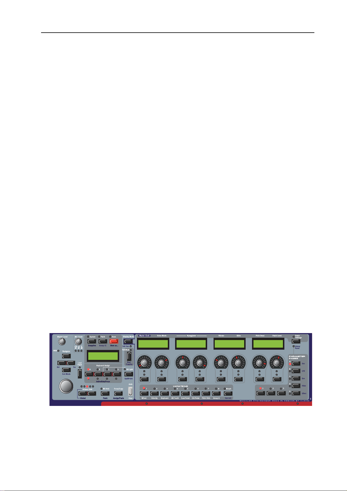
ACCESS MORE ASSIGNED PARAMETERS IN THE PATCH
To the bottom right of the front panel are 5+3
programmable P
also “Parameter pages” on page 19.
Pressing the A and the 2 buttons give access to
P
ARAMETER PAGE A2. Now, 8 new parameters are shown
in the A
SSIGNABLE DISPLAYS and you can edit them right
away. If you press the 3 button, another 8 parameters are
displayed. You can continue by pressing other combinations
to check out more assigned parameters. The P
AGES buttons are conveniently arranged in a way that you
P
can press two buttons simultaneously at once with two
fingers for super fast Page selection.
ARAMETER PAGES selection buttons. See
ARAMETER
LP_Filter1------|
Freq Res
LP_Filter2------|
Freq Res
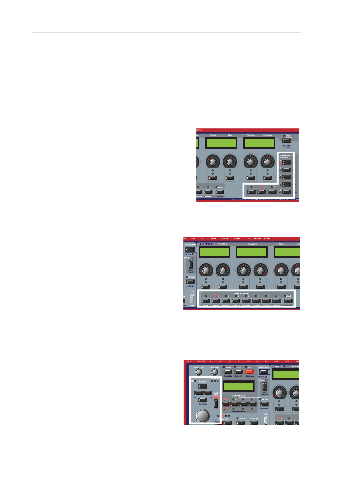
VARIATIONS
Below the 8 ASSIGNABLE KNOBS are 8 VARIATION
BUTTONS. See also “Variations” on page 17.
LEDs above the buttons show which VARIATION
The
is currently active. Select another V
pressing another V
ARIATIONS can be selected plus restored by pressing
V
S
HIFT plus the VARIATION button. This will restore
ARIATION button.
ARIATION by
EnvADSR1--------Attack Decay
the knobsettings to the same positions as when the
patch was loaded from memory.
This S
HIFT-VARIATION1-8 ‘select and restore’
function is indispensible when playing on stage, as it
undoes all the tweaks in an earlier played V
during a stage performance, S
HIFT-VARIATION1-8 gives you immediate and reliable control over what
ARIATION. If you go wild on expressively tweaking the sound
sound to play next, no matter the earlier tweaks you did on that sound.
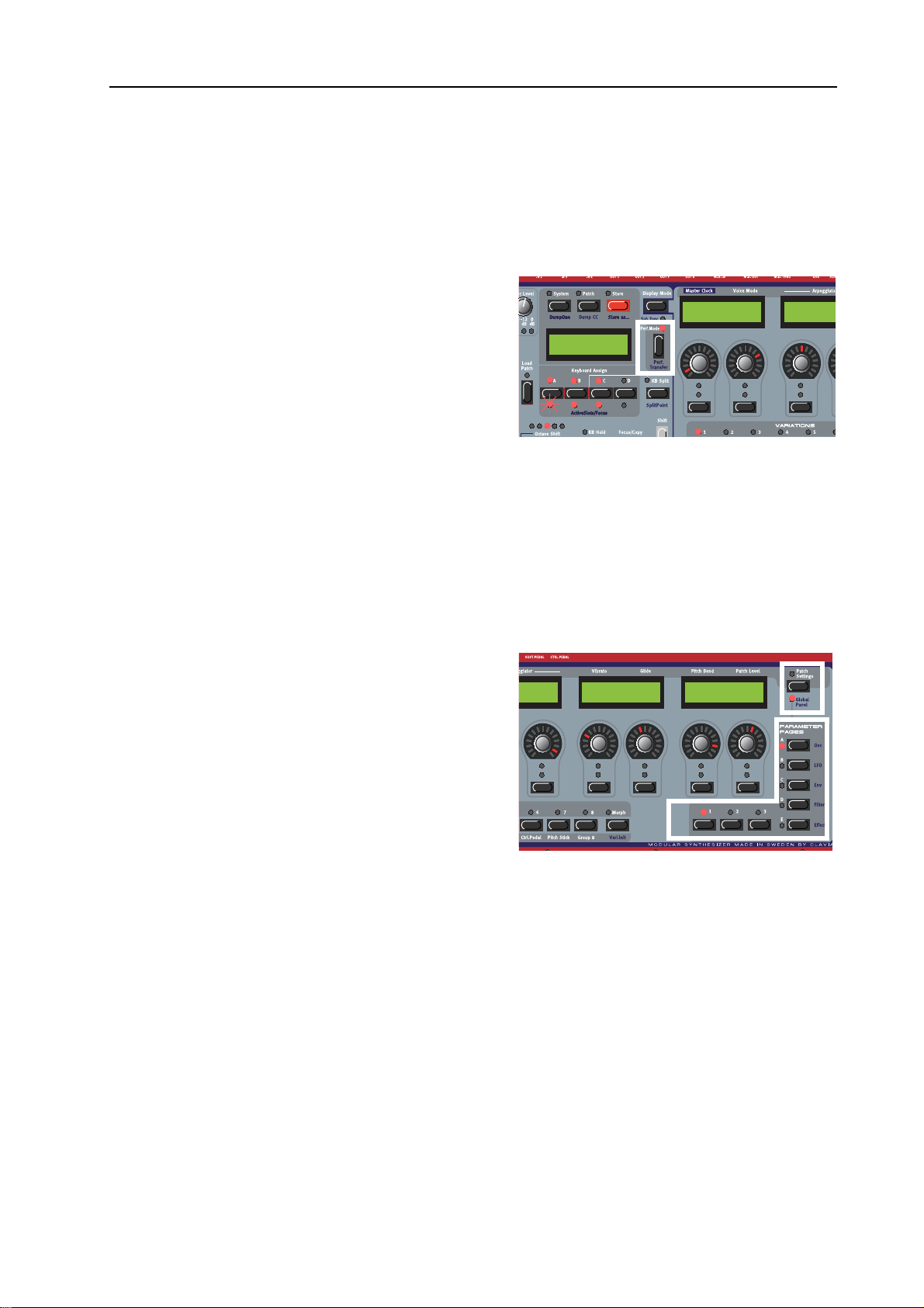
LOAD A NEW PATCH FROM THE INTERNAL MEMORY
Load a new Patch into the active Slot (Slot A in this
example) by first turning the R
the Patch. If you like you can also switch between
Banks by pressing the U
button. Load a Patch into the Slot by first turning the
R
OTARY DIAL to select the Patch, then press the
ATCH LOAD button to load and activate the Patch
P
for play. Now, you can try out other Patches from the
OTARY DIAL to select
P/DOWN NAVIGATOR
1:2 Synth
Dream synth
----------------|
Sustain Release
EnvFilter1----Attack Dec
EnvADSR1------Attack Deca
Page 22
Page 23
NORD MODULAR G2 V1.3x 2. Synth quick tour: Check out some Performances
-
internal memory banks, tweak the parameters knobs and check out different Variations as described
above.
Note that to be able to load individual Patches the Performance Mode
LED should be OFF.
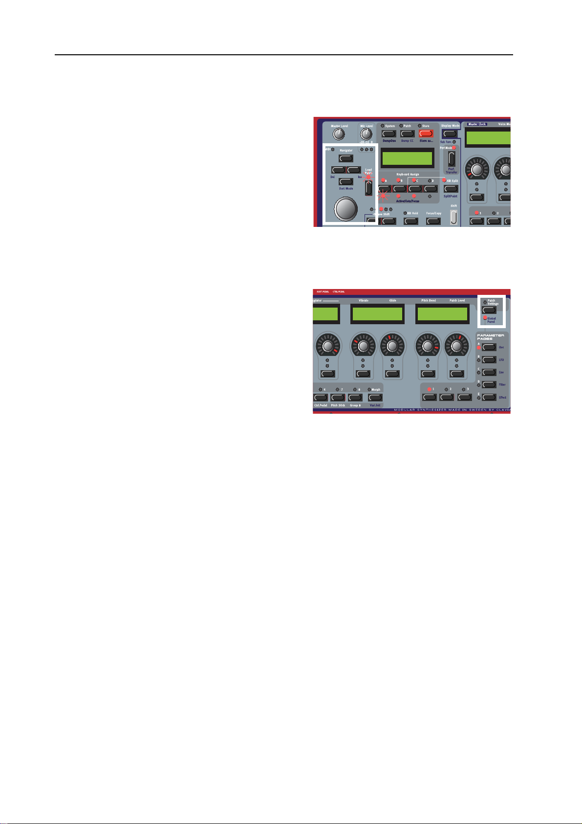
CHECK OUT SOME PERFORMANCES
A Performance is a combination of up to four Slots. See
also “Playing multitimbrally” on page 18 and
“Performances” on page 18.
Enter Performance mode by pressing the
P
ERFORMANCE MODE button (button LED lights
1:1
Welcome
up). Load a Performance into the Slots by first turning
the R
OTARY DIAL to select the Performance, then
press the P
Performance for play. As you can see, several S
LEDS are now lit to indicate that several Patches are used in the Performance. The Performance name is
shown in the M
A
SSIGNABLE DISPLAYS.
ATCH LOAD button to load and activate the
LOT
AIN DISPLAY and the first 8 parameters of the focused Patch are shown in the
Note that a Performance always loads in all four Slots, storing any previously loaded Patches in the Slots
in a temporary buffer, so changing back to Patch mode will reload those previously loaded Patches before
Performance mode was activated. Also note that in the loaded Performance not all Slots need to be
active. If a Slot
LED does not light up it simply indicates that this Slot is inactive.
OSC1------------|
Freq Fine
OSC2------Freq
ACCESS ASSIGNED PERFORMANCE (GLOBAL) PARAMETERS
Each Performance can have a separate set of GLOBAL
ARAMETER PAGES, in addition to the Parameter
P
Pages of each Patch in the Performance. See also
“Parameter pages” on page 19 and “Global
(Performance) Parameter Pages” on page 49.
Hold down S
button to access G
Alternatively you can ‘double click’ the P
S
ETTINGS button. Now, 8 new parameters are shown
in the A
If you go to the P
HIFT and press the PATCH SETTINGS
LOBAL PARAMETER PAGE A1.
ATCH
SSIGNABLE DISPLAYS and you can edit them.
AGE A2, another 8 Performance
parameters are displayed, and so on. If you want to access the Programmable Parameter Pages of each
individual Patch, hold down S
‘double click’ the P
Slot is shown in the A
ATCH SETTINGS button. Now, the first Parameter Page of the Patch in the focused
SSIGNABLE DISPLAYS.
HIFT and press the PATCH SETTINGS button again. Alternatively you can
This means that a total of 600 knob assignments can be stored in a Performance, 120 for each Slot plus
and extra 120 in the Global pages. The assignments in the Global pages can be a mix of module knob
assignments from all four Slots. Note that globally assigned knobs do not have to be previously assigned
in the individual Slot pages themselves.
--------|
Release
A:Filter2-------|
Freq Res
B:OSC2----------|
Freq Fine
Page 23
Page 24
2. Synth quick tour: Check out some Performances NORD MODULAR G2 V1.3x
y
LOADING ANOTHER PERFORMANCE FROM THE INTERNAL MEMORY
Load another Performance into the Slots by first
turning the R
Performance. If you like you can also switch between
Banks by pressing the U
OTARY DIAL to select another
P/DOWN NAVIGATOR
1:2
Scream synth
A:EnvADSR1----Attack Deca
button. Then load the selected Performance into the
Slots by pressing the P
ATCH LOAD button. Now, you
can try out other Performances of the internal memory
and edit parameters as described above.
To revert to “Patch mode”, press the P
ODE button. If the PERFORMANCE MODE LED
M
OFF you’re back in Patch Mode.
turns
ERFORMANCE
CHANGING VARIATIONS WHEN IN GLOBAL PANEL MODE
Changing VARIATIONS differs for when the G2 is in
ATCH PANEL mode where the ASSIGNABLE
P
NOBS/DISPLAYS show Parameters from the active
K
Slot, or when the G2 is in G
LOBAL PANEL LED lights up), where the
G
SSIGNABLE KNOBS/DISPLAYS can show a mix of
A
LOBAL PANEL mode (the
Parameters from all Slots/Patches.
When in G
ARIATION with one of the VARIATION buttons will
V
LOBAL PANEL mode, selecting another
cause all active Slots to switch to this selected
V
ARIATION. However, when the G2 is in PATCH
ANEL mode (the GLOBAL PANEL LED is dimmed), selecting another VARIATION will only change the
P
ARIATION for the focused Slot.
V
--------|
Release
A:Filter2-------|
Freq Res
B:OSC2----------|
Freq Fine
Page 24
Page 25
NORD MODULAR G2 V1.3x 3. Working with the synth: Check out some Performances
3. WORKING WITH THE SYNTH
This chapter refers to the G2 Keyboard and G2X models. If you have a G2 Engine model you can
still read this chapter if you desire to do so, as virtually all described G2 Keyboard and G2X panel
functions are also available as ‘soft’ functions in the Editor program.
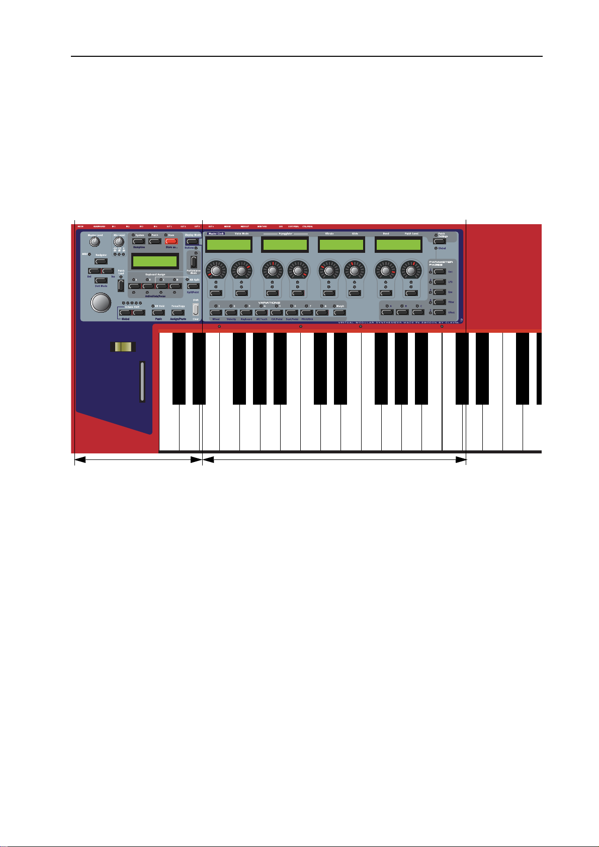
NORD MODULAR G2 AND G2X FRONT PANEL
System Functions section
The frontpanel is divided in two sections, the SYSTEM FUNCTIONS section at the left side and the
OUND FUNCTIONS section at the right side.
S
In the S
multitimbral play and layering of sounds, edit system default settings,
settings changes you make in this section will be immediately memorized by the G2 and when the G2 is
powered up it will use the settings that where last made before the G2 was powered down.
In the S
This S
in a sound. A modular system can have many knobs to tweak, much more than the eight physical knobs
and buttons located under the four displays. The G2 uses a clever paging system named P
P
definitive, the sound can be stored in the G2 sound memories. Use the Store function in the System
Functions section to save your tweaks.
YSTEM FUNCTIONS setting you can recall sounds from the G2 sound banks, change modes for
OUND FUNCTIONS section you can make edits to the sound or sounds you are currently playing.
OUND FUNCTIONS section is designed to give you easy access to all tweakable knobs and buttons
AGES to access up to 120 tweakable parameters in a single sound. To make the changes to a sound
Sound Functions section
MIDI settings, etc. All system
ARAMETER
Page 25
Page 26
3. Working with the synth: System Functions section NORD MODULAR G2 V1.3x
SYSTEM FUNCTIONS SECTION
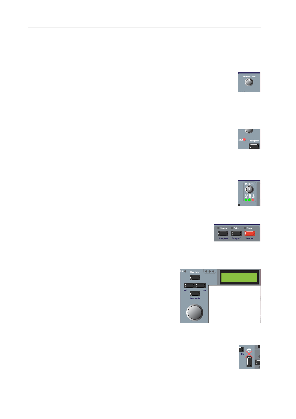
MASTER LEVEL
The MASTER LEVEL knob controls the output level of all four OUT jacks and the
EADPHONES output. Use this knob to set the overall volume level of your instrument or
H
set the sound level when using headphones.
Tip! The Master Level knob does not send or receive any
used to control the entire instrument’s output level. To affect the volume of an individual Patch through
MIDI (.e.g. from a sequencer track), you can use MIDI CC#7, which is hardwired to the Patch Gain knobs
in the respective Slots (see more about this on “Patch Level” on page 62).
MIDI LED
The MIDI LED indicates incoming MIDI Note, MIDI CC# and MIDI SYSEX messages on any
MIDI channel. MIDI messages on any of the Slot’s MIDI Channels and/or the Global MIDI
Channel are indicated by long
LED blinks. Long LED blinks means that there should most probably be sound, and
short
short
LED blinks mean that there is MIDI information received but ignored, as this information is not in
MIDI channels the Slots are ‘listening to’.
LED blinks. Messages on other MIDI Channels are indicated by
MIDI CC# information, but is only
MIC LEVEL
The MIC LEVEL knob controls the XLR microphone input preamp level. Below the MIC
L
EVEL knob are three LEDS which show the input level of the dynamic microphone
connected to the XLR I
will indicate the input level of the line level signal routed to the I
IC LEVEL knob only affects the XLR INPUT - not the IN 1 input.
the M
NPUT on the rear panel. If you don’t use a mic, the LEVEL LEDS
N 1 input instead. Note that
SYSTEM, PATCH AND STORE BUTTONS
Above the MAIN DISPLAY are the SYSTEM (see “Edit System Settings” on
page 29) and P
ATCH (see “Acessing (Edit) any Parameter in a Patch” on page 37)
buttons which can be used to enter all system and Patch related menus. The
S
TORE button (see “Store a Patch” on page 40 and “Storing a Performance” on
page 50) is used for storing Patches and Performances.
NAVIGATOR BUTTONS, ROTARY DIAL AND MAIN DISPLAY
Below the MASTER LEVEL knob is a set of four buttons, the
N
AVIGATOR buttons. These are used to navigate in the MAIN
ISPLAY and to select different functions. Below the
D
AVIGATOR buttons is the ROTARY DIAL. With the ROTARY
N
D
IAL you can select Patches and Performances, enter various
kind of data etc.
Note that the functions for the N
R
OTARY DIAL and the MAIN DISPLAY will change when the G2
AVIGATION BUTTONS, the
is set to a different mode. Modes can be changed by pressing
either the S
YSTEM, the PATCH, the STORE or the PERFORMANCE MODE button.
LOAD PATCH
Press this button when you want to load a selected Patch or Performance into the focused
Slot/Slots (see “Search for and load a Patch” on page 36 and “Load a new Performance from
the internal memory” on page 48).
Page 26
Page 27
NORD MODULAR G2 V1.3x 3. Working with the synth: System Functions section
SLOT BUTTONS
Below the MAIN DISPLAY are the four SLOT buttons (A, B, C and D). You can
load one Patch in each of the Slots at a time. See “Sound Functions section” on
page 33, “Activate several Slots” on page 43 and “Creating a Performance” on
page 48 for info on how to use the Slots.
OCTAVE SHIFT BUTTONS
With these buttons you can either transpose a Patch in a Slot or transpose the whole
Keyboard globally over a range of +/-2 octaves.
In Patch Transpose mode, the O
individually. In this mode the keyboard itself is not transposed. The Patch transposition
takes effect immediately. In Patch Transpose mode only one of the five
When pressing S
HIFT plus the left OCTAVE SHIFT button the LEDs will invert, meaning that all LEDs but
one light up. This puts the octave shift controls in Global Octave Shift mode which will transpose the
keyboard globally instead of only the Slot. When in Global Octave Shift mode all Slots will be transposed
equally. The notes played on the keyboard that are send as
the synth will also be transposed, meaning that in this mode the G2 keyboard acts like a Master Keyboard.
KB HOLD/PANIC
Press the KB HOLD button to make every note or chord you play sustain until you press
any new keys. The Keyboard Hold function is also very useful together with the
Arpeggiator (see “Arpeggiator” on page 35). If notes should hang or the synth should
behave strange, press S
HIFT+KB HOLD to send an internal ALLNOTESOFF to the synth.
CTAVE SHIFT buttons transpose each of the Slots
LEDs will light up.
MIDI NoteOn through the MIDI OUT jack of
THE FOCUS/COPY/(ASSIGN/PASTE) BUTTON
To the right below the MAIN DISPLAY section you find the FOCUS/COPY button. This
button can be used in many situations, for example when you want to copy & paste
various things and also when you assign parameters to Parameter Pages. Holding
S
HIFT+FOCUS/COPY alternates the functionality to Assign/Paste.
PERFORMANCE CONTROLS
Below the MAIN DISPLAY section you find the performance controls: the PITCH
TICK and MODWHEEL. The PITCH STICK can be used to control pitch bend (see
S
“Bend” on page 35) as well as an entire Morph group. The M
ODWHEEL can control
Vibrato (see “Vibrato” on page 35) and also a separate Morph group. See “Morph
groups” on page 44 for info on how to use these controls with Morph groups.
G2X GLOBAL MODWHEELS
The Nord Modular G2X model features two extra GLOBAL MODWHEELS. These
wheels can control extra modulations. The G
LOBAL MODWHEELS are hardwired to
Morph groups 5 & 8 and can control any parameter in a Patch through these Morph
groups. See “Morph groups” on page 44 for info on how to use these controls with Morph groups.
N
OTE! In contrast to the standard Modwheel these two extra Modwheel are not affected by the keyboard
focus, meaning that they also work in Patches played from external
MIDI signals.
Page 27
Page 28
3. Working with the synth: System Functions section NORD MODULAR G2 V1.3x
DISPLAY MODE
This button lets you switch between two different display modes for
SSIGNABLE DISPLAYS. By default, the ASSIGNABLE
the A
D
ISPLAYS show module names and parameter names. When you
turn an A
the parameter name is temporarily replaced by the parameter
value. In the other display mode, the parameter names and values
are constantly displayed. However, the module names are not
shown in this mode. Think of the Display having to show three
lines of text, where the display mode lets you choose to see either
lines 1 & 2 or see lines 2 & 3.
KB SPLIT MODE
Lets you split the keyboard and play/control Slots from a left hand and a right hand keyboard zone. The
two left most Slots A and B will be assigned to the left hand keyboard zone, while the two Slots C and
D will be assigned to the right hand keyboard zone. The split point can be altered by pressing the KB
S
PLIT button while holding the SHIFT button. Repeating SHIFT/KB SPLIT will move the keyboard split
point. The
It is possible to make more advanced keyboard split settings through the system menu, see “Keyboard
Split” on page 49 and “Keyboard Zone |Pe” on page 32.
SSIGNABLE KNOB or press an ASSIGNABLE BUTTON,
FltNord1--------|
Freq Res
Freq Res
622.5Hz 1.72
LEDs directly above the keyboard show the current split point.
SUB FUNC
Hold SHIFT and press the DISPLAY MODE button to go into SUB FUNC mode and display the names
of button parameters instead of knob parameters in the A
have assigned combined knob+button parameters to the A
SSIGNABLE DISPLAYS. This is useful when you
SSIGNABLE DISPLAYS.
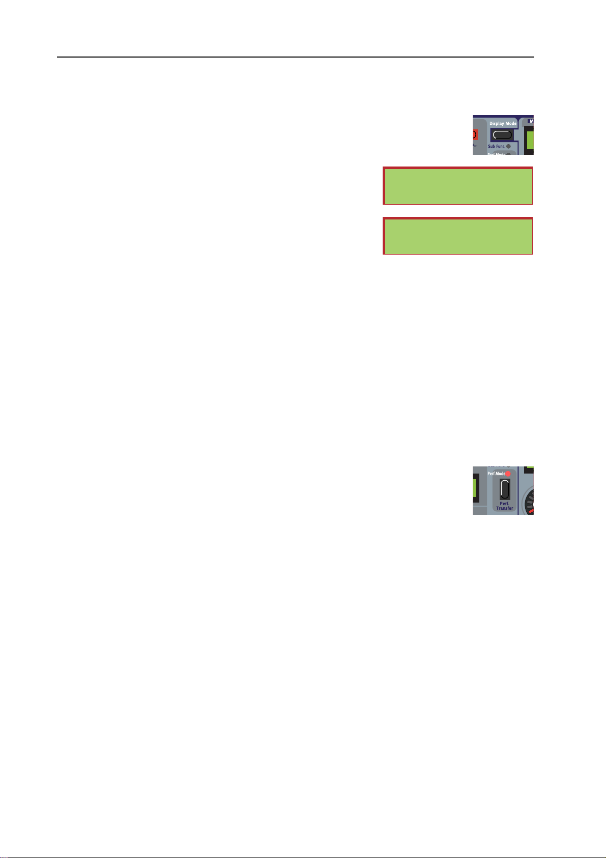
PERFORMANCE MODE
In Performance mode you can create Keyboard Split/Layers configurations of up to 4
Slots. In Performance mode Pathes loaded to the four Slots can be saved and recalled
together as a single Performance (file). See “Performances” on page 47. When the
Performance button
LED lights up it indicates the G2 is in Performance mode. If the LED
is dimmed it indicates the G2 is in Patch mode.
SWITCHING BETWEEN PATCH AND PERFORMANCE MODES
Patch Mode and Performance Mode are completely separate modes, each with its own separate buffer
to hold the Patches loaded in all Slots for that mode. This means that when changing to Performance
mode, all Patches loaded in the four Slots in Patch Mode remain in their buffer. Switching back to Patch
Mode will automatically bring up those four original Patches from the Patch Mode buffer again. Note
that this ‘double buffering’ allows you to have up to eight Patches instantly standby, four Patches in
Performance mode and four Patches in Patch mode. Simply pressing the P
ERFORMANCE button allows
you to switch between these two sets of up to four Patches.
COPYING PATCHES BETWEEN PATCH AND PERFORMANCE MODES
Holding the SHIFT button while pressing the PERFORMANCE button will ‘transport’ a copy of the
Patches to the other mode. This will overwrite the temporary Patch buffers for the Patch and the
Performance modes. While in Patch mode, pressing S
HIFT-PERFORMANCE will transfer a set of up to
four Patches into a new Performance, which can then be stored as a Performance in the Performance
memory banks. While in Performance mode, pressing S
HIFT-PERFORMANCE will ‘separate’ the
Performance into individual Patches to be played or edited in Patch mode.
Page 28
Page 29
NORD MODULAR G2 V1.3x 3. Working with the synth: Edit System Settings
y
y
y
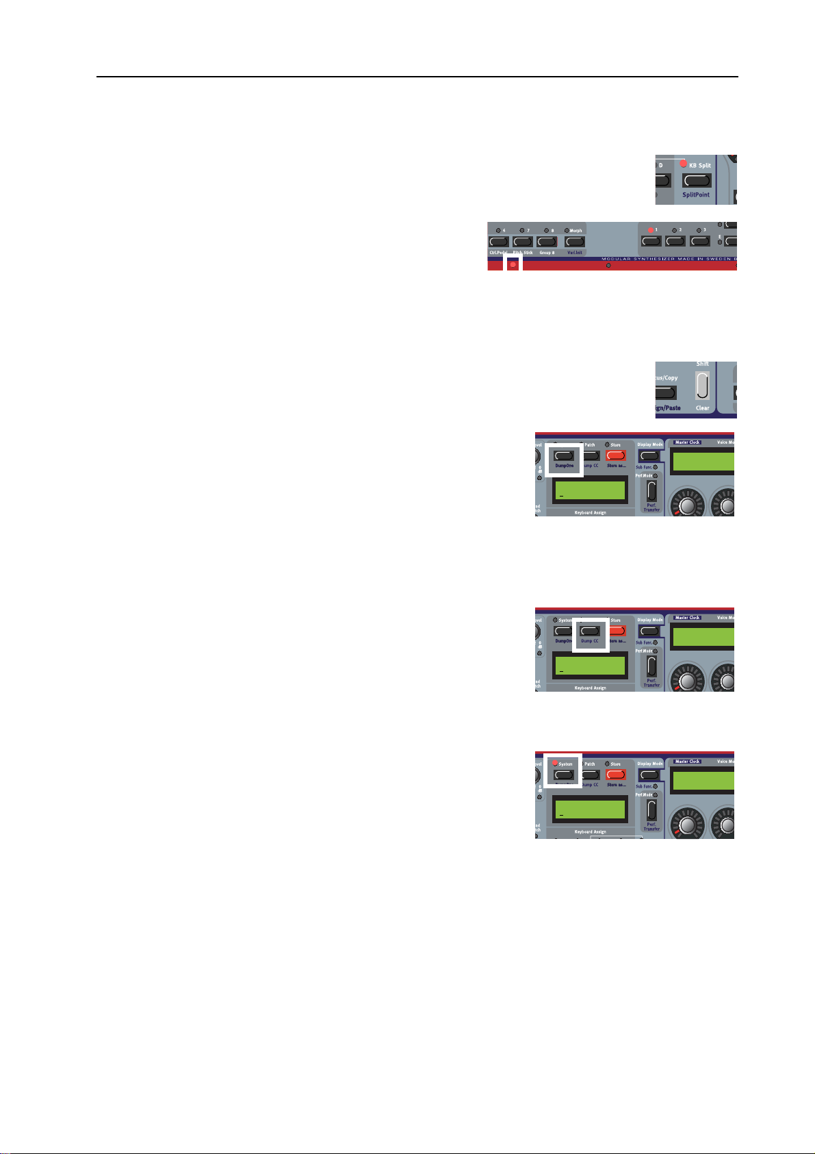
KB SPLIT MODE/SET SPLIT POINT
Lets you split the keyboard and play/control different Slots from different keyboard
zones. See “Keyboard Split” on page 49.
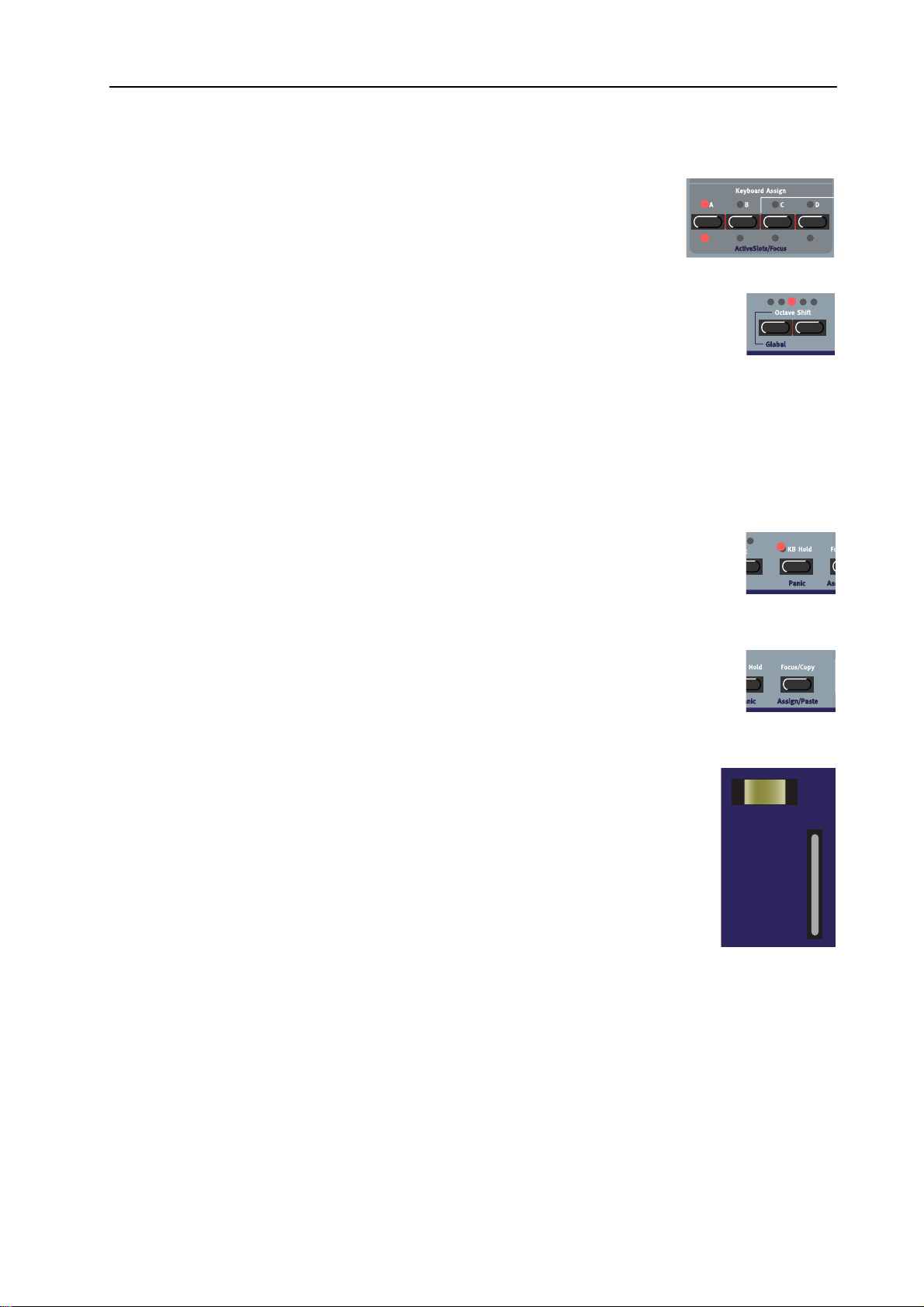
KEYBOARD SPLIT LEDS
Above the keyboard are four Keyboard Split LEDs which
indicate current keyboard split position in Keyboard Split
mode (see “Keyboard Split” on page 49). These
light up if the Keyboard Split is set up through the KB Split
function on the front panel of the G2 Keyboard and G2X models. See also “Activate several Slots” on
page 43 and “Layering Patches” on page 43.
THE SHIFT/CLEAR BUTTON
The SHIFT button is used to activate functions printed below some buttons on the front
panel. It’s also used for deleting entire Morph groups and for clearing Variations.
DUMP ONE
Hold down SHIFT and press the SYSTEM button to send a MIDI
SYSEX dump of the Patch in the focused Slot, or of an entire
Performance in Performance Mode. Note that an average
SYSEX dump of a Patch is approximately 5 kB and that of a
Performance nearly 20 kB. This means the recording device - a
sequencer, for example - must be prepared for this amount of data.
It takes a
MIDI cable about one second to transfer 3kB of data, so it might take up to seven seconds before
a Performance Dump is completed. See also “G2 MIDI System Exclusive Specification” on page 132.
LEDs only
MIDI
Sustain |Pa
On
ADSR-Env1
Attack Deca
DUMP CC (SEND CONTROLLER SNAPSHOT)
Hold down SHIFT and press the PATCH button (DUMP CC) to
send the values of all
MIDI CC# controllers used in the Patch in the
active Slot. See also “MIDI SendCtrl |Pa” on page 31, “MIDI
Controllers” on page 127 and “MIDI Automation” on page 128.
Sustain |Pa
On
EDIT SYSTEM SETTINGS
Press the SYSTEM button to access the system parameters and
functions. The System menu is divided into three types of
parameters:
1. System parameters, which are global for the entire synth (indicated in the DISPLAY by ‘|SY’ in the upper right corner).
Note that changing System parameters has an effect at the ‘top level’ of the synthesizer, meaning
that they will affect all Slots equally.
2. Patch parameters, which are unique for the currently focused Patch (indicated in the DISPLAY by
A’ in the upper right corner)
‘|P
Note that as changing a Patch parameter will only have an effect on the currently focused patch you
will have to first select the Patch you want to apply a change to with the Slot buttons. You can do
this by simply pressing the Slot button the Patch is in.
Sustain |Pa
On
ADSR-Env1
Attack Deca
ADSR-Env1
Attack Deca
Page 29
Page 30
3. Working with the synth: List of functions in the G2 System menu NORD MODULAR G2 V1.3x
3. Performance parameters, which are unique for the currently active Performance (indicated in the
ISPLAY by ‘|PE’ in the upper right corner)
D
Note that some Performance parameters are actually a group of parameters for the Slots used in the
Performance. The setting for each Slot can be different to that of the other Slots. Just like with the
Patch parameters, you can select a Slot by pressing its Slot button and them change the Performance
parameter for that particular Slot. But note that the settings for all the Slots used in the performance
are actually saved in the Performance and not in the individual Patches.
Select a function with the DOWN NAVIGATOR button.
LIST OF FUNCTIONS IN THE G2 SYSTEM MENU
MASTER TUNE |SY
Use this function to transpose the keyboard in semitones and/or fine
tune the synth to other instruments or already recorded tracks. The
transposition range is from -6 to +6 semitones and is set with the
R
OTARY DIAL.
Note that if you want to transpose up from A to Bes you just go one semitone up. If you would need to
transpose down from A to E you will have to go 5 semitones down, so the display shows ‘-5 semi’.
Transposing down from A to D is done by first transposing 5 semitones up and additionally set the
Global Octave Shift for the keyboard one octave down with the Octave Shift buttons. This results in a
total transposition of seven semitones down.
Fine adjustment ranges from -100 to +100 cents. 100 cents is one semitone. All Oscillator and Filter
modules that are set to track the keyboard are affected by the Master Tune function. Select the fine tuning
amount with the R
OTARY DIAL.
Master Tune |Sy
semi 0 cent
0
MIDI LOCAL |SY
Turn the MIDI Local Control On or Off. Select Local On to be able
to control the synth from the internal keyboard and the pedals.
data is also transmitted via the
the keyboard and pedal actions are transmitted only via
MIDI OUT jack. In the Local Off mode,
MIDI and do
MIDI Local |Sy
MIDI
n
O
not play the synth itself.
Local Off is a function found on almost all
Imagine that the
IN jack. Now imagine that you play a note on the keyboard to play a sound on the synth, and this note is
also send out through
MIDI OUT jack of the synthesizer is routed back, via the external sequencer, to the MIDI
MIDI to the sequencer. If the sequencer ‘echoes’ this note back to the synth, the
note will be played a second time, now from the
MIDI Local Off will prevent this, as in this mode only the ‘echoed’ note will sound. This way you can also
be sure that the sequencer did actually receive the played note.
setting named
ECHO that will set if the sequencer will or will not retransmit the received notes back. So,
you will have to check the sequencer as well when making a change to this
MIDI synthesizers and is used with external MIDI sequencers.
MIDI IN jack, which in general does not sound good.
MIDI sequencers do in general have a
MIDI Local setting.
MIDI SLOT CH |SY
Set the MIDI channel for each SLOT (A-D). The set channels will be
used for receiving and transmitting
Slot will not receive or transmit any
S
LOT button and set MIDI channel with the ROTARY DIAL. Then,
MIDI data. If you select ‘Off’, the
MIDI data at all. Press desired
MIDI Slot Ch |Sy
1
234
Page 30
Page 31

NORD MODULAR G2 V1.3x 3. Working with the synth: List of functions in the G2 System menu
repeat the procedure for the other Slots by pressing the corresponding SLOT buttons. Note that in
Performance Mode, the internal keyboard will send on all Slot’s
MIDI GLOB CH |SY
Here you set the Global MIDI Channel for the synth. The Global
MIDI Channel should be used for receiving MIDI note data and
control data (Modwheel, Aftertouch, Velocity, Aftertouch and
Pedals) if this data needs to be played by all Slots, no matter the
channel they are in. The Global
Program Change messages in Performance mode. Select Global
Range: Channel 1-16, Off. See also “MIDI Global Channel” on page 126.
MIDI CLK SEND |SY
Here you choose whether or not to send out MIDI Clock to the MIDI
OUT jack of the synth. Sending out a MIDI Clock signal will only work
when you use the internal Master Clock as clock source. Select On or
Off with the R
MIDI CLK RECV |SY
Here you choose whether or not to accept external MIDI Clock
signals received on the
set to ‘On’, the Master Clock of the G2 will automatically sync to any
incoming
OTARY DIAL.
MIDI IN connector at the back of the G2. If
MIDI Clock. Select On or Off with the ROTARY DIAL.
MIDI Channel should also be used for sending and receiving MIDI
MIDI channels that have Keyboard Assign.
MIDI Glob Ch |Sy
6
1
MIDI
MIDI Channel with the ROTARY DIAL.
MIDI Clk Send |Sy
ff
O
MIDI Clk Recv |Sy
ff
O
MIDI PRG CHNG |SY
Here you select how the synth should handle Program Change and
Bank Select (
Receive (only) and Send and Receive with the R
MIDI CTRL |SY
Here you select how the synth should handle MIDI CC# messages.
Select Off, Send (only), Receive (only) and Send and Receive with the
R
OTARY DIAL.
MIDI SENDCTRL |PA
This function lets you send the current values of all the MIDI CC#
controllers that are used in a patch to the
the back of the G2. This function can be used to record all current
MIDI CC# values to one position in a song on a MIDI sequencer or
MIDI recording software. Note that it takes a little time to send all MIDI CC# values.
When the G2 is controlled by an external
is connected to the
current values of the knobs and sliders on the
a variation change is initiated from the G2 panel. Alternatively, the
programmed to send a SysEx command to the G2 to initiate this function each time a variation change
is initiated from the
Press the rightmost (Ins) Navigator button to start the transmission over the
function can also be activated by holding down S
MIDI CC# 32) MIDI messages. Select Off, Send (only),
OTARY DIAL.
MIDI OUT connector on
MIDI controller device and the MIDI OUT at the back of the G2
MIDI IN of the controller device, this function can be used to instantly refresh the
MIDI controller. Using this function is often necessary after
MIDI controller device. See also “1.5 All Controllers Request” on page 134.
HIFT and pressing the PATCH button (DUMP CC).
MIDI Prg Chng |Sy
end & Receive
S
MIDI Ctrl |Sy
end & Receive
S
MIDI SendCtrl |Pa
Press > to send
MIDI controller device can be
MIDI OUT connector. The
Page 31
Page 32

3. Working with the synth: List of functions in the G2 System menu NORD MODULAR G2 V1.3x
MIDI SYSEX ID |SY
Here you can set an ‘Instrument SysEx ID’. This is very useful if
you’re sending SysEx dumps of sounds from a sequencer to the
Nord Modular G2 and have several G2 synthesizers
Let’s say you have two G2 synthesizers. These two instrument
models have the same ‘Manufacturer ID’ and ‘Model ID’ in the SysEx protocol. By defining separate
SysEx ID’s on each of the two synths, you will be able to “direct” the SysEx dumps from the sequencer
to one of the G2’s while the other one will ignore the dumps. Just make sure that you define a separate
SysEx ID before dumping the sounds to the sequencer. Select Instrument SysEx ID with the R
D
IAL. Range: 1-16, All. See also “G2 MIDI System Exclusive Specification” on page 132.
SUST PED POL |SY
Different sustain pedals use different polarity to activate the sustain
switch. Select between ‘Open’ and ‘Closed’ with the R
CTRL PED GAIN |SY
Different control/expression pedals have different characteristics.
Here you can select Gain to adjust the control pedal functionality of
the synth to your specific expression pedal. Select range (x1.00-x1.50)
with the R
OTARY DIAL.
MIDI connected.
OTARY DIAL.
MIDI SysEx ID |Sy
6
1
OTARY
Sust Ped Pol |Sy
pen
O
Ctrl Ped Gain |Sy
.00
x1
MEMORY PROT |SY
Select memory protection for the entire internal Patch and
Performance memory. Select On or Off with the R
KEYBOARD ZONE |PE
Here you can set individual note ranges for each of the Slots in a
Performance. Press desired S
with the R
set the highest note limit with the R
procedure for the other Slots by pressing the corresponding S
overlapping keyboard zones. Note that these ranges are also affected by any Keyboard Split setting you
have in your Performance (see “Keyboard Split” on page 49). When you store your Performance, these
settings will be stored with it.
SUSTAIN PEDAL ON/OFF |PA
Select if you want the Sustain Pedal functionality on or off in the
Patch. If set to On, a connected sustain pedal will control both
sustain and any parameters assigned to the Switch Morph group.
Select On or Off with the R
VIBRATO RATE |PA
Select Vibrato Rate for the Patch. Range: 4.00-8.00 Hz. (The Vibrato
Amount is set in the Patch Settings “menu” for the Patch. See
“Editing Patch Settings” on page 34).
OTARY DIAL. Press the RIGHT NAVIGATOR button and
LOT button and set lower note limit
OTARY DIAL. Then, repeat the
OTARY DIAL.
OTARY DIAL.
LOT buttons. It’s also possible to have
Memory Prot |Sy
ff
O
Keyboard Zone |Pe
- B3
C-1
Sustain Pedal |Pa
n
O
Vibrato Rate |Pa
.02 Hz
6
SYNTH NAME |SY
Here you can name your synth. Select characters with the ROTARY
D
IAL and change the “cursor” position with the left/right
AVIGATOR buttons. Alternatively, press and hold the DOWN
N
Page 32
Synth Name |Sy
odularG2
M
Page 33

NORD MODULAR G2 V1.3x 3. Working with the synth: Sound Functions section
-
NAVIGATOR button and select letters with the ROTARY DIAL. Each time you release the DOWN
AVIGATOR button the cursor in the DISPLAY advances one step. Repeat the procedure for the entire
N
Synth name. If you want to delete a letter/position and thus move all the letters to the right of the cursor
one step back, hold down S
HIFT and press the LEFT NAVIGATOR (DEL) button. (This function is the
same as using the Delete key on a computer keyboard.) If you want to move all letters to the right of the
cursor one step forward and thus make room for more letters, hold down S
N
AVIGATOR (INS) button.
HIFT and press the RIGHT
SOUND FUNCTIONS SECTION
ASSIGNABLE KNOBS AND BUTTONS WITH DISPLAYS
Module parameters in a Patch can be assigned freely to any
of the 8 A
SSIGNABLE DISPLAYS. These knobs are designed to be
A
SSIGNABLE KNOBS or BUTTONS below the four
the main controls to tweak the sound of a Patch. See also
“Assignable Knobs/Buttons” on page 19 and “Acessing
(Edit) any Parameter in a Patch” on page 37 .
EnvADSR1--------Attack Decay
----------------|
Sustain Release
EnvFilter1----Attack Decay
PARAMETER PAGES BUTTONS
To the right are 8 PARAMETER PAGE selection buttons.
Select one of the 15 available P
pressing a
ROW and a COLUMN button. See “Parameter
ARAMETER PAGES by
pages” on page 19. See also “Acessing (Edit) any Parameter
in a Patch” on page 37 and “Global (Performance)
Parameter Pages” on page 49 for info on how to use these
pages.
VARIATION/MORPH BUTTONS
There are 8 VARIATION buttons with which you can
Attack Decay Sustain Release Attack Decay
select up to eight different Patch Variations (complete
parameter setups) within each Patch (see “Patch
parameter Variations” on page 39).
In Morph Mode, these 8 buttons double as Morph group
selection buttons to set Morphing ranges when you want to
control several parameters in a Patch from a single
controller source (see “Morph groups” on page 44).
PATCH SETTINGS/GLOBALPANEL
This button is used when you want to switch the four
parameter displays between either showing the Patch
parameters, which are printed above the A
D
ISPLAYS (see “Editing Patch Settings” on page 34), or the
ARAMETER PAGES (see “Acessing (Edit) any Parameter in a Patch” on page 37)
P
Pressing S
HIFT+PATCH SETTINGS or ‘double click’ PATCH SETTINGS to enter the GLOBAL PANEL
SSIGNABLE
50 cnt 1.0 s
Off Off
mode (see “Global (Performance) Parameter Pages” on page 49).
2 semi -7.3 dB
On MuteOff
Page 33
Page 34

3. Working with the synth: Editing Patch Settings NORD MODULAR G2 V1.3x
EDITING PATCH SETTINGS
1:1 Bass
120 BPM 14 (16)
Stop Poly
1/16 Rnd
Off 1 Oct
50 cnt 1.0 s
Off Off
2 semi -7.3 dB
On MuteOff
Press the PATCH SETTINGS button to the top right of the panel so the button LED lights up. This mode
displays basic Patch settings for the Patch. The parameter names are printed on the panel above each
A
SSIGNABLE DISPLAY and you can edit them by turning the ASSIGNABLE KNOBS and/or the
SSIGNABLE BUTTONS.
A
You can revert back to Patch Edit mode by pressing the P
ATCH button again so the button LED dims.
MASTER CLOCK
Set the Master Clock Rate with the corresponding Knob. Run/Stop the Master Clock with the
corresponding Button below the Knob.
The Master Clock can control several different functions:
4. It can be the MASTER MIDI CLOCK for your whole MIDI setup
5. It controls the Arpeggiator Speed
6. Several LFO modules can be controlled directly by the Master Clock
7. The Delay-time of some Echo Delay modules can be synced to the Master Clock
8. When several Slots are active they can all sync to and follow the current Master Clock rate, as the
Master Clock is global to the whole G2 system.
9. When the Master Clock is the MIDI MASTER CLOCK in your setup, the Run/Stop button will send out
MIDI START and MIDI STOP commands over the MIDI OUT connector. Note that the G2 system must
be set in the System menu to send
G2 system for the
MIDI MASTER CLOCK in your setup.
MIDI CLOCK commands over the MIDI OUT connector to use the
Sending MIDI CC#80 on the Global MIDI channel will also start/stop the Master Clock. This feature
is particularly useful when a G2 E
NGINE model is controlled by an external MIDI controller device.
10. If the G2 is set to receive MIDI CLOCK commands and a MIDI CLOCK signal is present on the MIDI IN
connector, this external
MIDI CLOCK will automatically take over and start to be the Master Clock.
The Arpeggiator, the LFO’s and the Delay modules set to Clk mode will now sync automatically to
the external
panel display and the endless knob that normally sets the tempo will become inactive.
MIDI CLOCK. The average tempo of the external MIDI CLOCK will be displayed in the
Note that an EXTERNAL MIDI CLOCK signal must be stable and ‘jitter free’ for reliable control of the
delay time on delay modules.
VOICE MODE
Set requested polyphony with the Knob (2-32 voices). The actual polyphony is displayed together with
the requested polyphony within parenthesis. Actual polyphony depends on the complexity of the loaded
Patches and how many Slots are loaded and active (Slot
LEDs light up).
Page 34
Page 35

NORD MODULAR G2 V1.3x 3. Working with the synth: Editing Patch Settings
Select Voice Mode (Poly, Mono or Legato) with the Button below the Knob. In Legato mode, the
Envelope modules do not retrigger when you play in a legato fashion, i.e. when you play a new key before
releasing the previous key.
ARPEGGIATOR
Select Period (note length/sync division rate) for the Arpeggiator in relation to the Master Clock rate with
the Knob. Run/Stop the Arpeggiator with the Button below the Knob. Note that the Master Clock has to be
active for the Arpeggiator to run. Select Direction with the right Knob and Range with the Button below the
Knob. If you want the Arpeggiator to continue when you release the keys, use the KB Hold function
described on “KB Hold/Panic” on page 27.
The Arpeggiator uses
MIDI SONG POSITION POINTER when synched to an external MIDI CLOCK, which
means that if you record the chords that control an arpeggio in an external sequencer, it will always play
back the pattern exactly the same way it played while recording the chord - even if you start the sequencer
in the middle of the sequence.
VIBRATO
This is a separate vibrato which affects all Oscillator modules in the Patch set to Keyboard Tracking. Set
the Vibrato amount, in cents of a semitone, with the Knob and select control source (Aftertouch,
Modwheel or Off) with the Button below the Knob. Set the Vibrato rate in the System menu described
on “Vibrato Rate |Pa” on page 32.
GLIDE
The Glide or portamento function is mainly intended for use in mono or legato Voice Mode (see above). The
glide characteristics can be described as “constant rate”. “Constant rate” means that the greater the
“distance” between two subsequent notes, the longer the glide time. Turn the Knob to adjust the glide
rate and press the Button to select glide mode. ‘Normal’ means the glide is always active and ‘Auto’ that
glide is active only when you play legato (you press a new key before you release the previous key). Range:
19 milliseconds per octave to 6.27 seconds per octave.
Note that if you use Glide in polyphonic mode, the glide will be unpredictable and perceived as more or less
random. This is because the glide is between voices rather than between keys. The glide will therefore be
from the available voices’ latest note values to the new notes rather than from the previously pressed
keys.
BEND
Set the Pitch bend range, in semitones, with the Knob. The pitch bend will affect all Oscillator modules
in the Patch set to Keyboard Tracking when you bend the P
ITCH STICK. Switch on/off the pitch bend
function with the Button below the Knob.
PATCH LEVEL
Set the total output level of the Patch with the Knob. Mute the output from the Patch by pressing the
Button below the Knob.
Page 35
Page 36

3. Working with the synth: Working with Patches NORD MODULAR G2 V1.3x
WORKING WITH PATCHES
LOAD A PATCH FROM MEMORY
Before loading a patch first check that the Performance
LED is OFF.
Press a S
LOT button to select the Slot in which to load
the Patch. Load the Patch into the Slot by first selecting
Bank (if necessary) with the U
buttons and then turning the R
P/DOWN NAVIGATOR
OTARY DIAL to select the
Patch. Load the selected Patch into the Slot by pressing
ATCH LOAD button. Note that every time you load
the P
a Patch into a Slot, there will be a brief moment of silence
when the Sound engine recalculates the Patch data
SEARCH FOR AND LOAD A PATCH
By default, when you load a Patch into a Slot, by first selecting Bank with the UP/DOWN NAVIGATOR
buttons and then turning the R
memory location number.
Note that you can change the sort/search mode to either ‘Alphanumerical’ or by ‘Category’.
OTARY DIAL and pressing PATCH LOAD, the Patches are displayed by
1:2 Synth
Dream synth
SEARCH FOR A PATCH IN ALPHABETICAL ORDER
By pressing the SHIFT + DOWN NAVIGATOR buttons
you will be able to load Patches in alphabetical order rather
than by memory location number. Select letter by
pressing the U
select Patch with the R
P/DOWN NAVIGATOR buttons and
OTARY DIAL.
SEARCH FOR A PATCH IN A SPECIFIC SOUND CATEGORY
By holding down SHIFT and pressing the DOWN
N
AVIGATOR button twice you will be able to load
Patches by Category rather than by memory location
number. The Patches within a Category will now be
displayed in alphabetical order. Select Category by
pressing the U
select Patch with the R
P/DOWN NAVIGATOR buttons and
OTARY DIAL.
CREATING A BLANK PATCH
D 1:2
Dream synth
Synth 1:2
Dream synth
This can only be done with the G2 EDITOR SOFTWARE and you will need a suitable Windows computer
or Macintosh OSX computer. Please refer to “Making your first patch” on page 63.
Page 36
Page 37

NORD MODULAR G2 V1.3x 3. Working with the synth: Working with Patches
ACESSING (EDIT) ANY PARAMETER IN A PATCH
Press the PATCH button above the MAIN DISPLAY.
Hold down S
button to get to the first module in the Voice Area
(VA) of the Patch. The module currently “in focus” in
the Patch will appear in the M
name and visual position in the Editor within brackets
[1:1] (first row, first column). These rows and columns
refer to how a Patch would show up on the computer
screen when the Editor program would be used.
The names of the modules should give you a clue on what they do
in a sound. Sometimes the clue is pretty clear, like when a module is named FltNord or OscA. Other times the name might
be obscure. If tweaking a knob in a module that you have no idea about what it is doing should give strange and unwabted
behaviour you can simply restore all tweaks in the Variation you’re in by pressing Shift and the current Variation button.
The first module’s (up to) eight parameters will appear in the A
change the values of the parameters by turning the A
UTTONS. Navigate to the next module by pressing the DOWN or RIGHT NAVIGATOR button or
B
turning the R
parameters can be found by pressing the 2 and 3 P
button and press the U
the Toolbar (Morph groups), Voice Area and the FX Area.
Note that all changes you make to parameters are only made in the current Variation you’re in right now.
The same parameter will not be affected in the other Variations.
HIFT and press the DOWN NAVIGATOR
AIN DISPLAY with its
SSIGNABLE DISPLAYS. You can now
SSIGNABLE KNOBS or pressing the ASSIGNABLE
OTARY DIAL. If a module should contain more than eight parameters, the remaining
ARAMETER PAGES buttons. Hold down the SHIFT
P/DOWN NAVIGATOR button to immediately change Patch Area focus between
Morphs
Play on the synth while
turning the A
NOBS to instantly hear what
K
SSIGNABLE
effects they have on the
PA [1:1]
MultiFilter1
MultiFilter1----Freq Freq M
----------------Res dB/Oct
----------------|
Bypass PWidth
sound. If the G2 system is
connected to a computer
running the Editor software,
the Editor will echo any
adjustments that you make from the synth front panel on the computer screen and vice versa. When
editing module parameters it can be useful to switch Display Mode (see “Display Mode” on page 28) to
constantly view the actual values of each parameter in the A
SSIGNABLE DISPLAYS. Some modules, like
Mixers with Mute buttons, have a combination of button+knob parameters assigned to each individual
control. By default, the A
parameter name instead, hold S
SSIGNABLE DISPLAY shows the knob parameter name. To view the button
HIFT and press the DISPLAY MODE button.
Note that while in Patch mode you have access to literally any knob/parameter in a Patch. In the factory
patches all sensible parameters are already assigned to A
SSIGNABLE KNOBS, so it hardly pays to use
Patch mode. But for the Patches that you made yourself, and probably know very well, Patch mode gives
you total control on literally everything that can be tweaked in your Patch.
ASSIGN PARAMETERS TO PANEL CONTROLS
It’s possible to assign nearly every module parameter in a Patch to a separate ASSIGNABLE KNOB or
SSIGNABLE BUTTON on the synth front panel. Do like this:
A
Page 37
Page 38

3. Working with the synth: Working with Patches NORD MODULAR G2 V1.3x
B
1. Press the PATCH button above the MAIN DIS-
PLAY to enter Patch Edit Mode (button LED lights
up). Hold down S
N
AVIGATOR button to get to the first module in
the Voice Area of the Patch.
2. Use the NAVIGATE buttons to ‘scroll’ to the module which contains the parameter you want to
assign. The module’s name and first parameters
are shown in the A
module contains more than 8 parameters, you can access the remaining parameters by pressing the 2
and 3 P
ARAMETER PAGES buttons.)
3. When you have found the module and parameter
you want to assign to an ASSIGNABLE KNOB or
A
SSIGNABLE BUTTON, hold down the FOCUS/
SSIGN button and turn the parameter KNOB (or
A
push the parameter B
parameter is a button). In this example we choose
the FltMulti1 Freq parameter.
Note that some modules, like Mixers with On/
Off buttons, have a combination of button+knob
parameters assigned to each individual control. If you
want to assign these types of “combination parameters” to an Assignable Knob and Button, you
have to copy the knob parameter and paste it by turning the Assignable Knob for the parameter combina
tion to be assigned properly.
HIFT and press the DOWN
SSIGNABLE DISPLAYS. (If a
UTTON if the module
Filter1
[1:1]
Morphs
FltMulti1-------Freq Freq M
----------------Res dB/Oct
-
4. Press the PATCH button or a PARAMETER PAGE button to exit Patch Edit Mode (PATCH button
LED dims) and revert to normal “play mode”.
5. Press the desired PARAMETER PAGES buttons to
get to the desired destination. You can choose
freely where to assign a parameter but it could be
convenient to use the P
ARAMETER PAGES group
names printed in blue on the front panel. Here,
we choose P
ARAMETER PAGE D1 (Filter).
6. Hold down the SHIFT and FOCUS/COPY buttons (Paste) and turn the ASSIGNABLE KNOB (or push the ASSIGNA-
BLE BUTTON) you want to assign the module parameter to. We
choose to assign the parameter to the first A
LED GRAPH around the ASSIGNABLE KNOB (or the ASSIGNABLE
B
UTTON LED) will light up with the pasted module parameter’s cur-
SSIGNABLE KNOB. The
s Bass TB
Bass
MultiFilter1
Freq
rent value and the parameter name will be shown in the corresponding
SSIGNABLE DISPLAY.
A
Page 38
Page 39

NORD MODULAR G2 V1.3x 3. Working with the synth: Working with Patches
7. If you want to assign more module parameters, press the PATCH button and repeat the procedure
from step 3 above. If you have assigned several parameters from the same module to adjacent
SSIGNABLE KNOBS/BUTTONS in a PARAMETER PAGE, the module name will only be shown for
A
the first parameter. There will be dashes in the A
SSIGNABLE DISPLAYS to indicate that the following
parameters are from the same module.
PATCH PARAMETER VARIATIONS
WHAT IS A VARIATION?
A VARIATION is basically a memory of all current knob settings in a patch both for the module knobs and the
global patch parameter settings. See “Variations” on page 17.
CHANGE A VARIATION
1. Load a Patch in a Slot. The VARIATION 1 LED lights up.
2. Select another Variation by pressing the VARIA-
TION 2 button. The VARIATION 2 LED lights up
to indicate it’s now the focused Variation.
ADSR-Env1
Attack Decay Sustain Release
Filter-Env1
Attack Decay
3. Change the settings on a couple of parameters in
the Patch either by using the P
buttons and turning the A
ARAMETER PAGES
SSIGNABLE KNOBS or
by entering Patch Edit mode by pressing the
P
ATCH button and navigating to the parameters.
4. Now, press the VARIATION 1 button again to put
Variation 1 in focus. The parameters you changed now revert to their original settings belonging to
Variation 1.
If you want to change more Variations in your Patch, simply press another VARIATION button and
change parameter settings. When you store your Patch, all changed Variations will automatically be saved
within the Patch.
SAVE A VARIATION
All current Variations are automatically saved when you store the Patch (see “Store a Patch” on page 40).
COPY A VARIATION
To copy the parameter settings of an existing Variation to another Variation in the Patch, hold down the
OCUS/COPY button while pressing the VARIATION button that you want to copy parameters from. Then
F
hold down S
HIFT+FOCUS/COPY (Paste) while pressing the destination VARIATION button to paste all
parameter values.
VARIATION INIT
The VAR INIT is a “default” parameter setup for your
Patch. This Init parameter setup can be recalled in any
Variation by pressing the V
HIFT+MORPH) to the right of the Variation
(S
buttons. When you do this, the V
AR INIT button
AR INIT parameter
Page 39
Page 40

3. Working with the synth: Working with Patches NORD MODULAR G2 V1.3x
settings will be copied to the currently focused Variation. The VAR INIT itself can be seen as a ‘hidden’
ninth Variation, as it can not be used as a regular Variation.
SAVE A VARIATION INIT
This has to be done in the Editor. Refer to “Variation Init” on page 89.
CLEAR A VARIATION
You clear a Variation and reset all module parameters in the Patch to their default settings by pressing
HIFT and desired VARIATION button. The default settings are the settings when the Patch was loaded
S
from Patch memory.
STORE A PATCH
Storing a Patch will permanently overwrite an existing Patch. Be careful so that you don’t accidentally
erase Patches you want to keep! Note! When the Nord Modular G2 is shipped from factory,
Memory Protect is set to ‘On’. To be able to store Patches, first disable the Memory Protect
function. See “Memory Prot |Sy” on page 32.
Storing a Patch on the Nord Modular G2 can be done in two ways:
STORING WITHOUT CHANGING THE PATCH NAME
1. First, press the STORE button once. The LED
above the STORE button will start flashing.
2. Now you must select a location in the current memory
bank to save the patch to. Turn the R
OTARY DIAL
Store To 1:2
Dream synth
to an empty location or a location that can be
overwritten. Optionally you can switch between
memory banks by pressing the U
GATOR buttons. As you scroll through the mem-
P/DOWN NAVI-
ory bank locations, you can see the Patch names in
ISPLAY. This prevents you from overwriting a Patch that you want to keep.
the D
3. Press STORE again to actually store your Patch in the selected location in the selected memory bank.
(To cancel the operation, press
ANY OTHER button.)
STORING WITH NEW CATEGORY AND/OR NEW PATCH NAME
To make it easier to fin d d if f ere nt types of sounds in th e G2 system memory banks, it is possible to define
a category for each Patch. When you’re looking for a specific type of sound you can then search by
Category, instead of Alphabetically or Numerically. There are 13+2 different categories to choose
between:
Page 40
C
ATEGORY DESCRIPTION
Acoustic Patches with an acoustic character like flutes, violins, guitars, ethnic sounds, bells,
mallets etc. Doesn’t necessarily have to be emulations of existing instruments
Sequencer Sounds which use sequencer modules to produce melodic and/or rhythmic lines.
Bass All sorts of bass sounds
Page 41

NORD MODULAR G2 V1.3x 3. Working with the synth: Working with Patches
ATEGORY DESCRIPTION
C
Classic Traditional “clean” analog types of polyphonic synth sounds based on the classic
waveforms
Drum Drum and percussion sounds
Fantasy Melodic effects sounds and textures, often with rhythmic modulations
FX Atonal effects sounds like water, laser guns, explosions etc. Sometimes with heavy
modulations.
Lead Sounds meant for lead lines. Usually monophonic sounds.
Organ Different types of organ sounds
Pad Melodic polyphonic “chord” sounds with fairly slow attacks like strings, choirs,
etc.
Piano Different types of electric and acoustic piano emulations
Synth All sorts of melodic polyphonic synth sounds
UDIO IN All sorts of Patches that make use of the Audio Ins of the synth.
A
User1 Reserved for your own Sound Category
User2 Reserved for your own Sound Category
To store a Patch in a specific Category and change the Patch name, do like this:
1. Hold down SHIFT and press STORE (Store as...).
The STORE LED starts flashing and the DISPLAY
shows the current Category or, if no Category was
selected, ’
No Cat’.
No name
2. Select Category with the ROTARY DIAL. Let’s say
we select ‘Acoustic’ in this example. Note that you
can’t revert to ‘No Cat’ after you have selected
another Catergory for your Patch.
3. Press the DOWN NAVIGATOR button once and
select letters for the Patch name by turning the
OTARY DIAL. Change the cursor position with
R
the L
EFT (and RIGHT) NAVIGATOR buttons.
N
o name
Alternatively, press and hold the DOWN NAVIGA-
TOR button and select letters with the ROTARY
No cat
Acoustic
Page 41
Page 42

3. Working with the synth: Working with Patches NORD MODULAR G2 V1.3x
DIAL. Each time you release the DOWN NAVIGATOR button the cursor in the DISPLAY advances
one step.
Repeat the procedure for the entire Patch name. If
you want to delete a letter/position and thus move
all the letters to the right of the cursor one step
back, hold down S
IGATOR (DEL) button. (This function is the same
as using the Delete key on a computer keyboard.)
If you want to move all letters to the right of the
cursor one step forward and thus make room for
more letters, hold down S
IGHT NAVIGATOR (INS) button. (Press a SLOT
R
button to cancel the Storing operation).
4. Press STORE again. The STORE LED continues to flash. Select memory location by turning the
R
OTARY DIAL. Switch between Banks pressing the UP/DOWN NAVIGATOR buttons. As you scroll
through the memory locations, you can see the Patch names in the D
from overwriting a Patch that you want to keep.
HIFT and press the LEFT NAV-
HIFT and press the
Guitarish
ISPLAY. This prevents you
Acoustic
5. Press STORE again to store your Patch. (To cancel the operation, press ANY OTHER button.)
Note! If you started to save a Patch by only pressing the Store button and then change your mind
and want to change Category and/or name, you can press Shift+Store right after you pressed
Store the first time. This way you don’t have to abort the initial storing procedure but can
continue right away.
COPYING PATCHES
FROM ONE MEMORY LOCATION TO ANOTHER
Copying a Patch from one memory location to another is just a variation of storing. You just change the
memory location after you pressed S
Of course you could also copy a Patch to a new memory location and change the Patch name and/or
Category. Just follow the instructions in the paragraph “Storing with new Category and/or new Patch
name” on page 40.
FROM ONE SLOT TO ANOTHER
You can also copy a Patch from one Slot and paste it
into another Slot. Do like this:
Press and hold the F
holding it, press the S
OCUS/COPY button and while
LOT button containing the Patch
you want to copy. Release all buttons. Press and hold
S
HIFT+FOCUS/COPY (Paste) and while holding
them press the destination S
LOT button.
Note: The copied Patch is not stored in any
memory location after this operation. It is only
copied to the new Slot’s edit buffer.
TORE the first time as described in “Store a Patch” on page 40.
4:36 Synth
Dream synth
Page 42
Page 43

NORD MODULAR G2 V1.3x 3. Working with the synth: Working with Slots
RENAME A PATCH
Renaming a Patch is the same as saving the Patch with a new name to the same memory location. Just
follow the instructions in the paragraph “Storing with new Category and/or new Patch name” on page 40
and select the same memory location.
DELETE A PATCH
Deleting Patches from the internal memory of the synth can only be done from the Editor. Please refer
to “Delete a Patch” on page 88.
WORKING WITH SLOTS
ACTIVATE SEVERAL SLOTS
Due to the Sound engine architecture of the Nord Modular G2, which always tries to optimize the Patch
Load and voice allocation resources, there are some things to bear in mind:
In live and sequencing situations you may want to
quickly (without any silence) switch between Patches
by simply accessing another S
LOT. In order for the
Sound engine to “prepare” for this, it has to recalculate
the entire Slot configuration in advance. Therefore,
you need to activate all the Slots you plan to use, with
their Patches loaded, in advance.
4:36 Synth
Dream synth
Activate the Slots you want to use by holding down the
S
HIFT button and pressing the SLOT button(s) you
plan to use. The A
in the total Sound engine calculation. The
selected for editing. Now, when you press another S
CTIVESLOTS/FOCUS LEDS for each active Slot will light up, indicating they’re used
LED for the currently focused Slot will flash to indicate it’s
LOT button to play another active Patch, there will
be no silence since the Sound engine has already recalculated the entire Slot configuration. If you switch
between Slots which haven’t been previously enabled with the ActiveSlots/Focus function, the Sound
engine has to recalculate every time you change Slot and thus cause a brief moment of silence.
LAYERING PATCHES
First of all you have to activate the Slots you plan to
use as described above. Then, simultaneously press the
S
LOT buttons containing the Patches you want to
layer. Alternatively, double-click the S
one by one, to add them to the layer. The K
A
SSIGN LED for each selected Slot in the layer will
light up. The A
CTIVE/FOCUSED SLOTS LED for the
LOT buttons,
EYBOARD
currently focused Slot will flash to indicate it’s selected
for editing. The Patches in the active Slots will now
sound when you play the keyboard or send
data on the
Slot by pressing another active S
MIDI IN on the Global MIDI Channel (see “MIDI Glob Ch |Sy” on page 31). Change focused
LOT button. Deselect a Slot from the layer by double-clicking the SLOT
MIDI Note
button you want to exclude from the layer. (See more about layering Patches in “Performances” on
4:36 Synth
Dream synth
Page 43
Page 44

3. Working with the synth: Morph groups NORD MODULAR G2 V1.3x
a
page 47). Note that every time you load a Patch into any Slot, there will be a brief moment of silence
when the Sound engine recalculates and optimizes the Patch data.
CHANGING EDIT FOCUS BUT NOT KEYBOARD FOCUS
By default, changing keyboard focus by pressing a Slot
button in a layer automatically also changes the edit
focus. By ‘edit focus’ we mean the Slot which holds the
4:36 Synth
Dream synth
Patch currently enabled for editing from the front
panel (and from the Editor). In some situations you
may want to have the edit focus on a Patch in a Slot
which is different from the Patch you’re playing from
the keyboard. Then, Hold down the F
button and press the desired S
LOT button. This will
OCUS/COPY
change the edit focus but not the keyboard focus. In
the picture to the right, Slot A has edit focus and Slot C has keyboard focus.
MORPH GROUPS
The MORPH function lets you continuously control defined ranges of several Parameters in a Patch,
using only a single control source. This lets you produce radical changes in a sound in a very fast and easy
way through a single physical controller like the Modwheel, a Footpedal or an Assignable Knob. See
“Morphs” on page 20. The Nord Modular G2 features eight separate M
may assign 25 Parameters in total in each Patch to the 8 M
assigned so several M
ORPH GROUPS (all 8 if you like), and thus be controlled differently from several
sources. Also, if you use several Variations in a Patch, the M
ORPH GROUPS. A Parameter can also be
ORPH GROUPS assignments can be different
ORPH GROUPS per Patch. You
for each Variation. The control sources are Keyboard Velocity, Keyboard Range, Keyboard Aftertouch,
Global Modwheel 2, Modwheel, Control Pedal, Pitch/Control Stick and Global Modwheel 1, on the
front panel. Note that the Global Modwheels are only presents on the Nord Modular G2X model. On
the other G2 models you can assign these M
M
ORPH GROUPS can be decoupled from their default physical controller and assigned to an
SSIGNABLE KNOB instead.
A
ORPH GROUPS to e.g. Assignable Knobs. Additionally the
ASSIGN PARAMETERS TO A MORPH GROUP
In the example below we will assign the A, D, S and R
parameters of an ADSR Envelope module to the
M
ODWHEEL. However, the procedure is exactly the
same for the other parameters and Morph groups as
well. First we press the P
ATCH button and navigate
down to the EnvADSR1 module. This figure shows the
current parameter settings:
EnvADSR1--------Attack Decay
----------------Sustain Release
-----------KBG Sh
1. Press the MORPH button to the right of the VARI-
ATIONS buttons. The LED above the MORPH but-
ton lights up to indicate the G2 is in MORPH
A
SSIGN mode.
Page 44
Page 45

NORD MODULAR G2 V1.3x 3. Working with the synth: Morph groups
-
a
-
a
2. When in MORPH ASSIGN mode, press the WHEEL
MORPH button and keep it pressed down. All circular
LED GRAPHS on the front panel will go blank.
EnvADSR1--------Attack Decay
----------------Sustain Release
-----------KBG Sh
Alternatively you can quickly press the Wheel
Morph button two times (like a double click on a
mouse button on a computer) and the Wheel
Morph
3. While keeping the Wheel Morph button pressed
down, turn the parameter KNOBS you want to
LED will flash.
EnvADSR1--------Attack Decay
----------------Sustain Release
-----------KBG Sh
assign to the Wheel Morph group. The first and last
LED of the Morph range will light up. A Morph
range can be either negative or positive according
to your choice. The “zero” Morph value is the
parameter’s initial setting. In this example we assign
the A, D, S, and R parameters of the EnvADSR1
module.
4. Note that while the Wheel Morph LED lights up steadily and without keeping the Wheel Morph button
pressed, you can set the lower limit of the Morph range. And while the Wheel Morph
the double press you can set the upper limit of the Morph range. When the Wheel Morph
LED flashes after
LED flashes
press the Wheel Morph button once more to make it light up steady again.
When you are ready with the assignments, release the WHEEL MORPH button and the LED graphs
will light up again to show the regular settings. Now, the Wheel Morph
LED will light steadily to in-
dicate that there are parameters assigned to this Morph group.
Note that you can also assign parameters directly from the Parameter Pages to Morph groups. In other
words, you don’t have to enter Patch Edit mode if the parameters you want to morph are already assigned
to a Parameter Page.
To change the initial parameter value(s) and thus move the entire Morph range (sector), just change the
parameter value without pressing any M
ORPH GROUP button (just as you would change an unassigned
parameter).
The Wheel, Aftertouch, Control Pedal, Sustain Pedal and Pitch Stick Morphs will show the actual
parameter values when you change the source value is the morphed parameters are currently displayed
in the A
SSIGNABLE DISPLAYS. The Velocity and Keyboard Morphs don’t show the actual parameter
values as you play on the keyboard. It’s made this way because it gets irritating after a while to watch all
flickering
LEDs as you play.
Note: If you have assigned the same parameter to several Morph groups and control the
parameter simultaneously from the different Morph group control sources, the parameter values
will be added together. This means that the parameter value can go beyond the ranges set for
each individual Morph group.
Tip! If you want to enter “Morph Assign” mode without needing to hold the M
button you can double-click the M
ORPH GROUP button. Click again to exit Morph Assign mode.
ORPH GROUP
Page 45
Page 46

3. Working with the synth: Morph groups NORD MODULAR G2 V1.3x
DEASSIGN PARAMETERS FROM A MORPH GROUP
1. Navigate to the morphed parameter you wish to deassign.
2. Press the MORPH button. Then, hold the MORPH GROUP button. The parameters assigned to that
Morph group will indicate their morph ranges.
3. Turn the parameter KNOB you wish to deassign until it meets the initial (start) value. The LED graph
will go blank to indicate that the parameter has been deassigned from the Morph group.
To deassign all assigned parameters from a Morph group, hold down SHIFT and press the
corresponding M
ORPH GROUP button (Morph Clear).
EDIT PARAMETERS IN A MORPH GROUP
The Morph range will always start at the current position of the parameter. The relationship between the
setting of the parameter and the Morph range will be fixed, even if you move the setting of the parameter
after a Morph range has been set.
EDIT A MORPHED PARAMETER WHICH IS ASSIGNED TO A PARAMETER PAGE
Press the corresponding PARAMETER PAGE button to display the desired morphed parameter.
You can edit the morph range (the size of the sector) by first pressing the M
holding down the M
ORPH GROUP button and turning the morphed KNOB.
ORPH button and then
EDIT A MORPHED PARAMETER WHICH IS NOT ASSIGNED TO A PANEL KNOB
Press the PATCH button to enter Patch Edit Mode. Navigate to the parameter you wish to edit.
You can edit the morph range (the size of the sector) by first pressing the M
holding down the M
ORPH GROUP button and turning the morphed KNOB.
ORPH button and then
COPY A MORPH GROUP FROM ONE SOURCE TO ANOTHER
The special Copy/Paste function can be used to copy an entire Morph Group with all its assigned
parameters from one Morph source to another. To copy and paste a Morph Group, do like this:
First, press the M
press a M
ORPH GROUP button. Release all buttons. Press and hold SHIFT+FOCUS/COPY (Paste) and
while holding them, press the new destination M
another V
ARIATION by first selecting that VARIATION before pasting.
ORPH button. Then, press and hold the FOCUS/COPY button and while holding it,
ORPH GROUP button. You can copy MORPHS to
MORPH GROUPS IN SEPARATE VARIATIONS
Each Variation in a Patch can have its own unique Morph group assignments.
COPY MORPH GROUPS BETWEEN VARIATIONS
All Morph groups in a Variation are automatically copied together with the rest of the parameter values
when you copy a Variation to another Variation as described on “Copy a Variation” on page 39.
A WORD ABOUT THE KEYBOARD MORPH
Keyboard Morph lets you control the Morphed parameters differently depending on where on the
keyboard you play. The minimum source value is the lowest key of the five octave Nord Modular G2X
keyboard when no Octave Shift is used, i.e. note C1, and maximum is the highest key, i.e C6. When you
Page 46
Page 47

NORD MODULAR G2 V1.3x 3. Working with the synth: Performances
-
transpose the keyboard up or down, the Keyboard Morph range will extend beyond the set Morph limits,
in other words the Morph will still have effect outside the C1 to C6 range by using ‘extrapolation’.
A
DVANCED EXAMPLE: When a Constant module is connected to the direct Pitch input on an Oscillator
and the Constant module is assigned to the Keyboard Morph set to a range between -28 to +32 units
(knob positions 36 to 96), and the Keyboard Tracking on the Oscillator is set Off, the Oscillator will track
the keyboard accurately through the Morph on the Constant module. Now note that when you play
outside the C1-C6 range the Oscillator still keeps on tracking the keyboard.
A WORD ABOUT THE PITCH STICK MORPH
The lower (or start) limit of the Pitch Stick Morph range is the Pitch Stick neutral position, so the centre
position it is in when you don’t touch it. When moving the Pitch Stick to the right the Morph travels to
the upper or end limit of the Morph range. If you move the Pitch Stick to the left the Morph range will
be mirrored, so from the start limit to the mirrored value of the end limit. Imagine that the Pitch Stick
Morph is assigned to a Constant module with a range from +20 to +32 units. Moving the Pitch Stick to
the right will Morph from +20 to +32, but moving the Pitch Stick to the left will morph from +20 to
+8, as +8 is the mirror value of +32 when mirrored at +20.
PERFORMANCES
See also “Performances” on page 18.
Note that the edits and settings you make for each individual Patch in a Performance do not
affect the original Patch in any way. The Performance memory is completely separate from the
Patch memory. The Patches saved in a Performance are only copies of the Patches from the
Patch memory.
ENTERING PERFORMANCE MODE
Enter Performance mode by pressing the
ERFORMANCE MODE button. The Performance
P
button
Performance mode.
LED will light up to indicate the synth is in
1:1
Welcome
EXITING PERFORMANCE MODE
To exit Performance mode, press the PERF MODE
button again. Now you return to the regular Patch
mode. You will note that the Patches that were loaded
before entering Performance will reload to the Slots.
See also “Switching between Patch and Performance modes” on page 28.
OSC1------------|
Freq Fine
OSC2------Freq F
Page 47
Page 48

3. Working with the synth: Performances NORD MODULAR G2 V1.3x
y
y
LOAD A NEW PERFORMANCE FROM THE INTERNAL MEMORY
First, be sure you’re in Performance Mode. Then, load
a new Performance into the Slots by first turning the
R
OTARY DIAL to select the Performance. If you like
you can also switch between Banks by pressing the
P/DOWN NAVIGATOR button. Then load the
U
1:2
Scream synth
A:EnvADSR1----Attack Deca
selected Performance into the Slots by pressing the
P
ATCH LOAD button. Now, you can try out other
Performances of the internal memory and edit
parameters as described above. To revert to “Patch
mode”, press the P
ERFORMANCE button.
Note that selecting a new Performance changes a lot of parameters. This might possibly lead to
unexpected behavior, e.g. if a Performance contains self-running sequencer modules you might
hear a complete song starting to play.
CREATING A PERFORMANCE
First of all you need to activate the Slots you plan to use for your Performance. Do this by holding SHIFT
and pressing the S
LOT buttons you want to include as described in “Layering Patches” on page 43.
SELECTING PATCHES FOR THE SLOTS
To select Patches as base in a Performance, do like this:
1. In Performance Mode, hold down the desired
SLOT button (A in this example). The SLOT LED
flashes to indicate that it’s the active Slot. The
ISPLAY shows the name of the Patch in Slot A (if
D
2:9 Acoustic
CN Plucked
any).
2. Select a new Patch for the Slot by holding down
the S
LOT A button and scrolling with the ROTARY
IAL. To switch between Patch Banks, hold down
D
LOT A button and use the UP/DOWN NAV-
the S
IGATOR buttons. Repeat the procedure for the other Slots.
Note! Do not press the Patch Load button during this operation. The Patch is automatically
loaded to the Slot as soon as you release the Slot button.
If you want to assign or deassign a Patch in an active Slot to be controlled by the keyboard (Keyboard
Assign), double-click the S
Slot or deactivate an active Slot, Press S
LOT button you want to include/exclude. If you want to include an unused
HIFT+SLOT button.
EDITING A PERFORMANCE
A:EnvADSR1----Attack Deca
This is done just as in Patch (non-Performance) mode as described in “Editing Patch Settings” on
page 34. To activate a Slot for editing, simply press the desired S
LOT button. The LED below it flashes
to indicate it’s the currently active Slot.
Note that when you save the Performance you save edited copies of Patches within the
Performance. The original Patches (from the Patch memory) that you may have used as base for
Page 48
Page 49

NORD MODULAR G2 V1.3x 3. Working with the synth: Performances
the Performance are not affected in any way. And if you later make changes to the original
Patches this will not affect the Patch copies saved in the Performance.
So, when a performance is saved, any links to the original Patches will be broken. When you think about
this deeply, you will realize that this is exactly what one would want.
GLOBAL (PERFORMANCE) PARAMETER PAGES
A Performance can have a separate set of
programmable G
addition to the P
Patch in the Performance. Hold down S
press the P
the P
ATCH SETTINGS button to access GLOBAL
ARAMETER PAGE A1. Now, 8 new Performance
P
parameters can be assigned to the A
K
NOBS and/or ASSIGNABLE BUTTONS. If you want
to access the Parameter Pages of each individual Patch,
hold down S
button again or ‘double click’ the P
in the focused Slot is shown in the A
of the Slots to the Global Parameter Pages. See “Acessing (Edit) any Parameter in a Patch” on page 37 for info
on how to assign parameters to the Parameter Pages.
LOBAL PARAMETER PAGES, in
ATCH PARAMETER PAGES of each
HIFT and
ATCH SETTINGS button or ‘double click’
SSIGNABLE
HIFT and press the PATCH SETTINGS
ATCH SETTINGS button. Now, the first Parameter Page of the Patch
SSIGNABLE DISPLAYS. You can freely assign module parameters from any
Release
A:Filter2
Freq Res
B:OSC2
Freq Fine
KEYBOARD SPLIT
The Keyboard Split function allows you to split the
keyboard in two sections, each playing separate Patches.
When Keyboard Split is activated, Slots A and B will
be played from the lower (left) part of the keyboard,
2:9 Acoustic
CN Plucked
while Slots C and D will be played from the upper
(right) part. The Keyboard Split function is a pure
synth performance feature and doesn’t exist in this way in
the Editor. Activate Keyboard Split function by
pressing the KB S
PLIT button.
SETTING THE SPLIT POINT
You set the Split Point (the key where the keyboard
should be split) by holding down S
the KB S
LED above the keyboard will light up to indicate the
split position. Hold down S
PLIT button again to move the split point to the next position. The next Keyboard Split LED will light
S
PLIT button. The lowest KEYBOARD SPLIT
HIFT and press the KB
HIFT and pressing
up instead above the keyboard.
COMBINING SPLIT AND LAYER
Since Slots A and B will be played from the lower part of the split point and Slots C and D from the
upper part, you can split the keyboard and play layers of two Patches on each “keyboard half”. Just select
Patches for all Slots, and activate Keyboard Split.
See also “Keyboard Zone |Pe” on page 32, “Keyboard Zone |Pe” on page 32 and “Performance
Settings {Ctrl-R}” on page 103 to read more about more advanced Keyboard Split and Layering settings.
A:ADSR-Env1
Attack Decay
Page 49
Page 50

3. Working with the synth: Performances NORD MODULAR G2 V1.3x
KEYBOARD ZONE
It’s also possible to set separate note ranges for each of the Slots in a Performance. Separate note ranges
overrides the Keyboard Split, as it is basically a more advanced setting of Keyboard Split. Making the
settings is done in the System menu.
Please refer to “Keyboard Zone |Pe” on page 32, “Keyboard Zone |Pe” on page 32 and “Performance
Settings {Ctrl-R}” on page 103 for how to make more advanced Keyboard Split and Layering settings.
STORING A PERFORMANCE
Note! When the Nord Modular G2 is shipped from factory, Memory Protect is set to ‘On’. To be
able to store Performances, first disable the Memory Protect function. See “Memory Prot |Sy”
on page 32.
STORING WITHOUT CHANGING THE NAME
1. Press the STORE button once. The LED above it
starts flashing.
2. Select memory location by turning the ROTARY
IAL. Switch between Banks 1-8 by pressing the
D
U
P/DOWN NAVIGATOR buttons. As you scroll
through the memory locations, you can see the
Performance names in the D
ISPLAY. This pre-
vents you from overwriting a Performance that
you want to keep.
Store to 1:2
Scream synth
A:ADSR-Env1
Attack Decay
3. Press STORE again to store your Performance. (To cancel the operation, press ANY OTHER button.)
STORING WITH THE POSSIBILITY TO CHANGE THE NAME
1. Hold down SHIFT and press STORE (Store as...).
The LED starts flashing and the DISPLAY shows
the name of the current Performance. Select letters
with the R
position with the L
OTARY DIAL and change the cursor
EFT and RIGHT NAVIGATOR
Scream synth
A:ADSR-Env1
Attack Decay
buttons.
Alternatively, press and hold the DOWN NAVIGA-
TOR button and select letters with the ROTARY
D
IAL. Each time you release the DOWN NAVIGA-
TOR button the cursor in the DISPLAY advances one step. Repeat the procedure for the entire Per-
formance name. If you want to delete a letter/position and thus move all the letters to the right of the
cursor one step back, hold down S
HIFT and press the LEFT NAVIGATOR (DEL) button. (This func-
tion is the same as using the Delete key on a computer keyboard.) If you want to move all letters to
the right of the cursor one step forward and thus make room for more letters, hold down S
press the R
IGHT NAVIGATOR (INS) button. (Press ANY OTHER button to cancel the Storing opera-
HIFT and
tion).
Page 50
Page 51

NORD MODULAR G2 V1.3x 3. Working with the synth: Performances
2. Press STORE again. The LED continues flashing. Select memory location by turning the ROTARY
IAL. Switch between Banks 1-8 by pressing the UP/DOWN NAVIGATOR buttons. As you scroll
D
through the memory locations, you can see the Performance names in the D
you from overwriting a Performance that you want to keep.
3. Press STORE again to store your Performance. (To cancel the operation, press ANY OTHER button.)
The Patches you use in the Performance Slots are saved complete with all parameter settings,
Keyboard Split info and Parameter Pages (also Global) configurations within the Performance
itself, when the Performance is saved. The above point means that there is no need to store the
Patches separately. As soon as you save the Performance, all Patches that are used in the Performance
are also saved within the Performance itself. This also means that if you later change any of the original
Patches while in Patch mode, the Patches stored in the Performances are not affected in any way.
And if you later make changes to the Patches in the Performance, this will not affect the original Patches
saved in the Patch memory banks.
So, when a performance is saved, any links to the original Patches will be broken. When you think about
this deeply, you will realize that this is exactly what one would want.
ISPLAY. This prevents
EXTRACTING PATCHES FROM A PERFORMANCE
As stated earlier, the Patches used in the Slots of a Performance are not references to Patches stored in
the Patch memory banks, but separate Patches that only exist within the Performance itself. You will find
several unique sounds in the factory Performances; sounds that you will not find in any of the internal
Patch memory banks. You may want to extract such a Patch from a Performance to play it on its own,
and/or to save it as a single Patch in the Patch memory. See also “Performance Mode” on page 28.
EXTRACT A PATCH AND SAVE IT
1. Select the Performance containing the sound you want to extract.
2. Press SHIFT together with the PERF MODE button to exit Performance mode (Performance button
LED dims). See also “Copying Patches between Patch and Performance modes” on page 28.
3. Press the SLOT button to activate the Slot (ACTIVE SLOTS/FOCUS LED is flashing) containing the
desired Patch.
4. Press STORE. The LED above the STORE button starts flashing
5. Select Patch memory location by turning the ROTARY DIAL. Switch between Banks by pressing the
U
P/DOWN NAVIGATOR buttons. As you scroll through the memory locations, you can see the
Patches in the D
ISPLAY. This prevents you from overwriting a sound that you want to keep.
6. Press STORE again to store your Patch. (To cancel the operation, press a SLOT button.) The Patch is
now stored as a single Patch.
EXTRACT A PATCH, RENAME IT AND SAVE IT
1. Select the Performance containing the sound you want to extract.
Page 51
Page 52

3. Working with the synth: Performances NORD MODULAR G2 V1.3x
2. Press SHIFT together with the PERF MODE button to exit Performance mode. See also “Copying
Patches between Patch and Performance modes” on page 28.
3. Press the SLOT button to activate the Slot (ACTIVE SLOTS/FOCUS LED is flashing) containing the
desired Patch.
4. Hold down SHIFT and press STORE (Store as...). The LED above the Store button starts flashing.
5. Select Category with the ROTARY DIAL.
6. Press the DOWN NAVIGATOR button once and select letters for the Patch name by turning the
OTARY DIAL. Change the cursor position with the LEFT (and RIGHT) NAVIGATOR buttons.
R
Alternatively, press and hold the DOWN NAVIGATOR button and select letters with the ROTARY DI-
AL. Each time you release the DOWN NAVIGATOR button the cursor in the DISPLAY advances one
step.
Repeat the procedure for the entire Patch name. If you want to delete a letter/position and thus move
all the letters to the right of the cursor one step back, hold down S
GATOR (DEL) button. (This function is the same as using the Delete key on a computer keyboard.)
If you want to move all letters to the right of the cursor one step forward and thus make room for
more letters, hold down S
HIFT and press the RIGHT NAVIGATOR (INS) button. (Press a SLOT but-
ton to cancel the Storing operation).
HIFT and press the LEFT NAVI-
7. Press STORE again. The STORE LED continues to flash. Select memory location by turning the
OTARY DIAL. Switch between Banks pressing the UP/DOWN NAVIGATOR buttons. As you scroll
R
through the memory locations, you can see the Patch names in the D
ISPLAY. This prevents you
from overwriting a Patch that you want to keep.
8. Press STORE again to store your Patch. (To cancel the operation, press a SLOT button.) The Patch is
now stored as a single Patch.
DELETING PERFORMANCES
Deleting Performances from the internal memory of the synth can only be done from the Editor. Please
refer to “Deleting Performances in the synth” on page 98.
Page 52
Page 53

NORD MODULAR G2 V1.3x 3. Working with the synth: Nord Modular G2 Engine front panel
NORD MODULAR G2 ENGINE FRONT PANEL
Update Mode
button
UPDATE MODE BUTTON
This button is used in the factory to manually set the G2 Engine in Update Mode. For information on
how to update the system software see “Updating the Synth OS” on page 124.
MIDI LED
Indicates incoming MIDI messages received on the MIDI IN jack.
USB LED
Lights steadily when the G2 Engine’s USB port is connected to the computer’s USB port and the Editor
has established contact.
POWER ON LED
Lights steadily when the G2 Engine is powered on.
ON/OFF BUTTON
Switch on and off the G2 Engine with the ON/OFF button.
MIDI LED USB LED Power On LED
NORD MODULAR G2 REAR PANEL
On/Off button
CONTROL PEDAL (G2, G2X)
Connect a control/expression pedal to the CONTROL PEDAL input. The sensitivity of the Pedal input
can be adjusted in the System menu for different brands of pedals. See “Ctrl Ped Gain |Sy” on page 32.
Page 53
Page 54

3. Working with the synth: Nord Modular G2 rear panel NORD MODULAR G2 V1.3x
SUSTAIN PEDAL (G2, G2X)
Connect a sustain pedal to the SUSTAIN PEDAL input. The polarity of the input can be adjusted to suit
different types of Sustain Pedals.
USB CONNECTOR
The USB (1.1) connector is used to connect the G2 to a computer. Connect a free USB port of the
computer that runs the Editor software to the
MIDI IN, MIDI OUT AND MIDI THRU CONNECTOR
Connect any external MIDI equipment to the MIDI IN, MIDI OUT and MIDI THRU ports. This could be
a sequencer, a master keyboard or another
AUDIO OUTPUTS
The unbalanced, line level (-10 dBV) audio outputs OUTPUT 1-4 route the audio signals from the four
virtual mix buses in Nord Modular G2. Use O
mono sound system. If only O
UTPUT 1 is connected, the audio from OUTPUT 2 is mixed to OUTPUT 1.
AUDIO INPUTS
By connecting external sound sources to the unbalanced, line level (-10 dBV) inputs INPUT 1-4, you can
feed audio signals into the G2 and process the audio with any of the available G2 modules.
USB Port. The USB connection is hot-pluggable.
MIDI device.
UTPUT 1 if you are going to use Nord Modular G2 with a
HEADPHONES OUTPUT
The HEADPHONES output routes audio signals which are assigned OUTPUT 1 and 2.
Note! Since the G2 Engine lacks a volume knob, be careful when you use headphones so the
volume isn’t too loud. Make it a habit of always lowering the Patch Level in the Editor before
using headphones with the G2 Engine.
XLR MICROPHONE INPUT (G2, G2X)
The XLR MIC INPUT can be used for dynamic, non-Phantom powered microphones. If you use the
NPUT 1, it will automatically override and disable the MIC INPUT. So, if you want to use a microphone
I
be sure no jack plug is connected to the I
NPUT 1. The MIC INPUT has a built-in preamp so you don’t have
to amplify the signal externally to use a dynamic microphone on this input. The G2X model comes with
a goose-neck microphone that can be readily plugged into the
XLR connector.
G2 ENGINE REAR PANEL
Note! The Control Pedal input, the Sustain Pedal input and the XLR Microphone input are not available
on the G2 Engine model.
Page 54
Page 55

NORD MODULAR G2 V1.3x 4. The G2 Editor software: The Editor software
4. THE G2 EDITOR SOFTWARE
THE EDITOR SOFTWARE
On the CD-ROM that comes in the back of this manual you will find the G2 Editor software for
Windows and Macintosh OSX computers. This software opens up the full potential of the G2 system.
With this software you can manage the Patch and Performance memory banks, control all System,
Performance and Patch functions and last but not least create your own synthesizer and audio Effects models as
Patches and combine them into Performances ready to be recalled and played from the G2 system Patch
and Performance memory banks.
SOFTWARE INSTALLATION
NOTE! BASIC COMPUTER SPECIFICATIONS ARE FOR EDITING ONE G2.
EDITOR SYSTEM REQUIREMENTS WINDOWS PC
The Nord Modular G2 Editor software requires a Pentium II PC running at 500 MHz or better with
minimum 64 MB RAM for Windows 98SE, or a Pentium II PC running at 500 MHz or better with
minimum 128 MB for Windows2000 and XP. Additionally a free
to install the software from CD, a keyboard, a mouse and a graphics display with an on-screen resolution
of 1024 by 768 pixels and a 16-bit color or better graphics adaptor.
The computer has nothing to do with the actual sound processing in the Nord Modular G2 - it is used
only for visual Patching and to send instructions to the Nord Modular G2. Note that a PC with lower
specifications could be used without affecting the G2 synthesis capabilities, but graphics might be dead
slow and the PC might not be able to sustain the high
USB data rate between the PC and the G2.
USB (1.1) port plus a CD ROM drive
EDITOR SYSTEM REQUIREMENTS MACINTOSH
The Nord Modular G2 Editor software requires as a minimum a Macintosh G3, 400 MHz, USB-port, 128
MB RAM and OSX 10.2 or later.
WINDOWS 98SE/2000/XP, APPLE MAC OSX
It is beyond the scope of this manual to explain the functions of these operating systems. In order to run
the Editor, you need to be familiar with the basic functions of the computer, like mouse functions, saving
and loading files to and from disk drives, moving and closing windows, closing dialog boxes etc. It is also
important that the computer has a free
must have been properly installed before connecting the Nord Modular G2 synth to the PC.
USB port. On a Windows PC the Nord Modular G2 USB driver
WHEN EDITING MORE THAN ONE G2
The G2 V1.3x Editor software supports up to four G2 units to be connected to the computer. The
system requirements in the previous paragraphs are for editing a single G2. To edit more than one G2
you might want to use a computer that is about twice, three times or four times the specifications of the
ones described, to prevent the screen graphics to appear slower. A currently ‘state of the art’ computer,
like a Pentium IV running at 2GHz or faster, will easily be able to edit four G2’s and still have fast graphic
screen refreshing for all the
LEDs on the modules in a patch.
Page 55
Page 56

4. The G2 Editor software: The Editor software NORD MODULAR G2 V1.3x
INSTALLATION OF THE USB DRIVER
Before connecting the Nord Modular G2 synthesizer to a Windows PC, you need to install the USB driver
for the Windows operating system. The
the G2 and for the Editor to communicate with the synth. To install the
1. Insert the ‘Modular G2 V1.3x’ installation CD into the CD-ROM drive.
2. Connect the USB cable between the synth and the computer. The ‘Found New Hardware’ wizard
should appear.
3. Let the wizard search the CD-ROM for the USB driver and install it.
USB driver makes it possible for the Windows PC to recognize
USB driver, do like this:
INSTALLATION OF THE EDITOR ON A WINDOWS PC
1. Insert the ‘Modular G2 V1.3x’ CD into the CD-ROM drive.
2. Run SetupModularG2_V1_3x.exe and follow the instructions in the setup program.
3. The Editor software will be installed in a folder named Clavia in the Program Files folder on the
hard disk. During the installation you will be able to select an alternative location for the software.
4. Confirm every window in the installation procedure by clicking on the Next button. The installation
may be aborted by clicking on Cancel.
5. When the installation is complete, click the Close button to return to the Windows desktop. There is
no need to check in the ‘Synth Updater’ check box since the synth has the latest OS already installed
from factory.
INSTALLATION OF THE MACINTOSH OSX EDITOR
To install the Editor software, simply drag the Editor V1.3x application from the accompanied
installation CD-ROM to the Macintosh and start the application from the computer.
STARTING UP
Make all the audio connections
before turning on any of the devices.
The computer that runs the Editor
must be connected via an
to the Nord Modular G2. The G2
V1.3x Editor software supports up
to four G2 units to be connected to
the computer, provided your
computer is fast enough to handle all
the data exchange between these
four units.
USB port
SOUND SYSTEM
Connect the desired outputs of the
Nord Modular G2 to a sound
Page 56
Connecting the
G2 to the PC
Connecting the G2 to
the sound system
Page 57

NORD MODULAR G2 V1.3x 4. The G2 Editor software: The Editor software
system. We suggest that you start by connecting output 1 to the left channel and output 2 to the right
channel of the sound system. Turn on Nord Modular G2 first, followed by the sound system.
Alternatively you can connect a head phone to the head phone output at the rear of the G2.
LAUNCHING THE EDITOR ON A WINDOWS PC
Power on the synth and make sure the USB cable is properly connected between the synth and your
computer. From the Start menu in the Windows taskbar, select Programs|Nord Modular G2
V1.3x|Modular Editor V1.3x. During the start-up procedure, the Editor software will automatically
search for and establish contact with the Nord Modular G2 synthesizer. If the connection between the
synth and the computer is not working properly, an error message will appear. In that case, check the
USB cable, make sure that the USB driver is properly installed and working, and that the synth is turned
on. When the Editor has found the synth, the name of the connected synth is shown in the Status line.
Page 57
Page 58

5. The Editor application: The Editor software NORD MODULAR G2 V1.3x
5. THE EDITOR APPLICATION
The Editor provides you with a single, flat interface from where all functions can be easily accessed. The
Editor screen is divided into a few sections, the Menu bar, a Toolbar, a Voice Area (VA) where modules
are placed that are used in an individual Voice, and an Effects Area (FX) where a mix of the signals from
the individual Voices can be routed to for processing by Effects modules like e.g. reverberation.
The Voice Area shows one Voice of the Patch. Other Voices will be exact copies of this one Voice, so
there is no need to show these other Voices. Every action that you do in the Voice Area will affect all
Voices in the Patch.
The Effects Area is per definition monophonic. This Area is similar to an External Effects unit used in
a studio to give several instruments e.g. the same Hall reverberation. Note that on the G2 all types of
modules can be placed in this Area, it is no problem to build up a synth here. However, that synth will
only play monophonically. The Effects Area is also the ideal place to build the part of a drumkit that holds
the Kick, the Snare and the HiHats, as these drum instruments are in essence monophonic.
Both the Voice Area and the Effects Area can use up a Patch load of 100% of Cycles and Memory.
Menu bar “Editor menu reference” on page 99 Toolbar “Toolbar” on page 59
Voice Area
Polyphonic modules
Module that
has the focus
Knob that has
the focus
Effects Area
Monophonic modules
You will use the Toolbar a lot when making or changing a Patch. So, let’s first have a look at the functions
in the Toolbar before delving deeper.
Page 58
Page 59

NORD MODULAR G2 V1.3x 5. The Editor application: Toolbar
TOOLBAR
PERF: (NAME)
When the connected synth is in Performance Mode, or when the synth is
disconnected, you can enter a name for your current Performance by clicking
in the Perf box, typing in a name and pressing Enter. When the connected synth is in Patch mode, this
box is disabled for editing.
MASTER CLOCK
Set the tempo for the Master Clock in BPM (Beats Per Minutes) by clicking the
arrow buttons. Start and stop the Master Clock by clicking the Run button. Note
that the Master Clock settings affects Patches in all four Slots in the synth. If the Master Clock receives
external
red and the current
arrow buttons are disabled as well. When the G2 system is sending
connector the Run button will transmit
MIDI Clock (see “Synth Settings {Ctrl-G}” on page 104), the display box background will turn
MIDI Clock rate will be displayed. When synched to external MIDI Clock, the tempo
MIDI Clock over the MIDI OUT
MIDI Start/Stop commands.
SLOT BUTTONS
You can give a Slot the focus for editing by clicking on the Slot button. The window that
contains the focused Slot/Patch will move to the foreground in the Editor application.
The focused Slot has a white frame around it. Note that only one Patch can be focused in the Editor at
the same, so you can only edit one Patch at a time. To edit another Patch in another Slot give that Slot
the focus by clicking on its Slot button.
You can activate/deactivate several Slots on the same instrument by Shift-clicking on the corresponding
Slot buttons. If several Slots are active, this is indicated by the blue Slot buttons. If you want to change
the Keyboard Assign settings (to select which Slot(s) should be controlled from the G2 keyboard), Ctrlclick the Slot button(s). All slot buttons that have a red line on top (the keyboard indicator) of them will
follow the keyboard, activated slot buttons that do not have a red line will only follow
MIDI.
CONNECTION INDICATORS
Here, the connected Nord Modular G2 synths are visible. The name is shown in the
box to the right of the Slot buttons. Connecting or disconnecting the
make the connection indicator(s) automatically appear or disappear.
When editing more than one G2, the names of the connected synths will appear from left to right in
alphabetical order in the toolbar. Click on the Slot button next to the name of another connected G2 to
start editing the patch in the Slot on the other synth.
USB cable will
PERF
The Perf button indicates if the connected synth is in Performance Mode or not. Performance
Mode will group the four Slots together, leaving Performance Mode will ungroup the Slots. Click
Page 59
Page 60

5. The Editor application: Toolbar NORD MODULAR G2 V1.3x
this button to go into or leave Performance Mode. You can also switch mode on the connected synth by
clicking the Performance Mode button on the G2 frontpanel. See also “Performances” on page 18.
NEW
Creates a new, empty Patch window. If connected to the synth, the currently active Slot will be
cleared to host your new Patch. See “Making your first patch” on page 63 for info on how to
create a new Patch.
INIT 1&2
Click on the Init 1 or Init 2 buttons to recall one of the two Init Patches (see “Save InitPatch1 &
2” on page 100 for info on how to create Init Patches). If connected to the synth, the selected
Init Patch will be downloaded to the currently active Slot.
MODULE GROUP SELECTORS
The MODULE
G
ROUP
selectors are
located in the left section of the Toolbar. Click on a selector to select a module group. The currently
focused Module Group is shown as a blue Module Group selector button.
MODULE ICONS
When a
Module group
is selected all
the modules in
that group will
show up as M
M
ODULE ICON, a preview of the module with its module name is shown. Modules are added to a Patch
by simply dragging a M
ODULE ICONS under the Module Group selectors. As you move the cursor over each
ODULE ICON to either the Voice Area or the FX Area.
PATCH LOAD, CYCLES AND MEMORY
The Patch Load indicators indicate how much computational resources the Patch
uses. The VA indicator shows the Patch Load for the Voice Area (upper part of the
Patch window), and the FX indicator for the FX Area (lower part of the Patch
window). The reason for having two separate Patch Load indicators is because it
makes it easier for the user to calculate the maximum polyphony of a Patch. If you
run out of computational resources in a Patch (if 100% Load is exceeded in any of the Areas), the
corresponding Patch Load indicator turns red and the outputs of the synth will be muted. Delete one or
several modules to reduce the Patch Load, or change a module with radio button selectors to a module
with a dropdown selector. You might alternatively use shorter delays by selecting a shorter maximum
delatime in a delay module dropdown selector.
See “Voice allocation and polyphony” on page 122 to read more in depth info about how the G2 uses
computational resources.
The two Memory indicators basically have the same functionality as the Patch Load indicators, but
display the use of memory in the Patch.
Page 60
Page 61

NORD MODULAR G2 V1.3x 5. The Editor application: Toolbar
Note! If any of the indicators goes above 100%, the outputs of the synth will be muted. Delete one or
several modules that uses memory to reduce the Memory load. See “Voice allocation and polyphony” on
page 122 to read more in depth info about how the G2 uses memory.
UNDO & REDO
The Undo (to the left) and Redo buttons can be used to undo or redo changes you made in
the Patch. There are many levels of Undo in the Editor, which is great when experimenting
with a patch. The Redo function works like a “reversed” Undo.
Note! The effect of the Rnd and Clr buttons on Sequencer modules can not be undone.
COLOR
You can choose to recolor any modules in the Patch window. First select a module and then
select a color from the Color selector in the Toolbar. Note that the color selector stays in
its new selection, causing any new modules that you add to the Patch window to get the
selected color. You can also make a selection of any combination of modules in the Patch window (CtrlLeftClick) and then click on the “paint bucket” icon, or select a new color from the drop-down list, to
apply the color to the module(s).
MORPH GROUPS
There are eight Morph
groups available in each
Patch and you may assign a
total of 25 Patch
parameters to these Morph
groups. You can assign
each Morph group to any of the predefined controls M
OTE VALUES, AFTERTOUCH, CONTROL PEDAL, SUSTAIN PEDAL, PITCH STICK, THE G2X
N
LOBAL MODWHEELS or to ASSIGNABLE KNOBS on the front panel.
G
If you want to assign a Morph group to an A
simply click a Morph knob in the Toolbar to give it focus. Then, right-click the Morph group knob and
select Assign|Page X|Knob. The captions above the Morph knobs can be renamed by right-clicking on
a knob and selecting ‘Edit name’. You can also assign the Morph G
right-clicking and selecting
by either the Sustain Pedal, the Global Wheel 1 or a Knob.
See “Morphs” on page 20 for more info about Morph groups.
MIDI Controller|Assign. Note that the fifth Morph group can be controlled
SSIGNABLE KNOB instead of the predefined control source,
ODWHEEL, KEYBOARD VELOCITY, KEYBOARD
ROUP knob to a MIDI controller by
PATCH NAME
Here is the name for the active Patch shown. Click in the box to type in a Patch
name. Press Enter on the computer keyboard to enter the name and exit the
Patch name box. To exit without changing the name, press Esc. If the Patch is active in a Slot of the
synth, the name will be shown in the M
Any ‘illegal’ characters that you may type will be substituted with empty spaces.
AIN DISPLAY as well. A standard English character set is available.
CATEGORY
Select sound category for the active Patch from the drop-down list. See “Selecting Sound
Category for the Patch” on page 87 for more info.
Page 61
Page 62

5. The Editor application: Toolbar NORD MODULAR G2 V1.3x
VOICE MODE
The actual polyphony of a Patch is displayed in the Voice Mode display box. The
requested number of voices is displayed within parenthesis. Select number of voices
with the arrow buttons (mono, legato, 2-32). Note that every time you change the number of voices, the
Sound engine has to recalculate the Patch data which will cause a brief moment of silence. Should your
request for polyphony exceed the available computational resources, the system assigns the highest
possible amount of voices to the Patch instead. See “Voice allocation and polyphony” on page 122 for
more info. If a patch exceeds 100% or it cannot fit because other slots have already used up all
computational resources or audio delay memory, the display will turn red.
VARIATION
Select one of the 8 Patch Parameter Variations by clicking the
corresponding Variation button. Click the Init button to load the
Variation Init settings for the Patch. See “Creating Patch parameter Variations” on page 88 for info on
how to create Variations. The Variation buttons are hard-wired to
another Variation by sending
Clicking with the right mouse button on one of the Var. buttons will open a popup menu where you can
quickly copy the focused Variation to another Variation or to the Variation Init buffer.
MIDI CC70 plus a value to the Slot.
MIDI Controller #70, so you can select
VAR INIT
This will copy the variation settings from the Variation Init buffer to the focused Variation. Note that
the Variation Init buffer is stored within a Patch along with the eight Variations.
PATCH LEVEL
Set the total output level from the Patch with the knob. Mute the output from the Patch
by clicking the On/Off button. The Patch Level knob is hard-wired to
MIDI Controller #7.
VISIBLE CABLES
Click on any of the seven colored buttons to select which cable group(s)
should be visible/invisible in the Patch. “Invisible” cable connections will
be indicated by a colored dot on the in- and outputs of the connected modules. The white button
represents any remaining connections after you have broke a part of a cable chain.
HIDE ALL CABLES
Click the {H} button to hide all visible cables in the active Patch. “Invisible” cable connections will be
indicated by a colored dot on the in- and outputs of the connected modules. Pressing the space bar on
the computer keyboard performs the same operation.
SHAKE CABLES
Click on the {S} button to reposition - shake - the cables in a Patch. This can be useful if it is hard to see
where the cables are actually connected, or if they hide visual information (display boxes etc.) in the
Patch. Pressing the Ctrl key and the space bar on the computer keyboard performs the same operation.
Page 62
Page 63

NORD MODULAR G2 V1.3x 5. The Editor application: Making your first patch
PATCH WINDOW SPLIT BAR
Click-hold on the Patch window split bar and
drag up or down to resize the two Patch
sections, the Voice and FX Areas. Click on the up arrow button to the left in the bar to show only the
Voice Area, and on the down arrow button to show only the FX Area. Click on the double arrow button
to place the split bar on the previous split position. Press V on the computer keyboard to toggle between
the current split position and viewing only the Voice Area. Press F on the computer keyboard to toggle
between the current split position and viewing only the FX Area.
MAKING YOUR FIRST PATCH
CREATING A NEW EMPTY PATCH
Click on the NEW button. Modules that were shown on the screen will disappear and there is a
new blank Patch.
INSERTING AN OUTPUT MODULE
Click on the IN/OUT Module Group selector. Click on the leftmost Module Icon named 2-OUT, hold
the mouse button pressed and drag the Module Icon onto the grey background of the Voice Area.
Output modules connect signals in a Patch to the physical LineOut and Headphone connectors on the
back of the G2. So, its a good idea to always start with an Output module to be able to hear sound while
patching.
INSERTING A SOUND SOURCE MODULE
Now you are going to insert a module that will actually generate sound. The module that is going to be
inserted is named an Oscillator and will basically be responsible for the pitch of the sound. Click on the
O
SC Module Group selector and hold the mouse over the Module Icons until you find a Module that is
named O
amplifier or set the Master Level on the G2 to very low, as you are going to connect the output of the
OscDual module to an input on the 2-Out module, which will immediately output sound on the
LineOut1 connector or the headphone.
Click with the mouse on the squared red connector in the lower right corner of the OscDual module and
keep the mouseknob pressed. Drag the mouse pointer to the left circular red connector named ’L’ on the 2Out module and release the mouseknob there. This will draw a cable between the OscDual output and
the 2-Out left input. If all went well you should hear a bright tone from one of your speakers.
Click again on the squared red connector on the
OscDual module and again drag, but now to the
circular red connector named ’R’ on the 2-Out module.
After this you should hear the tone come out of the
other speaker as well. Adjust the Master Level knob on
the G2 or your amplifier volume knob for a
comfortable sound level.
Play some notes on the keyboard and hear how the
OscDual automatically follows the keyboard.
Oscillator modules will follow the keyboard by default.
Notice that squared connectors on modules are outputs, and
that circular connectors are inputs.
SCDUAL. Drag this module onto the Voice Area background. Lower the volume of your
Output connector Input connectors
Page 63
Page 64

5. The Editor application: Making your first patch NORD MODULAR G2 V1.3x
DISCONNECTING A CABLE
An Oscillator gives a continuous output and needs something extra to give it a loudness contour or
envelope, to cause a Patch to only make sound when a key is pressed on the keyboard. For this you need
an extra module inbetween the Oscillator output and the Output module input. First disconnect the
cables. Do this by doubleclicking on one of the circular input connectors on the 2-Out module and
keeping the mousebutton pressed on the second click. Now slowly drag the mouse away from the circular
input connector onto the grey background of the Patch and release the mousebutton. If all went well the
cable has disappeared. Disconnect the cable on the other circular input connector in the same way.
INSERTING AN ENVELOPE MODULE
Select the Module Group selector named ENV. Drag the leftmost Module Icon named ENVADSR in
the Voice Area inbetween the OscDual module and the 2-Out module. Notice that the new module will
‘push’ the other modules away if there seems not enough space between the already placed modules. This
is to prevent that modules would overlap and maybe become invisible. In fact it is impossible for modules
to overlap, the Editor will not allow this.
Now make connections from the E
blue output connector that is in the lower righthand corner of
the module to both circular input connectors of the 2-Out
module. Next step is to connect the squared red output of
the OscDual module to the circular blue input at the top
righthand corner of the EnvADSR module. Notice that
when you connect a red output to a blue input the blue
input changes to a red color and the blue output on the
same module changes to red as well. This red color
indicates that this module will now process signals at
the highest audio quality.
At this point the patch should look like the illustration. Notice that you don’t hear any sound, as the
E
NVADSR isolates the OscDual from the outputs. However, when you now press a key on the keyboard
you will hear a note play as long as you hold the key.
This shows one of the basics of modular synthesis, the OscDual module and the EnvADSR module work
together to do a musically sensible thing, each doing its own thing in the sound: the Oscillator defines
the pitch and the Envelope defines the loudness contour.
Have a closer look at the E
NVADSR module. Notice the four knobs named A, D, S and R. These four
knobs define the form of the loudness contour. Click and hold the mouse on the rightmost knob named
R and try to turn it so the display reads 1.60s. Again play some notes on the keyboard. You hear how the
played notes die out more slowly after you released the key.
NVADSR squared
MAKING THE PATCH POLYPHONIC
At this point the patch plays monophonic. With the Voice Mode setting you can easily
assign more voices to this Patch. Click on the upper triangle button next to the Voice
mode display until it shows eight voices.
When playing the keyboard you will notice that now you can play chords and the dying
out of the voices will overlap new notes.
The actual polyphony of a Patch is displayed in the Voice Mode display box. The requested number of
voices is displayed within parenthesis. The system assigns the highest possible amount of voices to the
Patch when your request for polyphony exceed the actual capacity of the Sound engine. In practice many
traditional polyphonic synthesizer sounds can be played with six to eight voices of polyphony, the
amount of voices one would typically find on a traditional analog polysynth.
Page 64
Page 65

NORD MODULAR G2 V1.3x 5. The Editor application: Making your first patch
Note! The dynamic allocation method used by other multitimbral hardware synthesizers is not applicable
to the Nord Modular G2, see also “Voice allocation and polyphony” on page 122.
You can easily adjust the polyphony for a Patch in the synth
by selecting a S
and turn the K
can be useful if you have a couple of Patches loaded in several
S
LOTS and wish to quickly redistribute the polyphony among
the Patches.
The Nord Modular G2 note recognition system operates
according to the “last note” principle. If you run out of
polyphony and continue to play notes, the synthesizer will
always add the last note played and remove the first note, with
one exception: it will try to keep the lowest note sounding.
ADDING SOME TIMBRAL CONTROL
The sound of this Patch is not really something special, it
sounds overly bright, a bit thinnish and not very lively. It is time to do something about the timbre by
adding a filter module that will give more character to the sound. This filter will be inserted between the
OscDual output and the EnvADSR input.
Select the F
Module Icon into the Voice Area on the separation line between the OscDual and the EnvADSR
module. Next step is to disconnect the cable between the OscDual and the EnvADSR. Then make a
cable connection from the OscDual output to the FltClassic input and from the FltClassic output to the
EnvADSR input. Notice that inputs and outputs line up nicely at the right side of the modules.
When you play notes you will notice that the sound lost
much of its brightness, caused by the filter removing all
the high harmonics. To give the sound more character
it is custom to give the timbre a contour, similar to the
loudness contour. On the E
an extra blue output named E
produces a control signal that follows the loudness
contour. This signal can cause the FltClassic to follow
the loudness contour as well, which makes the filter
‘sweep’. For a filter sweep a cable connection has to be
made from this blue Env output to the Pitch input on the
FltClassic module. Then, by opening the knob next to
this Pitch input the amount of contour that controls the
FltClassic can be set. Open this Pitch knob on the
FltClassic about a quarter and also lower the S knob on
the EnvADSR module until it is halfway, to make the contour more snappy.
At this point you have made a basic patch that has three separate modules to control the pitch, the timbre
and the loudness contour. Now it is time to try out the knobs on the modules. Change knobs by small
bits only, so you clearly hear in what ‘direction’ it makes the sound change.
LOT, pressing the PATCH SETTINGS button
NOB below the Voice Mode DISPLAY. This
ILTER module Group selector and find a Module Icon named FLTCLASSIC. Drag the
NVADSR module you see
NV. This output
Set the requested number of voices by
clicking the arrow buttons. The requested
number of voices is shown within parenthesis and the actual number of voices is
shown to the left in the display box.
120 BPM 04 (04)
RUN Poly
Synth
sSUN FH
See the actual and requested number of
voices allocated to the Patch in the display.
Page 65
Page 66

5. The Editor application: Making your first patch NORD MODULAR G2 V1.3x
ADDING REVERB
Adding some reverberation can greatly enhance the
sound of a synthesizer. Reverb can be applied globally to
all voices, so it is best to place this reverb into the FX
A
REA. The audio signals from the Voices must be routed
to the FX Area first. On the 2-Out module you see an
Output Destination selector. If you click on the button F
2 the signals will be routed to the FX Area. In the FX
Area these signals need to be received and there is a
special module for this, the F
find in the I
N/OUT Module Group. The FX Area also
X-IN module that you will
needs an output module to the LineOuts and this can
again be a 2-O
selector set to the default O
UT module, with its Output Destination
UT 1/2. Between the Fx-In and
the 2-Out module in the FX Area you can connect the
Reverb module that you will find in the FX Module
Group. Insert these modules in the patch and make the cabling just like in the illustration.
Note that there can be a lot of sound coming in on the FX-In module when routing a polyphonic patch
into the FX Area and a lot of notes are played at the same time. This might cause the mix of the Voices
to hit the signal headroom and cause clipping. To prevent possible clipping you must set the P
on the left side of the FX-I
N module to -6dB by clicking once on this button. This will give you some
extra 6dB of headroom, but will also make the overall output volume drop. To compensate for the drop
in volume you can set the P
AD button on the 2-OUT module in the FX AREA to +6dB. To always be
on the safe side, it is wise to make these settings in every polyphonic patch that uses the FX Area. For
monophonic patches it is not necessary to make these settings.
X 1/
AD button
ADDING VELOCITY SENSITIVITY THROUGH A MORPH
To use the keyboard Velocity Sensitivity we will
use the V
ELOCITY MORPH GROUP. The
question is only where to apply it. The most
logical use for Velocity is to control the
loudness of each individual keypress. So, you
need to apply the Velocity Morph to a volume
control that is in the voice itself. But right
now there is none, meaning that you first need
to insert a module with a volume knob. A very
interesting choice is to use a E
module, which you will find in the F
QPEAK
ILTER
Module Group. This EqPeak module has a
volume control named L
EV. When acoustic
sounds are played louder the middle
frequency range is also boosted a bit. This
module gives you the possibility to both
control the volume for the note plus boost the
middle range by applying the Velocity Morph
to both L
EV and GAIN.
First insert a EqPeak module in the patch and
connect it between the output of the
EnvADSR and the 2-Out module in the
Page 66
Page 67

NORD MODULAR G2 V1.3x 5. The Editor application: Making your first patch
Voice Area. Now click on the knob above the VEL Morph Group, so this knob shows up in red. Reduce
the Lev knob on the EqPeak module to about 80. Now press the Ctrl key on the computer keyboard,
keep it pressed, and turn the Lev knob fully open with the mouse. You see that this leaves a red area on
the Lev knob that shows the Morph range. Now set the Freq of the EqPeak to between 2kHz and 3kHz,
set the Gain knob to about -2.5dB, again keep the Ctrl knob pressed and open the Gain knob to about
+7dB. These actions have assigned the Lev knob and the Gain knob to the Velocity Morph. If all went
well it should look like in the illustration. Play some notes on the keyboard and hear how the Velocity
now works out on the sound.
RECHECK YOUR WORK
Take some time now to retrace the signal flow in the Patch until you are sure you understand how the
initial signal from the Oscillator is processed by the other modules and ends up in the FX Area.
CHANGING A MODULE INTO ANOTHER TYPE FROM THE SAME MODULE GROUP
When you want to check out another Oscillator instead
of the OscDual, you can instantly replace it through the
D
ROPDOWN MENU ICON in the top lefthand corner
of the module. If you click on this Dropdown Menu
Icon a list will appear, showing all modules in the
Module Group. Instead of the OscDual you could e.g.
pick the OscShapeA module and play with its Shape
knob to change the basic sound of this oscillator.
Note that this Shape knob also has a modulation input
where you can connect the Env output of the
EnvADSR module to have the waveshape glide along
with the loudness contour, just like the filter swept
along with the loudness contour.
N
OTE! When replacing a module by another module
the Editor will try to keep all cable connections. Note
however that some modules do have extra inputs, and
if these are used it might affect the recabling. Like if
you change the OscShpA into a OscD oscillator the
cable to the Shape input will get lost. Try out and see
for yourself how choosing another module affects the
recabling.
Note that you can always use the Undo function a
couple of times to revert to a previous situation.
Page 67
Page 68

5. The Editor application: Popup menus in the Editor NORD MODULAR G2 V1.3x
ASSIGNING FRONTPANEL KNOBS
Finally, to make the Patch
editable and controllable from
the Nord Modular G2 front
panel, you can assign any
parameter in the Patch to any of
the 8 A
Let’s say you want to assign the
‘EnvADSR1’ Attack to P
K
First, use C
P
from the T
A
A knob to the grey display in the
P
above the leftmost knob.
Proceed with Alt-dragging some more knobs to the P
Alternatively you can drag a grey display above a knob in the parameter pages to a module knob without
using the Alt-key. See also “Assign a parameter to a knob” on page 90 for alternative ways to make
assignments.
SSIGNABLE KNOBS.
AGE 1A,
NOB1.
TRL-F to call up the
ARAMETER PAGES window
OOLS menu. Hold the
LT-key and drag the EnvADSR
ARAMETER PAGES window
Drag knob while
holding Alt-key
ARAMETER PAGES window until you are satisfied.
RENAMING AND SAVING A PATCH
To (re)name the Patch, click on the Patch Name display box to the upper left of the toolbar and enter a
Patch name. Press Enter on the computer keyboard and the Patch name is changed in the Editor and in
AIN DISPLAY.
the M
Save your Patch on the computer using S
of the Nord Modular G2 (and Engine), select S
AVE AS from the FILE menu. To save the Patch in the memory
AVE IN SYNTH from the SYNTH menu. Select memory
location from the list(s) and click Store. Note that the original Patch in the selected memory location (if any) will be
overwritten by your new Patch. Make sure you do not overwrite Patches you want to keep! It is a good idea to save a backup
of all your Patches on the computer, just in case.
POPUP MENUS IN THE EDITOR
PATCH WINDOW POPUP
Right-clicking on the background of the Patch
window brings up a popup with the following
alternatives:
CUT/COPY/PASTE
Use to cut and paste or copy and paste
module(s) in the Patch window or between
different Patch windows.
INSERT
Brings up a sub menu which features the
different module groups including their
Page 68
Page 69

NORD MODULAR G2 V1.3x 5. The Editor application: Popup menus in the Editor
modules. Select desired module by clicking on it from the list. A phantom frame appears and the cursor
gets a plus-sign next to it. Place the phantom frame where you want the module to be placed in the Patch
window and click to drop the module.
DISCONNECT PERFORMANCE
Select to disconnect your active Performance from the Slots and continue working on it locally in the
Editor.
SLOT A/B/C/D/LOCAL
Select the Slot to use for your active Patch by selecting Slot X from the popup. If you want to disconnect
your active Patch from a Slot, select Local.
MODULE POPUP
Right-clicking on the background of a module
brings up the module popup.
CUT/COPY/PASTE/PASTE PARAMS
Use to cut and paste or copy and paste module(s) in
the Patch window or between different Patch
windows. Use the Copy and Paste Params to copy
all parameter values from the selected modules and
paste the values to other modules of the same type
or the same modules in another variation.
RENAME
Allows you to rename the module. Type in a new
name and press Enter. Press Esc to cancel the operation.
ASSIGN
Select to assign all module parameters to one (or more, if necessary) Parameter Pages.
GLOBAL ASSIGN
Select to assign all module parameters to one (or more, if necessary) Global Parameter Pages.
HELP
Brings up the context-sensitive help-text for the selected module type.
DELETE
Allows you to delete the module from a Patch. All the cables that are connected to and from the module
will be deleted as well. Any serial connections of cables will be rerouted.
Page 69
Page 70

5. The Editor application: Popup menus in the Editor NORD MODULAR G2 V1.3x
PARAMETER POPUP
Right-clicking on a module parameter brings up the
parameter popup.
DEFAULT VALUE
Resets the parameter to its default value.
MORPH ASSIGN
Allows you to assign or deassign the parameter to/from one
of the 8 available morph groups.
EDIT NAME
Allows you to rename a renamable module parameter (Name buttons like the On/Off buttons on Mixer/
Switch modules, for example). Type in a new name of maximal seven characters and press Enter. Press
Esc to cancel the operation. See also “Name buttons” on page 75.
ASSIGN
Select to assign the module parameter to a knob/button on a Parameter Page. See also “Using Parameter
Overview to make knob assignments” on page 110.
GLOBAL ASSIGN
Select to assign the module parameter to a knob/button on a Global Parameter Page.See also “Using
Parameter Overview to make knob assignments” on page 110.
MIDI CONTROLLER
Allows you to assign one of the available MIDI controllers to the parameter. Selecting Remove clears an
assignment. See also the chapter “MIDI Controllers” on page 127.
HELP
Brings up the context-sensitive help text file for the selected module.
CABLE POPUP
Right-clicking on a cable connection brings out the
cable popup.
DISCONNECT
Deletes the connection. Any remaining cable chains
will be rerouted.
BREAK
Breaks a serial connection between a selected input
connector and the previous connector in the serial
chain. The rest of the serial chain will remain
unaffected, meaning that the first part of the chain will still work, and the last part will be connected but
non-functional (input-to-input connection(s) only). If you choose to break a connection at an output, the
connection(s) between the output and the first input of one or more serial chains will be removed. The
rest of the chain(s) will remain connected but non-functional (input-to-input connection(s) only).
Any non-functional input-to-input connections are indicated by white cable color.
Page 70
Page 71

NORD MODULAR G2 V1.3x 5. The Editor application: Basic module functions
COLOR
The six available cable colors are identified by their names.
• Audio cables are red
• Control cables are blue
• Logic cables are yellow
• Logic cables at full bandwidth are orange
• User1 cables are green
• User2 cables are purple
You can choose another color (name) for a cable in this popup. Changing cable type will not affect the
functionality in any way, just the appearance. Cables in a serial cable chain will always have the same color.
Cables in a branch connection may have different colors. It’s possible to show and hide cables of
different colors in the Patch to make Patching easier. See “Visible cables” on page 62.
DELETE
Deletes the entire serial cable chain that the connection is part of. If you want to delete a complete branch
connection, this must be done from the cable origin of the branch.
DELETE UNUSED CABLES
Deletes all non-functional input-to-input connections (white cables) in the Patch.
BASIC MODULE FUNCTIONS
CABLES AND CONNECTORS
Almost every module and nearly every function of a module can be Patched to other modules and
functions, using virtual cables. Each module has one or more connectors (except for some modules in
the
MIDI module group which have no connectors). These connectors come in two different shapes:
circular inputs and square outputs, and three different variants: red audio, blue control and yellow logic
connectors. Most of the modules share the same basic layout, with the audio input connector(s) to the
top right and the audio output connector(s) to the bottom right.
MODULE OUTPUT SAMPLE RATE
Modules can process and output signals at two sample rates: 96kHz and 24kHz.
The fast 96kHz sample rate is used for processing audio signals. Modules that generate audio signals, like
Oscillators, all generate the audio at a 96kHz sample rate. You can tell the sample rate of an output signal
by the color of the output connector, if it is red or orange the sample rate of the output signal is 96kHz.
Cables connected to this output will inherit this color. Note that you can change the color of the cables
Page 71
Page 72

5. The Editor application: Basic module functions NORD MODULAR G2 V1.3x
later, which does not change the sample rate! Always look at the color of the output connector, as that
color will not change when changing the color of a cable and give the correct indication.
The sample rate of 24kHz is used for slowly changing modulation signals, like the signals from LFO
modules. A module that produces signals at the 24kHz sample rate will have a blue or a yellow output.
The 24kHz sample rate is also used for Event signals (logic signals, see “Yellow and orange outputs, logic
states” on page 72) like the Gate signal of the keyboard.
It is very well possible to use signals at the 24kHz sample rate as audio signals, but they will have a slightly
’LoFi’ character, especially at higher audio frequencies.
MODULE INPUT SAMPLE RATE
The inputs of modules can also work at either the 24khz or 96kHz sample rate. Most inputs work by
default at 24kHz, but when a red or orange signal is connected they will automatically change to a red or
orange input and start to work at the ‘high quality’ 96kHz sample rate. This will guarantee maximum
quality audio when a module is modulated by an audio signal. Red and orange inputs will use more
computational resources in the G2, so you will see the Patch Load go up when an input changes color
from blue or yellow to red or orange.
RED AND BLUE OUTPUTS, BIPOLAR AND UNIPOLAR
These outputs produce smooth ‘analog’ signals with a very fine resolution. They are used for audio
purposes (red) or smoothly gliding modulation purposes (blue). The signals can be bipolar, which means
that they can take on positive and negative values, or unipolar which means that the signal has only positive
or only negative values. On many modules a scroll button will allow you to select if the output is bipolar,
unipolar, inverted and some more settings. E.g. the bipolar signal on the output of an LFO module will
swing smoothly between values of -64 units and +64 units. A positive unipolar signal will swing smoothly
between 0 units and +64 units. As +1 unit on the Pitch input of an Oscillator will transpose the Oscillator
by one semitone, this means that a bipolar LFO signal can sweep the oscillator over five octaves up and
five octaves down.
Audio signals are in general bipolar, just imagine that the cone of your loudspeaker swings backwards and
forwards from its neutral position.
Modulation signals are often unipolar, to make a modulation go into one direction only. Imagine a tone
that only sweeps up in respect to its basic pitch played from the keyboard.
See for more in depth information “Signal types in a Patch” on page 118.
YELLOW AND ORANGE OUTPUTS, LOGIC STATES
These outputs produce a signal that can only be HIGH or LOW. They are used to flag musical Events, like
the pressing of a key on the keyboard or when the Masterclock advances a tick and are named logic signals.
The output value is interpreted as a
units. Logic signals can be safely scaled down in a mixer, which will change the yellow or orange signals
into blue or red signals.
See for more in depth information “Signal types in a Patch” on page 118.
HIGH or a LOW state, but it has an actual value of either 0 units or +64
YELLOW AND ORANGE INPUTS
Yellow and orange inputs will not only accept yellow and orange signals, but also red and blue signals. In
this last case the input will interprete a positive signal level as a
level as a
LOW state.
Page 72
HIGH state and a negative or zero signal
Page 73

NORD MODULAR G2 V1.3x 5. The Editor application: Basic module parameter controls
Yellow and orange inputs that react on a Trigger (these inputs have an arrow symbol next to their input),
and receive a red or blue signal, react to the moment when the red or blue signal changes from any
negative or zero value to any positive value. This moment is sometimes named the ‘zero crossing’.
See for more in depth information “Signal types in a Patch” on page 118.
DISPLAY BOXES AND GRAPHS
Some modules feature one or more display boxes that
display alphanumeric and/or graphical information.
Some oscillator modules, for example, display the
frequency. The read-out of the oscillators is selectable
between Hertz (absolute frequency values) and semitones
(pitches on the musical scale), by clicking on the
corresponding scroll button. Graphical information in
display boxes can be envelope curves, wave shapes, frequency diagrams etc.
LEDS
Some modules have LEDs to indicate functions. The rate of a LFO, the opening or closing of an
Envelope or the current step position in a sequencer module are some examples of where
LED’s of some modules can be assigned to a panel knob, making the LED-ring around the knob give
The
a visual indication about speed and waveform of some LFO’s or the VU-level of an output module.
Text displays Graphic display LED
LEDs are used.
BASIC MODULE PARAMETER CONTROLS
PARAMETERS
See for definition “Parameters” on page 19.
A knob parameter in the Editor is “turned” by click-holding it and moving the mouse. Click on the
increment and decrement buttons to change the value one step at a time. You can also use the computer
keyboard Up and Down arrow keys to increase and decrease the focused parameter value. A button is
toggled simply by clicking on it.
Tip! When pressing the Patch button on the G2 panel (associated
selected in the Editor program by a mouse-click on the module will have all its knobs and controls
temporarily auto-assigned to the assignable knobs on the G2 Panel. The Displays on the Panel will show
the values and you can immediately tweak the Panel knobs instead of turning the knobs with the mouse
in the editor program. Use the P
knobs and controls. Pressing the Patch button again (
normal mode.
ARAMETER PAGES 1 to 3 buttons if the module has more than eight
LED goes Off) will make the Panel return to its
PARAMETERS THAT CAN’T BE CHANGED BETWEEN VARIATIONS
There are some things in the Patch that can’t be changed for different Variations: the number of modules,
cable connections and functions in drop-down selectors on modules, such as the drop-down waveform
selectors on Oscillator C and D, for example. This is because when the above mentioned things are
changed, the internal G2 system sound-engine has to recalculate the whole Patch, which necessarily
causes a brief moment of silence. Since Variation changes should be “glitch free”, these restrictions are
unavoidable. If you want to be able to switch Oscillator waveforms between Variations, use modules with
radio buttons instead, Oscillator A, B and ShpA, for example. The same goes for some of the LFO
modules.
LED lights up), the module that is
Page 73
Page 74

5. The Editor application: Basic module parameter controls NORD MODULAR G2 V1.3x
Technically it is also not possible to ‘smoothly glide’ from one Variation into another, as Radio Buttons
and Switch modules simply would not know when to switch during such a smooth glide, or ‘glide
through’ or ‘jump over’ intermediate switch positions. Still, if a Parameter on a module is controlled
through a Constant module connected to a modulation input, and a Glide module is inserted between
the Constant module output and the modulation input, it is very well possible to make a smooth glide for
that one parameter when switching to another Variation. Meaning that it is possible to create ‘smooth glide
effects’ between Variations, but you have to set it all up yourself with Glide modules while creating a new
patch in the Editor program.
BUTTONS
A (push)button can only have two states (ON or OFF). An example of a button is the ON/OFF
button of the Oscillator modules. The
the button ‘lights up’ to e.g. show that the module is active.
ON position is indicated by a colored button, meaning that
RADIO BUTTONS
Radio buttons are basically a row of selection Buttons where only one button
can be
ON or active. If you click on one of the buttons, the previously active
button will automatically be deactivated. An example of radio buttons are the
waveform buttons of the OscillatorA module. The selected button is indicated by a colored button
ARROW BUTTONS
By clicking on an arrow button you increment or decrement a parameter
value by one step at a time. If you click and hold an arrow button the value
is auto incremented/decremented. An example of arrows button are the
buttons in the Analysis section of the Vocoder module.
KNOBS
A knob is the type of circular knob found on almost all modules in the Nord Modular G2
system. Examples are the Pitch modulation, Semitone and Fine tune knobs on the
OscillatorA module. If a knob has a green triangle above it, you can click the triangle to reset
the knob to this default 12 o’clock position.Knobs are the prime controllers to interactively tweak the
sound of your patch. When you want to tweak a knob from the front panel while playing, assign it to one
of the assignable panel knobs.
SLIDERS
A slider basically has the same functionality as a knob - only a different
appearance. Just think of sliders as the faders commonly used on mixing
desks. Sliders can also be found on some of the Sequencer modules.
DROP-DOWN SELECTORS
Some modules feature drop-down selectors, which are similar to drop-down menu’s in a
computer program. With a drop-down selector you select between functions (oscillator
waveforms for example) by selecting the option from the drop-down list. The advantage
of using these drop-down selectors in a module is that the module uses less Patch Load
compared to a module with radio buttons. However, changing function with these drop-
Page 74
Page 75

NORD MODULAR G2 V1.3x 5. The Editor application: Basic module parameter controls
down selectors will force the Sound engine to recalculate the patch and thus cause a brief moment of
silence.
Drop-down selectors are distinguished by a vertical rectangular button with a small black triangle on it.
When you click and hold this type of selector, a drop-down list with various alternatives is shown. Some
drop-down selectors also feature a graph to display the current selection (a waveform, for example). The
advantage of using drop-down selectors compared to radio button selectors in a module is that the
module replaces the function rather than switches between functions. This makes modules with dropdown selectors use less Patch Load than radio button modules, e.g. compare the Patch Load of the
OscShpA and the OscShpB modules. However, when you change these types of drop-down parameters,
it will force the Sound engine to recalculate the Patches in all active Slots and thus cause a brief moment
of silence.
Note that drop-down selectors
ONLY be set to a new setting in the Editor program.
Also, modules with drop-down selectors can have only one selection for all Variations in a Patch.
CANNOT be assigned to a KNOB, MORPH GROUP or MIDI CONTROLLER, and they can
SCROLL BUTTONS
Some buttons look like regular “single” buttons. However, they have more than two states!
These buttons are called scroll buttons since you “scroll” through the different states. The
different states are selected by clicking the button repeatedly. An example of a scroll button
is the ‘Semi/Partial/Frequency/Factor’ scroll button on the Oscillator modules. When you click on a
scroll button you activate the next function in line. When you click again the following function is activated
and so on. An example of a scroll button is the Attack/Decay Shape button of the ADSR Envelope
module.
NAME BUTTONS
Several modules are equipped with buttons that allow you to change their caption text. If these
buttons are associated with a knob (e.g. the Mix4-1C module) and the knob is assigned to an
assignable knob on the G2 panel, the button is automatically assigned to the panel push-button
under the panel knob as well. Additionally the caption text shows up in the panel display that belongs to
the panel knob. These buttons are a powerful way to create your own user interface for your patch. If the
button is on a mixer module you can type the name of the sound that is controlled by this mixer knob,
e.g. ’HiHat’ or ’Kick’ in a drumkit patch. This will make it much easier to work with the G2 on stage.
Caption texts can be changed by right clicking on the button and choosing ‘Edit name’ in the popupmenu.
The Name buttons not only show these names
in the panel display but also act as mute buttons.
Another module that can be used to make your
own ‘patch to panel’ interface is the ConstSwT
or Constant Switch Toggling module from the
Level Module Group selector (third one from
the left in the Level Module Group). This
module produces a level on its output that can
be connected to a modulation input on another module. By assigning the module knob to a G2 panel
knob and putting your own text on the Name button you have a convenient way of naming a parameter
any way you like, as long as the new name fits in seven characters.
Name buttons can be toggling or momentary push buttons. If there is an arrow next to a Name button it is
a momentary push button that is
as the button is released. Modules that have a momentary Name button have a capital M in their name,
ON as long as you keep the Name button pressed and goes OFF as soon
Page 75
Page 76

5. The Editor application: Modulation NORD MODULAR G2 V1.3x
like ConstSwM. When there is no arrow the Name button will toggle between ON and OFF when repeatedly
pressing the name button.
MODULATION
The method of controlling one function in a module with another function is named to modulate. When
you play on a keyboard and the oscillator changes its pitch when you wiggle the Pitchstick controller, you
are manually modulating the pitch with the Pitchstick. Modulating can be done automatically (as opposed
to manually) by means of varying control signals. A good example is when an envelope sweeps a filter
when a key is pressed. Logic signals from the keys tell the envelope to start modulating the cut-off
frequency of the filter. Modulation can be positive or negative, e.g. the cut-off frequency of a filter can
increase with positive modulation and decrease with negative modulation or vice versa. As you will see,
there are some modules in Nord Modular G2 that can change the polarity of a modulator signal. Some
modules can be set to send either bipolar or unipolar control signals, like the Envelope, LFO and
Constant modules or the Control Sequencer module.
MODULATION INPUTS
A module parameter that can be modulated through a control
signal must have a modulation input where the control signal can
be connected to. A modulation input is often combined with a
modulation amount knob. For short a modulation input is named
a mod-input. The modulation amount knob attenuates the
incoming signal to the wanted modulation depth. The modinputs can be red, like the Sync, FM and Shape inputs of the
OscillatorB module, which means they are capable of handling
signals at full audio bandwidth. Alternatively mod-inputs can be
blue, like the Vowel modulation input of the Voice Filter module, working at 1/4 audio bandwidth. The
modulation inputs can also be self-optimizing, like the Pitch inputs of the Oscillator B module, meaning
that they adapt their bandwidth to the incoming modulation signal bandwidth. This is indicated by the
inputs changing color.
Page 76
Page 77

NORD MODULAR G2 V1.3x 5. The Editor application: Modulation
MOD-AMOUNT KNOBS (ATTENUATORS)
There are three different response
behaviors for the mod-amount knobs
next to the modulation inputs: linear
[Type I], exponential/dB [Type II] and
amplified linear [Type III]. The different
response type(s) will be indicated for
each module in the module reference
section starting on page 139.
[TYPE I]
The mod-amount knobs attenuates the
incoming signal in a linear fashion. A
setting of 100 (maximum) leaves the
incoming signal unaffected, a setting of
50 attenuates the incoming signal by a
factor 0.5 (leaving half of the level of the
incoming signal to modulate). A setting
of 0 shuts off the modulation completely.
Oscillator pulse width modulation is an
example of Type I attenuation. When
mod-amount knobs have a value display
consider the displayed value as a
percentage.
Signal attenuation/
amplification factor
TYPE III
TYPE I
TYPE II
Mod-amount setting
[TYPE II]
The mod-amount knob attenuates the incoming signal in an exponential fashion. A setting of 100
(maximum) leaves the incoming signal unaffected, a setting of 50 attenuates the incoming signal by a
factor considerably less than 0.5 (leaving less than half of the level of the incoming signal to modulate).
A setting of 0 shuts off the modulation completely. The pitch mod-input on the various oscillators and
the ‘dB’ attenuation alternative in the Mixer modules are examples of Type II attenuation. Note that Exp
and dB are in fact exactly the same scale, but display differently if the mod-amount knob has a value
display.
[TYPE III]
The mod-amount knob affects the incoming signal in an attenuated and amplified, linear fashion. A
setting of 200% (knob position 127 or maximum) amplifies the incoming signal to twice its original level,
a setting of 100% (knob position 64) leaves the incoming signal unaffected and a setting of 50% (Knob
position 32) attenuates the incoming signal by a factor of 0.5 (leaving half of the level of the incoming
signal to modulate). A setting of 0 shuts off the modulation completely. The frequency mod-input on the
various filters are the sole examples of Type III attenuation.
KNOB POSITIONS
To be compatible with the MIDI standard all knobs have 128 physical knob positions. When a knob is
tweaked in the Editor a temporary yellow popup will display the knob value plus the actual knob position
in parenthesis. The knob position numbers in parenthesis are also the numbers send by
MIDI devices. After recording a knob movement through a MIDI CC# in a MIDI-sequencer program
other
on a computer the sequencer data will show the knob positions, and not the values displayed at the top of the
MIDI to and from
Page 77
Page 78

5. The Editor application: Modulation NORD MODULAR G2 V1.3x
pop ups or in value displays on the module. The reason is that MIDI only knows how to handle knob
positions. Make note that knob positions do not show up in the G2 panel displays.
MODULATION EXAMPLES
PULSE WIDTH MODULATION
As an example the Pulsewidth of the Pulse waveform on the
OscDual module will be modulated according to two scenarios:
1. If you want to modulate the pulse width from the minimum value (1%) to the maximum value
(99%) with a positive envelope (that produces a control signal with a peak to peak level swing from 0
units to +64 units), set the initial pulse width (PW) to 50% at PW knob position 0 and the modamount to 100 at knob position 127.
2. If you want to modulate the pulse width from an exact square wave value (50%) to a very thin pulse
at the maximum value (99%) with a bipolar LFO waveform (a control signal with a peak to peak level
swing from –64 units to +64 units), set the initial pulse width (PW) to 75% at PW knob position 64
and the mod-amount to 50, also at knob position 64.
Note: Increasing the setting of the mod-amount on this PW mod-input can force the pulse-width beyond the limits (1% – 99%), resulting in the signal being “mirrored”. This is not common on all modinputs, some will exhibit this behaviour, while other mod-inputs will not allow a modulation signal to
exceed the limits of modulation. It depends on what is modulated and if mirroring is sensible.
It is the difference between the total amount of modulation from an envelope (unipolar, 64 units) and
from an LFO (bipolar, -64 to + 64 units = 128 units) that explains why the first scenario has the modamount set to 100, and the second scenario the mod-amount set to 50 for maximum modulation.
PITCH MODULATION
A signal routed to a Pitch input on a module affects the pitch by
modulating it on the note scale (see figure to the right below)
The figure to the right shows an A4
note being pitch modulated by a
amplitude
A3, 220 Hz
A5, 880 Hz
symmetric bipolar signal.
The modulation sweeps the pitch up
and down by one octave around the
A4 note. If a lower or higher note is
played the sweep will still be over one
octave.
A4, 440 Hz
pitch
FREQUENCY MODULATION (FM)
A signal routed to an FM input on a module affects the pitch by
modulating it linearly in the frequency scale (see figure to the right
below).
Page 78
Page 79

NORD MODULAR G2 V1.3x 5. The Editor application: Modulation
The figure shows an A4 note being
pitch modulated by a symmetric
bipolar signal.
FM Lin modulation will sweep the
frequency by a fixed number of
Hertz, on either side of the basic
pitch, in the example by 300 Hz. If
another note is played the sweep will
still be 300 Hz, but to our ears the
sweep will be larger for lower notes
and smaller for higher notes. The new
note will most probably sound inharmonic and severely out of tune. Still, FM Lin can be a powerful
synthesis technique when the relation between the modulated pitch and the signal modulating the pitch
are under tight control.
OSCILLATOR SYNC
A waveform of an oscillator with a
Sync input can be synchronized with
a signal of another oscillator. A Sync
modulation input is in a way very
similar to a yellow Trigger or Rst
input. Oscillator synchronization
forces an oscillator module to restart
its waveform at the pitch of the audio
signal connected to the Sync input.
Each time the modulating audio
signal at the Sync input goes from a
value of zero or below to any value
greater than zero, the oscillator
waveform will restart at either its own
zero crossing point or at a flank in the
waveform. The result is that the
synced oscillator will inherit the pitch of the audio signal connected to the Sync input, which results in a
complex waveform that depends both on the oscillator pitch setting and on the modulator pitch. When
sync is used, the oscillator pitch is locked to the modulator pitch. If you change the modulator pitch, you
will affect the overall pitch, and if you change the oscillator pitch, this will create changes in timbre rather
than in pitch.
If you let the synchronized oscillator pitch vary continuously, from an LFO or other modulator, you will
change the timbre of the wave in a very interesting and characteristic way.
amplitude
Modulator wave
Synchronized
oscillator wave
140 Hz
amplitude
amplitude
740 Hz
pitch
A4, 440Hz
time
time
MAXIMUM MODULATION
For most modules the maximum amount of modulation that a mod-input will accept is +/–64 units from
the initial setting of the parameter. There are some exceptions, like the Filter Pitch modulation inputs
which will actually accept +/–128 units of modulation. The FM Lin, FM Trk and Phase Mod inputs
accept all values within the signal headroom of the G2 system. And there are modules that modulate
between two ‘limit’ values, like the Pan mixer where ‘left’ and ‘right’ are the Panner limits. In this last case
modulation can not exceed the two limits.
The final modulation depth on a module is the sum of all modulation signals appearing at the modulation
inputs, taking all mod-input attenuation knobs in account before the sum is calculated.
Page 79
Page 80

5. The Editor application: Modulation NORD MODULAR G2 V1.3x
Modulation depth on the G2 can in general be very deep from a musical point of view, the G2 is capable
of much deeper modulation than was possible on the analog modular systems of the past.
Let us use the OscA module as an example: there are two pitch modulation inputs and the KBT
(KeyBoard Tracking) function. The total modulation amount of these three inputs can not be greater
than +/–64 semitones. If you turn the coarse tuning down to e.g. E0, add a transpose value of +64 with
a Constant module to the first pitch-mod input, you will reach a point, when playing on the keyboard,
where the pitch of the oscillator will be fixed. Any additional, positive modulation will have no effect,
which could lead to interesting effects. For example, an LFO would be able to modulate the pitch of the
oscillator downwards, but not upwards.
MODULATION LEVEL KNOB NAMES
The knobs that set the modulation level for a modulation input will always be shown in displays as the
name for the parameter plus a capital M after the name. E.g for a Freq input the modulation level knob
will be named ‘Freq M’ in the G2 displays. This way you can easily identify modulation level knobs from
parameter knobs.
Page 80
Page 81

NORD MODULAR G2 V1.3x 6. Working in the Editor: Modulation
6. WORKING IN THE EDITOR
SOUND SYNTHESIS ON THE G2
Modular synthesis is probably the most powerful way to synthesize sounds. There are many different
synthesis techniques possible on the G2 system, much more than can be described in this manual. To
help you on your way there is a chapter after the Module Reference section that describes in short the
most common techniques. But note that this chapter will only scratch the surface of what is possible on
the G2.
There is an active community of modular synthesizer users on the Internet, including a mailing list and
a forum dedicated solely to the G2 system. This G2 mailing list and forum are maintained by G2 users
themselves and it is up to you if you want to join them. But there is so much valuable information shared
over there that we from Clavia wholeheartedly recommend you to at least check them out. You can find
links on the Clavia website at http://www.clavia.se. On the Clavia website you will also find links on the
“G2 Tips and Tricks” pages to workshops and tutorials, and some go way deep into sound synthesis and
audio processing techniques.
CREATE A NEW EMPTY PATCH WINDOW
Create a new Patch by selecting File|New. This opens up a new, empty Patch window in the Editor and
clears the selected S
LOT in Nord Modular G2. Alternatively press the [New] button in the Toolbar.
ADD MODULES TO A PATCH
The modules are grouped together in
module groups. You access these groups by
clicking the Module Group selectors in the
toolbar located above the Patch window.
The various modules in each group are
distinguished by icons
Select a Module Group, click-hold on a
module icon and drag it to the Patch window. When you place the cursor over any of the module buttons,
a preview image of the module appears. Drag the “phantom frame” of the selected module to the Patch
window. The other modules will move, if necessary, when you drop a new one. The modules will
automatically snap to a grid in the Patch window. If you like you could also double-click a module icon
to automatically add it to the Patch window below the currently focused module. The Patch window will
expand when needed and scroll-bars will appear at the bottom and to the right if the Patch window
becomes larger than the available screen area. As you add modules to the Patch window, the Patch Load
indicator(s) on the toolbar will expand, indicating the use of the Sound engines. Maximum Patch Load
is 100% per Patch Area.
Page 81
Page 82

6. Working in the Editor: Modulation NORD MODULAR G2 V1.3x
Another way of adding modules
to the Patch is by right-clicking
on the background of the Patch
window and selecting ‘Insert’. A
popup of the module groups
appears. Select a desired module
by selecting it from the popup.
The cursor gets a plus sign next to
it. Place the cursor where you
want the module to be placed and
click to drop the module.
RENAME A MODULE
Double-click on the name of the module to rename it. You can also right-click on the gray background
of the module and select Rename. Type in the new name and press Enter on the computer keyboard.
This is the name which will be shown in an A
parameters to an A
SSIGNABLE KNOB on the synth front panel.
SSIGNABLE DISPLAY if you later assign any of the module’s
MOVE A MODULE
You can move the modules in the Patch window by click-holding on the module grey background and
move the frame that appears. Any connected cables will extend themselves and other modules will move
out of the way automatically. You can also move several modules at the same time by placing the cursor
on the Patch window background and click-hold and mark the modules you want to move. Another way
of selecting several modules is to Shift-click on the desired modules. The names of the selected modules
are highlighted to indicate that they have been selected.
DELETE A MODULE
To delete a module from a Patch, either click on the module and press Delete on the computer keyboard
or select Clear from the Edit menu. Alternatively, right-click on a module’s background and select Delete
from the popup. Note that all cable connections made to the module will also be deleted or rerouted.
You can also delete several modules by selecting them as described in the example above. Then, either
press the Delete key, select Clear from the Edit menu or right-click on one of the selected modules and
choose Delete from the popup.
REPLACE A MODULE
There is an intelligent module replace function in the
Editor. To replace a module with another module of
the same module group, click the arrow button to the
left of the module name. A popup appears with the
names of the other modules in the group. Click on one
of the modules in the popup. Now, the selected
module will replace the current one - with all cable
connections preserved (if possible)! This function
Page 82
Page 83

NORD MODULAR G2 V1.3x 6. Working in the Editor: Modulation
saves a lot of time if you, for example, need a Mixer with more inputs or an Oscillator or Envelope
generator with more/different functions. Note that the “replacement module pop-ups” doesn’t always
feature exactly the same modules as the module groups in the Toolbar.
COLORING A MODULE
To distinguish a module, or a group of modules, from other
modules in a Patch, it’s possible to paint modules with different
colors. Select a color from the Color selector in the Toolbar. Any
new modules you add to the Patch window will now get the selected
color. You can also focus any modules in the Patch window by
Shift-clicking them and then clicking on the “paint bucket” icon to
apply the selected color to the module(s) or select another color
from the drop-down palette.
CONNECTING MODULES
CONNECTING CABLES IN A PATCH
Place the cursor on a module connector and click-hold. The cursor will change to a plug.
Drag the cursor to a suitable connection elsewhere in the Patch. As you drag the cursor away
from the source connector, a line will appear between the cursor and the connector. When
you reach the destination connector, the cursor will change to a cable with a white dot instead
of a plug. As you release the mouse button, a cable will appear between the two connections. The color
of the output connection will determine the color of the resulting cable. You can later change the cable
color if you like.
It is also possible to connect cables between connectors of different colors, e.g. connect an audio signal
output to a control signal input etc. This depends on the actual application. If a connection is not possible
to make, this will be shown; the cursor will not change to a cable with a dot as you reach the “illegal”
destination connector. It is not possible to damage the system in any way by connecting “wrong” - feel
free to experiment!
You can connect one output to several inputs to make a parallel
connection.
You can also make a serial connection, from input to input. The
result is exactly the same as in a branch connection. If a module
within a serial cable chain is removed, the remains of the cable
chain will be re-routed.
It is also possible to make a serial connection between several inputs, without connecting to an output.
This won’t result in any signal flow, but can be useful if you want to choose an output after having
connected all inputs. These “non-functional” input-to-input connections are indicated by white cable
color. When you connect such a chain to an output, the cable color will change to the output’s color. It
is also possible to combine parallel and serial connections in several ways. For example, you could have
a serial connection branch off to a parallel connection anywhere in the chain.
Summary of the connection possibilities that the editor will allow or refuse:
An output can be connected to one or more inputs
Page 83
Page 84

6. Working in the Editor: Modulation NORD MODULAR G2 V1.3x
An input can be connected to only one output and optionally share that output with other inputs
Two outputs can never be connected to each other
Several inputs can be connected to each other, but they must be connected to one single output to
actually receive a signal
HIGHLIGHT CABLES AND CABLE CHAINS
To make it easy to follow cable connections and signal paths visually in the Patch, click-holding a
connector will highlight any connected cables or cable chains. The highlighted cable(s) turns light blue
for as long as you hold the mouse button.
DISCONNECT OR RE-ROUTE CABLES IN A PATCH
To remove a cable, right-click on a connection (input or
output) and select Disconnect, or double-click-hold or
Ctrl-click on a connection (an extra wire appears next to the
connector cursor) and “pull out” the connector by dragging
the connector symbol away from the input/output and
release the mouse button. If you place the “disconnected”
plug on another connection instead, the cable will be
rerouted.
right-click
OR
Double-click/
Ctrl-click
EDIT MODULE PARAMETERS IN A PATCH
PUT A MODULE PARAMETER “IN FOCUS”
A parameter can be a knob, slider or a selector switch (button). Put a parameter
“in focus” by clicking on it. An increment and decrement button appears below
the knob or slider parameter as you move the cursor over it, and the current
setting of the parameter displays briefly in a yellow hintbox. When you click on
the parameter, the increment/decrement buttons (or button selectors) are
highlighted.
To move the focus to another parameter in the module, press the Left/Right arrow buttons on the
computer keyboard.
To move the focus to another module in the Patch, press the Shift key on the computer keyboard
together with the Up/Down/Left/Right arrow buttons. The modules in a Patch are accessed depending
on how they were visually placed in the Patch window.
Page 84
Page 85

NORD MODULAR G2 V1.3x 6. Working in the Editor: Modulation
EDITING A MODULE PARAMETER
You can edit the parameters with the mouse. Place the cursor over a knob,
click-hold it (put it in focus) and then move the mouse. The knobs have
no end stops; you may jump from maximum to minimum by turning past
the 6 o’clock position (if Knob control is set to ‘Circular’ in the
Setup|Options dialog box). When a knob is in focus, two small buttons
will appear beneath the knob. Clicking on the ‘up’ button will increase the
value one step for each click and clicking the ‘down’ button will decrease.
You can also use the computer keyboard’s Up/Down arrow keys to
increase and decrease the focused parameter value. Click on a button to
select e.g. a waveform button of an oscillator. The selected button will be
“depressed”.
Editing a knob
Editing a button
VOICE AREA AND FX AREA
A Nord Modular G2 Patch consists of two Area’s: a polyphonic Area and a monophonic Area. In the
Editor, these two parts are represented by two sections of the Patch window, divided by a horizontal split
bar. The upper section is called the Voice Area and the lower section the FX Area. In the Voice Area you
place modules that should be duplicated for each voice, e.g. oscillators, envelope generators and filters.
In the lower Patch window, the FX Area, you can place modules that should act equally on all voices in
the Patch, e.g. different types of FX modules. Modules used in the FX Area will act on the sum of the
signals output from the Voice Area, and consequently will not be duplicated for each voice in the Patch.
This gives two big advantages:
• A module in the FX Area is able to process whole chords from the Voice Area, and not just a single
voice, affecting the sound the same way an external audio processor would.
• In most situations you will be able to free up Sound engine power (Patch Load) so you could increase
the polyphony of the Patch. E.g. you don’t need a separate Reverb in each voice, all voices can share
one Reverb module in the FX Area. This works for many audio Effects modules like the Vocoder,
Echo Delay-lines, Chorusing, Phasing, Flanging, Pitch Shifting, etc. Still, on the G2 system you can
use all these effects separately in each voice if you want.
Cables cannot be connected from modules in one Patch Area to modules in the other. However, you can
route four separate audio signals from the Voice Area to the FX Area by using the FX In module. The
routing is one-way only; from the Voice Area to the FX Area. You can also use the four global audio Bus
channels to route audio signals to and from both Patch Areas of all Slots. The global audio Bus routing
is “bidirectional”
Page 85
Page 86

6. Working in the Editor: Modulation NORD MODULAR G2 V1.3x
EXAMPLE OF A PATCH THAT USES BOTH THE POLY AND FX AREAS
This example shows a Patch where both the Poly and FX
Areas are used:
The ‘2-Out1’ module in the Voice Area is set to route the
signal to FX In 1/2, the Left and Right output of the ‘FX
In1’ module in the FX Area. The sum of all voices from
the Voice Area is sent to the FX Area to be processed in
the ‘Reverb1’ module and output at O
jack of the synthesizer.
UT1 and OUT2
DOWNLOAD A PATCH TO THE SYNTHESIZER
If you have opened a couple of Patches in the Editor while the synth wasn’t connected and you want to
download one of the Patches from the Editor to the synth, do either of the following:
1. Right-click on the Patch window background and select a Slot from the bottom of the popup. This
will download your Editor Patch, overwriting the Patch that is currently in the destination Slot.
OR:
2. Select Patch|Download To Slot and select Slot in the dialog box that appears.
STORE A PATCH
A Patch can be stored in two different locations: in the internal memory of the synthesizer, and/or on
disk on the computer. The examples below describes three different ways of saving/storing a Patch.
1. Save a Patch only on the computer by selecting File|Save. File|Save As will let you rename and/or
relocate the Patch before saving to disk. File|Save All will save all open Editor Patches to their orig
inal locations.
2. Store a Patch in one of the Nord Modular G2 internal memory locations by pressing the STORE button on the front panel once. The LED above the STORE button will flash. Select a bank (1-32) with
the U
P/DOWN NAVIGATOR buttons and a memory location (1-128) with the ROTARY DIAL. Con-
firm by pressing STORE again. Abort by pressing any other button.
3. To store a Patch in the Nord Modular G2 internal memory from the Editor, select Synth|Save In
Synth. Select a memory location and a bank from the Drop-down lists and click ‘Save’. Note that
the original Patch in the selected memory location (if any) will be overwritten by your new
Patch. Make sure you do not overwrite Patches you want to keep!
-
There is a memory protect function to minimize the risk of accidentally overwriting Patches. Read more
about the internal memory protection in the section “Memory Prot |Sy” on page 32.
Page 86
Page 87

NORD MODULAR G2 V1.3x 6. Working in the Editor: Modulation
SELECTING SOUND CATEGORY FOR THE PATCH
To make it easier to define different types of sounds in the
synth’s memory it’s possible to specify a Sound Category for
each Patch. There are 13+2 different categories to choose
from. Select Category from the drop-down list to the right of the Patch Name display box in the Toolbar:
C
ATEGORY DESCRIPTION
Acoustic Patches with an acoustic character like flutes, violins, guitars, ethnic sounds, bells,
mallets etc. Doesn’t necessarily have to be emulations of existing instruments
Sequencer Sounds which use sequencer modules to produce melodic and/or rhythmic lines.
Bass All sorts of bass sounds
Classic Traditional “clean” analog types of polyphonic synth sounds based on the classic
waveforms
Drum Drum and percussion sounds
Fantasy Melodic effects sounds and textures, often with rhythmic modulations
FX Atonal effects sounds like water, laser guns, explosions etc. Sometimes with heavy
modulations.
Lead Sounds meant for lead lines. Usually monophonic sounds.
Organ Different types of organ sounds
Pad Melodic polyphonic ‘chord’ sounds with fairly slow attacks like strings, choirs etc.
Piano Different types of electric and acoustic piano emulations
Synth All sorts of melodic polyphonic synth sounds
UDIO IN All sorts of Patches that make use of the Audio Ins of the synth.
A
User1 Reserved for your own Sound Category
User2 Reserved for your own Sound Category
ABOUT THE NORD MODULAR G2 INTERNAL MEMORY
As mentioned above, the Nord Modular G2 internal memory is divided into 32 banks with 128 memory
locations each. However, it’s not possible to fit in 4096 (32x128) Patches at the same time in the Nord
Modular G2 memory due to the total size of the Patches. Considering that an average Patch uses around
5 kB memory, this means you’ll be able to fit in approximately 1200 Patches. If you also have stored
Performances, the number of Patches will be less. The reason the G2 has this many Banks and memory
locations is that it makes it easier to manage your Patches. For example, you could have all your Patches
for a certain song or project in a separate Bank.
The dynamic structure of the internal memory makes it suitable to consider it a storage device similar to
a computer hard disk, with banks representing folders and Patches representing files.
Page 87
Page 88

6. Working in the Editor: Modulation NORD MODULAR G2 V1.3x
When you want to store a Patch in a memory location that doesn’t
contain any Patch, this is indicated in the M
AIN DISPLAY as shown:
Store to 2:24
Empty Patch
If you should run out of internal memory when trying to store a
Patch, this will be indicated by the following message in the
D
ISPLAY: You will then have to delete one or several Patches to
make room for new ones. This can be done using the Tools|Patch
Browser window (see below).
Patch Name
Memory Full
DELETE A PATCH
To delete a Patch from the internal memory of the synth you have to use the Patch Browser. Select
Tools|Patch Browser and click the Patch tab to display the Patches of the internal memory of the synth.
Right-click on a Patch icon and select ‘Delete’.
CREATING PATCH PARAMETER VARIATIONS
First of all, you need to create or open a Patch to be able to create
Patch parameter Variations. Let’s use the Patch we created in the
‘Getting Started’ chapter:
Locate the row of Variation buttons to the right of the Voice Mode arrow buttons at the top of the Patch
window. As you can see, the Variation 1 button is already focused. This is because as soon as you create
a Patch, you have automatically also created a Variation within that Patch. This Variation contains the
parameter data for the Patch. Now, to create more Variations, do like this:
1. Click on the Variation 2 button at the top of the Patch window. The Variation 2 button is focused to indicate it’s the
currently active Variation in the Patch
On the synth front panel, the VARIATION 2 LED lights up to
indicate it’s the focused Variation.
2. Change the settings on a couple of parameters in the Patch.
Note! Modules that have a drop-down selector, for example
Oscillator C and LFO B, can only have one waveform for all
eight Variations. This is because when changing waveform in
these types of modules, the Sound engine has to recalculate
the whole Patch the same way as if you replaced the entire module. If you want to have different
Oscillator or LFO waveforms in different Variations, use modules with radio button selectors
instead, e.g. Oscillator A and B and LFO A.
3. Click the Variation 1 button to focus Variation 1 again. On the synth front panel, the VARIATION 1
LED lights steadily to indicate it’s now in focus. As you can see, the parameters you changed in Vari-
ation 2 now get their Variation 1 values again. You have now created two Variations in the Patch.
If you want to have more Variations in your Patch, click another Variation button and change parameter
settings. Each Patch contains eight different Variations. When you save your Patch (on your computer
or in the synth), all Variations will automatically be saved within the Patch.
Page 88
Page 89

NORD MODULAR G2 V1.3x 6. Working in the Editor: Knobs and controllers
SAVE A VARIATION
All Variations are automatically saved when you save the Patch. You can’t save Variations as separate
files.
COPY A VARIATION
To copy the parameter settings in one Variation to another in the
Patch, right-click the Variation button and select the destination
Variation from the pop-up window.
VARIATION INIT
The last selection in the Copy pop-up window described above
is the ‘Var Init’. Here you can paste parameter values of a
selected Variation to be used as a “default” parameter setup for
your Patch. This parameter setup can then be recalled for any Variation by pressing the Init button to the
right of the Variation buttons.
MIDI CONTROL OF VARIATIONS
The Variation buttons transmit and respond to MIDI Controller #70.
KNOBS AND CONTROLLERS
The 8 ASSIGNABLE KNOBS and 8 ASSIGNABLE BUTTONS on the front panel of Nord Modular G2 can
be used to tweak parameters in real-time. The A
be assigned to almost any parameter in a Nord Modular G2 Patch. You have direct access to 5 x 3 pages
with 8 assignable controllers each for a total of 120 assignable parameters per Patch.
THE PARAMETER PAGES WINDOW
The Parameter Pages window is the graphical representation in the Editor of the PARAMETER PAGES
with A
SSIGNABLE KNOBS of the Nord Modular G2 front panel. The Parameter Pages window gives you
both visual indication and the possibility to edit the parameters currently assigned to an A
NOB/BUTTON. The module name and its current value in the corresponding Parameter Pages display
K
box indicates that the knob/button is assigned to a module parameter.
When you edit a knob in the Parameter Pages window, by click-holding and turning the knob, the
corresponding module parameter in the Patch window will be focused and change too. The value of the
A
SSIGNABLE KNOB/BUTTON on the Nord Modular G2 front panel will also change. If you turn an
assigned A
corresponding module parameter will change, also visually.
SSIGNABLE KNOB on the front panel, the knob in the Parameter Pages window and the
SSIGNABLE KNOBS and BUTTONS and controllers can
SSIGNABLE
Page 89
Page 90

6. Working in the Editor: Knobs and controllers NORD MODULAR G2 V1.3x
Bring up
the
Parameter
Pages
window by
selecting
Parameter
Pages from
the Tools
menu or use C
TRL-F. The Parameter Pages window is a floating window, meaning it can be positioned
“on top” anywhere in or outside the application window (as long as the application itself is “on top”).
ASSIGN A PARAMETER TO A KNOB
A parameter can be either a continuous parameter (knob or slider), or a button, radio buttons or scroll
button. There are three ways of assigning a parameter to a to an A
and one in the synth.
1. .Right-click on a parameter in the Editor window,
select Assign|Page|Knob from the popup menu
and select one of the Knobs in the menu
SSIGNABLE KNOB, two in the Editor
2. To deassign an ASSIGNABLE KNOB, select Disable at the bottom of the popup menu. You can
also re-assign an A
SSIGNABLE KNOB by select-
ing another (unused) knob in the popup menu.
3. The other way of assigning a parameter in the
Editor is to use the Parameter Pages window. Click and
hold a display box in the Parameter Pages window and
then drag the cursor to the module parameter you wish
to assign. The arrow gets a + sign next to it as you
reach an assignable module parameter. Release the
mouse button and the assignment is completed. To
deassign, right-click the knob or display box in the
Parameter Pages window and select ‘Deassign’
Alternatively you can keep the Alt key pressed and drag a knob from a module to a grey display area
on the Parameter Pages window.
See also “Using Parameter pages to make knob assignments” on page 110
An A
SSIGNABLE KNOB will always control the entire range of a parameter. If you need to control only
a part of the range, use a Morph group instead. The Morph concept is described in “Morph groups” on
page 92.
Page 90
Page 91

NORD MODULAR G2 V1.3x 6. Working in the Editor: Knobs and controllers
MOVE ASSIGNED PARAMETERS
By click-holding on a display box and then dragging the cursor to another display box and releasing, you
can move the assignment to another A
assignment to another P
ARAMETER PAGE, right-click the knob or display box and select ‘Move To’ and
SSIGNABLE KNOB/BUTTON. If you want to move a parameter
select destination. Another way of moving a parameter assignment is to use the Parameter Overview
window described on page 110.
USING THE PARAMETER OVERVIEW WINDOW.
Instead of using the parameter pages you can use the Parameter Overview window from the Tools menu.
The Parameter Overview gives you a representation of all Parameter pages at once. See “Using Parameter
Overview to make knob assignments” on page 110
ASSIGN ALL MODULE PARAMETERS TO A SET OF KNOBS
You can easily assign all module parameters to a set
of Knobs. This is very useful when assigning
Sequencer module parameters, for example. Rightclick the module background and select
Assign|Page X|Multi Column. This will
automatically assign all module parameters to as
many Pages as necessary to fit in all parameters. For
modules that contain 8 or less parameters, you can
select Page and specific Column from this pop-up
menu. Alternatively, you can click-hold a Parameter
Page button in the Parameter Pages window and
drag to a module in the Patch window. Release the
mouse button on the module to assign all module
parameters.
MIDI CONTROLLERS
Almost any parameter in the different modules can be assigned to a MIDI CC#. This is very useful if you
want to record parameter adjustments to an external sequencer or if you want to control external
devices from the A
transmit
MIDI data when being edited, as well as receive data from external MIDI sources (sequencer,
SSIGNABLE KNOBS. When a parameter is assigned to a MIDI CC#, the parameter will
master keyboard, etc.).
Right-click on a module parameter and select
MIDI CC# from
the parameter popup. Here you can choose either to assign
the parameter to the last received
MIDI CC# numbers in the [Assign...] window.
listed
You are free to assign up more than 100
module parameters. Some “predefined”
MIDI CC# or to any of the
MIDI CC#s to
MIDI CC#s like #1
(Modwheel), #0 and #32 (Bank Select) and #64 (Sustain
Pedal) cannot be selected from this list. When you edit a
parameter that is assigned to a
CC# data. It does not matter if you edit the parameter from
the Editor or on the G2 synthesizer with the R
MIDI CC#, it will transmit MIDI
OTARY DIAL.
MIDI
Page 91
Page 92

6. Working in the Editor: Morph groups NORD MODULAR G2 V1.3x
You may also assign a parameter to an
SSIGNABLE KNOB as described
A
earlier. In that a case, turning a K
will result in editing the parameter,
which subsequently generates
CC# data. Deassign a parameter from a
MIDI CC# by highlighting a controller
and clicking Remove in the dialog box.
AUTO ASSIGN MIDI CONTROL-
LERS
It’s also possible to automatically assign
MIDI CC#s to all parameters of selected
modules. Select the modules you want
to assign
Tools|Assign
MIDI CC#s to, select
MIDI to Selection. Now,
all parameters of the selected modules will be automatically assigned to
to deassign
MIDI CC#s of specific modules, select the modules and choose Tools|Deassign MIDI from
Selection.
NOB
MIDI
MIDI CC# numbers. If you want
USING THE ASSIGNABLE KNOBS TO SEND MIDI CONTROLLERS
If you want to use one or several ASSIGNABLE KNOBS to exclusively transmit MIDI CC# data to external
devices, you will need to take a detour and assign the A
that are not used (connected) in the Patch. Then, assign the parameters to
for this purpose is the
resources. You determine which
MIDI Ctrl send module (see page 240), which does not use any Sound engine
MIDI channel to use directly in this module. Read more about the MIDI
SSIGNABLE KNOBS to parameters on modules
MIDI controllers. Very useful
modules in “MIDI group” on page 240.
MORPH GROUPS
The Morph function lets you continuously control defined ranges of several parameters in a Patch, using
only a single control source. This lets you produce radical changes in a sound in a very fast and easy way.
Nord Modular G2 features eight separate Morph groups per Patch. A parameter can also be assigned to
several Morph groups - all Morph groups, actually - and thus be controlled differently from several
sources. Also, if you use several Variations in a Patch, the Morph group assignments can be totally
different for each Variation.
The Morph groups and
their corresponding knobs
are located in the Editor
toolbar. There are eight
Morph groups available in
each Patch and you may
assign a total of 25 Patch parameters to these Morph groups.
Page 92
Page 93

NORD MODULAR G2 V1.3x 6. Working in the Editor: Morph groups
ASSIGN PARAMETERS TO A MORPH GROUP
1. Click on any of the Morph group knobs in the toolbar to
select it. The white frame moves to the selected Morph
group and the Morph group knob turns red. Then Ctrlclick on the knob, button or slider you wish to assign to
the selected Morph group. Alternatively, right-click on the
module parameter and select ‘Morph assign’. The color of
the selected parameter will now change to red to indicate
it’s been assigned to the selected Morph group.
2. Every parameter assigned to a Morph group should also
be given a Morph range. Place the cursor on the knob that
you assigned to the Morph group. Hold down the Ctrl key
and Click-drag the cursor as if you were turning the knob.
A red sector will appear, indicating the Morph range. The
range will also appear in a yellow hintbox next to the parameter. The initial Morph value is where the
black line is on the knob. Note that if you assign buttons to a Morph group, the Morph range
will always be fixed at the maximum range.
3. Turning the Morph group knob in the toolbar will now control the morphed parameter within the
selected range. Note that the morphed knob(s) in the module(s) won’t change visually.
4. If you want to assign parameters to another Morph group,
click another Morph group knob in the Toolbar and repeat
the procedure from step 1. Any parameters assigned to
other Morph groups will now turn blue to indicate they are
morphed from another source.
You can assign each Morph
group knob to any of the
predefined controls
M
ODWHEEL, KEYBOARD
V
ELOCITY, KEYBOARD
OTE VALUES,
N
FTERTOUCH, CONTROL PEDAL, SUSTAIN PEDAL, PITCH STICK, G2X GLOBAL WHEELS or to
A
A
SSIGNABLE KNOBS on the front panel. If you want to assign a Morph group only to an ASSIGNABLE
NOB instead of the predefined control source, simply click the Group button below the Morph group
K
knob in the Toolbar. Then, right-click the Morph group knob and select Assign|Page X|Knob. The
caption above the Mprph knobs can also be renamed by right-clicking and selecting ‘Edit name’. You can
also assign the Morph group knob to a
MIDI controller by right-clicking and selecting MIDI
Controller|Assign.
DEASSIGN PARAMETERS FROM A MORPH GROUP
To deassign a parameter from a Morph group, right-click on the parameter and deselect ‘Morph assign’
in the popup.
Page 93
Page 94

6. Working in the Editor: The Editor and Performances NORD MODULAR G2 V1.3x
To deassign all assigned parameters from a Morph group, right-click on the Morph group knob
in the Toolbar and select ‘Clear’.
EDIT PARAMETERS IN A MORPH GROUP
The Morph range will always start at the current position of a knob or slider. The relationship between
the setting of the parameter and the Morph range will be fixed, even if you move the setting of the
parameter after a Morph range has been set.
You can edit the morph range (the size of the sector) by using the mouse in conjunction with the Ctrl
key on the computer keyboard. You can also use the computer keyboard Up and Down Arrow keys in
conjunction with the Ctrl key to increase and decrease the focused parameter’s Morph range.
You can also get a read-out of which Morph group a parameter is assigned to by pressing the F7 function
key on the computer keyboard. Pressing the F5 key displays the Morph ranges (start and end values) of
the assigned (morphed) parameters.
COPY A MORPH GROUP TO ANOTHER SOURCE
Right-click the Morph group knob in the Toolbar you wish to copy. Select Copy To|Group X. You may
also want to delete the original Morph group source afterwards by right-clicking the Morph group knob
and selecting ‘Clear’.
MORPH GROUPS IN SEPARATE VARIATIONS
Each Variation in a Patch can have its own unique Morph group assignments.
COPY MORPH GROUPS BETWEEN VARIATIONS
Any Morph group assignments are automatically copied when you copy the entire Variation as described
in “Copy a Variation” on page 89.
KEYBOARD MORPH AND PITCH STICK MORPH
To read more on how the Keyboard Morph range and the pitch Stick Morpg range work, see “A word
about the Keyboard Morph” on page 46 and “A word about the Pitch Stick Morph” on page 47.
THE EDITOR AND PERFORMANCES
See “Playing multitimbrally” on page 18 and “Performances” on page 18 for the definiton of
Performances and why they are used.
PERFORMANCE MODE AND PATCH MODE
One single button on the G2 Keyboard or G2X Front panel allows you to switch between
Performance mode and Patch mode. The same button is also available in the Editor program
Toolbar to facilitate the G2 Engine. In practice there is little difference between working in Patch mode
or in Performance mode, but Performance mode is basically a way to group everything together and store
everything as a grouped unity, so all can be recalled instantly when you need it later.
Note that Patches are stored as copies in a Performance. Which means that if you change the original
separate Patches, the copies in the Performance do not change. It is even possible to delete the original
separate Patches from the G2 Patch memory banks, without destroying the Patches in the Performances.
To build a Performance you can start in Patch mode, loading and editing Patches and setting global
Page 94
Page 95

NORD MODULAR G2 V1.3x 6. Working in the Editor: The Editor and Performances
settings. And by pressing the Performance mode button you will bring everything instantly in
Performance mode and you can store the whole setup in a new Performance. Later, while in Performance
mode, you can still do all types of edits on the patches in the Slots. So you see, Performance mode is
mainly about how to group, store and recall whole setups, which reflects how you organize your work
and keep together what belongs together in a song or project.
UPLOADING A PERFORMANCE TO THE EDITOR
When you upload a Performance from the synth to the Editor, you replace the
four Patches currently in the Slots A to D with the Patches in the Performance.
The name of the Performance will show up in the Toolbar.
1. Click the Prf button in the Toolbar, so the Prf button is highlighted.
Alternatively on the G2 Keyboard or G2X model, you can press the Performance button on the
front panel. The associated Performance button
Performance mode.
2. Open the Patch Browser by selecting Tools|Patch Browser from the menu. The Browser window
opens up. Click on the Synth tab to display the Performances of the internal memory in the synth.
LED will light up, indicating that the G2 system is in
3. Double-click on a Performance icon in the Patch Browser to load the Performance in the synth and
upload to the Editor. The focused Patch in the Performance is placed on top in the Editor.
CREATING A PERFORMANCE IN THE EDITOR
SELECTING PATCHES FOR THE SLOTS
1. Select File|New Performance
2. Select Patches for the Slots by using the File|Open To|Slot X command. Repeat the procedure for
the Slots you want to use.
3. To activate or exclude a Slot from the Performance, Shift-click on the desired Slot button in the
Toolbar. To enable or disable Keyboard Assign (which Slots are going to be controlled from the
keyboard), Ctrl-click on the desired Slot button(s).
Note! Even if you exclude a Slot from the Performance, any Patches in deselected Slots will still be
saved with the Performance. If you want to keep the file size of a Performance down, load any dese
lected Slots with empty Patches (no modules in the Patch window).
EDITING
This is done just as in Patch (non-Performance) mode. To activate a Slot for editing, simply click the
desired Slot button in the Toolbar. The focused Slot is indicated by a white frame surrounding the Slot
button. Note that to be able to play the selected Slot, you also need to activate Keyboard Assign for it.
Do this by Ctrl-clicking the selected Slot button (a red horizontal bar appears above the Slot button).
-
Page 95
Page 96

6. Working in the Editor: The Editor and Performances NORD MODULAR G2 V1.3x
KEYBOARD SPLIT (KEYBOARD RANGE)
The Keyboard Split function
allows you to define separate
keyboard ranges for all Slots in
the Performance. It’s also
possible to have the Slots’
keyboard ranges overlapping
each other. Activate Keyboard
Split as follows:
1. Select Performance|Performance Settings from the
menu.
2. Check in the Keyboard
Range box. The red
above the KB S
bled for split.
LED
PLIT button on the synth front panel lights up to indicate that the keyboard is ena-
3. Type in the keyboard ranges (MIDI Note ranges) for each of the Slots in the Lower and Upper boxes.
KEYBOARD RANGE AND G2 PANEL SPLIT FUNCTION
On the G2 Keyboard and the G2X models a KB Split mode allows to set up split points quickly from
the panel. This KB Split mode sets up the Keyboard range settings, but in a simplified way. The KB Split
sets the same left range for Slots A and B, and the same right range for the Slots C and D. Four predefined
split points can be chosen and are indicated by four
just very common cases to set up a simple left and right range Keyboard Split. In the Performance
Settings window you can edit and override these splits set by the KB Split function into more complex
split and layered configurations. Note that when the split points are not on the positions where the
are above the keyboard the
if you see the KB Split
that there is indeed split points and/or layers set up, but in a more complex user defined setup. To see
this setup on the G2 front panel, press the System button while in Performance mode and scroll through
the System menu until you see ’Keyboard Zone’ in the display. Now press a Slot button to see or edit the
range for that Slot.
LEDs do not light up any more. The KB Split LED however still lights up. So,
LED light up but you do not see any of the Split Point LEDs light up you know
LEDs right above the keyboard. Note that these are
COMBINING SPLIT AND LAYER
Layering Slots simply means that you overlap keyboard ranges for the Slots you want to layer.
THE GLOBAL PARAMETER PAGES
Each Patch in a Performance can
have its own Parameter
assignments, just like in Patch
(non-Performance) mode.
Additionally, a Performance can
have an extra separate setup of 5x3
Parameter Pages with up to 8
LEDs
Page 96
Page 97

NORD MODULAR G2 V1.3x 6. Working in the Editor: Storing a Performance
Parameters per page - the Global Parameter Pages. To assign parameters to the Global Parameter Pages,
click the Global Pages button in the Tools|Parameter Pages window and assign the parameters as
described in “Assign a parameter to a knob” on page 90. When you assign Parameters to the Global
Parameter Pages each assignment will be displayed with an initial letter indicating from which Slot the
module parameter originates from
STORING A PERFORMANCE
Note! When the Nord Modular G2 is shipped from factory, Memory Protect is set to ‘On’. To be
able to store Performances, first disable the Memory Protect function. Select Synth|Synth
Settings and uncheck the Memory Protect On box.
STORING IN THE SYNTH
Storing a Performance in the synth from the Editor can be done in two ways. Either, select Synth|Save
in Synth from the menu. Then, select memory location and click OK, or:
1. Select Tools|Patch Browser to open the Browser window.
2. Click on the Perf tab to display the Performances in the internal memory of the synth.
3. Right-click on a Bank icon, select ‘Save Current Performance to’ and select a memory location for
your Performance.
SAVING ON THE COMPUTER
Select File|Save or Save As... from the menu. If you selected ‘Save As...’, select a folder and press/click
OK.
RENAMING SINGLE PATCHES IN PERFORMANCES
It’s also possible to name each of the Patches in a Performance individually. In Performance Mode,
simply click on a Slot to focus the Patch. Enter a new Patch name in the Patch display box. Click on
another Slot button to put the next Patch in focus. Enter a new Patch name in the Patch display box.
When you’re done, store and/or save the Performance as described above.
EXTRACTING PATCHES FROM A PERFORMANCE
The Patches used in the Slots of a Performance are not references to Patches in the Patch memory of the
synth, but complete Patches “on their own” in the Performance. You will find several unique Patches in
the factory Performances; Patches that you will not find in any of the internal Patch memory locations.
You may want to extract such a Patch, to use as a single regular Patch, or to make it part of another
Performance.
EXTRACT A PATCH AND STORE IT IN THE SYNTH
Click on the Slot button that contains the Patch you want to extract. Click the Prf button in the Toolbar
to exit Performance mode. Then, select Synth|Save In Synth. Select Patch memory location and click
OK.
Page 97
Page 98

6. Working in the Editor: Deleting Performances in the synth NORD MODULAR G2 V1.3x
EXTRACT A PATCH AND SAVE IT ON THE COMPUTER
Select File|Save From|Slot X. Select folder, rename the Patch if you like, and click OK.
DELETING PERFORMANCES IN THE SYNTH
Do like this to delete a Performance from the internal memory of the synth:
1. Select Tools|Patch Browser to open the Patch Browser window.
2. Click on the Perf tab to display the Performances in the internal memory of the synth.
3. If necessary, double-click a Bank icon. then right-click on a Performance icon and select Delete.
EXITING PERFORMANCE MODE
To exit Performance mode, click the Prf button in the Toolbar, so it is not highlighted any more. Now
you return to the regular Patch mode. Note that the four Slots contain the same Patches they had in
Performance mode and also that any Layering and Keyboard Range settings remain unchanged.
On the front panel of the G2 Keyboard and G2X you can press the Performance button, so the
Performance button
LED goes off.
Page 98
Page 99

NORD MODULAR G2 V1.3x 7. Editor menu reference: Editor menu bar
7. EDITOR MENU REFERENCE
In the Editor, the usual Windows98SE/2000/XP and Mac OSX keyboard commands are available. The
drop-down menus can be accessed by pressing the Alt key and the underlined letter in the menu bar. The
functions in the drop-down menus can then be accessed by pressing the key corresponding to the
underlined letter in the drop-down menus.
Most of the commands can also be accessed by pressing the Ctrl key together with the letter shown next
to the command name in the drop-down lists.
EDITOR MENU BAR
The best thing to do first is a quick scan through the Editor Menu bar before you actually try to make
your first patch. This will help you a lot with getting familiar with all the Editor ‘household’ functions
that will make creating your patches easy. Even if you are already a very experienced computer user, it is
always good to know what is in the menus and in which menus to find certain functions.
FILE MENU
NEW PATCH {CTRL-N}
Creates a new, empty Patch window. If connected to the synth, the currently active Slot will be cleared
to host your new Patch. See “Making your first patch” on page 63 for info on how to create a Patch.
NEW PERFORMANCE
Creates 4 new, empty Patch windows. If connected to the synth, all 4 Slots will be automatically activated
and cleared to host your new Performance. Slot A will be assigned to the keyboard. The synth will also
switch to Performance Mode. See “Creating a Performance in the Editor” on page 95.
OPEN {CTRL-O}
Brings up the file selector and allows you to open a Patch or Performance file from disk. Select between
Patch and Performance files from the ‘Files of type’ drop-down selector. Select a file and click Open to
open and download the Patch/Performance to the Slot(s) in the synth. Note that if you open a Patch
in Performance mode with the synth connected, the selected Patch will be opened and
downloaded in Slot A and all other Slots will be cleared.
NEW TO
Creates a new, empty Patch window in a selectable Slot of the connected synth, or in Performance Mode.
If connected to the synth, the selected Slot will be cleared to host your new Patch. See “Making your first
patch” on page 63.
Page 99
Page 100

7. Editor menu reference: File menu NORD MODULAR G2 V1.3x
OPEN TO
Brings up the file selector and allows you to open a Patch file from disk and download to a selectable
Slot. Select a file and click Open to open and download the Patch to the selected Slot in the synth. This
command is useful when you select Patches when creating a Performance.
SAVE {CTRL-S}
This command will save the current Patch or Performance to a storage disk on the computer. If the Patch
or Performance wasn’t opened from the computer using the File|Open command (see above) or if you
changed the Name in the Toolbar, you will be prompted for a file name and destination folder. Patches
that are saved from the Editor automatically gets the extension ‘.pch2’ and Performances ‘.prf2’.
SAVE AS
This command will prompt you for a file name and destination folder before saving the Patch or
Performance to disk. This is useful for renaming a Patch file before saving it, leaving any original Patch
intact on the disk. Patches that are saved from the Editor automatically gets the extension ‘.pch2’ and
Performances ‘.prf2’.
SAVE ALL
This command will save all open Patches and/or Performances to a storage disk on the computer. If a
Patch or Performance has not been saved before, you will be prompted for a file name. Patches that are
saved from the Editor automatically gets the extension ‘.pch2’ and Performances ‘.prf2’.
SAVE FROM
This command will let you save a Patch from a selectable Slot to disk. You will also get the opportunity
to rename the Patch file before saving it, leaving any original Patch intact on the disk. Patches that are
saved from the Editor automatically gets the extension ‘.pch2’. This command is useful if you want to
extract a Patch from a Performance and save it as a single Patch on the computer.
SAVE INITPATCH1 & 2
This command will save the current Patch as an InitPatch to a storage disk on the computer. An InitPatch
can be used as a “template” Patch to recall instantly by pressing the Init buttons in the Toolbar (see “Init
1&2” on page 60). You can save two InitPatches.
RECENT FILES
Here you can choose to open any of the most recently opened Patches.
QUIT {CTRL-Q}
Quits the Editor software. Any unsaved Patches will automatically be deleted. Closing a Patch in the
Editor or quitting the Editor will not remove Patches that have been downloaded to a Slot in the synth.
Page 100
 Loading...