

Page 1

User ManuUser Manu
User Manu
User ManuUser Manu
alal
al
alal
Part No. 50212
SofSof
Sof
SofSof
tware Vtware V
tware V
tware Vtware V
ersion 1.1xersion 1.1x
ersion 1.1x
ersion 1.1xersion 1.1x
Page 2

CAUTION AVIS
RISK OF ELECTRIC SHOCK
DO NOT OPE
N
RISQUE DE SHOCK ELECTRIQUE
NE PAS OUVRIR
CAUTION: TO REDUCE THE RISK OF ELECTRIC
SHOCK DO NOT REMOVE COVER (OR BACK).
NO USER SERVICEABLE PARTS INSIDE.
REFER SERVICING TO QUALIFIED PERSONNEL.
ATTENTION:POUR EVITER LES RISQUES DE CHOC
ELECTRIQUE, NE PAS ENLEVER LE COUVERCLE.
AUCUN ENTRETIEN DE PIECES INTERIEURES PAR L´USAGER.
CONFIER L´ENTRETIEN AU PERSONNEL QUALIFE.
AVIS: POUR EVITER LES RISQUES D´INCIDENTE OU
D´ELECTROCUTION, N´EXPOSEZ PAS CET ARTICLE A LA PLUIE
OU L´HUMIDITET.
Instructions pertaining to a risk of fire, electric shock or injury to persons.
IMPORTANT SAFETY INSTRUCTIONS
The lightning flash with the arrowhead symbol within an
equilateral triangle is intended to alert the user to the
presence of uninsulated voltage within the products
enclosure that may be of sufficient magnitude to constitute
a risk of electric shock to persons.
Le symbole éclair avec le point de flèche à l´intérieur d´un triangle
équilatéral est utilisé pour alerter l´utilisateur de la presence à
l´intérieur du coffret de ”voltage dangereux” non isolé d´ampleur
suffisante pour constituer un risque d`éléctrocution.
The exclamation mark within an equilateral triangle is
intended to alert the user to the presence of important
operating and maintenance (servicing) instructions in the
literature accompanying the product.
Le point d´exclamation à l´intérieur d´un triangle équilatéral est
employé pour alerter l´utilisateur de la présence d´instructions
importantes pour le fonctionnement et l´entretien (service) dans le
livret d´instructions accompagnant l´appareil.
SS
AA
VE THESE INSTRUCTIONSVE THESE INSTRUCTIONS
S
A
VE THESE INSTRUCTIONS
SS
AA
VE THESE INSTRUCTIONSVE THESE INSTRUCTIONS
Warning - When using electric products, basic precautions
should always be followed, including the following:
1. Read all the instructions and observe the graphic symbols
above before using the product.
2. Do not use this product near water - for example near a
bathtub, washbowl, kitchen sink, in a wet basement, near or
in a swimming pool, a swamp or the like.
3. This product should be used only with a cart or a stand that
is recommended by the manufacturer.
4. This product, either alone or in combination with an
amplifier and headphones or speakers may be perfectly
capable of producing sound levels that could cause permanent
hearing loss. Do not operate for a long period of time at a
high volume level or at a level that is uncomfortable. If you
experience any hearing loss or ringing in the ears, you should
consult an audiologist.
5. The product should be located so that its location or
position does not interfere with or obstruct its normal flow of
ventilation.
6. The product should be located away from heat sources such
as radiators, heat registers or other products that produce
heat.
7. The product should be connected to a power supply only
of the type described in these operation instructions or as
marked on the product.
8. The power supply cord of the product should be unplugged
from the outlet when the product is left unused for a long
period of time.
9. Care should be taken so that objects do not fall, or liquids
are not spilled into the enclosure through openings.
10. The product should be serviced by qualified service
personnel when:
A. The power supply cord has been damaged; or
B. Objects have fallen or liquids have been spilled
onto the product; or
C. The product has been exposed to rain; or
D. The product does not appear to operate normally or
exhibits a marked change in performance; or
E. The product has been dropped or the enclosure
has been damaged.
11. Do not attempt to service the product beyond those
means described in this operating manual. All other
servicing should be referred to qualified service personnel.
Trademarks: The Nord Modular logo is registred trademark of Clavia DMI AB. All other
trademarks mentioned in this publication are the properties of their respective holders.
Specifications and appearances are subject to change without notice.
V1.1x, 2nd Edition. Copyright by Clavia DMI AB, 2004
Page 3

Note!
The ’Operator’ and ’DXRouter’ modules described on pages 134-135 and 168-169 are not yet implemented
in the system. These modules will be included shortly in an upcoming software update which can be
downloaded at http://www.clavia.se - free of charge.
Page 4

Page 5

NORD MODULAR G2 V1.1 Table of contents
Table of contents
Table of contents
Table of contentsTable of contents
1.
1. Introduction
Introduction .......................................................
1. 1.
IntroductionIntroduction
Welcome!
Welcome! ....................................................................................
Welcome!Welcome!
About the Nord Modular G2 system
About the Nord Modular G2 system......................................
About the Nord Modular G2 systemAbout the Nord Modular G2 system
About this manual
About this manual ....................................................................
About this manualAbout this manual
Reading the manual in Adobe Acrobat Reader........................................................................13
Windows 98SE/2000/XP
Windows 98SE/2000/XP ...........................................................
Windows 98SE/2000/XPWindows 98SE/2000/XP
Clavia on the Internet
Clavia on the Internet .............................................................
Clavia on the InternetClavia on the Internet
2.
2. Overview
Overview ..............................................................
2. 2.
OverviewOverview
Nord Modular G2 front panel
Nord Modular G2 front panel................................................
Nord Modular G2 front panelNord Modular G2 front panel
Left panel section....................................................................................................................15
Right panel section .................................................................................................................16
Nord Modular G2 rear panel
Nord Modular G2 rear panel..................................................
Nord Modular G2 rear panelNord Modular G2 rear panel
Nord Modular G2 Engine front panel
Nord Modular G2 Engine front panel ...................................
Nord Modular G2 Engine front panelNord Modular G2 Engine front panel
Nord Modular G2 Engine rear panel
Nord Modular G2 Engine rear panel .....................................
Nord Modular G2 Engine rear panelNord Modular G2 Engine rear panel
.................................................................................... 13
........................................................................................................................................................................
..............................................................15
............................................................................................................................
.......................................................13
..............................................................................................................
...................................... 13
............................................................................
.................................................................... 13
........................................................................................................................................
........................................................... 14
......................................................................................................................
............................................................. 14
..........................................................................................................................
................................................ 15
................................................................................................
.................................................. 17
....................................................................................................
................................... 18
......................................................................
..................................... 19
..........................................................................
13
1313
13
1313
13
1313
13
1313
14
1414
14
1414
15
1515
15
1515
17
1717
18
1818
19
1919
3.
3. Synth quick tour
Synth quick tour ................................................
3. 3.
Synth quick tourSynth quick tour
Check out some Patches!
Check out some Patches! .........................................................
Check out some Patches!Check out some Patches!
Access more assigned parameters in the Patch.........................................................................20
Variations (Patch parameter variations)...................................................................................21
Load a new Patch from the internal memory ..........................................................................21
Check out some Performances
Check out some Performances ................................................
Check out some PerformancesCheck out some Performances
Access assigned Performance (Global) parameters ...................................................................22
Load a new Performance from the internal memory ...............................................................22
4.
4. Software installation
Software installation .......................................
4. 4.
Software installationSoftware installation
Editor system requirements
Editor system requirements ....................................................
Editor system requirementsEditor system requirements
Installation of the USB driver
Installation of the USB driver ..............................................
Installation of the USB driverInstallation of the USB driver
Installation of the Editor
Installation of the Editor ......................................................
Installation of the EditorInstallation of the Editor
Starting up
Starting up................................................................................
Starting upStarting up
Sound system..........................................................................................................................24
Launching the Editor
Launching the Editor ...............................................................
Launching the EditorLaunching the Editor
Updating the OS in the synth
Updating the OS in the synth .................................................
Updating the OS in the synthUpdating the OS in the synth
................................................................................ 24
................................................................................................................................................................
................................................20
................................................................................................
......................................................... 20
..................................................................................................................
................................................ 21
................................................................................................
.......................................23
..............................................................................
.................................................... 23
........................................................................................................
.............................................. 23
............................................................................................
...................................................... 23
............................................................................................................
............................................................... 24
..............................................................................................................................
................................................. 24
..................................................................................................
20
2020
20
2020
21
2121
23
2323
23
2323
23
2323
23
2323
24
2424
24
2424
24
2424
I
Page 6

Table of contents NORD MODULAR G2 V1.1
5.
5. Basic functions
Basic functions ..................................................
5. 5.
Basic functionsBasic functions
Introduction to the Nord Modular G2
Introduction to the Nord Modular G2 ..................................
Introduction to the Nord Modular G2Introduction to the Nord Modular G2
Modules................................................................................................................................. 26
Connections........................................................................................................................... 26
Parameters ............................................................................................................................. 26
Drop-down selectors.............................................................................................................. 26
Display boxes and graphs....................................................................................................... 27
LEDs ..................................................................................................................................... 27
The Patch .............................................................................................................................. 27
Slots....................................................................................................................................... 27
Focus
Focus ..........................................................................................
FocusFocus
Signals in the Patch
Signals in the Patch .................................................................
Signals in the PatchSignals in the Patch
General module parameter types
General module parameter types ............................................
General module parameter typesGeneral module parameter types
Modulation
Modulation .................................................................................
ModulationModulation
Voices, mono- and polyphonic Patches
Voices, mono- and polyphonic Patches ...................................
Voices, mono- and polyphonic PatchesVoices, mono- and polyphonic Patches
..........................................................................................28
....................................................................................................................................................................................
Definitions............................................................................................................................. 28
Audio signals, red connectors................................................................................................. 29
Control signals, blue connectors ............................................................................................ 29
Logic signals, yellow and orange connectors........................................................................... 29
Bandwidth considerations...................................................................................................... 30
Self-optimizing modules ........................................................................................................ 30
Experiment! ........................................................................................................................... 30
Buttons.................................................................................................................................. 31
Radio Buttons........................................................................................................................ 31
Arrow buttons........................................................................................................................ 31
Knobs .................................................................................................................................... 31
Sliders.................................................................................................................................... 31
Drop-down selectors.............................................................................................................. 31
Scroll buttons......................................................................................................................... 31
.................................................................................32
..................................................................................................................................................................
Modulation inputs................................................................................................................. 32
Mod-amount knobs (attenuators) .......................................................................................... 32
Modulation examples.............................................................................................................33
Maximum modulation........................................................................................................... 34
.................................................. 26
....................................................................................................
..................................26
....................................................................
.................................................................28
..................................................................................................................................
............................................31
........................................................................................
...................................35
......................................................................
26
2626
26
2626
28
2828
28
2828
31
3131
32
3232
35
3535
6.
6. Patches
Patches ...............................................................
6. 6.
PatchesPatches
What is a Patch?
What is a Patch? .......................................................................
What is a Patch?What is a Patch?
Creating your first Patch
Creating your first Patch........................................................
Creating your first PatchCreating your first Patch
II
............................................................... 36
..............................................................................................................................
.......................................................................36
..............................................................................................................................................
........................................................36
................................................................................................................
36
3636
36
3636
36
3636
Page 7

NORD MODULAR G2 V1.1 Table of contents
Patches (in-depth)
Patches (in-depth) .....................................................................
Patches (in-depth)Patches (in-depth)
Edit a factory Patch ................................................................................................................40
Create a new empty Patch window .........................................................................................40
Add modules to a Patch..........................................................................................................40
Rename a module ...................................................................................................................41
Move a module.......................................................................................................................41
Delete a module......................................................................................................................41
Replace a module....................................................................................................................41
Coloring a module..................................................................................................................42
Connecting modules...............................................................................................................42
Edit module parameters in a Patch .........................................................................................43
Voice Area and FX Area..........................................................................................................44
Download a Patch to the synthesizer.......................................................................................45
Store a Patch...........................................................................................................................45
Delete a Patch.........................................................................................................................46
Creating Patch parameter Variations.......................................................................................47
Save a Variation......................................................................................................................47
Copy a Variation ....................................................................................................................47
Variation Init..........................................................................................................................47
MIDI control of Variations ....................................................................................................48
Knobs and controllers
Knobs and controllers ...........................................................
Knobs and controllersKnobs and controllers
The Parameter Pages window .................................................................................................48
Assign a parameter to a knob ..................................................................................................48
Assign all module parameters to a set of knobs........................................................................50
MIDI controllers ....................................................................................................................50
Morph groups
Morph groups............................................................................
Morph groupsMorph groups
Assign parameters to a Morph group ......................................................................................52
Deassign parameters from a Morph group ..............................................................................52
Edit parameters in a Morph group..........................................................................................53
Copy a Morph group to another source ..................................................................................53
Morph groups in separate Variations ......................................................................................53
A word about Keyboard Morph..............................................................................................53
Morphing clock-synched module parameters..........................................................................53
..................................................................... 40
..........................................................................................................................................
........................................................... 48
......................................................................................................................
............................................................................ 51
........................................................................................................................................................
40
4040
48
4848
51
5151
7.
7. Performances
Performances......................................................
7. 7.
PerformancesPerformances
What is a Performance?
What is a Performance? ...........................................................
What is a Performance?What is a Performance?
Special features in Performances .............................................................................................54
Uploading a Performance to the Editor
Uploading a Performance to the Editor ................................
Uploading a Performance to the EditorUploading a Performance to the Editor
Creating a Performance in the Editor
Creating a Performance in the Editor ...................................
Creating a Performance in the EditorCreating a Performance in the Editor
Selecting Patches for the Slots.................................................................................................54
Editing....................................................................................................................................55
Keyboard Split (Keyboard Range)...........................................................................................55
Combining Split and Layer.....................................................................................................55
The Global Parameter Pages ...................................................................................................55
......................................................54
............................................................................................................
........................................................... 54
......................................................................................................................
................................ 54
................................................................
................................... 54
......................................................................
54
5454
54
5454
54
5454
54
5454
III
Page 8

Table of contents NORD MODULAR G2 V1.1
Storing a Performance
Storing a Performance .............................................................
Storing a PerformanceStoring a Performance
Storing in the synth ............................................................................................................... 56
Saving on the computer ......................................................................................................... 56
Renaming single Patches in Performances.............................................................................. 56
Extracting Patches from a Performance
Extracting Patches from a Performance ...............................
Extracting Patches from a PerformanceExtracting Patches from a Performance
Extract a Patch and store it in the synth................................................................................. 56
Extract a Patch and save it on the computer........................................................................... 56
Deleting Performances in the synth
Deleting Performances in the synth ......................................
Deleting Performances in the synthDeleting Performances in the synth
Exiting Performance Mode
Exiting Performance Mode .......................................................
Exiting Performance ModeExiting Performance Mode
8.
8. Working with the synth
Working with the synth .....................................
8. 8.
Working with the synthWorking with the synth
Panel controls
Panel controls..........................................................................
Panel controlsPanel controls
Left panel section................................................................................................................... 58
Right panel section ................................................................................................................ 60
Load a Patch from memory
Load a Patch from memory .......................................................
Load a Patch from memoryLoad a Patch from memory
Search for and load a Patch.................................................................................................... 61
Create a Patch
Create a Patch ..........................................................................
Create a PatchCreate a Patch
Edit a Patch
Edit a Patch ...............................................................................
Edit a PatchEdit a Patch
Edit Patch Settings................................................................................................................. 63
Assign parameters to panel controls
Assign parameters to panel controls....................................
Assign parameters to panel controlsAssign parameters to panel controls
Patch parameter Variations
Patch parameter Variations .....................................................
Patch parameter VariationsPatch parameter Variations
What is a Variation?............................................................................................................... 65
Parameters that can’t be changed between Variations............................................................. 66
Create (change) a Variation.................................................................................................... 66
Save a Variation ..................................................................................................................... 66
Copy a Variation.................................................................................................................... 66
Variation Init......................................................................................................................... 67
Clear a Variation.................................................................................................................... 67
Store a Patch
Store a Patch ............................................................................
Store a PatchStore a Patch
Storing without changing the Patch name.............................................................................. 67
Storing with new Category and/or new Patch name............................................................... 67
Copying Patches
Copying Patches ........................................................................
Copying PatchesCopying Patches
From one memory location to another................................................................................... 69
From one Slot to another....................................................................................................... 70
Rename a Patch
Rename a Patch..........................................................................
Rename a PatchRename a Patch
Delete a Patch
Delete a Patch...........................................................................
Delete a PatchDelete a Patch
Activate several Slots
Activate several Slots.............................................................
Activate several SlotsActivate several Slots
Layering Patches
Layering Patches.......................................................................
Layering PatchesLayering Patches
Changing Edit Focus but not Keyboard focus........................................................................ 71
Morph groups
Morph groups ............................................................................
Morph groupsMorph groups
Assign parameters to a Morph group...................................................................................... 72
Deassign parameters from a Morph group ............................................................................. 73
Edit parameters in a Morph group ......................................................................................... 73
Copy a Morph group from one source to another.................................................................. 73
Morph groups in separate Variations ..................................................................................... 73
A word about Keyboard Morph............................................................................................. 74
Morphing clock-synched module parameters ......................................................................... 74
..........................................................................58
....................................................................................................................................................
..........................................................................62
....................................................................................................................................................
...............................................................................62
..............................................................................................................................................................
............................................................................67
........................................................................................................................................................
........................................................................69
................................................................................................................................................
..........................................................................70
....................................................................................................................................................
...........................................................................70
......................................................................................................................................................
.......................................................................71
..............................................................................................................................................
............................................................................71
........................................................................................................................................................
.............................................................55
..........................................................................................................................
...............................56
..............................................................
......................................56
............................................................................
.......................................................57
..............................................................................................................
..................................... 58
..........................................................................
.......................................................61
..............................................................................................................
....................................64
........................................................................
.....................................................65
..........................................................................................................
.............................................................70
..........................................................................................................................
55
5555
56
5656
56
5656
57
5757
58
5858
58
5858
61
6161
62
6262
62
6262
64
6464
65
6565
67
6767
69
6969
70
7070
70
7070
70
7070
71
7171
71
7171
IV
Page 9

NORD MODULAR G2 V1.1 Table of contents
Performances
Performances ............................................................................
PerformancesPerformances
What is a Performance?...........................................................................................................74
Entering Performance Mode...................................................................................................74
Load a new Performance from the internal memory ...............................................................75
Creating a Performance ..........................................................................................................75
Editing a Performance ............................................................................................................75
Global (Performance) Parameter Pages ...................................................................................76
Keyboard Split........................................................................................................................76
Keyboard Zone.......................................................................................................................76
Storing a Performance ............................................................................................................77
Extracting Patches from a Performance...................................................................................78
Deleting Performances............................................................................................................79
Exiting Performance Mode.....................................................................................................79
The System functions
The System functions...............................................................
The System functionsThe System functions
Patch functions (Pa) ...............................................................................................................79
Performance functions (Pe).....................................................................................................80
System functions (Sy) .............................................................................................................80
Dump One.............................................................................................................................82
............................................................................ 74
........................................................................................................................................................
............................................................... 79
..............................................................................................................................
74
7474
79
7979
9.
9. Working with the
Working with the Editor
9. 9.
Working with the Working with the
File menu
File menu ....................................................................................
File menuFile menu
New Patch..............................................................................................................................83
New Performance ...................................................................................................................83
Open ......................................................................................................................................83
New To ..................................................................................................................................83
Open To.................................................................................................................................83
Save ........................................................................................................................................84
Save As ...................................................................................................................................84
Save All...................................................................................................................................84
Save From...............................................................................................................................84
Save InitPatch.........................................................................................................................84
Recent Files ............................................................................................................................84
Quit........................................................................................................................................84
Edit menu
Edit menu ...................................................................................
Edit menuEdit menu
Undo......................................................................................................................................84
Redo.......................................................................................................................................84
Cut.........................................................................................................................................85
Copy.......................................................................................................................................85
Paste .......................................................................................................................................85
Clear.......................................................................................................................................85
Paste Params...........................................................................................................................85
Select All.................................................................................................................................85
Patch menu
Patch menu ................................................................................
Patch menuPatch menu
Patch Settings .........................................................................................................................85
Textpad ..................................................................................................................................86
Delete Unused Modules .........................................................................................................86
Download To Slot..................................................................................................................86
.................................................................................... 83
........................................................................................................................................................................
................................................................................... 84
......................................................................................................................................................................
................................................................................ 85
................................................................................................................................................................
Editor ....................................
EditorEditor
....................................83
........................................................................
83
8383
83
8383
84
8484
85
8585
V
Page 10

Table of contents NORD MODULAR G2 V1.1
Performance menu
Performance menu .....................................................................
Performance menuPerformance menu
Performance Settings ............................................................................................................. 87
Download.............................................................................................................................. 87
Synth menu
Synth menu.................................................................................
Synth menuSynth menu
Synth Settings........................................................................................................................ 87
Upload Active Slot................................................................................................................. 89
Save In Synth......................................................................................................................... 90
Bank Upload (From Modular)............................................................................................... 90
Bank Download (To Modular) .............................................................................................. 91
Send Controller Snapshot ...................................................................................................... 91
Setup menu
Setup menu .................................................................................
Setup menuSetup menu
Options ................................................................................................................................. 92
Tools menu
Tools menu .................................................................................
Tools menuTools menu
Parameter Pages ..................................................................................................................... 92
Parameter Overview............................................................................................................... 93
Virtual Keyboard ................................................................................................................... 93
File Browser........................................................................................................................... 94
Auto assign MIDI controllers................................................................................................. 95
Deassign MIDI Controllers ................................................................................................... 95
Extended Toolbar .................................................................................................................. 95
Window menu
Window menu ..............................................................................
Window menuWindow menu
Close...................................................................................................................................... 96
Close All ................................................................................................................................ 96
Cascade.................................................................................................................................. 96
Tile horizontally .................................................................................................................... 96
Tile vertically ......................................................................................................................... 96
Tile Active Slots..................................................................................................................... 96
Tile All Slots .......................................................................................................................... 96
Currently open Patches/Performances.................................................................................... 96
Help menu
Help menu ...................................................................................
Help menuHelp menu
Contents/Search/Index .......................................................................................................... 96
Keyboard Shortcuts................................................................................................................ 96
About..................................................................................................................................... 97
Toolbar
Toolbar .......................................................................................
ToolbarToolbar
Perf: (name)........................................................................................................................... 97
Master Clock ......................................................................................................................... 97
Connection indicators............................................................................................................ 97
Prf.......................................................................................................................................... 97
New....................................................................................................................................... 97
Init 1&2 ................................................................................................................................ 97
Module group tabs................................................................................................................. 98
Patch Load and Memory........................................................................................................ 98
Undo & Redo........................................................................................................................ 98
Color ..................................................................................................................................... 98
Morph groups........................................................................................................................ 98
.................................................................................87
..................................................................................................................................................................
.................................................................................92
..................................................................................................................................................................
.................................................................................92
..................................................................................................................................................................
..............................................................................96
............................................................................................................................................................
...................................................................................96
......................................................................................................................................................................
.......................................................................................97
..............................................................................................................................................................................
.....................................................................87
..........................................................................................................................................
87
8787
87
8787
92
9292
92
9292
96
9696
96
9696
97
9797
VI
Page 11

NORD MODULAR G2 V1.1 Table of contents
Patch window
Patch window.............................................................................
Patch windowPatch window
Patch Name............................................................................................................................99
Category.................................................................................................................................99
Voice Mode............................................................................................................................99
Var .........................................................................................................................................99
Patch Level .............................................................................................................................99
Visible cables ..........................................................................................................................99
Hide all cables.......................................................................................................................100
Shake cables..........................................................................................................................100
Patch window split bar .........................................................................................................100
Useful functions in the Editor
Useful functions in the Editor.............................................
Useful functions in the EditorUseful functions in the Editor
Patch window popup............................................................................................................101
Module popup......................................................................................................................101
Parameter popup ..................................................................................................................102
Cable popup.........................................................................................................................103
Computer keyboard shortcuts
Computer keyboard shortcuts..............................................
Computer keyboard shortcutsComputer keyboard shortcuts
“Special functions” keys........................................................................................................104
The function keys.................................................................................................................105
............................................................................. 99
..........................................................................................................................................................
............................................. 101
..........................................................................................
.............................................. 104
............................................................................................
99
9999
101
101101
104
104104
10.
10. MIDI implementation
10. 10.
11.
11. Module reference
11. 11.
MIDI implementation ......................................
MIDI implementationMIDI implementation
MIDI Controllers
MIDI Controllers ...................................................................
MIDI ControllersMIDI Controllers
System Exclusive implementation
System Exclusive implementation .........................................
System Exclusive implementationSystem Exclusive implementation
MIDI Implementation Chart
MIDI Implementation Chart ....................................................
MIDI Implementation ChartMIDI Implementation Chart
Module reference .........................................
Module referenceModule reference
In/Out group
In/Out group ............................................................................
In/Out groupIn/Out group
Common In/Out module parameters and definitions...........................................................109
2-Out ...................................................................................................................................111
4-Out ...................................................................................................................................111
2-In ......................................................................................................................................111
4-In ......................................................................................................................................111
FX In....................................................................................................................................112
Keyboard ..............................................................................................................................112
MonoKey .............................................................................................................................113
Device ..................................................................................................................................113
Status....................................................................................................................................114
NoteDetect...........................................................................................................................116
Name....................................................................................................................................116
............................................................................109
........................................................................................................................................................
................................................................... 106
......................................................................................................................................
......................................... 109
..................................................................................
...................................... 106
............................................................................
......................................... 106
..................................................................................
.................................................... 107
........................................................................................................
106
106106
106
106106
106
106106
107
107107
109
109109
109
109109
VII
Page 12

Table of contents NORD MODULAR G2 V1.1
Note group
Note group..............................................................................
Note groupNote group
NoteQuant .......................................................................................................................... 116
KeyQuant............................................................................................................................ 117
PartQuant............................................................................................................................ 118
NoteScaler ........................................................................................................................... 118
Glide.................................................................................................................................... 119
PitchTrack........................................................................................................................... 119
ZeroCnt............................................................................................................................... 120
LevScaler.............................................................................................................................. 120
The Oscillator group
The Oscillator group ............................................................
The Oscillator groupThe Oscillator group
Common Oscillator parameters ........................................................................................... 121
OscA.................................................................................................................................... 125
OscB.................................................................................................................................... 125
OscC ................................................................................................................................... 125
OscD................................................................................................................................... 126
OscPM ................................................................................................................................ 126
OscShpA.............................................................................................................................. 126
OscShpB.............................................................................................................................. 128
OscDual .............................................................................................................................. 130
StringOsc............................................................................................................................. 131
OscPerc ............................................................................................................................... 132
DrumSynth ......................................................................................................................... 132
Noise ................................................................................................................................... 133
OscMaster ........................................................................................................................... 133
Operator.............................................................................................................................. 134
LFO group
LFO group ...............................................................................
LFO groupLFO group
Common LFO parameters................................................................................................... 136
LfoA .................................................................................................................................... 138
LfoB .................................................................................................................................... 138
LfoC .................................................................................................................................... 138
LfoShpA .............................................................................................................................. 138
ClkGen................................................................................................................................ 140
Envelope group
Envelope group ......................................................................
Envelope groupEnvelope group
Common Envelope Generator parameters ........................................................................... 142
ADSR-Env........................................................................................................................... 145
H-Env.................................................................................................................................. 146
D-Env.................................................................................................................................. 146
ADR-Env............................................................................................................................. 146
AHD-Env............................................................................................................................ 147
ADDSR-Env........................................................................................................................ 147
Multi-Env............................................................................................................................ 147
AHDMOD-Env .................................................................................................................. 148
ADSRMod-Env ................................................................................................................... 148
.............................................................................. 116
............................................................................................................................................................
............................................................ 121
........................................................................................................................
............................................................................... 136
..............................................................................................................................................................
...................................................................... 142
............................................................................................................................................
116
116116
121
121121
136
136136
142
142142
VIII
Page 13

NORD MODULAR G2 V1.1 Table of contents
Shaper group
Shaper group ..........................................................................
Shaper groupShaper group
Common Shaper parameters.................................................................................................149
Clip ......................................................................................................................................149
Overdrive..............................................................................................................................149
Saturate ................................................................................................................................150
ShpExp.................................................................................................................................150
WaveWrapper.......................................................................................................................150
ShpStatic ..............................................................................................................................150
Rectifier................................................................................................................................151
Filter group
Filter group ............................................................................
Filter groupFilter group
Common Filter parameters...................................................................................................151
LP-Filter ...............................................................................................................................153
HP-Filter ..............................................................................................................................153
FltNord ................................................................................................................................153
FltClassic ..............................................................................................................................153
FltMulti................................................................................................................................154
FltStatic ................................................................................................................................154
WahWah ..............................................................................................................................154
FltVoice................................................................................................................................154
Vocoder................................................................................................................................155
Eq1.......................................................................................................................................156
Eq2Band...............................................................................................................................156
Eq3Band...............................................................................................................................157
FltPhase................................................................................................................................157
FltComb...............................................................................................................................158
Mixer group
Mixer group .............................................................................
Mixer groupMixer group
Common Mixer parameters..................................................................................................159
Mix1-1A...............................................................................................................................160
Mix1-1S ...............................................................................................................................160
Mix2-1A...............................................................................................................................160
Mixer2-1B ............................................................................................................................160
Mix4-1A...............................................................................................................................160
Mix4-1B...............................................................................................................................160
Mix4-1C...............................................................................................................................161
Mix4-1S ...............................................................................................................................161
Mix8-1A...............................................................................................................................161
Mix8-1B...............................................................................................................................161
MixFader..............................................................................................................................161
MixStereo .............................................................................................................................162
Pan .......................................................................................................................................162
X-Fade..................................................................................................................................162
Fade1-2 ................................................................................................................................163
Fade2-1 ................................................................................................................................163
..........................................................................148
....................................................................................................................................................
............................................................................151
........................................................................................................................................................
.............................................................................159
..........................................................................................................................................................
148
148148
151
151151
159
159159
IX
Page 14

Table of contents NORD MODULAR G2 V1.1
Switch group
Switch group...........................................................................
Switch groupSwitch group
Common Switch parameters................................................................................................ 163
SwOnOffM ......................................................................................................................... 164
SwOnOffT .......................................................................................................................... 164
Sw2-1M............................................................................................................................... 165
Sw2-1 .................................................................................................................................. 165
Sw4-1 .................................................................................................................................. 165
Sw8-1 .................................................................................................................................. 165
Sw1-2M............................................................................................................................... 165
Sw1-2 .................................................................................................................................. 165
Sw1-4 .................................................................................................................................. 165
Sw1-8 .................................................................................................................................. 166
ValSw2-1 ............................................................................................................................. 166
ValSw1-2 ............................................................................................................................. 166
WindSw............................................................................................................................... 166
Mux8-1................................................................................................................................ 166
Mux1-8................................................................................................................................ 167
Mux8-1X............................................................................................................................. 167
Sample&Hold ..................................................................................................................... 167
Track&Hold........................................................................................................................ 167
DXRouter............................................................................................................................ 168
Level group
Level group .............................................................................
Level groupLevel group
Common Level module parameters...................................................................................... 169
Constant.............................................................................................................................. 169
ConstSwM........................................................................................................................... 169
ConstSwT............................................................................................................................ 169
LevAdd ................................................................................................................................ 169
LevConv .............................................................................................................................. 170
LevAmp............................................................................................................................... 170
LevMult............................................................................................................................... 170
LevMod ............................................................................................................................... 171
Env-Follow .......................................................................................................................... 173
NoiseGate............................................................................................................................ 174
CompLev............................................................................................................................. 174
CompSig.............................................................................................................................. 174
MinMax .............................................................................................................................. 174
ModAmt.............................................................................................................................. 175
........................................................................... 163
......................................................................................................................................................
............................................................................. 169
..........................................................................................................................................................
163
163163
169
169169
X
Page 15

NORD MODULAR G2 V1.1 Table of contents
Logic group
Logic group .............................................................................
Logic groupLogic group
Common Logic module parameters......................................................................................177
Gate......................................................................................................................................177
Invert....................................................................................................................................177
FlipFlop................................................................................................................................178
ClkDiv .................................................................................................................................178
ClkDivFix.............................................................................................................................178
Pulse.....................................................................................................................................179
LogicDelay ...........................................................................................................................179
8Counter ..............................................................................................................................180
BinCounter ..........................................................................................................................180
ADConv...............................................................................................................................180
DAConv...............................................................................................................................180
Sequencer group
Sequencer group ....................................................................
Sequencer groupSequencer group
Common Sequencer parameters ...........................................................................................181
SeqEvent...............................................................................................................................182
SeqVal ..................................................................................................................................183
SeqLev..................................................................................................................................183
SeqNote................................................................................................................................183
SeqCtr ..................................................................................................................................184
Sequencing examples ............................................................................................................184
FX group
FX group ..................................................................................
FX groupFX group
Common FX group parameters ............................................................................................188
StChorus ..............................................................................................................................188
Phaser...................................................................................................................................189
Flanger..................................................................................................................................189
Digitizer ...............................................................................................................................189
FreqShift...............................................................................................................................190
Reverb ..................................................................................................................................191
Compressor ..........................................................................................................................191
Delay group
Delay group .............................................................................
Delay groupDelay group
Common Delay group parameters ........................................................................................192
DlySingleA ...........................................................................................................................193
DlySingleB ...........................................................................................................................193
DelayDual ............................................................................................................................193
DelayQuad ...........................................................................................................................193
DlyEight...............................................................................................................................194
DlyShiftReg..........................................................................................................................194
DlyClock..............................................................................................................................194
DelayA..................................................................................................................................194
DelayB..................................................................................................................................194
DlyStereo..............................................................................................................................195
.............................................................................177
..........................................................................................................................................................
.................................................................... 181
........................................................................................................................................
..................................................................................188
....................................................................................................................................................................
.............................................................................192
..........................................................................................................................................................
177
177177
181
181181
188
188188
192
192192
XI
Page 16

Table of contents NORD MODULAR G2 V1.1
MIDI group
MIDI group ..............................................................................
MIDI groupMIDI group
Common MIDI module parameters .................................................................................... 195
CtrlSend .............................................................................................................................. 195
PCSend................................................................................................................................ 197
NoteSend............................................................................................................................. 197
CtrlRcv................................................................................................................................ 198
NoteRcv .............................................................................................................................. 199
NoteZone ............................................................................................................................ 199
12.
12. Synthesis basics
12. 12.
Synthesis basics ...........................................
Synthesis basicsSynthesis basics
Subtractive synthesis
Subtractive synthesis ...........................................................
Subtractive synthesisSubtractive synthesis
Modules - the building blocks.............................................................................................. 201
Connections
Connections ............................................................................
ConnectionsConnections
The oscillators and waveforms
The oscillators and waveforms............................................
The oscillators and waveformsThe oscillators and waveforms
Pitch .................................................................................................................................... 202
Waveform............................................................................................................................ 203
The filter
The filter.................................................................................
The filterThe filter
Filter types ........................................................................................................................... 208
Roll-off (slope)..................................................................................................................... 209
Cutoff frequency.................................................................................................................. 210
Resonance............................................................................................................................ 211
The Amplifier
The Amplifier ...........................................................................
The AmplifierThe Amplifier
Envelopes
Envelopes ................................................................................
EnvelopesEnvelopes
ADSR-Envelope .................................................................................................................. 212
AD-Envelope ....................................................................................................................... 215
LFOs
LFOs.........................................................................................
LFOsLFOs
Additive synthesis
Additive synthesis ..................................................................
Additive synthesisAdditive synthesis
Other synthesis and modulation methods
Other synthesis and modulation methods ..........................
Other synthesis and modulation methodsOther synthesis and modulation methods
......................................................................................... 215
..................................................................................................................................................................................
Creating a waveform ............................................................................................................ 216
FM synthesis........................................................................................................................ 217
AM synthesis ....................................................................................................................... 217
Ring modulation.................................................................................................................. 218
.............................................................................. 195
............................................................................................................................................................
........................................... 201
......................................................................................
........................................................... 201
......................................................................................................................
............................................................................ 202
........................................................................................................................................................
............................................ 202
........................................................................................
................................................................................. 207
..................................................................................................................................................................
........................................................................... 212
......................................................................................................................................................
................................................................................ 212
................................................................................................................................................................
.................................................................. 216
....................................................................................................................................
.......................... 217
....................................................
195
195195
201
201201
201
201201
202
202202
202
202202
207
207207
212
212212
212
212212
215
215215
216
216216
217
217217
Index
Index......................................................................
IndexIndex
XII
...................................................................... 221
............................................................................................................................................
221
221221
Page 17

NORD MODULAR G2 V1.1 1. Introduction: Welcome!
1. I
1. IN
1. I1. I
NTTTTRRRRO
NN
OD
OO
DU
UCCCCTTTTIIIIO
DD
UU
ON
N
OO
NN
WWWW
EEEELLLLCCCCOOOOMMMMEEEE
Thank you for choosing the Nord Modular G2! We would like to welcome you to the fascinating world
of modular synthesis. Prepare yourself for a journey where your creativity can reach new levels, in a way
that has not been conceivable with synthesizers before (except with the previous Nord Modular family).
Nord Modular G2 synthesizer is a digital instrument that remains true to the traditional modular synthesis concept and, as you will find out in a few minutes, manages to go where no modular synthesizer
has ever gone before.
AAAA
BBBBOOOOUUUUTTTT
The Nord Modular G2 system consists of two parts: the synthesizer, which will be called the synth from
now on, and the editor software, which will be called the Editor. Nord Modular G2 comes in two different hardware models, the Nord Modular G2 Key with a three-octave keyboard and the 1U high 19” rack
mountable Nord Modular G2 Engine. Even though you have to use the Editor to create Patches, it is
possible to load synth with Patches from the Editor, disconnect it from the computer and then use the
synth as a stand-alone synthesizer. This solution makes the Nord Modular G2 system extremely flexible
and portable.
AAAA
BBBBOOOOUUUUTTTT
Every time this manual wants your attention to an object on the synth panel, the name of that object will
be printed
ferred to as the D
‘screen’. Whenever there is a reference to the ‘keyboard’, that reference will also apply to any incoming
MIDI notes to the synth. The parts of the manual that describes operation from the synth do not apply
to the rack mountable Nord Modular Engine. Since the Nord Modular G2 Engine lacks a user interface,
it has to be programmed entirely from the Editor. Therefore, if you have the Nord Modular G2 Engine,
please refer to the chapters that describes operation from the Editor.
TTTTHHHHEEEE
TTTTHHHHIIIISSSS
LIKE THIS
!!!!
N
N
OOOORRRRDDDD
N N
MMMMAAAANNNNUUUUAAAALLLL
, e.g. ‘press the S
ISPLAYS
M
M
OOOODDDDUUUULLLLAAAARRRR
M M
TORE
(M
AIN OR ASSIGNABLE
G2
G2
G2 G2
button’. The LCD displays on the G2 synth are always re-
) and the computer monitor is always referred to as the
SSSSYYYYSSSSTTTTEEEEMMMM
RRRR
EEEEAAAADDDDIIIINNNNGGGG
This manual is also available as a PDF file. It can be downloaded, free of charge, from Clavia’s web site
at http://www.clavia.se. When reading the manual as PDF file, you will need Adobe Acrobat Reader 4.0
or later. This program can be downloaded, free of charge, at http://www.adobe.com.
With Adobe Acrobat Reader it is possible to use special navigation features like hyperlinks. This means
that you can click with the mouse on a word or sentence and automatically get to the location indicated
by the word/sentence. To better show what words or sentences are hyperlinked in this manual, these
words are written in purple color.
TTTTHHHHEEEE
MMMMAAAANNNNUUUUAAAALLLL
IIIINNNN
A
A
A A
DDDDOOOOBBBBEEEE
A
A
CCCCRRRROOOOBBBBAAAATTTT
A A
R
R
EEEEAAAADDDDEEEERRRR
R R
Page 13
Page 18

1. Introduction: Windows 98SE/2000/XP NORD MODULAR G2 V1.1
WWWW
IIIINNNNDDDDOOOOWWWWSSSS
It is beyond the scope of this manual to explain the functions of these operating systems. In order to run
the Editor, you need to be familiar with the basic functions of the computer, like mouse functions, saving
and loading files to and from disk drives, moving and closing windows, closing dialog boxes etc. It is also
important that the computer has a free USB port and that the Nord Modular G2 USB driver has been
properly installed before connecting the Nord Modular G2 synth to the PC.
CCCC
LLLLAAAAVVVVIIIIAAAA
If you have access to the Internet, you can check out the Nord Modular G2 section at Clavia’s web site.
There, you will also find a sound library with Patches for the Nord Modular G2 system. Point your
browser to http://www.clavia.se.
98SE/2000/XP
98SE/2000/XP
98SE/2000/XP 98SE/2000/XP
OOOONNNN
TTTTHHHHEEEE
I
I
NNNNTTTTEEEERRRRNNNNEEEETTTT
I I
Page 14
Page 19

NORD MODULAR G2 V1.1 2. Overview: Nord Modular G2 front panel
2. O
2. OV
2. O2. O
VEEEERRRRVVVVIIIIEEEEW
VV
W
WW
NNNN
M
OOOORRRRDDDD
M
M M
Left panel section
OOOODDDDUUUULLLLAAAARRRR
G2
G2
G2 G2
FFFFRRRROOOONNNNTTTT
PPPPAAAANNNNEEEELLLL
Right panel section
LLLL
EEEEFFFFTTTT
PPPPAAAANNNNEEEELLLL
AAAASSSSTTTTEEEERRRR
MMMM
ASTER LEVEL
The M
The M
ASTER LEVEL
instrument’s output level. (For info on how to control the level(s) of the individual sounds and via
MIDI, refer to “Patch Level” on page 99).
MMMM
IIIICCCC
EEEEVVVVEEEELLLL
L
L
L L
IC LEVEL
The M
which show the input level of the microphone connected to the XLR I
don’t use a mic, the Level LEDs will indicate the input level of the signal routed to the I
YYYYSSSSTTTTEEEEMMMM
SSSS
Above the M
Patch related menus. The S
AAAAVVVVIIIIGGGGAAAATTTTOOOORRRR
NNNN
Below the M
igate in the M
TARY DIAL
etc.
SSSSEEEECCCCTTTTIIIIOOOONNNN
EEEEVVVVEEEELLLL
L
L
L L
knob controls the output level of all four OUT jacks and the H
knob does not send or receive any MIDI CC# but is used to control the entire
knob controls the XLR mic preamp level. Below the M
AAAATTTTCCCCHHHH
, P
, P
, P, P
AIN DISPLAY
ASTER LEVEL
. With the R
AAAANNNNDDDD
BBBBUUUUTTTTTTTTOOOONNNNSSSS
AIN DISPLAY
OTARY DIAL
TTTTOOOORRRREEEE
S
S
S S
are the S
TORE
, R
, R
, R, R
knob is a set of four buttons, the N
and to select different functions. Below the N
BBBBUUUUTTTTTTTTOOOONNNNSSSS
YSTEM
button is used for storing Patches and Performances.
OOOOTTTTAAAARRRRYYYY
D
D
D D
you can select Patches and Performances, enter various kind of data
and P
IIIIAAAALLLL
ATCH
AAAANNNNDDDD
buttons which can be used to enter all system and
AAAAIIIINNNN
M
M
M M
IIIISSSSPPPPLLLLAAAAYYYY
D
D
D D
AVIGATOR
EADPHONES
IC LEVEL
NPUT
buttons. These are used to nav-
AVIGATOR
knob are three LEDs
on the rear panel. If you
1 input instead.
N
buttons is the R
output.
O
-
Page 15
Page 20

2. Overview: Nord Modular G2 front panel NORD MODULAR G2 V1.1
AAAATTTTCCCCHHHH
PPPP
L
L
L L
OOOOAAAADDDD
Press this button when you want to load a selected Patch or Performance into the focused Slot.
LLLLOOOOTTTT
BBBBUUUUTTTTTTTTOOOONNNNSSSS
SSSS
Below the M
AIN DISPLAY
are the four S
LOT
buttons (A, B, C and D). You can load one Patch in each
of the Slots at a time.
CCCCTTTTAAAAVVVVEEEE
OOOO
Lets you transpose the keyboard +/-2 octaves for each of the Slots. Press S
S
S
S S
HHHHIIIIFFFFTTTT
BBBBUUUUTTTTTTTTOOOONNNNSSSS
HIFT+LEFT OCTAVE SHIFT
button to enter Global Octave Shift mode. In this mode you can octave shift the keyboard globally for
all Slots.
HHHHEEEE
F
F
F F
OOOOLLLLDDDD
OOOOCCCCUUUUSSSS
OLD
button to make every note or chord you play sustain until you press any new keys.
/C
/C
/C/C
OOOOPPPPYYYY
SSSSSSSSIIIIGGGGNNNN
/(A
/(A
/(A/(A
AIN DISPLAY
/P
/P
/P/P
AAAASSSSTTTTEEEE
BBBBUUUUTTTTTTTTOOOONNNN
)
)
) )
section you find the F
OCUS/COPY
button. This button can be
KB H
KB H
KB HKB H
Press the KB H
TTTT
To the right below the M
used in many situations, for example when you want to copy & paste various things and also when you
assign parameters to Parameter Pages. Holding S
HIFT+FOCUS/COPY
alternates the functionality to As-
sign/Paste.
EEEERRRRFFFFOOOORRRRMMMMAAAANNNNCCCCEEEE
PPPP
Below the M
W
HEEL
.
CCCCOOOONNNNTTTTRRRROOOOLLLLSSSS
AIN DISPLAY
section you find the performance controls: the P
ITCH STICK
and M
OD
IIIISSSSPPPPLLLLAAAAYYYY
DDDD
Lets you switch between two different display modes for the A
SIGNABLE DISPLAYS
module names and parameter names. When you turn an A
ABLE KNOB
name is temporarily replaced by the parameter value. In the other
display mode, the parameter names and values are constantly displayed. However, the module names are not shown in this mode.
KB S
KB S
KB SKB S
OOOODDDDEEEE
M
M
M M
or press an A
PPPPLLLLIIIITTTT
M
M
M M
. By default, the A
SSIGNABLE BUTTON
OOOODDDDEEEE
SSIGNABLE DISPLAYS
, the parameter
S
show
SSIGN
-
FltNord1--------|
Freq Res
-
Freq Res
622.5Hz 1.72
Lets you split the keyboard and play/control different Slots from different keyboard zones.
EEEERRRRFFFFOOOORRRRMMMMAAAANNNNCCCCEEEE
PPPP
M
M
M M
OOOODDDDEEEE
In Performance mode you can create and store combinations of up to 4 Patches - one in each Slot.
HHHHEEEE
HHHHIIIIFFFFTTTT
S
S
TTTT
S S
HIFT
The S
RRRR
IIIIGGGGHHHHTTTT
SSSSSSSSIIIIGGGGNNNNAAAABBBBLLLLEEEE
AAAA
Module parameters in a Patch can freely be assigned to any of the 8 A
below the four A
BBBBUUUUTTTTTTTTOOOONNNN
button is used to activate functions printed below some buttons on the front panel.
PPPPAAAANNNNEEEELLLL
SSSSEEEECCCCTTTTIIIIOOOONNNN
NNNNOOOOBBBBSSSS
K
K
K K
SSIGNABLE DISPLAYS
AAAANNNNDDDD
B
B
B B
UUUUTTTTTTTTOOOONNNNSSSS
WWWWIIIITTTTHHHH
. Around each A
IIIISSSSPPPPLLLLAAAAYYYYSSSS
D
D
D D
SSIGNABLE KNOB
SSIGNABLE KNOBS
you’ll also find circular LED
or B
UTTONS
graphs which give you instant visual feedback of the coarse value of the assigned parameter. As soon as a
module parameter has been assigned to an A
SSIGNABLE KNOB
or B
UTTON
, the parameter name and ex-
Page 16
Page 21

NORD MODULAR G2 V1.1 2. Overview: Nord Modular G2 rear panel
act value is shown above in the corresponding A
Columns (see below), each containing 8 parameters (in total 120 parameters) per Patch.
AAAARRRRIIIIAAAATTTTIIIIOOOONNNN
VVVV
There are 8 V
plete parameter setups) within each Patch. In ‘Morph Mode’, these 8 buttons function as Morph group
selection buttons. They are used when you want to control several parameters in a Patch from a single
control source.
AAAATTTTCCCCHHHH
S
PPPP
This button is used when you want to switch display between the Patch parameters (which are printed
above the A
PPPP
To the right are 5 main P
of 15 Columns per Patch. Each of these Columns can contain the 8 A
for a total of 120 assignable parameters per Patch.
NNNN
OOOORRRRDDDD
S
S S
RRRROOOOGGGGRRRRAAAAMMMMMMMMAAAABBBBLLLLEEEE
M
M
M M
OOOORRRRPPPPHHHH
/M
/M
/M/M
ARIATION
EEEETTTTTTTTIIIINNNNGGGG
SSIGNABLE DISPLAYS
OOOODDDDUUUULLLLAAAARRRR
BBBBUUUUTTTTTTTTOOOONNNNSSSS
buttons with which you can select up to eight different Patch Variations (com-
AAAARRRRAAAAMMMMEEEETTTTEEEERRRR
P
P
P P
ARAMETER PAGE
G2
G2
G2 G2
) and the Programmable Parameter Pages.
AAAAGGGGEEEESSSS
P
P
P P
RRRREEEEAAAARRRR
SSIGNABLE DISPLAY
BBBBUUUUTTTTTTTTOOOONNNNSSSS
buttons in combination with 3 C
PPPPAAAANNNNEEEELLLL
. You can assign a maximum of 15
SSIGNABLE KNOBS
OLUMN
buttons for a total
or B
UTTONS
Connect a control/expression pedal to the C
to the S
switches.
Connect a free USB port of the computer that runs the Editor software to the USB Port.
Connect any external MIDI equipment to the M
be a sequencer, a master keyboard or another MIDI device.
USTAIN PEDAL
input. The polarity of the input can be adjusted to suit different types of foot
ONTROL PEDAL
IDI IN
input. Connect a foot switch/sustain pedal
, M
IDI OUT
and MIDI T
HRU
ports. This could
Page 17
Page 22

2. Overview: Nord Modular G2 Engine front panel NORD MODULAR G2 V1.1
1-4 route the audio signals from the four
The unbalanced, line level (-10 dBV) audio outputs O
virtual mix buses in Nord Modular G2. Use O
a mono sound system. If only O
1 is connected, it will route the audio from O
UTPUT
UTPUT
UTPUT
1 if you are going to use Nord Modular G2 with
2 as well.
UTPUT
By connecting external sound sources to the unbalanced, line level (-10 dBV) inputs I
Patch in audio signals and process in the Nord Modular G2.
The XLR M
INPUT
don’t have to amplify the signal externally.
The H
NNNN
OOOORRRRDDDD
Update Mode
button
PPPPDDDDAAAATTTTEEEE
UUUU
This is an “emergency” button which can be used to manually set the G2 Engine in Update Mode. Normally you don’t have to use this button.
IC INPUT
, it will automatically disable the I
EADPHONES
M
M
OOOODDDDUUUULLLLAAAARRRR
M M
OOOODDDDEEEE
M
M
M M
can be used for dynamic, non-Phantom powered microphones. If you use the MIC
output routes audio signals which are assigned O
G2 E
G2 E
G2 E G2 E
MIDI LED USB LED Power On LED
BBBBUUUUTTTTTTTTOOOONNNN
1 input. The M
NPUT
NNNNGGGGIIIINNNNEEEE
IC INPUT
FFFFRRRROOOONNNNTTTT
has a built-in preamp so you
UTPUT
1 and 2.
PPPPAAAANNNNEEEELLLL
NPUT
1-4, you can
On/Off button
MIDI LED
MIDI LED
MIDI LEDMIDI LED
Indicates incoming MIDI Note On messages received on the MIDI I
USB LED
USB LED
USB LEDUSB LED
Lights steadily when the G2 Engine’s USB port is connected to the computer’s USB port and the Editor
has established contact.
OOOOWWWWEEEERRRR
PPPP
Lights steadily when the G2 Engine is powered on.
NNNN
OOOO
/O
/O
/O/O
Switch on and off the G2 Engine with the O
O
O
O O
FFFFFFFF
BBBBUUUUTTTTTTTTOOOONNNN
NNNN
LED
LED
LED LED
N/OFF
button.
N
jack.
Page 18
Page 23

NORD MODULAR G2 V1.1 2. Overview: Nord Modular G2 Engine rear panel
NNNN
OOOORRRRDDDD
M
M
OOOODDDDUUUULLLLAAAARRRR
M M
Connect a free USB port of the computer that runs the Editor software to the USB Port.
Connect any external MIDI equipment to the M
be a sequencer, a master keyboard or another MIDI device.
G2 E
G2 E
G2 E G2 E
NNNNGGGGIIIINNNNEEEE
IDI IN
RRRREEEEAAAARRRR
IDI OUT
, M
PPPPAAAANNNNEEEELLLL
and MIDI T
HRU
ports. This could
The unbalanced, line level (-10 dBV) audio outputs O
virtual mix buses in Nord Modular G2 Engine. Use O
G2 Engine with a mono sound system. If only O
2 as well.
PUT
By connecting external sound sources to the unbalanced, line level (-10 dBV) inputs I
Patch in audio signals and process in the Nord Modular G2 Engine.
The H
EADPHONES
Note! Since the G2 Engine lacks a volume knob, be careful when you use headphones so the volume
isn’t too loud. Make it a habit of always lowering the Patch Level in the Editor before using headphones with the G2 Engine.
output routes audio signals which are assigned O
UTPUT
UTPUT
1-4 route the audio signals from the four
UTPUT
1 if you are going to use Nord Modular
1 is connected, it will route the audio from OUT-
1-4, you can
NPUT
UTPUT
1 and 2.
Page 19
Page 24

3. Synth quick tour: Check out some Patches! NORD MODULAR G2 V1.1
3. S
3. SY
3. S3. S
Before we install and start using the Editor software, let’s have a look at the Nord Modular G2 synthesizer
and check out some internal sounds and basic functions. Turn on the power!
YN
NTTTTH
YY
NN
H
Q
HH
QU
UIIIIC
QQ
UU
CK
K
CC
KK
T
TO
TT
OU
UR
OO
UU
R
RR
CCCC
HHHHEEEECCCCKKKK
When you have turned on the Nord Modular G2, a Patch is automatically loaded in Slot A and the Patch
name is shown in the M
upper right to make the 4 A
A
low the A
ters’ coarse values. Now, if you turn one of the A
the exact value will be shown in the A
AAAA
CCCCCCCCEEEESSSSSSSS
To the bottom right of the front panel are 5x3 programmable P
eter Page function is arranged in 5 Pages with 3 Columns
each. By using these, you can access a total of 15 Columns
of parameters in a Patch. Since each Column can contain 8
separate parameters, this gives you instant access to a total of
120 parameters per Patch. Press the C
access Parameter Page A2. Now, 8 new parameters are
shown in the A
If you press the C
are displayed. Then, you can continue by pressing the P
B button access and its Columns to check out more assigned parameters.
OOOOUUUUTTTT
SSIGNABLE DISPLAYS
SSIGNABLE DISPLAYS
ARAMETER PAGES
SSSSOOOOMMMMEEEE
1:1 Bass
Chops Bass TB
MMMMOOOORRRREEEE
SSIGNABLE DISPLAYS
OLUMN
P
P
AAAATTTTCCCCHHHHEEEESSSS
P P
AIN DISPLAY
SSIGNABLE DISPLAYS
, 8 different Patch parameters are displayed together with their current values. Be-
AAAASSSSSSSSIIIIGGGGNNNNEEEEDDDD
buttons. The Programmable Param-
3 button, another 8 parameters
. Then, if necessary, press the P
, the 8 LED
EnvADSR1------ --Attack Decay
and you can edit them.
GRAPHS
SSIGNABLE DISPLAY
PPPPAAAARRRRAAAAMMMMEEEETTTTEEEERRRRSSSS
OLUMN
!!!!
ARAMETER PAGE
show some of the assigned Patch parameters. In the 4
around the A
SSIGNABLE KNOBS
above the knob
-------------- --|
Sustain Release
2 button to
AGE
SSIGNABLE KNOBS
, the LED
EnvFilter1---- --Attack Decay
IIIINNNN
TTTTHHHHEEEE
LP_Filter1--- ---|
Freq Res
P
P
P P
GRAPH
AAAATTTTCCCCHHHH
A button to the
show the parame-
will change and
------------- ---|
Sustain Release
LP_Filter2--- ---|
Freq Res
Page 20
Page 25

NORD MODULAR G2 V1.1 3. Synth quick tour: Check out some Performances
a
y
VVVV
AAAARRRRIIIIAAAATTTTIIIIOOOONNNNSSSS
Below the 8 A
(P
(P
AAAATTTTCCCCHHHH
(P (P
SSIGNABLE KNOBS
PPPPAAAARRRRAAAAMMMMEEEETTTTEEEERRRR
are 8 Variation buttons. A Nord Modular G2 Variation is a complete setup of parameter values in a Patch. In other words, it’s
possible to have up to eight different complete parameter “setups” in each Patch. You could compare the
Variation function in the Nord Modular G2 with a
traditional hard-wired synth where a “variation” would
be the same as a “Program”, i.e. a setup of the sound
parameters in the synth. Press the V
ARIATION
ton and you will hear a different sound - but based on
the same Patch.
LLLL
OOOOAAAADDDD
AAAA
NNNNEEEEWWWW
P
P
P P
AAAATTTTCCCCHHHH
FFFFRRRROOOOMMMM
TTTTHHHHEEEE
Load the new Patch into the active Slot (Slot A in this
example) by first turning the R
OTARY DIAL
to select
the Patch. If you like you can also switch between
Banks by pressing the U
P/DOWN NAVIGATOR
ton. Then load the selected Patch into the Slot by
pressing the P
ATCH LOAD
button. Now, you can try
out other Patches of the internal memory, edit parameters and check out different Variations as described
above.
VVVVAAAARRRRIIIIAAAATTTTIIIIOOOONNNNSSSS
2 but-
IIIINNNNTTTTEEEERRRRNNNNAAAALLLL
but-
))))
EnvADSR1------ --Attack Decay
MMMMEEEEMMMMOOOORRRRYYYY
-------------- --|
Sustain Release
1:2 Synth
Dream synth
EnvFilter1--- -Attack Dec
EnvADSR1---- --Attack Deca
CCCC
HHHHEEEECCCCKKKK
OOOOUUUUTTTT
SSSSOOOOMMMMEEEE
P
P
EEEERRRRFFFFOOOORRRRMMMMAAAANNNNCCCCEEEESSSS
P P
A Performance is a combination of up to four Patches.
Enter Performance mode by pressing the P
ANCE
button. Load a Performance into the Slots by
first turning the R
ance and then pressing the P
you can see, several S
OTARY DIAL
ATCH LOAD
LED
LOT
to select the Perform-
S
are now lit to indicate
that several Patches are used in the Performance. The
Performance name is shown in the M
AIN DISPLAY
the first 8 parameters of the focused Patch are shown
in the A
SSIGNABLE DISPLAYS
.
ERFORM
button. As
and
-
1:1
Welcome
OSC1---------- --|
Freq Fi ne
OSC2------Freq
Page 21
Page 26

3. Synth quick tour: Check out some Performances NORD MODULAR G2 V1.1
y
AAAA
CCCCCCCCEEEESSSSSSSS
AAAASSSSSSSSIIIIGGGGNNNNEEEEDDDD
P
P
EEEERRRRFFFFOOOORRRRMMMMAAAANNNNCCCCEEEE
P P
(G
(G
(G (G
LLLLOOOOBBBBAAAALLLL
)
)
PPPPAAAARRRRAAAAMMMMEEEETTTTEEEERRRRSSSS
) )
Each Performance can have a separate set of programmable Parameter Pages, in addition to the Parameter
Pages of each Patch in the Performance. Hold down
HIFT
S
and press the P
ATCH SETTINGS
button to ac-
--------|
Release
A:Filter2---- ---|
Freq Res
cess Global Parameter Page A, Column 1. Now, 8 new
parameters are shown in the A
SSIGNABLE DISPLAYS
and you can edit them. If you press the C
OLUMN
2
button, another 8 Performance parameters are displayed, and so on. If you want to access the Programmable Parameter Pages of each individual Patch, hold
down S
HIFT
and press the P
ATCH SETTINGS
button
again. Now, the first Parameter Page of the Patch in the focused Slot is shown in the A
PLAYS
.
LLLL
OOOOAAAADDDD
AAAA
NNNNEEEEWWWW
P
P
EEEERRRRFFFFOOOORRRRMMMMAAAANNNNCCCCEEEE
P P
FFFFRRRROOOOMMMM
TTTTHHHHEEEE
IIIINNNNTTTTEEEERRRRNNNNAAAALLLL
MMMMEEEEMMMMOOOORRRRYYYY
Load the new Performance into the Slots by first turning the R
OTARY DIAL
to select the Performance. If you
like you can also switch between Banks by pressing the
U
P/DOWN NAVIGATOR
button. Then load the select-
ed Performance into the Slots by pressing the P
L
OAD
button. Now, you can try out other Perform-
ATCH
1:2
Scream synth
ances of the internal memory and edit parameters as
described above. To revert to “Patch mode”, press the
ERFORMANCE MODE
P
button.
B:OSC2------- ---|
Freq Fine
SSIGNABLE DIS
A:EnvADSR1-- --Attack Deca
-
Page 22
Page 27

NORD MODULAR G2 V1.1 4. Software installation: Editor system requirements
4. S
4. SO
4. S4. S
OFFFFTTTTW
OO
WAAAARRRRE
WW
E
I
EE
IN
NS
II
NN
STTTTAAAALLLLLLLLAAAATTTTIIIIO
SS
ON
OO
N
NN
EEEE
DDDDIIIITTTTOOOORRRR
The Nord Modular G2 Editor software requires a PC running Windows 98SE/2000/XP (a Pentium II
450 MHz or better with minimum 64 MB RAM is recommended), with a USB (1.1) port, CD ROM
drive, keyboard and a mouse. The computer has nothing to do with the actual sound processing in the
Nord Modular G2 - it is used only for visual Patching and to send instructions to the Nord Modular G2.
The Editor is designed for minimum 1024 x 768 pixels screen area, and minimum 16-bit color (thousands).
IIII
NNNNSSSSTTTTAAAALLLLLLLLAAAATTTTIIIIOOOONNNN
Before connecting the Nord Modular G2 synthesizer to the PC, you need to install the USB driver. The
USB driver makes it possible for the PC to recognize the G2 and for the Editor to communicate with the
synth. To install the USB driver, do like this:
1. Insert the ‘Modular G2 V1.10’ CD into the CD-ROM drive.
2. Connect the USB cable between the synth and the computer. The ‘Found New Hardware’ wizard
3. Let the wizard search for the USB driver and install it.
IIII
NNNNSSSSTTTTAAAALLLLLLLLAAAATTTTIIIIOOOONNNN
SSSSYYYYSSSSTTTTEEEEMMMM
should appear.
RRRREEEEQQQQUUUUIIIIRRRREEEEMMMMEEEENNNNTTTTSSSS
OOOOFFFF
OOOOFFFF
TTTTHHHHEEEE
TTTTHHHHEEEE
USB
USB
USB USB
E
E
DDDDIIIITTTTOOOORRRR
E E
DDDDRRRRIIIIVVVVEEEERRRR
1. Insert the ‘Modular G2 V1.10’ CD into the CD-ROM drive.
2. Run SetupModularG2_V1_10.exe and follow the instructions in the setup program.
3. The Editor software will be installed in a folder named Clavia in the Program Files folder on the hard
disk. During the installation you will be able to select an alternative location for the software.
4. Confirm every window in the installation procedure by clicking on the Next button. The installation
may be aborted by clicking on Cancel.
5. When the installation is complete, click the Close button to return to the Windows desktop. There
is no need to check in the ‘Synth Updater’ check box since the synth has the latest OS already
installed from factory.
Page 23
Page 28

4. Software installation: Starting up NORD MODULAR G2 V1.1
SSSS
TTTTAAAARRRRTTTTIIIINNNNGGGG
Make all the audio connections before turning on any of the devices.
The computer that runs the Editor
must be connected via a USB port to
the Nord Modular G2.
SSSS
OOOOUUUUNNNNDDDD
Connect the desired outputs of the
Nord Modular G2 to a sound system. We suggest that you start by
connecting output 1 to the left
channel and output 2 to the right
channel of the sound system. Turn
on Nord Modular G2 first, followed
by the sound system.
LLLL
AAAAUUUUNNNNCCCCHHHHIIIINNNNGGGG
Power on the synth and make sure the USB cable is properly connected between the synth and your computer. From the Start menu in the Windows taskbar, select Programs|Nord Modular G2 V1.10|Modular
Editor V1.10. During the start-up procedure, the Editor software will automatically search for and establish contact with the Nord Modular G2 synthesizer. If the connection between the synth and the computer is not working properly, an error message will appear. In that case, check the USB cable, make sure
that the USB driver is properly installed and working, and that the synth is turned on. When the Editor
has found the synth, the name of the connected synth is shown in the Status line. Any Patch currently
loaded in the focused S
UUUUPPPP
SSSSYYYYSSSSTTTTEEEEMMMM
TTTTHHHHEEEE
Connecting the
G2 to the PC
E
E
DDDDIIIITTTTOOOORRRR
E E
LOT
will automatically upload to the Editor and open in the Patch window.
Connecting the G2 to
the sound system
UUUU
PPPPDDDDAAAATTTTIIIINNNNGGGG
Note! If you received a brand new Nord Modular G2 or G2 Engine, the latest operating system is already installed from factory. If so, there is no need to update the synth.
If you need to update the OS in the synth, do like this:
1. Make sure the USB Driver and Editor are properly installed as described earlier in this chapter.
2. Power on the G2 synth and connect the USB cable between the synth and computer.
3. Make sure the G2 Editor is not running.
4. Open the ‘Modular Synth Updater’ in the Programs|Nord Modular G2 folder in the Start menu of
the computer and click the Update button to complete the OS update. As the update proceeds, the
Page 24
TTTTHHHHEEEE
OS
OS
OS OS
IIIINNNN
TTTTHHHHEEEE
SSSSYYYYNNNNTTTTHHHH
Page 29

NORD MODULAR G2 V1.1 4. Software installation: Updating the OS in the synth
different stages are shown in plain text in the G2 Main Display. On the G2 Engine, the different
LEDs show the status of the update according to the following:
1. Receiving new OS
via USB:
MIDI LED is blinking slowly.
USB LED is flashing
2. Erasing old OS
and storing new
OS in memory:
MIDI LED and
USB LED are
flashing alternating.
3. Starting new OS
and reverting to
normal operation:
Both LEDs go off
and then the USB
LED is lit until you
quit the Synth Updater program.
5. When the G2 synth has started up with the new OS you can exit the Synth Updater program and
start the G2 Editor.
Note! If the Synth Updater program shouldn’t
recognize the connected G2 synth for some reason, even tough the USB Driver has been properly installed, you may have to enter Update
Mode manually in the synth. On the Nord
Modular G2, hold the S
M
buttons and power on the synth.
ODE
TORE+PERFORMANCE
Current OS v1.10
Ready to receive
On the G2 Engine, press the “hidden” button
inside the hole to the right of the G2 logotype
and power on the synth. First, the MIDI LED
lights up, then the USB LED lights up and finally both LEDs light up. Then, both LEDs go
off and the synth goes into “Update Mode” as
Update Mode button
indicated by the slowly blinking MIDI LED.
Now, you can run the Synth Updater program
as described above.
Page 25
Page 30

5. Basic functions: Introduction to the Nord Modular G2 NORD MODULAR G2 V1.1
5. B
5. BA
5. B5. B
ASSSSIIIIC
AA
C
CC
F
FU
FF
UN
NCCCCTTTTIIIIO
UU
NN
ON
NS
OO
NN
S
SS
IIII
NNNNTTTTRRRROOOODDDDUUUUCCCCTTTTIIIIOOOONNNN
A modular synthesizer could be described as a flexible electronics kit. It contains a lot of parts, the modules, which have various functions. You can build your own, customized synthesizer by connecting different modules and functions with Patch cables. A modular synthesizer has the advantage of being a very
flexible instrument, leaving you in charge of the routing of the signals and functions in the synth. Nord
Modular G2 takes this concept several steps further, being programmable, polyphonic, and multitimbral.
Nord Modular G2 also features a very powerful editing system in the supplied Editor software.
MMMM
OOOODDDDUUUULLLLEEEESSSS
A module in Nord Modular G2 can be, for example, an oscillator, an envelope generator, a filter or a step
sequencer. There are currently over 150 different types of modules available in Nord Modular G2. You
are not limited to use only one module of a specific type in a Patch. Several identical modules can be used
together, creating, for example, really fat multi-oscillator Patches.
CCCC
OOOONNNNNNNNEEEECCCCTTTTIIIIOOOONNNNSSSS
Almost every module and nearly every function of a module can be Patched to other modules and functions, using virtual cables. Each module has one or more connectors (except for some modules in the
MIDI module group which have no connectors). These connectors come in two different shapes: circular
inputs and square outputs, and three different variants: red audio, blue control and yellow logic connectors. Most of the modules share the same basic layout, with the audio input connector(s) to the top right
and the audio output connector(s) to the bottom right.
TTTTOOOO
TTTTHHHHEEEE
N
N
N N
OOOORRRRDDDD
M
M
OOOODDDDUUUULLLLAAAARRRR
M M
G2
G2
G2 G2
PPPP
AAAARRRRAAAAMMMMEEEETTTTEEEERRRRSSSS
There are usually one or more parameters in each module. A parameter can be a knob, a slider or a button
or a set of combined buttons - radio buttons. You change the setting of a parameter either with the mouse
in the Editor software or with an A
eter in the Editor is “turned” by click-holding it and moving the mouse. Click on the increment and decrement buttons to change the value one step a ta time. You can also use the computer keyboard’s up and
down arrow keys to increase and decrease the focused parameter value. A button is toggled simply by
clicking on it.
SSSS
CCCCRRRROOOOLLLLLLLL
Some buttons look like regular “single” buttons but have more than two states. These buttons are called
scroll buttons since you “scroll” through the different states. The different states are selected by clicking
the button repeatedly. An example of a scroll button is the ‘Semi/Partial/Frequency/Factor’ scroll button
on the Oscillator modules. See “Scroll buttons” on page 31.
DDDD
RRRROOOOPPPP
Some modules feature so called drop-down selectors. Here you select functions (oscillator waveforms for
example) by selecting from a drop-down list. The advantage of using these drop-down selectors in a module is that the module use less Patch Load compared to a module with radio buttons. However, changing
BBBBUUUUTTTTTTTTOOOONNNNSSSS
----
DDDDOOOOWWWWNNNN
SSSSEEEELLLLEEEECCCCTTTTOOOORRRRSSSS
SSIGNABLE KNOB/BUTTON
on the synth front panel. A knob param-
Page 26
Page 31

NORD MODULAR G2 V1.1 5. Basic functions: Introduction to the Nord Modular G2
function with these drop-down selectors will force the Sound engine to recalculate and thus cause a brief
moment of silence. See “Drop-down selectors” on page 31.
DDDD
IIIISSSSPPPPLLLLAAAAYYYY
BBBBOOOOXXXXEEEESSSS
AAAANNNNDDDD
GGGGRRRRAAAAPPPPHHHHSSSS
Some modules feature one or more display boxes that display alphanumeric and/or graphical information. Some oscillator modules, for example, display the frequency. The read-out of the oscillators is selectable between Hz and semitones, by clicking on the corresponding scroll button. Graphical
information in modules can be envelope curves, wave shapes, frequency diagrams etc.
LED
LED
LEDLED
SSSS
Some modules have LEDs to indicate functions. The rate of an LFO, the opening or closing of an Envelope or the current step position in a sequencer module are some examples of where LEDs are used.
TTTT
P
P
HHHHEEEE
P P
AAAATTTTCCCCHHHH
When you have connected a couple of modules together, you have created a Patch. A Patch can be saved
on the computer and/or stored in the internal memory of the synth. A Patch can produce one particular
sound, or several sounds at once, depending on how many sound sources you use in the Patch. A Patch
could be anything from a copy of an existing vintage synthesizer, to a completely unique synthesizer configuration of your own design. A Patch can also contain up to 8 different complete parameter setups Variations (see “Creating Patch parameter Variations” on page 47).
SSSS
LLLLOOOOTTTTSSSS
There are four S
can load one Patch at a time to each Slot. A Slot can be considered a temporary
LOTS
labelled A, B, C and D, on the Nord Modular G2. You
1:2 Synth
Dream synth
RAM memory which can hold a Patch for playing and editing. You activate a
S
LOT
by pressing one of the S
The LED above the S
LOT
buttons on the Nord Modular G2 front panel.
LOT
button will be lit to indicate that the S
LOT
is active
for playing and the LED below that the PAtch in the Slot is enabled for editing.
The M
AIN DISPLAY
shows the memory location and the name of the Patch as
well as Sound Category selected for the Patch.
LLLLAAAAYYYYIIIINNNNGGGG
PPPP
MMMMUUUULLLLTTTTIIIITTTTIIIIMMMMBBBBRRRRAAAALLLLLLLLYYYY
The Slots can receive MIDI information on separate MIDI channels, making Nord Modular G2 up to
4 part multitimbral. If you want to use Nord Modular G2 multitimbrally, you first have to load the
Patches you want in each S
LOT
. Hold down S
the multitimbral configuration. Then, simultaneously press the S
use. You can change the focused Slot by pressing the corresponding S
activate Slots in a multitimbral setup, hold S
HIFT
and press the S
HIFT
and the desired S
LOT
buttons you want to include in
buttons for the Slots you want to
LOT
button. To deactivate and re-
LOT
button(s). The M
LOT
AIN DISPLAY
shows the memory location and the name of the Patch as well as Sound Category for the focused Patch.
EEEERRRRFFFFOOOORRRRMMMMAAAANNNNCCCCEEEESSSS
PPPP
A multitimbral setup of Patches can also be saved as a Performance. Thanks to the flexible routing possibilities in the Nord Modular G2 system it’s possible to route audio and MIDI between Patches in a Performance for really powerful configurations. (See “Performances” on page 54).
Page 27
Page 32

5. Basic functions: Focus NORD MODULAR G2 V1.1
FFFF
OOOOCCCCUUUUSSSS
An often used expression in this manual is “focus”. For example, you can put a module parameter, a Slot,
a Morph group or a Patch Variation “in focus”. This simply means that the focused object is currently
selected and enabled for editing.
SSSS
IIIIGGGGNNNNAAAALLLLSSSS
DDDD
EEEEFFFFIIIINNNNIIIITTTTIIIIOOOONNNNSSSS
Just as in a traditional analog system, modules and parameters in Nord Modular G2 interact with each
other by means of signals being Patched from one place to another. In a typical analog system, these signals are represented by voltage ranging from e.g. -10 to +10 volts. The signal levels in the Nord Modular
G2 system are represented by “units”. These units have nothing to do with the internal resolution of
the Nord Modular G2 system, which is 24-bit, but is used to more easily indicate levels in the system.
Nord Modular G2 uses three types of signals in its Patches:
• bipolar audio signals (-64 to +64 units)
• bipolar and unipolar control signals (-64 to +64 units, 0 to +64 units or 0 to -64 units)
• unipolar, high or low, logic control signals (0 or +64 units)
The illustration to the right shows the levels and the
polarity of the signals from the keyboard, an LFO, an
envelope, an audio signal and a logic signal.
The LFO is an example of a bipolar modulator. Bipolar means that it sends both positive and negative
levels (peak to peak –64 to +64 units). The keyboard
is another example of a bipolar modulator. The key
E4 (MIDI note number 64) represents 0 units in the
Nord Modular G2 system.
IIIINNNN
TTTTHHHHEEEE
P
P
P P
AAAATTTTCCCCHHHH
Envelope (unipolar) Logic
units
+64
G9
E4
C-1
0
-64
Audio (bipolar) LFO (bipolar)
A normal ADSR envelope generator is an example of
a unipolar modulator. It will typically only modulate
in one direction, either positive or negative. In the
case o f Nord Modu lar G 2 ADS R env elop es, th ey can
be either unipolar or bipolar and have a range of 64
units.
The Clock generator is an example of a module
which sends logic signals. A logic signal is also a unipolar signal but it has only two possible values, two states: low (0 units) or high (+64 units).
The types of output signals of each module in Nord Modular G2 will be described further on in this manual using the definitions: bipolar, unipolar and logic.
RRRR
EEEESSSSOOOOLLLLUUUUTTTTIIIIOOOONNNN
The resolution in the Nord Modular G2 system is 24 bits. This ensures a supreme audio quality. The
headroom of the audio signals in Nord Modular G2 is -12 dB for every sound source (Oscillator). This
AAAANNNNDDDD
HHHHEEEEAAAADDDDRRRROOOOOOOOMMMM
Page 28
time
Page 33

NORD MODULAR G2 V1.1 5. Basic functions: Signals in the Patch
means that if you mix more than 4 sound sources in a voice, at very high or un-attenuated levels, distortion may occur. This is easily dealt with by attenuating the levels of the sound sources.
The mix bus headroom of the output modules is -6 dB per bus.
The amplitude of the audio signals increases for each voice you play. A monophonic Patch with an amplitude that is perfectly within the headroom, might produce distortion in the Output modules if more
voices are added and played together.
To determine where any unwanted distortion occurs, first try to lower the Patch Gain level on the top of
the Patch window. This action removes any mix bus related distortion. If this does not help, check the
input signals to the mixers in the Patch for possible distortion
AAAA
UUUUDDDDIIIIOOOO
CCCC
OOOONNNNTTTTRRRROOOOLLLL
LLLL
OOOOGGGGIIIICCCC
SSSSIIIIGGGGNNNNAAAALLLLSSSS
Audio signals are bipolar as described above. The audio signals in Nord Modular G2 are 24-bit at 96 kHz
sampling frequency for extremely high quality, and they have highest priority in the Sound engine. Audio
connectors are distinguished by the red color. Do not let the description “audio” stop you from experimenting with these signals. They can be used to modulate things too. You can, for example, Patch the
red audio output from an oscillator to a blue Pitch input of another oscillator.
SSSSIIIIGGGGNNNNAAAALLLLSSSS
Control signals are sent from envelope generators, LFOs, the keyboard, sequencers etc. The control signals can be either uni- or bipolar. They are used to control or modulate parameters in a Patch. The control
signals are 24-bit at 24 kHz sampling frequency, i.e. a quarter of the audio signal bandwidth. This is because they are often low-frequency signals by nature, and do not require a high bandwidth. The control
signal connectors are distinguished by the blue color.
SSSSIIIIGGGGNNNNAAAALLLLSSSS
Logic signals are used to clock, trig or gate different functions. They have two possible levels, low (0 units)
or high (+64 units). The logic signals can use either 24 kHz or 96 kHz bandwidth depending on application and use 24-bit resolution. Logic signal connectors are distinguished by the yellow color. If 96 kHz
bandwidth is used, the connector color changes to orange.
The state when a logic signal switches from 0 units to +64 units, is called the positive edge. When the
logic signal change back to 0 units again, is called the negative edge. The logic inputs in the system can
react to an incoming signal in four different ways. These are easily recognized by one of three symbols or
the absence of a symbol, next to the input.
,
,
RRRREEEEDDDD
, ,
,
,
BBBBLLLLUUUUEEEE
, ,
,
,
YYYYEEEELLLLLLLLOOOOWWWW
, ,
CCCCOOOONNNNNNNNEEEECCCCTTTTOOOORRRRSSSS
CCCCOOOONNNNNNNNEEEECCCCTTTTOOOORRRRSSSS
AAAANNNNDDDD
OOOORRRRAAAANNNNGGGGEEEE
CCCCOOOONNNNNNNNEEEECCCCTTTTOOOORRRRSSSS
A logic input that responds to both edges of the logic signal has no symbol next to it. Please
note that even though they respond to both edges, the response is not the same for the
positive and the negative edge. An example of this is the Gate input on the ADSR envelope
generator. This input ”starts” the envelope when the positive edge of a logic signal appears
and “releases” the envelope when the logic signal switches back to 0 units again.
A logic input that reacts only to the positive edge has an arrow, pointing upwards, next to
it. This is a typical behaviour of a clock input on a sequencer module or a clock divider.
This input is only interested in the positive edges of a logic signal.
Page 29
Page 34

5. Basic functions: Signals in the Patch NORD MODULAR G2 V1.1
There are some logic inputs that will react to the positive edge of a logic signal only if there
is a clock signal coming in to the module as well. These inputs have an arrow, pointing
upwards towards a horizontal marker, next to them. The Park input on the various sequencer modules is an example of this. These modules will park in sync with the next clock
signal (on the Clk input) when they receive a positive edge at the Park input.
The logic Clock input on the Clock divider module is an example of an input that reacts
the same way to both of the edges of an incoming logic signal. This input has a doublesided arrow next to it.
The different behaviors of the logic inputs are important to remember. It is possible to Patch other signals
than logic ones to the logic inputs. The output of a LFO, for instance, can be a good clock source or could
be used to start envelopes. The logic input will not mind having a control or an audio signal connected
to it. The logic inputs interpret any signal with a level of 0 units or less as a low signal and any signal with
a level greater than 0 units as a high signal.
BBBB
AAAANNNNDDDDWWWWIIIIDDDDTTTTHHHH
The two different bandwidths of the signals in Nord Modular G2 are important to keep in mind. You
can Patch a red audio output to a blue control input and vice versa but sometimes the results might be
surprising. Some of the LFOs are capable of producing audible frequencies. Since the output of an LFO
is a control signal, updated at quarter speed of an audio signal, the quality of an LFO generated signal
might not be good enough to be used as an audio signal. If high audio quality is important in a Patch,
use oscillators as audio signal generators instead. The LFOs can, however, provide excellent signals to be
used as a frequency modulators in an FM-type Patch.
SSSS
EEEE
----
EEEELLLLFFFF
OOOOPPPPTTTTIIIIMMMMIIIIZZZZIIIINNNNGGGG
A lot of modules in the Nord Modular G2 system are self-optimizing. This means they automatically
adapt their Patch Load according to which connectors are being used and to the bandwidth of the incoming signal(s). All Mixers, for example, default to blue (control signal) inputs and outputs. If you connect
only control signals to a Mixer, the inputs and outputs will remain blue and the Mixer will use less Patch
Load - enabling for larger Patches or greater polyphony. However, if you connect a red (audio signal) cable to a Mixer input, all inputs and outputs will automatically “update” to audio bandwidth for maximum signal quality. This is indicated on the module by the inputs and/or outputs changing color.
XXXXPPPPEEEERRRRIIIIMMMMEEEENNNNTTTT
You can always try to Patch the three different types of signals to wherever you want. You may run into
situations where the result of a connection will not be what you expected, but that is part of the beauty
with a modular system like this. A blue control signal output can be very useful modulating on a yellow
logic signal input, and an audio signal output can certainly produce interesting results connected to a control signal input. The colors are only there to help you identify the various signal types, not to restrict any
experiments.
CCCCOOOONNNNSSSSIIIIDDDDEEEERRRRAAAATTTTIIIIOOOONNNNSSSS
MMMMOOOODDDDUUUULLLLEEEESSSS
!!!!
Page 30
Page 35

NORD MODULAR G2 V1.1 5. Basic functions: General module parameter types
GGGG
EEEENNNNEEEERRRRAAAALLLL
BBBB
UUUUTTTTTTTTOOOONNNNSSSS
A button can only have two states (on or off). An example of a button is the On/Off button of
the Oscillator modules. The ‘On’ position is indicated by a colored button.
RRRR
AAAADDDDIIIIOOOO
Radio buttons basically are a row of Button selectors. If you click on one of
the buttons, the previously active button will automatically be deactivated.
An example of radio buttons are the waveform buttons of the OscillatorA
module. The selected alternative is indicated by a colored button
AAAA
RRRRRRRROOOOWWWW
By clicking on an arrow button you increment or decrement a parameter value by one step at a time. If you click and hold an arrow button the value is
auto incremented/decremented. An example of an arrow button is the Analysis buttons of the Vocoder module.
KKKK
NNNNOOOOBBBBSSSS
A knob is the type of circular knob found on almost every module in the Nord Modular
G2 system. For example the Pitch modulation, Semitone and Fine tune knobs of the OscillatorA module. If a knob has a green triangle above it, you can click the triangle to reset
the knob to the default 12 o’clock position.
MMMMOOOODDDDUUUULLLLEEEE
B
B
UUUUTTTTTTTTOOOONNNNSSSS
B B
BBBBUUUUTTTTTTTTOOOONNNNSSSS
PPPPAAAARRRRAAAAMMMMEEEETTTTEEEERRRR
TTTTYYYYPPPPEEEESSSS
SSSS
LLLLIIIIDDDDEEEERRRRSSSS
A slider basically has the same functionality as a knob - only a different appearance. Sliders can be found on some Sequencer modules, for example.
DDDD
SSSS
----
RRRROOOOPPPP
CCCCRRRROOOOLLLLLLLL
DDDDOOOOWWWWNNNN
Drop-down selectors are distinguished by a vertical rectangular button with a small black
triangle on it. When you click and hold this type of selector, a drop-down list with various
alternatives is shown. Some drop-down selectors also feature a graph to display the current
selection (a waveform, for example) is shown. The advantage of using drop-down selectors
compared to radio button selectors in a module is that the module replaces the function
rather than switches between functions. This makes modules with drop-down selectors often use less Patch Load than radio button modules. However, when you change these types of drop-down
parameters, it will force the Sound engine to recalculate the Patches in all active Slots and thus cause a
brief moment of silence. Also, note that drop-down selectors cannot be assigned to a K
group or MIDI Controller. Modules with drop-down selectors can only have one selection for all Variations in a Patch.
Scroll buttons can have two or more states. When you click on a scroll button you activate the
“next function in line”. When you click again the following function is activated and so on. An
example of a scroll button is the Attack/Decay Shape button of the ADSR Envelope module.
SSSSEEEELLLLEEEECCCCTTTTOOOORRRRSSSS
BBBBUUUUTTTTTTTTOOOONNNNSSSS
NOB
, Morph
Page 31
Page 36

5. Basic functions: Modulation NORD MODULAR G2 V1.1
MMMM
OOOODDDDUUUULLLLAAAATTTTIIIIOOOONNNN
The method of controlling one function in a module with another function is called to “modulate”.
When you play on a keyboard and the oscillator changes its pitch, you are modulating the pitch with the
keyboard signal. Another example is an envelope opening up a filter when a key is pressed. Logic signals
from the keys tell the envelope to start modulating the cut-off frequency of the filter. Modulation can be
positive or negative, e.g. the cut-off frequency of a filter can increase with positive modulation and decrease with negative modulation or vice versa. As you will see, there are some modules in Nord Modular
G2 that can change the polarity of a modulator signal. Some modules can be set to send either bipolar or
unipolar control signals, like the Constant module or the Control Sequencer module.
MMMM
OOOODDDDUUUULLLLAAAATTTTIIIIOOOONNNN
A module parameter that can be modulated from an external
source has a modulation input, often in combination with modulation amount control. This is called a mod-input. The modulation amount control attenuates the incoming signal. The modinputs can be red, like the Sync, FM and Shape inputs of the OscillatorB module, which means they are capable of handling signals at full audio bandwidth, or they can be blue, like the Vowel
modulation input of the Voice Filter module, working at 1/4 audio bandwidth. The modulation inputs can also be self-optimizing, like the Pitch inputs of the Oscillator B module, meaning that they adapt their bandwidth to the
incoming modulation signal bandwidth. This is indicated by the inputs changing color.
MMMM
----
OOOODDDD
AAAAMMMMOOOOUUUUNNNNTTTT
There are four different response behaviors of the mod-amount knobs next to
the modulation inputs: linear [Type I],
exponential/dB [Type II] and amplified
linear [Type III]. The different response
type(s) will be indicated for each module
in the module reference section starting
on page 109.
IIIINNNNPPPPUUUUTTTTSSSS
KKKKNNNNOOOOBBBBSSSS
(
(
AAAATTTTTTTTEEEENNNNUUUUAAAATTTTOOOORRRRSSSS
( (
Signal attenuation/
amplification factor
))))
TYPE III
YYYYPPPPEEEE
[T
[T
I]
I]
[T[T
I] I]
The mod-amount knobs attenuates the
incoming signal in a linear fashion. A setting of 100 (maximum) leaves the incoming signal unaffected, a setting of 50
attenuates the incoming signal by a factor
0.5 (leaving half of the level of the incoming signal to modulate). A setting of
0 shuts off the modulation completely.
Oscillator pulse width modulation is an
example of Type I attenuation.
[T
[T
YYYYPPPPEEEE
II]
II]
[T[T
II] II]
The mod-amount knob attenuates the incoming signal in an exponential fashion. A setting of 100 (maximum) leaves the incoming signal unaffected, a setting of 50 attenuates the incoming signal by a factor
TYPE I
TYPE II
Mod-amount setting
Page 32
Page 37

NORD MODULAR G2 V1.1 5. Basic functions: Modulation
considerably less than 0.5 (leaving less than half of the level of the incoming signal to modulate). A setting
of 0 shuts off the modulation completely. The pitch mod-input on the various oscillators and the ‘dB’
attenuation alternative in the Mixer modules are examples of Type II attenuation.
YYYYPPPPEEEE
III]
III]
[T
[T
III] III]
[T[T
The mod-amount knob affects the incoming signal in an attenuated and amplified, linear fashion. A setting of 200% (maximum) amplifies the incoming signal to twice its original level, a setting of 50 leaves
the incoming signal unaffected and a setting of 25 attenuates the incoming signal by a factor of 0.5 (leaving half of the level of the incoming signal to modulate). A setting of 0 shuts off the modulation completely. The frequency mod-input on the various filters are the sole examples of Type III attenuation.
MMMM
OOOODDDDUUUULLLLAAAATTTTIIIIOOOONNNN
UUUULLLLSSSSEEEE
PPPP
WWWWIIIIDDDDTTTTHHHH
EEEEXXXXAAAAMMMMPPPPLLLLEEEESSSS
MMMMOOOODDDDUUUULLLLAAAATTTTIIIIOOOONNNN
Let us use the pulse width on the OscDual module as an example
in two scenarios:
1. If you want to modulate the pulse width from the minimum value (1%) to the maximum value
(99%) with a positive envelope (that produces a control signal with a peak to peak level swing from 0
units to +64 units), set the initial pulse width (PW) to 50% and the mod-amount to 100.
2. If you want to modulate the pulse width from the minimum value (1%) to the maximum value
(99%) with an LFO (that produces a bipolar control signal with a peak to peak level swing from –64
units to +64 units), set the initial pulse width (PW) to 75% and the mod-amount to 50.
Increasing the setting of the mod-amount can force the pulse-width beyond the limits (1% – 99%).
This will result in the signal being “mirrored”.
Note the difference between the total amount of modulation from an envelope (unipolar, 64 units) and
from an LFO (bipolar, -64 to + 64 units = 128 units). This explains why the first scenario has the modamount set to 100, and the second scenario set to 50 for maximum modulation.
PPPP
IIIITTTTCCCCHHHH
MMMMOOOODDDDUUUULLLLAAAATTTTIIIIOOOONNNN
A signal routed to a Pitch input on a module affects the pitch by
modulating it linearly in the note scale (see figure to the right below)
The figure to the right shows an A4
note being pitch modulated by a sym-
amplitude
A3, 220 Hz
metric bipolar signal.
A5, 880 Hz
pitch
A4, 440 Hz
Page 33
Page 38

5. Basic functions: Modulation NORD MODULAR G2 V1.1
RRRREEEEQQQQUUUUEEEENNNNCCCCYYYY
FFFF
MMMMOOOODDDDUUUULLLLAAAATTTTIIIIOOOONNNN
(FM)
(FM)
(FM) (FM)
A signal routed to an FM input on a module affects the pitch by
modulating it linearly in the frequency scale (see figure to the right
below).
The figure shows an A4 note being
pitch modulated by a symmetric bi-
amplitude
140 Hz
polar signal.
As you can see, FM modulation results in equal pitch shifting, in Herz,
on either side of the basic pitch,
whereas Pitch shifting results in equal
shifting in the note scale.
YYYYNNNNCCCC
SSSS
A waveform of an oscillator with a Sync input can be synchronized
with a signal of another oscillator. The synchronization forces the
wave to restart each time the modulating signal raises above 0.
This results in a complex waveform
amplitude
that depends both on its own pitch
and on the modulator pitch. When
sync is used, the oscillator pitch is
Modulator wave
locked to the modulator pitch. If you
change the modulator pitch, you will
affect the overall pitch, and if you
change the oscillator pitch, this will
create changes in timbre rather than
in pitch.
amplitude
If you let the synchronized oscillator
pitch vary continuously, from an
LFO or other modulator, you will
Synchronized
oscillator wave
change the timbre of the wave in a
very interesting and characteristic
way.
740 Hz
pitch
A4, 440Hz
time
time
MMMM
AAAAXXXXIIIIMMMMUUUUMMMM
MMMMOOOODDDDUUUULLLLAAAATTTTIIIIOOOONNNN
The maximum amount of modulation that a module (with one exception) can accept is +/–64 units from
the initial setting of the parameter. The exception to this are the Filter Freq modulation inputs. These
mod-inputs can accept +/–128 units of modulation.
The modulation amount is the sum of all modulation appearing at the modulation inputs.
Let us use the OscA module as an example: there are two pitch modulation inputs and the KBT (KeyBoard Tracking) function. The total modulation amount of these three inputs can not be greater than +/
–64 semitones. If you turn the coarse tuning down to e.g. E0, add a transpose value of +64 with a Con-
Page 34
Page 39

NORD MODULAR G2 V1.1 5. Basic functions: Voices, mono- and polyphonic Patches
stant module to the first pitch-mod input, you will reach a point, when playing on the keyboard, where
the pitch of the oscillator will be fixed. Any additional, positive modulation will have no effect, which
could lead to interesting effects. For example, an LFO would be able to modulate the pitch of the oscillator downwards, but not upwards.
VVVV
OOOOIIIICCCCEEEESSSS
A Patch can be set to a polyphony between 1 (Legato and Mono) and 2-32 voices, as long as there is
enough Sound engine power (Patch Load) available. It is not necessary to manually duplicate all the modules and settings for each voice to create a polyphonic Patch, as it would in a traditional modular system.
All you have to do is change the requested polyphony in the top of the Patch window in the Editor or in
the Patch Settings “menu” in the synthesizer. To be able to make a Patch polyphonic, you have to create
the Patch, or the part of the Patch, you want to be polyphonic, in the Voice Area of the Patch window
(see "Voice Area and FX Area” below).
The actual polyphony of a Patch is displayed in the Voice
Mode display box. The requested number of voices is displayed within parenthesis. Should your request for polyphony
exceed the actual capacity of the Sound engine, the system assigns the highest possible amount of voices to the Patch instead.
All Patches must have a requested number of voices assigned
to them (minimum 1 voice - Legato or Mono). The dynamic
allocation method used by other multitimbral hardware synthesizers is not applicable with Nord Modular G2.
You can easily adjust the polyphony for a Patch in the synth
by selecting a S
and turn the K
be useful if you have a couple of Patches loaded in several
S
LOTS
the Patches.
,
,
MMMMOOOONNNNOOOO
, ,
LOT
NOB
and wish to quickly redistribute the polyphony among
-
-
AAAANNNNDDDD
- -
, pressing the P
below the Voice Mode D
PPPPOOOOLLLLYYYYPPPPHHHHOOOONNNNIIIICCCC
ATCH SETTINGS
ISPLAY
button
. This can
P
P
AAAATTTTCCCCHHHHEEEESSSS
P P
Set the requested number of voices by
clicking the arrow buttons. The requested
number of voices is shown within parenthesis and the actual number of voices is
shown to the left in the display box.
120 BPM 04 (04)
RUN Poly
Synth
sSUN FH
See the actual and requested number of
voices allocated to the Patch in the display.
The Nord Modular G2 note recognition system operates according to the “last note” principle. If you
run out of polyphony and continue to play notes, the synthesizer will always add the last note played and
remove the first note, with one exception: it will try to keep the lowest note sounding.
Page 35
Page 40

6. Patches: What is a Patch? NORD MODULAR G2 V1.1
6. P
6. PA
6. P6. P
ATTTTC
AA
CH
CC
HEEEES
HH
S
SS
WWWW
HHHHAAAATTTT
CCCC
RRRREEEEAAAATTTTIIIINNNNGGGG
P
IIIISSSS
In the Nord Modular G2 system, a Patch is always the base for a sound (and/or control application). A
Patch is a configuration of modules which are connected with virtual cables to generate and/or process
sound. A Patch can also be used only to control things, for example other instruments via MIDI. To put
it simple: no Patch - no action! A Patch can contain up to eight different Variations. A Variation is a complete setup of Patch parameter settings. Read more about Variations on page 47.
When you want to create new Patches in the Nord Modular G2 system you always have to do this in the
Editor on the computer. Open the Editor on your computer. In this first example we will create a basic
subtractive synthesis Patch. Make sure the Editor has established contact with the synthesizer. If it hasn’t,
please see “Launching the Editor” on page 24.
1. Select File|New.
2. An empty Patch window is opened. The Patch window automatically “connects” to the focused Slot
in the synth. The Patch window is divided into two sections: the Voice Area, at the top of the Patch
window split bar, and the FX Area at the bottom of the Patch window. The difference between these
areas will be explained later in this example. We will begin using the upper section, the Voice Area.
3. Locate the Module tabs in the upper left part of
the Patch window (In/Out, Note, Osc, LFO etc.).
Select the In/Out tab. A preview of the module
appears when you place the cursor over a module
icon.
P
AAAA
P P
YYYYOOOOUUUURRRR
AAAATTTTCCCCHHHH
????
FFFFIIIIRRRRSSSSTTTT
P
P
P P
AAAATTTTCCCCHHHH
4. Click-drag one ‘Keyboard’ module and one ‘2-Out’ module to the (upper) Voice Area. As you will
notice, the modules will self-align when placed near each other. It doesn’t matter where in the Voice
Area you put your modules, but a good idea is to place them in a “natural” flow so it becomes easier
to follow the signal paths visually.
5. Click on the Osc tab, and click-drag one ‘OscB’ module to the Voice Area.
6. Click on the Env tab and click-drag one ‘EnvADSR’ to the Voice Area.
Page 36
Page 41

NORD MODULAR G2 V1.1 6. Patches: Creating your first Patch
7. Click on the Filter tab and click-drag one ‘FltNord’ to the
Voice Area. Now your Patch should look something like this:
8. Let’s settle with these modules for now and start with the
cable connections. First of all, let’s connect all audio cables
between the modules: Place the cursor over the red square output of the ‘OscB1’ module. Click, hold and drag the cursor to
the blue circular input of the ‘EnvADSR1’ module. Release
the mouse button. Now, a red audio cable appears between
the two modules. Also note that the input and output of the
‘EnvADSR1’ module changes color to red to indicate adaption to audio bandwidth. Repeat the procedure and connect
the ‘EnvADSR1’ output to the ‘FltNord1’ input and the
‘FltNord1’ output to the ‘2-Out1’ input L.
If you should accidentally connect wrong, simply double-click-hold on one of the connectors, drag
the cable away from the connector, and release the mouse button. The cable disappears.
Finally, check that the Destination button is set to Out 1/2 of
the ‘2-Out1’ module to route the audio signal to the physical
O
1 jack of the synth. Your Patch should now look like this.
UT
9. Even though all audio cables have been properly connected,
no sound is heard. You have to make the envelope generator
“open up” for the audio signal. This is done by simply playing
the synth keyboard. The KBG (Keyboard Gate) button on the
‘EnvADSR1’ module is on by default which makes it possible
to gate the envelope without connecting the Gate input.
If you play on Nord Modular G2 (via the keyboard or MIDI
I
N
), the envelope Gate LED lights up and the Patch will sound.
10.Now, let’s add an ‘LFOA’ module from the LFO tab to the
Patch. Connect a cable between the square, blue output of
the ‘LFOA1’ module, to the lowest blue, circular Pitch input
of the ‘OscB1’ module. Play the Nord Modular G2 and turn
the Pitch input attenuator knob next to the input of ‘OscB1’
by click-holding and moving the mouse. This makes
‘LFOA1’ modulate the pitch of the oscillator, adding vibrato
to the Patch. Your Patch should look something like this:
If you like, you can serial connect a new cable from the lowest
Pitch input of the ‘OscB1’ module, to the circular, red Shape
modulation input, located to the bottom right in the same
module. This will route the LFO to both the Pitch and the
Shape modulation inputs. Select the square wave on the oscillator waveform selector and turn up the modulation attenuator knob, next to the Shape modulation input. Also, increase
the cutoff frequency of the ‘FltNord1’ a bit to make the sound brighter. (One single modulator can
Page 37
Page 42

6. Patches: Creating your first Patch NORD MODULAR G2 V1.1
be connected to several different destinations, either by making a “branch connection” from the original output to every input, or by making a serial connection from the first input to the second input,
to the third etc.)
11.Now that we are satisfied with the modules and connections,
let’s make the Patch polyphonic. Since all modules are used in
the Voice Area, it is possible to play the Patch polyphonically.
Locate the Voice Mode arrow buttons, to the right of the Var(iations) buttons in the toolbar. Set the
requested number of voices by clicking on the upper arrow button. In the Voice Mode display box,
the actual number of voices for the Patch is shown and the requested number within parenthesis. In
this example, we request 4 voices.
12.In the bottom section of the Patch window, the FX Area, you
can place modules that should act equally on all voices in the
Patch. Modules used in the FX Area will act on the sum of the
signals from the Voice Area. Let’s say we want a reverb acting
on all voices in our sound, but we don’t want the reverb module to be duplicated for each voice like the other modules.
First we need to tell the ‘2-Out1’ module in the Voice Area to
route the signal to the FX Area instead of the physical O
of the Nord Modular G2. Do this by clicking the FX destination button on the module. Click on the In/Out tab and
click-drag one ‘FX In’ module and one ‘2-Out’ module to the
FX Area. Click on the FX tab and click-drag one ‘Reverb’
module to the FX Area. Your Patch will now look like this:
UT
1
Page 38
Page 43

NORD MODULAR G2 V1.1 6. Patches: Creating your first Patch
13.Now, connect the red L audio output of the ‘FX In1’ module
to the red circular L and R inputs of the ‘Reverb1’ module.
Then, connect the two outputs of the ‘Reverb1’ module to
the inputs of the ‘2-Out1’ module. As you play, you can see
the level meter of the ‘FX In1’ module display the signal level
from the Voice Area. If you need to lower the level on the ‘FX
In1’ module to avoid distortion, click the Pad scroll button
and select -6dB.
14.Now, we also want to make the ‘FltNord’ respond to Key-
board Velocity and “open up” with increasing Velocity. Patch
a cable from the ‘Keyboard1’ module’s Exp Velocity output
to the ‘FltNord1’ lower Pitch modulation input. Increase the
Pitch modulation amount and lower the Freq amount a little.
Play the keyboard and notice how the filter “opens up” with
increasing Velocity.
15.Finally, to make the Patch editable and controlla-
ble from the Nord Modular G2 front panel, you
can assign any parameter in the Patch to any of the
8 A
SSIGNABLE KNOBS
. Simply right-click on a
module parameter, for example, the Attack knob
of the ‘EnvADSR1’ module, and select which
and K
P
AGE
NOB
to assign it to.
Let’s say you want to assign the ‘EnvADSR1’ At-
1A, K
tack to P
K
NOB
AGE
1 on P
knob assigning until you are satisfied. Note that you can also assign K
NOB
1. Now, when turning
1A on the synthesizer front panel, the attack time will change. Proceed with the
AGE
NOBS
to button parameters,
such as the waveform selectors of ‘OscB’, the Pad scroll button on ‘FX In1’ etc. You can deassign any
of the K
NOBS
by right-clicking on the parameter and choosing Assign|Disable from the knob popup.
Page 39
Page 44

6. Patches: Patches (in-depth) NORD MODULAR G2 V1.1
You can also reassign a parameter to another knob by right-clicking and selecting an unused knob
number.
16.To (re)name the Patch, click on the Patch Name display box to the upper left of the toolbar and
enter a Patch name. Press Enter on the computer keyboard and the Patch name is changed in the
Editor and in the M
menu. To save the Patch in the memory of the Nord Modular G2 (and Engine), select Synth|Save In
Synth. Select memory location from the list(s) and click Store. Note that the original Patch in the
selected memory location (if any) will be overwritten by your new Patch. Make sure you do not
overwrite Patches you want to keep! It is a good idea to save a backup of all your Patches on the
computer, just in case.
AIN DISPLAY
. Save your Patch on the computer using Save As from the File
PPPP
AAAATTTTCCCCHHHHEEEESSSS
When you want to create new Patches in the Nord Modular G2 system you always have to do this in the
Editor on the computer. Open the Editor on your computer. Make sure the Editor has established contact with your Nord Modular G2 synthesizer. If it hasn’t, please see “Launching the Editor” on page 24.
EEEE
CCCC
AAAA
DDDDIIIITTTT
If you want to edit a factory Patch from the instrument’s internal memory, load the desired factory Patch
into a S
of the active S
to disk.
RRRREEEEAAAATTTTEEEE
Create a new Patch by selecting File|New. This opens up a new, empty Patch window in the Editor and
clears the selected S
DDDDDDDD
MMMMOOOODDDDUUUULLLLEEEESSSS
The modules are grouped together in module groups.
You access these groups by clicking the tabs in the
toolbar located above the Patch window. The various
modules in each group are distinguished by icons
(
(
( (
AAAA
FFFFAAAACCCCTTTTOOOORRRRYYYY
LOT
in Nord Modular G2. A new Patch window will be created in the Editor containing the Patch
AAAA
----
IIIINNNN
DDDDEEEEPPPPTTTTHHHH
P
P
AAAATTTTCCCCHHHH
P P
LOT
. The Patch window gets the same name as the Patch in the uploaded S
NNNNEEEEWWWW
EEEEMMMMPPPPTTTTYYYY
in Nord Modular G2.
LOT
TTTTOOOO
AAAA
P
P
P P
))))
P
P
AAAATTTTCCCCHHHH
P P
AAAATTTTCCCCHHHH
WWWWIIIINNNNDDDDOOOOWWWW
LOT
when saved
Select a group tab, click-hold on a module icon and
drag it to the Patch window. When you place the cursor over any of the module buttons, a preview image
of the module appears. Drag the “phantom frame” of the selected module to the Patch window. The other modules will move, if necessary, when you drop a new one. The modules will automatically snap to a
grid in the Patch window. If you like you could also double-click a module icon to automatically add it
to the Patch window below the currently focused module. The Patch window will expand when needed
and scroll-bars will appear at the bottom and to the right if the Patch window becomes larger than the
available screen area. As you add modules to the Patch window, the Patch Load indicator(s) on the toolbar will expand, indicating the use of the Sound engines. Maximum Patch Load is 100% per Patch Area.
Page 40
Page 45

NORD MODULAR G2 V1.1 6. Patches: Patches (in-depth)
Another way of adding modules to the Patch is by
right-clicking on the background of the Patch window and selecting ‘Insert’. A popup of the module
groups appears. Select desired module by selecting it
fr om the popup. The curs or gets a p lus sign next to it.
Place the cursor where you want the module to be
placed and click to drop the module.
RRRR
EEEENNNNAAAAMMMMEEEE
Double-click on the name of the module to rename
it. You can also right-click on the gray background of
the module and select Rename. Type in the new
name and press Enter on the computer keyboard.
This is the name which will be shown in an A
ABLE DISPLAY
parameters to an A
front panel.
MMMM
OOOOVVVVEEEE
You can move the modules in the Patch window by click-holding on its gray “panel” and move the frame
that appears. Any connected cables will extend themselves and other modules will move out of the way
automatically. You can also move several modules at the same time by placing the cursor on the Patch
window background and click-hold and mark the modules you want to move. Another way of selecting
several modules is to Shift-click on the desired modules. The names of the selected modules are highlighted to indicate that they have been selected.
DDDD
EEEELLLLEEEETTTTEEEE
To delete a module from a Patch, either click on the module and press Delete on the computer keyboard
or select Clear from the Edit menu. Alternatively, right-click on a module’s background and select Delete
from the popup. Note that all cable connections made to the module will also be deleted or rerouted. You
can also delete several modules by selecting them as described in the example above. Then, either press
the Delete key, select Clear from the Edit menu or right-click on one of the selected modules and choose
Delete from the popup.
AAAA
AAAA
MMMMOOOODDDDUUUULLLLEEEE
AAAA
MMMMOOOODDDDUUUULLLLEEEE
SSIGN
if you later assign any of the module’s
SSIGNABLE KNOB
MMMMOOOODDDDUUUULLLLEEEE
on the synth
-
RRRR
EEEEPPPPLLLLAAAACCCCEEEE
There is an intelligent module replace function in the Editor. To
replace a module with another module of the same module group,
click the arrow button to the left of the module name. A popup
appears with the names of the other modules in the group. Click
on one of the modules in the popup. Now, the selected module
will replace the current one - with all cable connections preserved
(if possible)! This function saves a lot of time if you, for example,
need a Mixer with more inputs or an Oscillator or Envelope generator with more/different functions. Note that the “replacement
module pop-ups” doesn’t always feature exactly the same modules
as the module groups in the Toolbar.
AAAA
MMMMOOOODDDDUUUULLLLEEEE
Page 41
Page 46

6. Patches: Patches (in-depth) NORD MODULAR G2 V1.1
CCCC
OOOOLLLLOOOORRRRIIIINNNNGGGG
AAAA
MMMMOOOODDDDUUUULLLLEEEE
To distinguish a module, or a group of modules, from other
modules in a Patch, it’s possible to apply a color to the module.
Select a color from the Color selector in the Toolbar. Any new
modules you add to the Patch window will now get the selected color. You can also focus any modules
in the Patch window by Shift-clicking them and then clicking on the “paint bucket” icon to apply the
selected color to the module(s) or select another color from the drop-down palette.
CCCC
OOOONNNNNNNNEEEECCCCTTTTIIIINNNNGGGG
NNNNPPPPUUUUTTTTSSSS
IIII
AAAANNNNDDDD
MMMMOOOODDDDUUUULLLLEEEESSSS
OOOOUUUUTTTTPPPPUUUUTTTTSSSS
There are two types of main connectors on the modules in the Nord Modular G2 Editor: inputs and outputs. The inputs are circular and the outputs are square.
CCCCOOOONNNNNNNNEEEECCCCTTTTOOOORRRR
TTTTYYYYPPPPEEEESSSS
There are three different types of connectors that are used for different signals. These connectors are distinguished by different colors:
• audio signal connectors: Red (24 bit and 96 kHz sampling frequency)
• control signal connectors: Blue (24 bit and24 kHz sampling frequency)
• logic signal connectors. Yellow (24 bit and 24 kHz sampling frequency) or Orange (24 bit and 96 kHz
sampling frequency)
CCCC
OOOONNNNNNNNEEEECCCCTTTTIIIINNNNGGGG
CCCCAAAABBBBLLLLEEEESSSS
IIIINNNN
AAAA
AAAATTTTCCCCHHHH
P
P
P P
Place the cursor on a module connector and click-hold. The cursor will change to a plug.
Drag the cursor to a suitable connection elsewhere in the Patch. As you drag the cursor away
from the source connector, a line will appear between the cursor and the connector. When
you reach the destination connector, the cursor will change to a cable with a white dot instead
of a plug. As you release the mouse button, a cable will appear between the two connections. The color
of the output connection will determine the color of the resulting cable. You can later change the cable
color if you like.
It is also possible to connect cables between connectors of different colors, e.g. connect an audio signal
output to a control signal input etc. This depends on the actual application. If a connection is not possible
to make, this will be shown; the cursor will not change to a cable with a dot as you reach the “illegal”
destination connector. It is not possible to damage the system in any way by connecting “wrong” - feel
free to experiment!
You can connect one output to several inputs to make a parallel
connection.
You can also make a serial connection, from input to input. The
result is exactly the same as in a branch connection. If a module
within a serial cable chain is removed, the remains of the cable
chain will be re-routed.
Page 42
Page 47

NORD MODULAR G2 V1.1 6. Patches: Patches (in-depth)
It is also possible to make a serial connection between several inputs, without connecting to an output.
This won’t result in any signal flow, but can be useful if you want to choose an output after having connected all inputs. These “non-functional” input-to-input connections are indicated by white cable color.
When you connect such a chain to an output, the cable color will change to the output’s color. It is also
possible to combine parallel and serial connections in several ways. For example, you could have a serial
connection branch off to a parallel connection anywhere in the chain.
IIIIGGGGHHHHLLLLIIIIGGGGHHHHTTTT
HHHH
CCCCAAAABBBBLLLLEEEESSSS
AAAANNNNDDDD
CCCCAAAABBBBLLLLEEEE
CCCCHHHHAAAAIIIINNNNSSSS
To make it easy to follow cable connections and signal paths visually in the Patch, click-holding a connector will highlight any connected cables or cable chains. The highlighted cable(s) turns light blue for
as long as you hold the mouse button depressed.
IIIISSSSCCCCOOOONNNNNNNNEEEECCCCTTTT
DDDD
OOOORRRR
RRRREEEE
RRRROOOOUUUUTTTTEEEE
----
CCCCAAAABBBBLLLLEEEESSSS
IIIINNNN
AAAA
AAAATTTTCCCCHHHH
P
P
P P
To remove a cable, right-click on a connection (input or
output) and select Disconnect, or double-click-hold or
Ctrl-click on a connection (an extra wire appears next to the
connector cursor) and “pull out” the connector by dragging
the connector symbol away from the input/output and release the mouse button. If you place the “disconnected”
plug on another connection instead, the cable will be re-
right-click
OR
Double-click/
Ctrl-click
routed.
EEEE
DDDDIIIITTTT
UUUUTTTT
PPPP
MMMMOOOODDDDUUUULLLLEEEE
AAAA
MMMMOOOODDDDUUUULLLLEEEE
PPPPAAAARRRRAAAAMMMMEEEETTTTEEEERRRRSSSS
PPPPAAAARRRRAAAAMMMMEEEETTTTEEEERRRR
“
“
“ “
IIIINNNN
F
F
F F
IIIINNNN
OOOOCCCCUUUUSSSS
AAAA
P
P
P P
””””
AAAATTTTCCCCHHHH
A parameter can be a knob, slider or a selector switch (button). Put a parameter
“in focus” by clicking on it. An increment and decrement button appears below
the knob or slider parameter as you move the cursor over it, and the current setting of the parameter displays briefly in a yellow hintbox. When you click on the
parameter, the increment/decrement buttons (or button selectors) are highlighted.
To move the focus to another parameter in the module, press the Left/Right arrow buttons on the computer keyboard.
To move the focus to another module in the Patch, press the Shift key on the computer keyboard together
with the Up/Down/Left/Right arrow buttons. The modules in a Patch are accessed depending on how
they were visually placed in the Patch window.
Page 43
Page 48

6. Patches: Patches (in-depth) NORD MODULAR G2 V1.1
DDDDIIIITTTTIIIINNNNGGGG
EEEE
AAAA
MMMMOOOODDDDUUUULLLLEEEE
PPPPAAAARRRRAAAAMMMMEEEETTTTEEEERRRR
You can edit the parameters with the mouse. Place the cursor over a knob,
click-hold it (put it in focus) and then move the mouse. The knobs have
no end stops; you may jump from maximum to minimum by turning past
the 6 o’clock position (if Knob control is set to ‘Circular’ in the Setup|Options dialog box). When a knob is in focus, two small buttons will appear
beneath the knob. Clicking on the ‘up’ button will increase the value one
Editing a knob
step for each click and clicking the ‘down’ button will decrease. You can
also use the computer keyboard’s Up/Down arrow keys to increase and decrease the focused parameter value. Click on a button to select e.g. a waveform button of an oscillator. The selected button will be “depressed”.
VVVV
OOOOIIIICCCCEEEE
A
A
A A
RRRREEEEAAAA
AAAANNNNDDDD
FX A
FX A
FX A FX A
RRRREEEEAAAA
Editing a button
A Nord Modular G2 Patch can consist of two parts: a polyphonic part and
a monophonic part. In the Editor, these two parts are represented by two sections of the Patch window,
divided by a horizontal split bar. The upper section is called the Voice Area and the lower section the FX
Area. In the Voice Area you place modules that should be duplicated for each voice, e.g. oscillators, envelope generators and filters. In the lower Patch window, the FX Area, you can place modules that should
act equally on all voices in the Patch, e.g. different types of FX modules. Modules used in the FX Area
will act on the sum of the signals output from the Voice Area, and consequently will not be duplicated
for each voice in the Patch. This gives two big advantages:
• A module is able to process whole chords, and not just a single voice, affecting the sound the same way
an external audio processor would.
• In most situations you will be able to free up Sound engine power (Patch Load) so you could increase
the polyphony of the Patch.
Cables cannot be connected from modules in one Patch Area to
modules in the other. However, you can route four separate audio
signals from the Voice Area to the FX Area by using the FX In
module. The routing is one-way only; from the Voice Area to the
FX Area. You can also use the four global audio Bus channels to
route audio signals to and from both Patch Areas of all Slots. The
global audio Bus routing is “bidirectional”.
EEEE
XXXXAAAAMMMMPPPPLLLLEEEE
AAAANNNNDDDD
FX A
FX A
FX A FX A
OOOOFFFF
RRRREEEEAAAASSSS
AAAA
AAAATTTTCCCCHHHH
P
P
P P
TTTTHHHHAAAATTTT
UUUUSSSSEEEESSSS
BBBBOOOOTTTTHHHH
TTTTHHHHEEEE
P
P
P P
OOOOLLLLYYYY
This example shows a Patch where both the Poly and FX Areas are
used:
The ‘2-Out1’ module in the Voice Area is set to route the signal
to FX In 1/2, the Left and Right output of the ‘FX In1’ module
in the FX Area. The sum of all voices from the Voice Area is sent
to the FX Area to be processed in the ‘Reverb1’ module and output at O
1 and OUT2 jack of the synthesizer.
UT
A Patch in the Voice Area set to ‘Mono’ in the Voice Mode display box would give the same result as having the Patch only in
the FX Area instead.
Page 44
Page 49

NORD MODULAR G2 V1.1 6. Patches: Patches (in-depth)
DDDD
OOOOWWWWNNNNLLLLOOOOAAAADDDD
If you have opened a couple of Patches in the Editor while the synth wasn’t connected and you want to
download one of the Patches from the Editor to the synth, do either of the following:
1. Right-click on the Patch window background and select a Slot from the bottom of the popup. This
will download your Editor Patch, overwriting the Patch that is currently in the destination Slot.
OR:
2. Select Patch|Download To Slot and select Slot in the dialog box that appears.
SSSS
TTTTOOOORRRREEEE
A Patch can be stored in two different locations: in the internal memory of the synthesizer, and/or on
disk on the computer. The examples below describes three different ways of saving/storing a Patch.
1. Save a Patch only on the computer by selecting File|Save. File|Save As will let you rename and/or
2. Store a Patch in one of the Nord Modular G2 internal memory locations by pressing the S
relocate the Patch before saving to disk. File|Save All will save all open Editor Patches to their original locations.
ton on the front panel once. The LED above the S
the U
firm by pressing S
P
P
AAAA
AAAATTTTCCCCHHHH
P P
P
P
AAAA
AAAATTTTCCCCHHHH
P P
P/DOWN NAVIGATOR
TORE
again. Abort by pressing any other button.
TTTTOOOO
buttons and a memory location (1-128) with the R
TTTTHHHHEEEE
SSSSYYYYNNNNTTTTHHHHEEEESSSSIIIIZZZZEEEERRRR
TORE
button will flash. Select a bank (1-32) with
TORE
OTARY DIAL
but-
. Con-
3. To store a Patch in Nord Modular G2 internal memory from the Editor, select Synth|Save In Synth.
Select a memory location and a bank from the Drop-down lists and click ‘Save’. Note that the origi-
nal Patch in the selected memory location (if any) will be overwritten by your new Patch. Make
sure you do not overwrite Patches you want to keep!
There is a memory protect function to minimize the risk of accidentally overwriting Patches. Read more
about the internal memory protection in the section “Memory Prot” on page 81.
EEEELLLLEEEECCCCTTTTIIIINNNNGGGG
SSSS
To make it easier to define different types of sounds in the
synth’s memory it’s possible to specify a Sound Category for
each Patch. There are 13+2 different categories to choose between. Select Category from the drop-down list to the right of the Patch Name display box in the Toolbar:
CCCCA
AAATTTTEEEEGGGGOOOORRRRYYY
Acoustic Patches with an acoustic character like flutes, violins, guitars, ethnic sounds, bells,
Sequencer Sounds which use sequencer modules to produce melodic and/or rhythmic lines.
Bass All sorts of bass sounds
OOOOUUUUNNNNDDDD
S
S
S S
Y
EEEESSSSCCCCRRRRIIIIPPPPTTTTIIIIOOOONNNN
DDDD
mallets etc. Doesn’t necessarily have to be emulations of existing instruments
AAAATTTTEEEEGGGGOOOORRRRYYYY
C
C
C C
FFFFOOOORRRR
TTTTHHHHEEEE
P
P
P P
AAAATTTTCCCCHHHH
Page 45
Page 50

6. Patches: Patches (in-depth) NORD MODULAR G2 V1.1
CCCC
AAAATTTTEEEEGGGGOOOORRRRYYYY
Classic Traditional “clean” analog types of polyphonic synth sounds based on the classic
Drum Drum and percussion sounds
Fantasy Melodic effects sounds and textures, often with rhythmic modulations
FX Atonal effects sounds like water, laser guns, explosions etc. Sometimes with heavy
Lead Sounds meant for lead lines. Usually monophonic sounds. Also lead “chord mem-
Organ Different types of organ sounds
Pad Melodic polyphonic “chord” sounds with fairy slow attacks like strings, choirs etc.
Piano Different types of electric and acoustic piano emulations
EEEESSSSCCCCRRRRIIIIPPPPTTTTIIIIOOOONNNN
DDDD
waveforms
modulations.
ory” sounds
Synth All sorts of melodic polyphonic synth sounds
Audio In All sorts of Patches that make use of the Audio Ins of the synth.
User1 Reserved for your own Sound Category
User2 Reserved for your own Sound Category
BBBBOOOOUUUUTTTT
AAAA
As mentioned above, the Nord Modular G2 internal memory is divided into 32 banks with 128 memory
locations each. However, it’s not possible to fit in 4096 (32x128) Patches at the same time in the Nord
Modular G2 memory due to the total size of the Patches. Considering that an average Patch uses around
5 kB memory, this means you’ll be able to fit in approximately 1200 Patches. If you also have stored Performances, the number of Patches will be less. The reason the G2 has this many Banks and memory locations is that it makes it easier to manage your Patches. For example, you could have all your Patches for
a certain song or project in a separate Bank.
The dynamic structure of the internal memory makes it suitable to consider it a storage device similar to
a computer hard disk, with banks representing folders and Patches representing files.
When you want to store a Patch in a memory location that doesn’t
contain any Patch, this is indicated in the M
TTTTHHHHEEEE
N
N
N N
OOOORRRRDDDD
OOOODDDDUUUULLLLAAAARRRR
M
M
M M
G2
G2
G2 G2
IIIINNNNTTTTEEEERRRRNNNNAAAALLLL
AIN DISPLAY
MMMMEEEEMMMMOOOORRRRYYYY
as shown:
Store to 2:24
Empty Patch
If you should run out of internal memory when trying to store a
Patch Name
-
Patch, this will be indicated by the following message in the D
PLAY
: You will then have to delete one or several Patches to make
room for new ones. This can be done using the Tools|File Browser
window (see below).
IS
Memory Full
DDDD
EEEELLLLEEEETTTTEEEE
To delete a Patch from the internal memory of the synth you have to use the File Browser. Select
Tools|File Browser and click the Patch tab to display the Patches of the internal memory of the synth.
P
P
AAAA
AAAATTTTCCCCHHHH
P P
Page 46
Page 51

NORD MODULAR G2 V1.1 6. Patches: Patches (in-depth)
Right-click on a Patch icon and select ‘Delete’.
CCCC
RRRREEEEAAAATTTTIIIINNNNGGGG
First of all, you need to create or open a Patch to be able to create
Patch parameter Variations. Let’s use the Patch we created in the
‘Getting Started’ chapter:
Locate the row of Variation buttons to the right of the Voice Mode arrow buttons at the top of the Patch
window. As you can see, the Variation 1 button is already focused. This is because as soon as you create
a Patch, you have automatically also created a Variation within that Patch. This Variation contains the
parameter data for the Patch. Now, to create more Variations, do like this:
1. Click on the Variation 2 button at the top of the Patch window. The Variation 2 button is focused to indicate it’s the
currently active Variation in the Patch
On the synth front panel, the V
indicate it’s the focused Variation.
2. Change the settings on a couple of parameters in the Patch.
Note that modules that have a drop-down selector, for example Oscillator C and LFO B, can only have one waveform for
all eight Variations. This is because when changing waveform in these types of modules, the Sound engine has to
recalculate the whole Patch the same way as if you replaced the entire module. If you want to have
different Oscillator or LFO waveforms in different Variations, use modules with radio button
selectors instead, e.g. Oscillator A and B and LFO A.
P
P
P P
AAAATTTTCCCCHHHH
PPPPAAAARRRRAAAAMMMMEEEETTTTEEEERRRR
ARIATION
V
V
AAAARRRRIIIIAAAATTTTIIIIOOOONNNNSSSS
V V
2 LED lights up to
3. Click the Variation 1 button to focus Variation 1 again. On the synth front panel, the V
LED lights steadily to indicate it’s now in focus. As you can see, the parameters you changed in Variation 2 now get their Variation 1 values again. You have now created two Variations in the Patch.
If you want to have more Variations in your Patch, click another Variation button and change parameter
settings. Each Patch contains eight different Variations. When you save your Patch (on your computer
or in the synth), all Variations will automatically be saved within the Patch.
SSSS
CCCC
VVVV
V
AAAAVVVVEEEE
All Variations are automatically saved when you save the Patch. You can’t save Variations as separate files.
OOOOPPPPYYYY
To copy the parameter settings in one Variation to another in the
Patch, right-click the Variation button and select the destination
Variation from the pop-up window.
AAAARRRRIIIIAAAATTTTIIIIOOOONNNN
The last selection in the Copy pop-up window described above
is the ‘Var Ini t’. Here you c an paste parame ter valu es of a selected
Variation to be used as a “default” parameter setup for your
V
AAAA
V V
V
V
AAAA
V V
AAAARRRRIIIIAAAATTTTIIIIOOOONNNN
AAAARRRRIIIIAAAATTTTIIIIOOOONNNN
I
I
NNNNIIIITTTT
I I
ARIATION
1
Page 47
Page 52

6. Patches: Knobs and controllers NORD MODULAR G2 V1.1
Patch. This parameter setup can then be recalled for any Variation by pressing the Init button to the right
of the Variation buttons.
MIDI
MIDI
MIDI MIDI
CCCCOOOONNNNTTTTRRRROOOOLLLL
The Variation buttons transmit and respond to MIDI Controller #70.
OOOOFFFF
V
V
AAAARRRRIIIIAAAATTTTIIIIOOOONNNNSSSS
V V
KKKK
NNNNOOOOBBBBSSSS
The 8 A
be used to tweak parameters in real-time. The A
assigned to almost any parameter in a Nord Modular G2 Patch. You have direct access to 5 x 3 pages with
8 assignable controllers each for a total of 120 assignable parameters per Patch.
TTTT
HHHHEEEE
The Parameter Pages window is the graphical representation in the Editor of the 5 Pages and 3 Columns
with A
both visual indication and the possibility to edit the parameters currently assigned to an A
K
box indicates that the knob/button is assigned to a module parameter.
When you edit a knob in the Parameter Pages window, by click-holding and turning the knob, the corresponding module parameter in the Patch window will be focused and change too. The value of the A
SIGNABLE KNOB/BUTTON
A
module parameter will change, also visually.
Bring up the Parameter Pages
window by selecting Parameter Pages from the Tools
menu. The Parameter Pages
window is a floating window,
meaning it can be positioned
“on top” anywhere in the
Patch window.
AAAANNNNDDDD
SSIGNABLE KNOBS
P
P
AAAARRRRAAAAMMMMEEEETTTTEEEERRRR
P P
SSIGNABLE KNOBS
NOB/BUTTON
SSIGNABLE KNOB
. The module name and its current value in the corresponding Parameter Pages display
CCCCOOOONNNNTTTTRRRROOOOLLLLLLLLEEEERRRRSSSS
and 8 A
P
P
AAAAGGGGEEEESSSS
P P
of the Nord Modular G2 front panel. The Parameter Pages window gives you
on the Nord Modular G2 f ront panel will also change. If you turn an assigned
on the front panel, the knob in the Parameter Pages window and the corresponding
SSIGNABLE BUTTONS
SSIGNABLE KNOBS
WWWWIIIINNNNDDDDOOOOWWWW
on the front panel of Nord Modular G2 can
and B
UTTONS
and controllers can be
SSIGNABLE
-
S
AAAA
SSSSSSSSIIIIGGGGNNNN
A parameter can be either a continuous parameter (knob or slider), or a button, radio buttons or scroll
button. There are three ways of assigning a parameter to a to an A
and one in the synth.
AAAA
PPPPAAAARRRRAAAAMMMMEEEETTTTEEEERRRR
TTTTOOOO
AAAA
KKKKNNNNOOOOBBBB
SSIGNABLE KNOB
, two in the Editor
Page 48
Page 53

NORD MODULAR G2 V1.1 6. Patches: Knobs and controllers
1. Right-click on a parameter in the Editor window,
select Assign|Page|Knob from the popup menu and
select one of the Knobs in the menu.
To deassign an A
SSIGNABLE KNOB
, select Disable at
the bottom of the popup menu. You can also re-assign an A
SSIGNABLE KNOB
by selecting another
(unused) knob in the popup menu.
2. The other way of assigning
a parameter in the Editor
is to use the Parameter
Pages window. Click and
hold a display box in the
Parameter Pages window
and then drag the cursor
to the module parameter you wish to assign. The arrow gets a + sign next to it as you reach an assignable module parameter. Release the mouse button and the assignment is completed. To deassign,
right-click the knob or display box in the Parameter Pages window and select ‘Deassign’.
An A
SSIGNABLE KNOB
will always control the entire range of a parameter. If you need to control only a
part of the range, use a Morph group instead. The Morph concept is described in “Morph groups” on
page 51.
OOOOVVVVEEEE
MMMM
AAAASSSSSSSSIIIIGGGGNNNNEEEEDDDD
PPPPAAAARRRRAAAAMMMMEEEETTTTEEEERRRRSSSS
By click-holding on a display box and then dragging the cursor to another display box and releasing, you
can move the assignment to another A
SSIGNABLE KNOB/BUTTON
. If you want to move a parameter assignment to another Page or Column, right-click the knob or display box and select ‘Move To’ and select
destination. Another way of moving a parameter assignment is to use the Parameter Overview window
described on page 93.
Page 49
Page 54

6. Patches: Knobs and controllers NORD MODULAR G2 V1.1
AAAA
SSSSSSSSIIIIGGGGNNNN
You can easily assign all module parameters to a set
of Knobs. This is very useful when assigning Sequencer module parameters, for example. Rightclick the module background and select Assign|Page
X|Multi Column. This will automatically assign all
module parameters to as many Page Columns as
necessary to fit in all parameters. For modules that
contain 8 or less parameters, you can select Page and
specific Column from this pop-up menu. Alternatively, you can click-hold a Page or Column button
in the Parameter Pages window and drag to a module in the Patch window. Release the mouse button
on the module to assign all module parameters.
MIDI
MIDI
MIDI MIDI
Almost any parameter in the different modules can be assigned to a MIDI Controller. This is very useful
if you want to record parameter adjustments to an external sequencer or if you want to control external
MIDI devices from the A
parameter will transmit MIDI data when being edited, as well as receive data from external MIDI sources
(sequencer, master keyboard, etc.).
AAAALLLLLLLL
MMMMOOOODDDDUUUULLLLEEEE
CCCCOOOONNNNTTTTRRRROOOOLLLLLLLLEEEERRRRSSSS
SSIGNABLE KNOBS
PPPPAAAARRRRAAAAMMMMEEEETTTTEEEERRRRSSSS
. When a parameter is assigned to a MIDI controller, the
TTTTOOOO
AAAA
SSSSEEEETTTT
OOOOFFFF
KKKKNNNNOOOOBBBBSSSS
Right-click on a module parameter and select MIDI controller|Assign from the parameter popup. Here you can
choose either to assign the parameter to any of the listed
MIDI Controller numbers.
You are free to assign up more than 100 MIDI Controllers
to module parameters. Some “predefined” MIDI Controllers like #1 (Mod Wheel), #0 and #32 (Bank Select) and #64
(Sustain Pedal) cannot be selected from this list. When you
edit a parameter that is assigned to a MIDI controller, it will
transmit M IDI controlle r data. It does not matter if you edit
the parameter from the Editor or on the synthesizer with the R
OTARY DIAL
(not Engine).
Page 50
Page 55
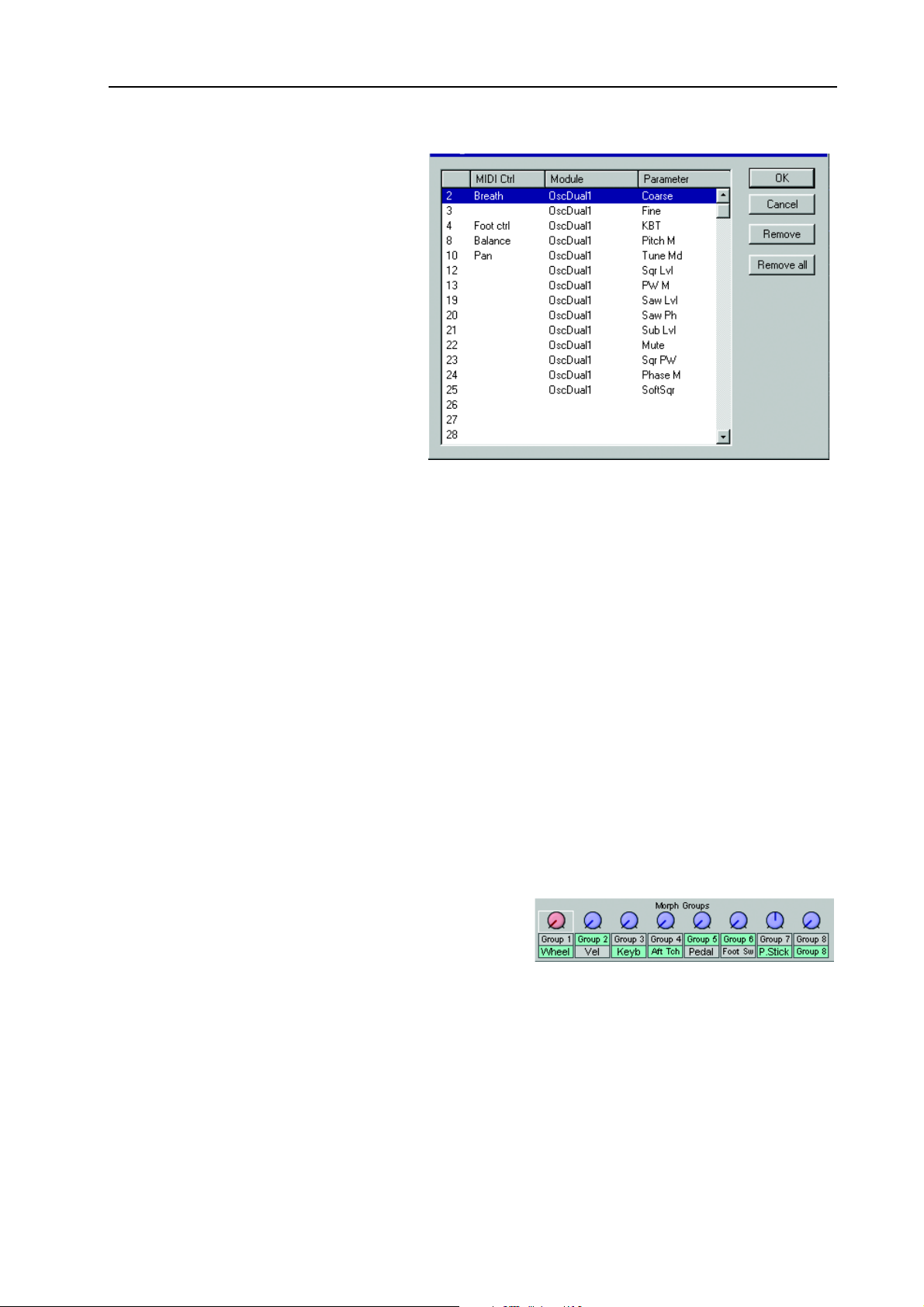
NORD MODULAR G2 V1.1 6. Patches: Morph groups
You may also assign a parameter to an
A
SSIGNABLE KNOB
In that a case, turning a K
sult in editing the parameter, which
subsequently generates MIDI controller
data. Deassign a parameter from a
MIDI controller by highlighting a controller and clicking Remove in the dialog box.
UUUUTTTTOOOO
AAAA
LLLLEEEERRRRSSSS
AAAASSSSSSSSIIIIGGGGNNNN
It’s also possible to automatically assign
MIDI controllers to all parameters of
selected modules. Select the modules
you want to assign MIDI controllers to,
select Tools|Auto Assign MIDI Controllers. Now, all parameters of the selected modules will be automatically assigned to MIDI controller numbers. If you want to deassign MIDI Controllers of specific
modules, select the modules and choose Tools|Deassign MIDI Controllers.
as described earlier.
NOB
will re-
IDI
IDI IDI
CCCCOOOONNNNTTTTRRRROOOOLLLL
M
MIDI
M M
----
SSSSIIIINNNNGGGG
UUUU
TTTTHHHHEEEE
If you want to use one or several A
external devices, you will need to take a detour and assign the A
SSSSSSSSIIIIGGGGNNNNAAAABBBBLLLLEEEE
A
A
A A
NNNNOOOOBBBBSSSS
K
K
K K
SSIGNABLE KNOBS
TTTTOOOO
SSSSEEEENNNNDDDD
MIDI
MIDI
MIDI MIDI
CCCCOOOONNNNTTTTRRRROOOOLLLLLLLLEEEERRRRSSSS
to exclusively transmit MIDI controller data to
SSIGNABLE KNOBS
to parameters on modules that are not used (connected) in the Patch. Then, assign the parameters to MIDI controllers. Very
useful for this purpose is the MIDI Ctrl send module (see page 195), which does not use any Sound engine resources. You determine which MIDI channel to use directly in this module. Read more about the
MIDI modules in “MIDI group” on page 195.
MMMM
OOOORRRRPPPPHHHH
GGGGRRRROOOOUUUUPPPPSSSS
The Morph function lets you continuously control defined ranges of several parameters in a Patch, using
only a single control source. This lets you produce radical changes in a sound in a very fast and easy way.
Nord Modular G2 features eight separate Morph groups per Patch. A parameter can also be assigned to
several Morph groups - all Morph groups, actually - and thus be controlled differently from several sources. Also, if you use several Variations in a Patch, the Morph group assignments can be totally different for
each Variation.
The Morph groups and their corresponding knobs are
located in the Editor toolbar. There are eight Morph
groups available in each Patch and you may assign a total
of 25 Patch parameters to these Morph groups.
Page 51
Page 56
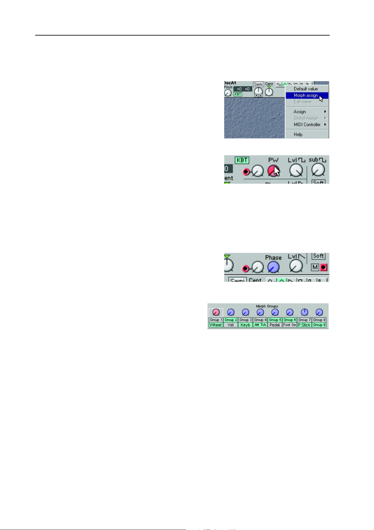
6. Patches: Morph groups NORD MODULAR G2 V1.1
AAAA
SSSSSSSSIIIIGGGGNNNN
1. Click on any of the Morph group knobs in the toolbar to
2. Every parameter assigned to a Morph group should also be
3. Turning the Morph group knob in the toolbar will now control the morphed parameter within the
PPPPAAAARRRRAAAAMMMMEEEETTTTEEEERRRRSSSS
select it. The white frame moves to the selected Morph
group and the Morph group knob turns red. Then Ctrlclick on the knob, button or slider you wish to assign to
the selected Morph group. Alternatively, right-click on the
module parameter and select ‘Morph assign’. The color of
the selected parameter will now change to red to indicate
it’s been assigned to the selected Morph group.
given a Morph range. Place the cursor on the knob that
you assigned to the Morph group. Hold down the Ctrl key
and Click-drag the cursor as if you were turning the knob.
A red sector will appear, indicating the Morph range. The
range will also appear in a yellow hintbox next to the parameter. The initial Morph value is where
the black line is on the knob. Note that if you assign buttons to a Morph group, the Morph range
will always be fixed at the maximum range.
selected range. Note that the morphed knob(s) in the module(s) won’t change visually.
TTTTOOOO
M
AAAA
M
M M
OOOORRRRPPPPHHHH
GGGGRRRROOOOUUUUPPPP
4. If you want to assign parameters to another Morph group,
click another Morph group knob in the Toolbar and
repeat the procedure from step 1. Any parameters assigned
to other Morph groups will now turn blue to indicate they
are morphed from another source.
You can assign each Morph group knob to any of the
predefined controls M
Keyboard Note Values, Aftertouch, Control Pedal, Foot
Switch, P
front panel. If you want to assign a Morph group only to an A
control source, simply click the Group button below the Morph group knob in the Toolbar. Then, rightclick the Morph group knob and select Assign|Page X|Knob. The Group buttons can also be renamed by
right-clicking and selecting ‘Edit name’. You can also assign the Morph group knob to a MIDI controller
by right-clicking and selecting MIDI Controller|Assign.
DDDD
EEEEAAAASSSSSSSSIIIIGGGGNNNN
To deassign a parameter from a Morph group, right-click on the parameter and deselect ‘Morph assign’
in the popup.
To deassign all assigned parameters from a Morph group, right-click on the Morph group knob in the
Toolbar and select ‘Clear’.
ITCH STICK
PPPPAAAARRRRAAAAMMMMEEEETTTTEEEERRRRSSSS
OD WHEEL
, or to A
SSIGNABLE KNOBS
, Keyboard Velocity,
on the
FFFFRRRROOOOMMMM
M
M
AAAA
OOOORRRRPPPPHHHH
M M
SSIGNABLE KNOB
GGGGRRRROOOOUUUUPPPP
instead of the predefined
Page 52
Page 57

NORD MODULAR G2 V1.1 6. Patches: Morph groups
EEEE
CCCC
MMMM
DDDDIIIITTTT
PPPPAAAARRRRAAAAMMMMEEEETTTTEEEERRRRSSSS
The Morph range will always start at the current position of a knob or slider. The relationship between
the setting of the parameter and the Morph range will be fixed, even if you move the setting of the parameter after a Morph range has been set.
You can edit the morph range (the size of the sector) by using the mouse in conjunction with the Ctrl
key on the computer keyboard. You can also use the computer keyboard Up and Down Arrow keys in
conjunction with the Ctrl key to increase and decrease the focused parameter’s Morph range.
You can also get a read-out of which Morph group a parameter is assigned to by pressing the F7 function
key on the computer keyboard. Pressing the F5 key displays the Morph ranges (start and end values) of
the assigned (morphed) parameters.
M
OOOOPPPPYYYY
M
AAAA
OOOORRRRPPPPHHHH
M M
GGGGRRRROOOOUUUUPPPPSSSS
OOOORRRRPPPPHHHH
M
M
M M
GGGGRRRROOOOUUUUPPPPSSSS
OOOOPPPPYYYY
Right-click the Morph group knob in the Toolbar you wish to copy. Select Copy To|Group X. You may
also want to delete the original Morph group source afterwards by right-clicking the Morph group knob
and selecting ‘Clear’.
OOOORRRRPPPPHHHH
Each Variation in a Patch can have its own unique Morph group assignments.
CCCC
Any Morph group assignments are automatically copied when you copy the entire Variation as described
in “Copy a Variation” on page 47.
IIIINNNN
GGGGRRRROOOOUUUUPPPP
IIIINNNN
SSSSEEEEPPPPAAAARRRRAAAATTTTEEEE
M
M
AAAA
OOOORRRRPPPPHHHH
M M
TTTTOOOO
BBBBEEEETTTTWWWWEEEEEEEENNNN
GGGGRRRROOOOUUUUPPPP
AAAANNNNOOOOTTTTHHHHEEEERRRR
V
V
AAAARRRRIIIIAAAATTTTIIIIOOOONNNNSSSS
V V
AAAARRRRIIIIAAAATTTTIIIIOOOONNNNSSSS
V
V
V V
SSSSOOOOUUUURRRRCCCCEEEE
A
A
WWWWOOOORRRRDDDD
A A
Keyboard Morph lets you control the Morphed parameters differently depending on where on the keyboard you play. The minimum source value is the lowest key of the Nord Modular G2 keyboard when
no Octave Shift is used, i.e. note C2, and maximum is the highest key, i.e C5. When you transpose the
keyboard up or down, the Keyboard Morph range will extend beyond the set Morph limits.
Tip! This function makes it easy to create, for example, ”custom made” Filter Keyboard Tracking. Just
make sure you deselect the KBT function in the filter module to make this work as intended.
MMMM
OOOORRRRPPPPHHHHIIIINNNNGGGG
It’s not possible to Morph a clock-synched parameter. You can assign and set a Morph range on a clocksynched parameter, but Morphing it will have no effect.
AAAABBBBOOOOUUUUTTTT
CCCCLLLLOOOOCCCCKKKK
K
K
EEEEYYYYBBBBOOOOAAAARRRRDDDD
K K
----
SSSSYYYYNNNNCCCCHHHHEEEEDDDD
M
M
OOOORRRRPPPPHHHH
M M
MMMMOOOODDDDUUUULLLLEEEE
PPPPAAAARRRRAAAAMMMMEEEETTTTEEEERRRRSSSS
Page 53
Page 58

7. Performances: What is a Performance? NORD MODULAR G2 V1.1
7. P
7. PE
7. P7. P
ER
RFFFFO
EE
RR
ORRRRM
OO
MAAAAN
MM
NCCCCEEEESSSS
NN
WWWW
HHHHAAAATTTT
SSSS
UUUU
PPPPLLLLOOOOAAAADDDDIIIINNNNGGGG
P
IIIISSSS
A Performance is a complete setup (combination) of up to four Patches - one in each Slot. The Nord
Modular G2 has 1024 (8 x 128) memory locations for Performances. A Performance contains information about which Slots should be active, layered and also any Keyboard Split settings and Master Clock
settings. A Performance also contains information about a number of other settings. Later in this chapter
follows a detailed list of what settings are saved in a Performance.
PPPPEEEECCCCIIIIAAAALLLL
A Performance in the Nord Modular G2 system doesn’t necessarily have to be just four layered/split
Patches in combination. Thanks to the internal audio Bus functionality in the G2 system, it’s possible to
have, for example, the audio output signals of three Patches in three Slots routed to a “global” Effects
Patch in the fourth Slot.
When you upload a Performance from the synth to the Editor, you replace the four Patches currently in
the Slots A to D with the Patches in the Performance. You also recall other settings as listed in the table
later in this chapter.
1. Click the Prf button in the Toolbar.
2. Open the File Browser by selecting Tools|File Browser from the menu. The Browser window opens
up. Click on the Synth tab to display the Performances of the internal memory in the synth.
P
AAAA
FFFFEEEEAAAATTTTUUUURRRREEEESSSS
EEEERRRRFFFFOOOORRRRMMMMAAAANNNNCCCCEEEE
P P
P
P
AAAA
P P
P
P
IIIINNNN
EEEERRRRFFFFOOOORRRRMMMMAAAANNNNCCCCEEEESSSS
P P
EEEERRRRFFFFOOOORRRRMMMMAAAANNNNCCCCEEEE
????
TTTTOOOO
TTTTHHHHEEEE
E
E
DDDDIIIITTTTOOOORRRR
E E
3. Double-click on a Performance icon in the File Browser to load the Performace in the synth and
upload to the Editor. The focused Patch in the Performance is placed on top in the Editor.
CCCC
RRRREEEEAAAATTTTIIIINNNNGGGG
SSSS
EEEELLLLEEEECCCCTTTTIIIINNNNGGGG
1. Select File|New Performance
2. Select Patches for the Slots by using the File|Open To|Slot X command. Repeat the procedure for
the Slots you want to use.
3. To activate or exclude a Slot from the Performance, Shift-click on the desired Slot button in the
Toolbar. To enable or disable Keyboard Assign (which Slots are going to be controlled from the keyboard), Ctrl-click on the desired Slot button(s). Note that even if you exclude a Slot from the Per-
formance, any Patches in deselected Slots will still be saved with the Performance. If you want to
keep the file size of a Performance down, load any deselected Slots with empty Patches (no modules in the Patch window).
Page 54
P
P
AAAA
P P
P
P
AAAATTTTCCCCHHHHEEEESSSS
P P
EEEERRRRFFFFOOOORRRRMMMMAAAANNNNCCCCEEEE
FFFFOOOORRRR
TTTTHHHHEEEE
S
S
S S
IIIINNNN
LLLLOOOOTTTTSSSS
TTTTHHHHEEEE
E
E
DDDDIIIITTTTOOOORRRR
E E
Page 59

NORD MODULAR G2 V1.1 7. Performances: Storing a Performance
EEEE
DDDDIIIITTTTIIIINNNNGGGG
This is done just as in Patch (non-Performance) mode. To activate a Slot for editing, simply click the
desired Slot button in the Toolbar. The focused Slot is indicated by a white frame surrounding the Slot
button. Note that to be able to play the selected Slot, you also need to activate Keyboard Assign for it.
Do this by Ctrl-clicking the selected Slot button (a red horizontal bar appears above the Slot button).
KKKK
EEEEYYYYBBBBOOOOAAAARRRRDDDD
The Keyboard Split function allows you to define separate keyboard ranges for all Slots in the
Performance. It’s also possible to have the Slots’
keyboard ranges overlapping each other. Activate Keyboard Split as follows:
1. Select Performance|Performance Settings
from the menu.
2. Check in the Keyboard Range box. The red
LED above the KB S
synth front panel lights up to indicate that
the keyboard is enabled for split.
3. Type in the keyboard ranges (MIDI Note ranges) for each of the Slots in the Lower and Upper
boxes.
CCCC
OOOOMMMMBBBBIIIINNNNIIIINNNNGGGG
Layering Slots simply means that you overlap keyboard ranges for the Slots you want to layer.
TTTT
G
G
HHHHEEEE
G G
Each Patch in a Performance can have its own parameter assignments, just
like in Patch (non-Performance) mode. In addition to
this, a Performance can have
a separate setup of 5x3 Programmable Parameter Pages
with up to 8 parameters per page - the Global Parameter Pages. To assign parameters to the Global Parameter Pages, click the Global Pages button in the Tools|Parameter Pages window and assign the parameters as described in “Assign a parameter to a knob” on page 48. When you assign parameters to the
Global Parameter Pages each assignment will be displayed with an initial letter indicating from which Slot
the module parameter originates from.
S
S
S S
S
S
S S
LLLLOOOOBBBBAAAALLLL
(K
(K
PPPPLLLLIIIITTTT
(K (K
PLIT
PPPPLLLLIIIITTTT
P
P
P P
AAAANNNNDDDD
AAAARRRRAAAAMMMMEEEETTTTEEEERRRR
EEEEYYYYBBBBOOOOAAAARRRRDDDD
button on the
L
L
AAAAYYYYEEEERRRR
L L
P
P
AAAAGGGGEEEESSSS
P P
R
R
R R
AAAANNNNGGGGEEEE
))))
SSSS
TTTTOOOORRRRIIIINNNNGGGG
Note! When the Nord Modular G2 is shipped from factory, Memory Protect is set to ‘On’. To be able
to store Performances, first disable the Memory Protect function. Select Synth|Synth Settings and uncheck the Memory Protect On box.
P
P
AAAA
EEEERRRRFFFFOOOORRRRMMMMAAAANNNNCCCCEEEE
P P
Page 55
Page 60

7. Performances: Extracting Patches from a Performance NORD MODULAR G2 V1.1
SSSS
TTTTOOOORRRRIIIINNNNGGGG
Storing a Performance in the synth from the Editor can be done in two ways. Either, select Synth|Save
in Synth from the menu. Then, select memory location and click OK, or:
1. Select Tools|File Browser to open the Browser window.
2. Click on the Perf tab to display the Performances in the internal memory of the synth.
3. Right-click on a Bank icon, select ‘Save Current Performance to’ and select a memory location for
your Performance.
SSSS
AAAAVVVVIIIINNNNGGGG
Select File|Save or Save As... from the menu. If you selected ‘Save As...’, select a folder and press/click OK.
RRRR
EEEENNNNAAAAMMMMIIIINNNNGGGG
It’s also possible to name each of the Patches in a Performance individually. In Performance Mode, simply click on a Slot to focus the Patch. Enter a new Patch name in the Patch display box. Click on another
Slot button to put the next Patch in focus. Enter a new Patch name in the Patch display box. When you’re
done, store and/or save the Performance as described above.
EEEE
XXXXTTTTRRRRAAAACCCCTTTTIIIINNNNGGGG
OOOONNNN
IIIINNNN
TTTTHHHHEEEE
TTTTHHHHEEEE
SSSSIIIINNNNGGGGLLLLEEEE
P
P
P P
SSSSYYYYNNNNTTTTHHHH
CCCCOOOOMMMMPPPPUUUUTTTTEEEERRRR
P
P
AAAATTTTCCCCHHHHEEEESSSS
P P
AAAATTTTCCCCHHHHEEEESSSS
IIIINNNN
FFFFRRRROOOOMMMM
P
P
EEEERRRRFFFFOOOORRRRMMMMAAAANNNNCCCCEEEESSSS
P P
P
P
AAAA
EEEERRRRFFFFOOOORRRRMMMMAAAANNNNCCCCEEEE
P P
The Patches used in the Slots of a Performance are not references to Patches in the Patch memory of the
synth, but complete Patches “on their own” in the Performance. You will find several unique Patches in
the factory Performances; Patches that you will not find in any of the internal Patch memory locations.
You may want to extract such a Patch, to use as a single regular Patch, or to make it part of another Performance.
EEEE
XXXXTTTTRRRRAAAACCCCTTTT
Click on the Slot button that contains the Patch you want to extract. Click the Prf button in the Toolbar
to exit Performance mode. Then, select Synth|Save In Synth. Select Patch memory location and click
OK.
EEEE
XXXXTTTTRRRRAAAACCCCTTTT
Select File|Save From|Slot X. Select folder, rename the Patch if you like, and click OK.
DDDD
EEEELLLLEEEETTTTIIIINNNNGGGG
Do like this to delete a Performance from the internal memory of the synth:
1. Select Tools|File Browser to open the File Browser window.
2. Click on the Perf tab to display the Performances in the internal memory of the synth.
P
P
AAAA
AAAATTTTCCCCHHHH
P P
P
P
AAAA
AAAATTTTCCCCHHHH
P P
P
P
EEEERRRRFFFFOOOORRRRMMMMAAAANNNNCCCCEEEESSSS
P P
AAAANNNNDDDD
AAAANNNNDDDD
SSSSTTTTOOOORRRREEEE
SSSSAAAAVVVVEEEE
OOOONNNN
IIIINNNN
IIIINNNN
IIIITTTT
IIIITTTT
TTTTHHHHEEEE
TTTTHHHHEEEE
TTTTHHHHEEEE
SSSSYYYYNNNNTTTTHHHH
CCCCOOOOMMMMPPPPUUUUTTTTEEEERRRR
SSSSYYYYNNNNTTTTHHHH
3. If necessary, double-click a Bank icon. then right-click on a Performance icon and select Delete.
Page 56
Page 61

NORD MODULAR G2 V1.1 7. Performances: Exiting Performance Mode
EEEE
XXXXIIIITTTTIIIINNNNGGGG
To exit Performance mode, click the Prf button in the Toolbar. Now you return to the regular Patch
mode. Note that the four Slots contain the same Patches they had in Performance mode and also that any
Layering and Keyboard Range settings remain unchanged.
P
P
EEEERRRRFFFFOOOORRRRMMMMAAAANNNNCCCCEEEE
P P
M
M
M M
OOOODDDDEEEE
Page 57
Page 62
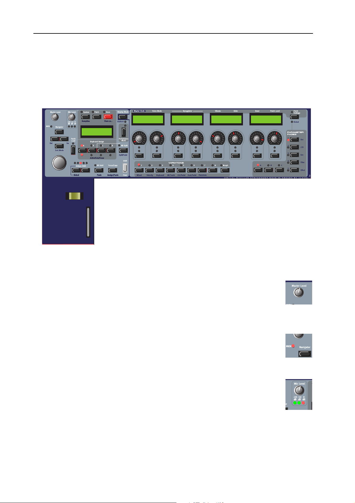
8. Working with the synth: Panel controls NORD MODULAR G2 V1.1
8. W
8. WO
8. W8. W
OR
RKKKKIIIIN
OO
RR
NG
G
NN
GG
W
WIIIITTTTH
WW
H
T
HH
TH
HE
TT
HH
E
S
EE
SYYYYN
SS
NTTTTH
NN
H
HH
PPPP
AAAANNNNEEEELLLL
LLLL
EEEEFFFFTTTT
CCCCOOOONNNNTTTTRRRROOOOLLLLSSSS
Patch 1:1
Chops Bass TB
PPPPAAAANNNNEEEELLLL
SSSSEEEECCCCTTTTIIIIOOOONNNN
ADSR-Env1
Attack Decay
ADSR-Env1
Sustain Re lease
Filter-Env1
Attack Decay
Filter-Env1
Sustain Release
AAAASSSSTTTTEEEERRRR
MMMM
The M
PHONES
used to control the entire instrument’s output level. To affect the volume of a Patch from
MIDI, you have to assign MIDI Controller #7 to any of the Patch Gain knobs in the respective Patch (see more about this on “Patch Level” on page 99).
MIDI LED
MIDI LED
MIDI LEDMIDI LED
The MIDI LED indicates incoming MIDI Note, Controller and SysEx messages on any
MIDI channel. MIDI messages on any of the Slot’s MIDI Channels and the Global MIDI
Channel are indicated by long LED blinks. Messages on other MIDI Channels are indicated
by short LED blinks.
MMMM
IIIICCCC
L
L
L L
The M
three LED
NPUT
I
of the line level signal routed to the I
affects the XLR I
EEEEVVVVEEEELLLL
L
L
L L
ASTER LEVEL
output. The M
EEEEVVVVEEEELLLL
IC LEVEL
S
which show the input level of the dynamic microphone connected to the XLR
on the rear panel. If you don’t use a mic, the L
knob controls the output level of all four OUT jacks and the H
ASTER LEVEL
knob controls the XLR mic preamp level. Below the M
NPUT
- not the I
knob does not send or receive any MIDI CC# but is
IC LEVEL
LED
EVEL
1 input instead. Note that the MIC L
N
1 input.
N
S
will indicate the input level
EVEL
-
EAD
knob are
knob only
Page 58
Page 63

NORD MODULAR G2 V1.1 8. Working with the synth: Panel controls
YYYYSSSSTTTTEEEEMMMM
SSSS
Above the M
AAAATTTTCCCCHHHH
, P
, P
, P, P
AIN DISPLAY
AAAANNNNDDDD
TTTTOOOORRRREEEE
S
S
S S
are the S
BBBBUUUUTTTTTTTTOOOONNNNSSSS
YSTEM
(see page 79) and P
ATCH
(see page 62)
buttons which can be used to enter all system and Patch related menus. The
S
TORE
button (see page 67 and page 77) is used for storing Patches and Perform-
ances.
AAAAVVVVIIIIGGGGAAAATTTTOOOORRRR
NNNN
Below the M
tons, the N
igate in the M
functions. Below the N
TARY DIAL
BBBBUUUUTTTTTTTTOOOONNNNSSSS
ASTER LEVEL
AVIGATOR
AIN DISPLAY
buttons. These are used to nav-
. With the R
, R
, R
, R, R
OOOOTTTTAAAARRRRYYYY
D
D
D D
IIIIAAAALLLL
knob is a set of four but-
and to select different
AVIGATOR
OTARY DIAL
buttons is the R
you can select
AAAANNNNDDDD
O
M
M
M M
-
AAAAIIIINNNN
IIIISSSSPPPPLLLLAAAAYYYY
D
D
D D
1:2 Audio In
Dream synth
Patches and Performances, enter various kind of System data etc.
AAAATTTTCCCCHHHH
PPPP
L
L
L L
OOOOAAAADDDD
Press this button when you want to load a selected Patch or Performance into the focused
Slot/Slots (see page 61 and page 75).
LLLLOOOOTTTT
BBBBUUUUTTTTTTTTOOOONNNNSSSS
SSSS
Below the M
AIN DISPLAY
are the four S
LOT
buttons (A, B, C and D). You can
load one Patch in each of the Slots at a time. See “Load a Patch from memory”
on page 61, “Activate several Slots” on page 70 and “Creating a Performance”
on page 75 for info on how to use the Slots.
CCCCTTTTAAAAVVVVEEEE
OOOO
Lets you transpose the keyboard +/-2 octaves. In default mode, the O
tons controls each of the Slots separately. In Global Octave Shift mode (S
TAVE SHIFT
notes on the MIDI O
KB H
KB H
KB HKB H
Press the KB H
HHHHIIIIFFFFTTTT
S
S
S S
BBBBUUUUTTTTTTTTOOOONNNNSSSS
CTAVE SHIFT
HIFT
buttons) the octave shift controls all Slots and also affects the output MIDI
UT
jack of the synth.
OOOOLLLLDDDD
/P
/P
/P/P
AAAANNNNIIIICCCC
OLD
button to make every note or chord you play sustain until you press
but-
+left O
C
any new keys. The Keyboard Hold function is also very useful together with the Arpeggiator (see “Arpeggiator” on page 63). If notes should hang or the synth should behave
strange, press S
HHHHEEEE
OOOOCCCCUUUUSSSS
F
F
TTTT
F F
HIFT
/C
/C
/C/C
+KB H
OOOOPPPPYYYY
To the right below the M
OLD
SSSSSSSSIIIIGGGGNNNN
/(A
/(A
/(A/(A
AIN DISPLAY
to send an internal All Notes Off to the synth.
/P
/P
/P/P
AAAASSSSTTTTEEEE
BBBBUUUUTTTTTTTTOOOONNNN
)
)
) )
section you find the F
OCUS/COPY
button. This
button can be used in many situations, for example when you want to copy & paste various things and also when you assign parameters to Parameter Pages. Holding S
CUS/COPY
alternates the functionality to Assign/Paste.
HIFT+FO
-
-
Page 59
Page 64

8. Working with the synth: Panel controls NORD MODULAR G2 V1.1
-
EEEERRRRFFFFOOOORRRRMMMMAAAANNNNCCCCEEEE
PPPP
Below the M
S
TICK
and M
“Bend” on page 64) as well as an entire Morph group. The M
CCCCOOOONNNNTTTTRRRROOOOLLLLSSSS
AIN DISPLAY
OD WHEEL
section you find the performance controls: the P
. The P
ITCH STICK
can be used to control pitch bend (see
OD WHEEL
ITCH
can control
Vibrato (see page 63) and also a separate Morph group. See “Morph groups” on
page 71 for info on how to use these controls with Morph groups.
IIIISSSSPPPPLLLLAAAAYYYY
DDDD
Lets you switch between two different display modes for the A
SIGNABLE DISPLAYS
module names and parameter names. When you turn an A
ABLE KNOB
name is temporarily replaced by the parameter value. In the other
display mode, the parameter names and values are constantly displayed. However, the module names are not shown in this mode.
Hold S
names of button parameters instead of knob parameters in the A
SIGNABLE DISPLAYS
bined knob+button parameters to the A
Pressing only the D
OOOODDDDEEEE
M
M
M M
or press an A
HIFT
and press the D
UUUUTTTTTTTTOOOONNNNSSSS
/B
/B
/B/B
. By default, the A
SSIGNABLE BUTTON
ISPLAY MODE
SSIGNABLE DISPLAYS
, the parameter
button to display the
show
SSIGN
. This is useful when you have assigned com-
SSIGNABLE DISPLAYS
ISPLAY MODE
button in ‘Button’ mode will
-
S
-
FltNord1--------|
Freq Res
-
S
.
Freq Res
622.5Hz 1.72
change the parameter display as described above.
EEEERRRRFFFFOOOORRRRMMMMAAAANNNNCCCCEEEE
PPPP
M
M
M M
OOOODDDDEEEE
In Performance mode you can create split/layers configurations of up to 4 Slots. See “Per-
formances” on page 74.
KB S
KB S
KB SKB S
PPPPLLLLIIIITTTT
M
M
M M
OOOODDDDEEEE
/S
/S
/S/S
EEEETTTT
S
S
S S
PPPPLLLLIIIITTTT
P
P
P P
OOOOIIIINNNNTTTT
Lets you split the keyboard and play/control different Slots from different keyboard
zones. See “Keyboard Split” on page 76.
HHHHEEEE
TTTT
The S
S
S
S S
HIFT
HHHHIIIIFFFFTTTT
LLLLEEEEAAAARRRR
/C
/C
/C/C
BBBBUUUUTTTTTTTTOOOONNNN
button is used to activate functions printed below some buttons on the front
panel. It’s also used for deleting entire Morph groups and for clearing Variations.
RRRR
IIIIGGGGHHHHTTTT
PPPPAAAANNNNEEEELLLL
SSSSSSSSIIIIGGGGNNNNAAAABBBBLLLLEEEE
AAAA
SSSSEEEECCCCTTTTIIIIOOOONNNN
NNNNOOOOBBBBSSSS
K
K
K K
AAAANNNNDDDD
UUUUTTTTTTTTOOOONNNNSSSS
B
B
B B
WWWWIIIITTTTHHHH
IIIISSSSPPPPLLLLAAAAYYYYSSSS
D
D
D D
Module parameters in a Patch can freely be assigned to any
of the 8 A
A
SSIGNABLE DISPLAYS
SSIGNABLE KNOBS
UTTONS
or B
. Around each A
below the four
SSIGNABLE KNOB
EnvADSR1----- ---Attack Decay
------------- ---|
Sustain R elease
you’ll also find circular LED graphs which give you instant
visual feedback of the coarse value of the assigned parameter. As soon as a module parameter has been assigned to an
A
SSIGNABLE KNOB
exact value (when you turn the K
or B
UTTON
, the parameter name and
NOB
) is shown above in
EnvFilter1--- -Attack Decay
Page 60
Page 65

NORD MODULAR G2 V1.1 8. Working with the synth: Load a Patch from memory
the corresponding A
SSIGNABLE DISPLAY
. You can assign a maximum of 15 Columns (see below), each
containing up to 8 parameters (120 parameters in total) per Patch.
AAAARRRRIIIIAAAATTTTIIIIOOOONNNN
VVVV
There are 8 V
OOOORRRRPPPPHHHH
/M
/M
/M/M
ARIATION
BBBBUUUUTTTTTTTTOOOONNNNSSSS
buttons with which you can
Attack Decay Sustain Release Attack Decay
select up to eight different Patch Variations (complete
parameter setups) within each Patch (see “Patch pa-
rameter Variations” on page 65). In ‘Morph Mode’,
these 8 buttons function as Morph group selection
buttons. They are used when you want to control several parameters in a Patch from a single control source
(see “Morph groups” on page 71).
AAAATTTTCCCCHHHH
PPPP
EEEETTTTTTTTIIIINNNNGGGGSSSS
S
S
S S
/G
/G
/G/G
LLLLOOOOBBBBAAAALLLL
This button is used when you want to switch display between the Patch parameters which are printed above the A
SIGNABLE DISPLAYS
Parameter Pages (see page 64). Press S
TINGS
to enter the Global Parameter Pages (see page 76).
RRRROOOOGGGGRRRRAAAAMMMMMMMMAAAABBBBLLLLEEEE
PPPP
To the right are 5 main P
bination with 3 C
(see page 63) and the Programmable
HIFT+PATCH SET
AAAARRRRAAAAMMMMEEEETTTTEEEERRRR
P
P
P P
OLUMN
ARAMETER PAGE
buttons for a total of 15 Program-
AAAAGGGGEEEESSSS
P
P
P P
buttons in com-
BBBBUUUUTTTTTTTTOOOONNNNSSSS
S
Off Off
-
50 cnt 1.0 s
-
mable Parameter Pages per Patch. Each of these pages can
contain the 8 A
SSIGNABLE KNOBS
or B
UTTONS
mentioned
above. See page 64 and page 76 for info on how to use these
pages.
2 semi -7.3 dB
On MuteOff
KKKK
EEEEYYYYBBBBOOOOAAAARRRRDDDD
S
S
S S
PPPPLLLLIIIITTTT
LED
LED
LED LED
SSSS
Above the keyboard are four Keyboard Split LEDs which
indicate current keyboard split position in Keyboard Split
mode (see “Keyboard Split” on page 76).
LLLL
OOOOAAAADDDD
AAAA
Press a S
P
P
AAAATTTTCCCCHHHH
P P
LOT
button to select the Slot in which to load
FFFFRRRROOOOMMMM
MMMMEEEEMMMMOOOORRRRYYYY
the Patch. Load the Patch into the Slot by first selecting Bank (if necessary) with the U
TOR
buttons and then turning the R
P/DOWN NAVIGA
OTARY DIAL
-
to
select the Patch. Load the selected Patch into the Slot
by pressing the P
ATCH LOAD
button. Note that every
time you load a Patch into a Slot, there will be a brief
moment of silence when the Sound engine recalculates
the Patch data
SSSS
EEEEAAAARRRRCCCCHHHH
FFFFOOOORRRR
AAAANNNNDDDD
LLLLOOOOAAAADDDD
P
P
AAAA
AAAATTTTCCCCHHHH
P P
By default, when you load a Patch into a Slot, by first selecting Bank with the U
buttons and then turning the R
OTARY DIAL
and pressing P
ATCH LOAD
1:2 Synth
Dream synth
P/DOWN NAVIGATOR
, the Patches are displayed by
Page 61
Page 66
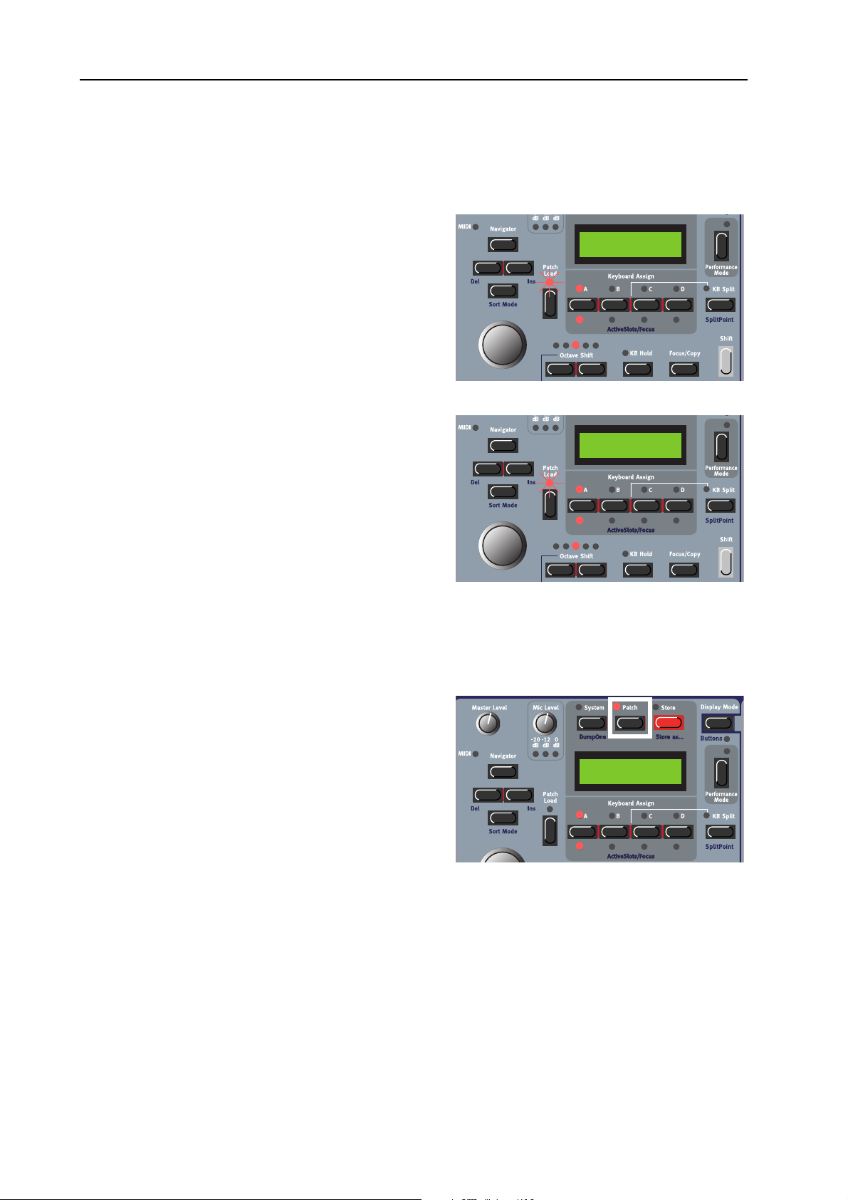
8. Working with the synth: Create a Patch NORD MODULAR G2 V1.1
memory location number. However, you can change the sort/search mode to either ‘Alphanumerical’ or
by ‘Category’.
EEEEAAAARRRRCCCCHHHH
SSSS
By pressing the S
FFFFOOOORRRR
AAAA
HIFT
P
P
P P
AAAATTTTCCCCHHHH
+ D
IIIINNNN
AAAALLLLPPPPHHHHAAAANNNNUUUUMMMMEEEERRRRIIIICCCCAAAALLLL
OWN NAVIGATOR
you will be able to load Patches in alphabetical order
rather than by memory location number. Select letter
by pressing the U
select Patch with the R
EEEEAAAARRRRCCCCHHHH
SSSS
By holding down S
IGATOR
button twice you will be able to load Patches
P/DOWN NAVIGATOR
OTARY DIAL
FFFFOOOORRRR
AAAA
AAAATTTTCCCCHHHH
P
P
P P
HIFT
and pressing the D
.
IIIINNNN
AAAA
SSSSPPPPEEEECCCCIIIIFFFFIIIICCCC
by Category rather than by memory location number.
The Patches within a Category will now be displayed
in alphanumerical order. Select Category by pressing
P/DOWN NAVIGATOR
the U
with the R
CCCC
RRRREEEEAAAATTTTEEEE
OTARY DIAL
P
P
AAAA
P P
AAAATTTTCCCCHHHH
buttons and select Patch
.
buttons
buttons and
AAAATTTTEEEEGGGGOOOORRRRYYYY
C
C
C C
OWN NAV
OOOORRRRDDDDEEEERRRR
-
D 1:2
Dream synth
Synth 1:2
Dream synth
This can only be done in the Editor. Please refer to “Patches (in-depth)” on page 40.
EEEE
DDDDIIIITTTT
AAAA
Press the P
Hold down S
P
P
P P
AAAATTTTCCCCHHHH
ATCH
button above the M
HIFT
and press the D
AIN DISPLAY
OWN NAVIGATOR
.
button to get to the first module in the Voice Area
(VA) of the Patch. The module currently “in focus” in
the Patch will appear in the M
AIN DISPLAY
with its
Morphs
name and visual position in the Editor within brackets
[1:1] (first row, first column) The first module’s (up
to) eight parameters will appear in the A
D
ISPLAYS
rameters by turning the A
ing the A
N
AVIGATOR
. You can now change the values of the pa-
SSIGNABLE KNOBS
SSIGNABLE BUTTONS
. Navigate to the next module by pressing the D
button or turning the R
SSIGNABLE
OTARY DIAL
ters, the remaining parameters can be found by pressing the C
buttons. Hold down the S
HIFT
button and press the U
or press-
. If a module should contain more than eight parame-
OLUMN
P/DOWN NAVIGATOR
2 and C
OLUMN
change Patch Area focus between the Toolbar (Morph groups), Voice Area and the FX Area.
OWN
or R
IGHT
3 Parameter Pages
button to immediately
Page 62
Page 67

NORD MODULAR G2 V1.1 8. Working with the synth: Edit a Patch
Play on the synth and turn
SSIGNABLE KNOBS
the A
to
instantly hear what is happening with the sound. If
PA [1:1]
MultiFilter1
MultiFilter1- ---Freq Freq M
connected, the Editor will
echo any adjustments that
you make from the synth
front panel. When editing
module parameters it can be useful to switch Display Mode (see page 60) to constantly view the actual
values of each parameter in the A
SSIGNABLE DISPLAYS
. Some modules, like Mixers with Mute buttons,
have a combination of button+knob parameters assigned to each individual control. By default, the A
SIGNABLE DISPLAY
S
HIFT
and press the D
shows the knob parameter name. To view the button parameter name instead, hold
ISPLAY MODE
button.
-------------- --Res dB/Oct
------------- ---|
Bypass PWidth
S
-
EEEE
P
P
DDDDIIIITTTT
P P
Press the P
AAAATTTTCCCCHHHH
S
S
EEEETTTTTTTTIIIINNNNGGGGSSSS
S S
1:1 Bass
ATCH SETTINGS
120 BPM 14 (16)
Stop Poly
1/16 Rnd
Off 1 Oct
50 cnt 1.0 s
Off Off
button to the top right of the panel to display the “global” Patch Parameters
for the Patch. The parameter names are printed on the panel above each A
can edit them by turning the A
SSIGNABLE KNOBS
Revert back to Patch Edit mode by pressing the P
AAAASSSSTTTTEEEERRRR
MMMM
C
C
C C
LLLLOOOOCCCCKKKK
and/or the A
button again.
ATCH
SSIGNABLE BUTTONS
2 semi -7.3 dB
On MuteOff
SSIGNABLE DISPLAY
.
and you
Set the Master Clock Rate with the corresponding Knob. Activate/stop the Master Clock with the corresponding Button below the Knob.
OOOOIIIICCCCEEEE
VVVV
M
M
M M
OOOODDDDEEEE
Set requested polyphony with the Knob (2-32 voices). The actual polyphony is displayed together with
the requested polyphony within parenthesis. Select Voice Mode (Poly, Mono or Legato) with the Button
below the Knob. In Legato mode, the Envelope modules don’t retrig when you play in a legato fashion,
i.e. when you play a new key before releasing the previous key.
RRRRPPPPEEEEGGGGGGGGIIIIAAAATTTTOOOORRRR
AAAA
Select Period (sync division) for the Arpeggiator in relation to the Master Clock rate with the Knob. Activate/stop the Arpeggiator with the Button below the Knob. Note that the Master Clock has to be active
for the Arpeggiator to run. Select Direction with the right Knob and Range with the Button below the
Knob. If you want the Arpeggiator to continue when you release the keys, use the KB Hold function described on page 59.
The Arpeggiator uses MIDI Song Position Pointer when synched to an external MIDI Clock, which
means that if you record an arpeggio in an external sequencer, it will always play back the pattern exactly
the same way it was recorded - even if you start the sequencer in the middle of the sequence.
VVVV
IIIIBBBBRRRRAAAATTTTOOOO
This is a separate vibrato which affects all Oscillator modules in the Patch set to Keyboard Tracking. Set
the Vibrato amount, in cents of a semitone, with the Knob and select control source (Aftertouch, Mod
Page 63
Page 68

8. Working with the synth: Assign parameters to panel controls NORD MODULAR G2 V1.1
Wheel or Off) with the Button below the Knob. Set the Vibrato rate in the System menu described on
page 79.
LLLLIIIIDDDDEEEE
GGGG
The Glide function is mainly intended for use in mono or legato Voice Mode (see above). The glide characteristics can be described as “constant rate”. “Constant rate” means that the greater the “distance” between two subsequent notes, the longer the glide time. Turn the Knob to adjust the glide rate and press
the Button to select glide mode. ‘Normal’ means the glide is always active and ‘Auto’ that glide is active
only when you play legato (you press a new key before you release the previous key). Range: 19 mso (mil-
liseconds per octave) to 6.27 so (seconds per octave).
Note: If you use Glide in polyphonic mode, the glide will be unpredictable and perceived as more or
less random. This is because the glide is between voices rather than between keys. The glide will therefore be from the available voices’ latest note values to the new notes rather than from the previously
pressed keys.
BBBB
EEEENNNNDDDD
Set the Pitch bend range, in semitones, with the Knob. The pitch bend will affect all Oscillator modules
in the Patch set to Keyboard Tracking when you bend the P
function with the Button below the Knob.
ITCH STICK
. Switch on/off the pitch bend
AAAATTTTCCCCHHHH
PPPP
Set the total output level of the Patch with the Knob. Mute the output from the Patch by pressing the
Button below the Knob.
AAAA
SSSSSSSSIIIIGGGGNNNN
It’s possible to assign nearly every module parameter in a Patch to a separate A
SIGNABLE BUTTON
1. Press the P
to enter Patch Edit Mode. Hold down S
press the D
first module in the Voice Area of the Patch.
2. Navigate to the module which contains the parameter you want to assign. The module’s name and
first parameters are shown in the A
PLAYS
ters, you can access the remaining parameters by
pressing the C
EEEEVVVVEEEELLLL
L
L
L L
PPPPAAAARRRRAAAAMMMMEEEETTTTEEEERRRRSSSS
on the synth front panel. Do like this:
ATCH
button above the M
OWN NAVIGATOR
. (If a module contains more than 8 parame-
OLUMN
2 and C
TTTTOOOO
PPPPAAAANNNNEEEELLLL
AIN DISPLAY
HIFT
and
button to get to the
SSIGNABLE DIS
OLUMN
3 buttons.)
CCCCOOOONNNNTTTTRRRROOOOLLLLSSSS
-
SSIGNABLE KNOB
Morphs
or A
-
S
Page 64
Page 69

NORD MODULAR G2 V1.1 8. Working with the synth: Patch parameter Variations
B
3. When you have found the module and parameter
you want to assign to an A
A
SSIGNABLE BUTTON
A
button and turn the parameter K
SSIGN
push the parameter B
, hold down the F
UTTON
SSIGNABLE KNOB
OCUS
NOB
if the module
or
(or
/
Filter1
[1:1]
FltMulti1---- ---Freq Freq M
parameter is a button). In this example we choose
the FltMulti1 Freq parameter.
Note! Some modules, like Mixers with On/Off
buttons, have a combination of button+knob
parameters assigned to each individual control.
If you want to assign these types of “combination parameters” to an A
, you have to copy the knob parameter and paste it by turning the A
TON
parameter combination to be assigned properly.
SSIGNABLE KNOB
SSIGNABLE KNOB
-------------- --Res dB/Oct
and BUT-
for the
4. Press the P
ATCH
button or a P
ARAMETER PAGE
button to exit Patch Edit Mode and revert to nor-
mal “play mode”.
5. Press the desired Parameter Page buttons (P
OLUMN
and C
) to get to the desired destination.
AGE
You can choose freely where to assign a parameter
but it could be convenient to use the Parameter
Page groups printed in blue on the front panel.
Here, we choose Page D (Filter), Column 1.
6. Hold down the S
(Paste) and turn the A
B
UTTON
) you want to assign the module parameter to. We choose to
assign the parameter to the first A
around the A
HIFT
SSIGNABLE KNOB
OCUS/COPY
and F
SSIGNABLE KNOB
buttons
(or push the A
SSIGNABLE KNOB
(or the A
SSIGNABLE BUTTON
SSIGNABLE
. The LED
GRAPH
LED)
s Bass TB
Bass
will light up with the pasted module parameter’s current value and the
parameter name will be shown in the corresponding A
PLAY
.
SSIGNABLE DIS
7. If you want to assign more module parameters, press the P
ATCH
-
button and repeat the procedure from step 3 above. If you have assigned several parameters from the
same module to adjacent A
will only be shown for the first parameter. Then, there will be dashes in the A
SSIGNABLE KNOBS/BUTTONS
in a Page or Column, the module name
SSIGNABLE DISPLAYS
to indicate that the following parameters are from the same module.
MultiFilter1
Freq
PPPP
AAAATTTTCCCCHHHH
WWWW
HHHHAAAATTTT
PPPPAAAARRRRAAAAMMMMEEEETTTTEEEERRRR
V
V
IIIISSSS
AAAA
AAAARRRRIIIIAAAATTTTIIIIOOOONNNN
V V
V
V
AAAARRRRIIIIAAAATTTTIIIIOOOONNNNSSSS
V V
????
A Variation is a complete setup of Patch parameters, i.e. basically all module parameters in a specific
Patch. Variations always reside inside every single Patch. A Patch automatically holds eight different Variations. Each of these Variations are simply different parameter settings of one and the same Patch. You
could compare a single Nord Modular G2 Patch with a complete hard-wired synthesizer where you have
a predefined number of hard-wired “modules”. A Variation in a hard-wired synthesizer would then be a
Page 65
Page 70
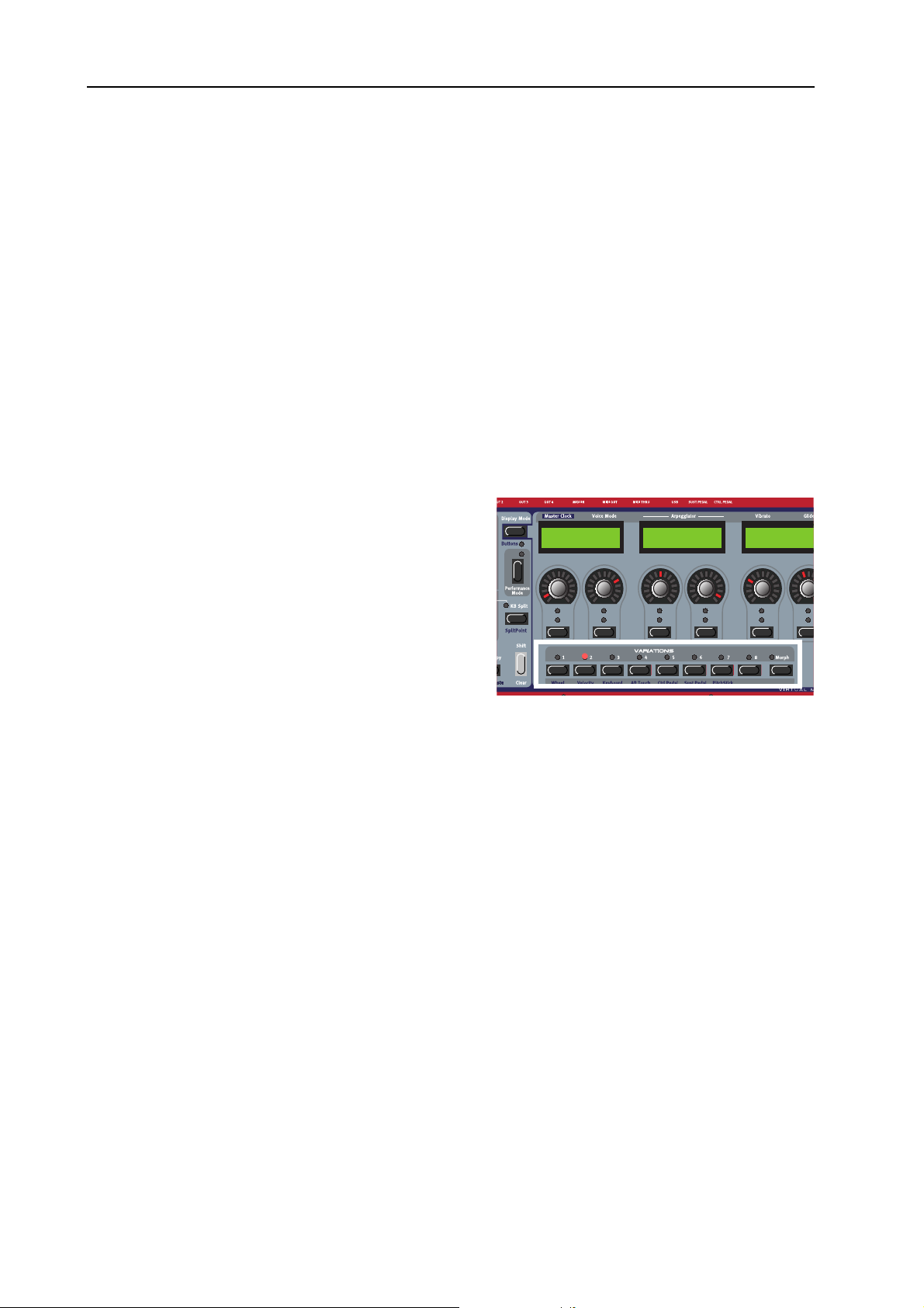
8. Working with the synth: Patch parameter Variations NORD MODULAR G2 V1.1
complete setup of parameters - usually called a “Program”. A Variation in the Nord Modular G2 is exactly
the same but is based on a Patch instead.
PPPP
AAAARRRRAAAAMMMMEEEETTTTEEEERRRRSSSS
There are some things in the Patch that can’t be changed for different Variations: the number of modules,
cable connections and functions in drop-down selectors, such as the waveform selectors of Oscillator C
and D, for example. This is because when the above mentioned things are changed, the Sound engine has
to recalculate the whole Patch and thus cause a brief moment of silence. Since Variation changes should
be “glitch free”, these restrictions are necessary. If you want to be able to switch Oscillator waveforms
between Variations, use modules with radio buttons instead, Oscillator A, B and ShpA, for example. The
same goes for some of the LFO modules.
CCCC
RRRREEEEAAAATTTTEEEE
1. Load a Patch in a Slot. The V
2. Create a new Variation by pressing the V
3. Change the settings on a couple of parameters in
(
(
( (
2 button. The V
indicate it’s now the focused Variation.
the Patch either by using the P
buttons and turning the A
entering Patch Edit mode by pressing the P
button and navigating to the parameters. Note
that modules that have a drop-down selector, for
example Oscillator C and LFO B, can only have a
single waveform for all eight Variations as described above.
TTTTHHHHAAAATTTT
CCCCHHHHAAAANNNNGGGGEEEE
ARIATION
)
)
) )
AAAA
’’’’
CCCCAAAANNNN
V
V
V V
2 LED lights up to
SSIGNABLE KNOBS
TTTT
AAAARRRRIIIIAAAATTTTIIIIOOOONNNN
ARIATION
ARAMETER PAGES
BBBBEEEE
CCCCHHHHAAAANNNNGGGGEEEEDDDD
1 LED lights up.
ARIATION
or by
ATCH
BBBBEEEETTTTWWWWEEEEEEEENNNN
ADSR-Env1
Attack Decay Sustain Release
V
V
AAAARRRRIIIIAAAATTTTIIIIOOOONNNNSSSS
V V
Filter-Env1
Attack Decay
4. Now, press the V
now revert to their original settings.
If you want to have more Variations in your Patch, simply press another V
parameter settings. Each Patch contains eight different Variations. When you store your Patch, all Variations will automatically be saved together with the Patch.
SSSS
CCCC
V
AAAAVVVVEEEE
All active Variations are automatically saved when you store the Patch (see “Store a Patch” on page 67).
OOOOPPPPYYYY
To copy the parameter settings of an existing Variation to another in the Patch, hold down the F
C
S
HIFT+FOCUS/COPY
V
AAAA
AAAARRRRIIIIAAAATTTTIIIIOOOONNNN
V V
V
V
AAAA
AAAARRRRIIIIAAAATTTTIIIIOOOONNNN
V V
OPY
button and press the V
ARIATION
(Paste) and press the destination V
1 button again to put Variation 1 in focus. The parameters you changed
ARIATION
ARIATION
button that you want to copy parameters from. Then hold down
ARIATION
button to paste all parameter values.
button and change
Page 66
OCUS
/
Page 71

NORD MODULAR G2 V1.1 8. Working with the synth: Store a Patch
VVVV
AAAARRRRIIIIAAAATTTTIIIIOOOONNNN
Here you can have a “default” parameter setup for your
Patch. This Init parameter setup can be recalled in any
Variation by pressing the V
HIFT+MORPH
(S
When you do this, the Var Init parameter settings will
be copied to the currently focused Variation.
AAAAVVVVEEEE
SSSS
This has to be done in the Editor. Refer to “Variation Init” on page 47.
CCCC
LLLLEEEEAAAARRRR
You clear a Variation and reset all module parameters in the Patch to their default settings by pressing
S
HIFT
and desired V
SSSS
TTTTOOOORRRREEEE
Storing a Patch will permanently overwrite an existing Patch. Be careful so that you don’t accidentally
erase Patches you want to keep! Note! When the Nord Modular G2 is shipped from factory, Memory
Protect is set to ‘On’. To be able to store Patches, first disable the Memory Protect function. See
“Memory Prot” on page 81.
AAAA
V
V
V V
V
V
AAAA
V V
AAAA
I
I
NNNNIIIITTTT
I I
AR INIT
) to the right of the Variation buttons.
AAAARRRRIIIIAAAATTTTIIIIOOOONNNN
AAAARRRRIIIIAAAATTTTIIIIOOOONNNN
P
P
AAAATTTTCCCCHHHH
P P
NNNNIIIITTTT
I
I
I I
ARIATION
button
button.
Storing a Patch on the Nord Modular G2 can be done in two ways:
SSSS
TTTTOOOORRRRIIIINNNNGGGG
1. Press the S
starts flashing.
2. Select memory location by turning the R
D
D
through the memory locations, you can see the
Patch names in the D
from overwriting a Patch that you want to keep.
3. Press S
SSSS
TTTTOOOORRRRIIIINNNNGGGG
To make it easier to find different types of sounds in the synth’s memory it’s possible to define a category
for each Patch. When you’re looking for a specific type of sound you can then search by Category, instead
of Alphabetically or Numerically. There are 13+2 different categories to choose between:
AAAATTTTEEEEGGGGOOOORRRRYYYY
CCCC
WWWWIIIITTTTHHHHOOOOUUUUTTTT
TORE
IAL
. Switch between Banks by pressing the U
OWN NAVIGATOR
TORE
again to store your Patch. (To cancel the operation, press the F
WWWWIIIITTTTHHHH
DDDD
CCCCHHHHAAAANNNNGGGGIIIINNNNGGGG
button once. The LED above it
buttons. As you scroll
ISPLAY
. This prevents you
EEEESSSSCCCCRRRRIIIIPPPPTTTTIIIIOOOONNNN
NNNNEEEEWWWW
C
C
AAAATTTTEEEEGGGGOOOORRRRYYYY
C C
TTTTHHHHEEEE
OTARY
AAAANNNNDDDD
P
P
P P
/
P
AAAATTTTCCCCHHHH
////
OOOORRRR
NNNNEEEEWWWW
NNNNAAAAMMMMEEEE
P
P
P P
Store To 1:2
Dream synth
AAAATTTTCCCCHHHH
OCUS/COPY
NNNNAAAAMMMMEEEE
button.)
Acoustic Patches with an acoustic character like flutes, violins, guitars, ethnic sounds, bells,
mallets etc. Doesn’t necessarily have to be emulations of existing instruments
Page 67
Page 72
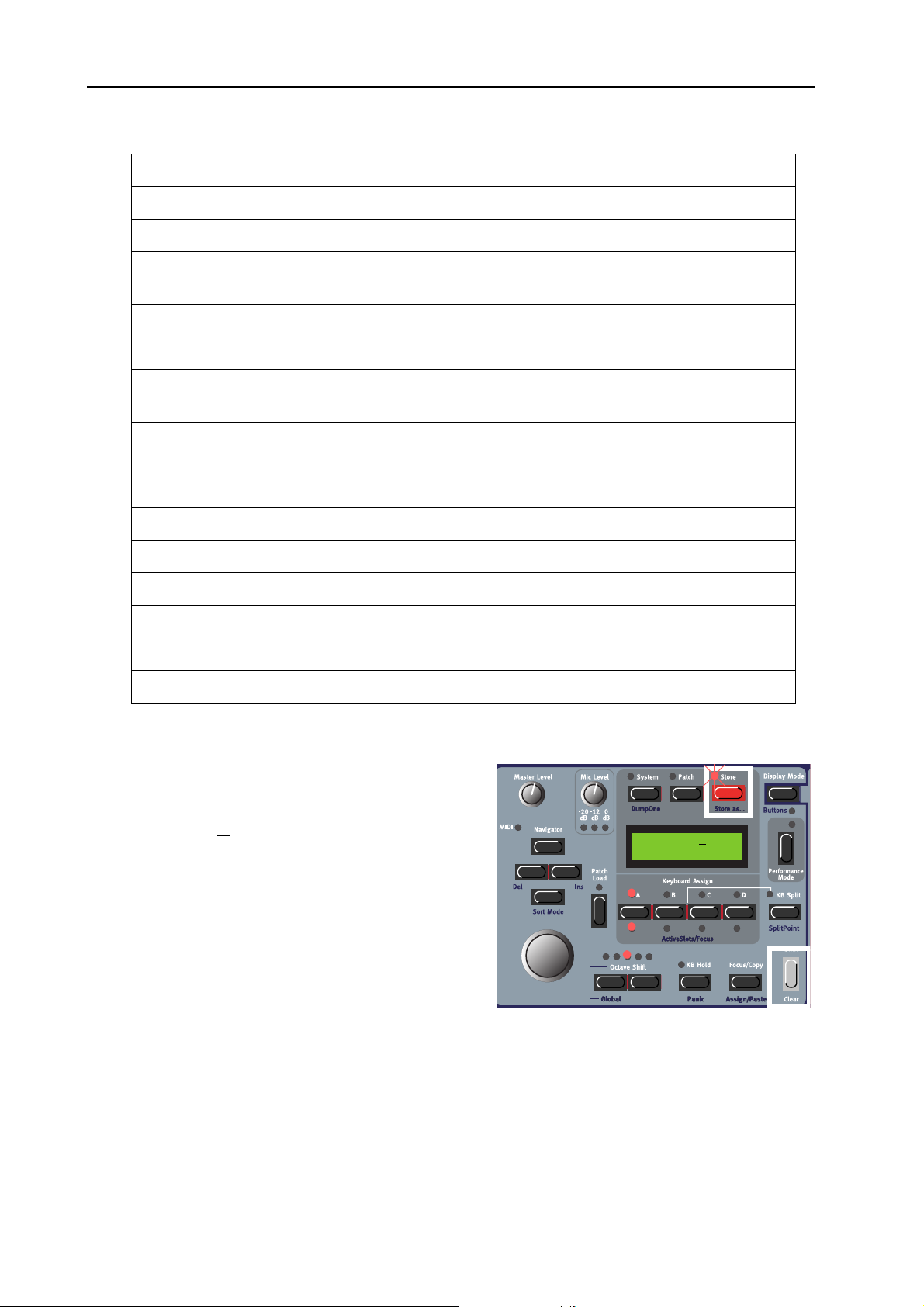
8. Working with the synth: Store a Patch NORD MODULAR G2 V1.1
CCCC
AAAATTTTEEEEGGGGOOOORRRRYYYY
Sequencer Sounds which use sequencer modules to produce melodic and/or rhythmic lines.
Bass All sorts of bass sounds
Classic Traditional “clean” analog types of polyphonic synth sounds based on the classic
Drum Drum and percussion sounds
Fantasy Melodic effects sounds and textures, often with rhythmic modulations
FX Atonal effects sounds like water, laser guns, explosions etc. Sometimes with heavy
Lead Sounds meant for lead lines. Usually monophonic sounds. Also lead “chord mem-
Organ Different types of organ sounds
EEEESSSSCCCCRRRRIIIIPPPPTTTTIIIIOOOONNNN
DDDD
waveforms
modulations.
ory” sounds
Pad Melodic polyphonic “chord” sounds with fairy slow attacks like strings, choirs etc.
Piano Different types of electric and acoustic piano emulations
Synth All sorts of melodic polyphonic synth sounds
Audio In All sorts of Patches that make use of the Audio Ins of the synth.
User1 Reserved for your own Sound Category
User2 Reserved for your own Sound Category
To store a Patch in a specific Category and change the Patch name, do like this:
1. Hold down S
LED starts flashing and the D
TORE
The S
HIFT
and press S
TORE
(Store as...).
ISPLAY
shows the current Category or, if no Category was
selected, ’N
2. Select Category with the R
o Cat’.
OTARY DIAL
. Let’s say
No name
No cat
we select ‘Acoustic’ in this example. Note that you
can’t revert to ‘No Cat’ after you have selected
another Catergory for your Patch.
Page 68
Page 73

NORD MODULAR G2 V1.1 8. Working with the synth: Copying Patches
3. Press the D
OWN NAVIGATOR
button once and
select letters for the Patch name by turning the
R
OTARY DIAL
EFT
the L
Alternatively, press and hold the D
TOR
button and select letters with the R
AL
. Each time you release the D
button the cursor in the D
. Change the cursor position with
(and R
IGHT
AVIGATOR
) N
ISPLAY
buttons.
OWN NAVIGA
OWN NAVIGATOR
advances one
OTARY DI
-
-
step.
Repeat the procedure for the entire Patch name. If
you want to delete a letter/position and thus move
all the letters to the right of the cursor one step
back, hold down SHIFT
GATOR
(DEL) button. (This function is the same as
and press the L
EFT NAVI
-
using the Delete key on a computer keyboard.) If
you want to move all letters to the right of the cursor one step forward and thus make room for more
letters, hold down S
N
AVIGATOR
(INS) button. (Press a S
HIFT
and press the R
LOT
IGHT
button to
cancel the Storing operation).
4. Press S
R
OTARY DIAL
again. The S
TORE
. Switch between Banks pressing the U
LED continues to flash. Select memory location by turning the
TORE
P/DOWN NAVIGATOR
through the memory locations, you can see the Patch names in the D
overwriting a Patch that you want to keep.
N
o name
Guitarish
Acoustic
Acoustic
buttons. As you scroll
ISPLAY
. This prevents you from
5. Press S
TORE
again to store your Patch. (To cancel the operation, press the F
OCUS/COPY
Note! If you started to save a Patch by only pressing the Store button and then change your mind and
want to change Category and/or name, you can press Shift+Store right after you pressed Store the first
time. This way you don’t have to abort the initial storing procedure but can continue right away.
CCCC
OOOOPPPPYYYYIIIINNNNGGGG
FFFF
RRRROOOOMMMM
OOOONNNNEEEE
P
P
AAAATTTTCCCCHHHHEEEESSSS
P P
MMMMEEEEMMMMOOOORRRRYYYY
LLLLOOOOCCCCAAAATTTTIIIIOOOONNNN
TTTTOOOO
AAAANNNNOOOOTTTTHHHHEEEERRRR
Copying a Patch from one memory location to another is just a variation of storing. You just change the
memory location after you pressed S
TORE
the fist time as described in “Store a Patch” on page 67.
Of course you could also copy a Patch to a new memory location and change the Patch name and/or Category. Just follow the instructions in the paragraph “Storing with new Category and/or new Patch name”
on page 67.
button.)
Page 69
Page 74

8. Working with the synth: Rename a Patch NORD MODULAR G2 V1.1
FFFF
RRRR
EEEENNNNAAAAMMMMEEEE
DDDD
EEEELLLLEEEETTTTEEEE
RRRROOOOMMMM
You can also copy a Patch from one Slot and paste it
into another Slot. Do like this:
Press and hold the F
holding it, press the S
you want to copy. Release all buttons. Press and hold
S
HIFT+FOCUS/COPY
press the destination S
Note: The copied Patch is not stored in any memory
location after this operation. It is only copied to the
new Slot’s edit buffer.
Renaming a Patch is the same as saving the Patch with a new name to the same memory location. Just
follow the instructions in the paragraph “Storing with new Category and/or new Patch name” on page 67
and select the same memory location.
Deleting Patches from the internal memory of the synth can only be done from the Editor. Please refer
to “Delete a Patch” on page 46.
OOOONNNNEEEE
AAAA
S
S
S S
AAAA
P
P
P P
LLLLOOOOTTTT
OCUS/COPY
LOT
(Paste) and while holding them
P
P
AAAATTTTCCCCHHHH
P P
TTTTOOOO
AAAANNNNOOOOTTTTHHHHEEEERRRR
button and while
button containing the Patch
LOT
button.
AAAATTTTCCCCHHHH
4:36 Synth
Dream synth
AAAA
CCCCTTTTIIIIVVVVAAAATTTTEEEE
Due to the Sound engine architecture of the Nord Modular G2, which always tries to optimize the Patch
Load and voice allocation resources, there are some things to bear in mind:
In live and sequencing situations you may want to
quickly (without any silence) switch between Patches
by simply accessing another S
Sound engine to “prepare” for this, it has to calculate
the entire Slot configuration in advance. Therefore,
you need to activate all the Slots you plan to use, with
their Patches loaded, in advance.
Activate the Slots you want to use by holding down the
S
HIFT
plan to use. The A
the total Sound engine calculation. The LED for the currently focused Slot will flash to indicate it’s selected for editing. Now, when you press another S
no silence since the Sound engine has already calculated the entire Slot configuration. If you switch between Slots which haven’t been previously enabled with the ActiveSlots/Focus function, the Sound engine has to recalculate every time you change Slot and thus cause a brief moment of silence.
SSSSEEEEVVVVEEEERRRRAAAALLLL
LOT
button and pressing the S
CTIVESLOTS/FOCUS
S
S
LLLLOOOOTTTTSSSS
S S
. In order for the
LOT
button(s) you
LED
S
4:36 Synth
Dream synth
for each active Slot will light up, indicating they’re used in
LOT
button to play another active Patch, there will be
Page 70
Page 75
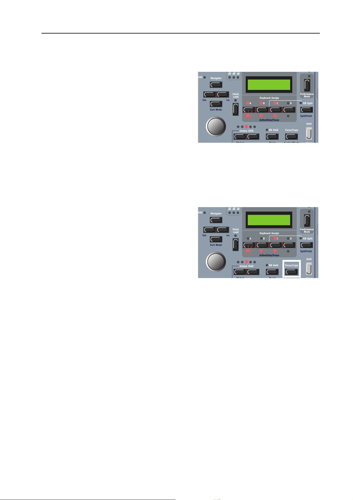
NORD MODULAR G2 V1.1 8. Working with the synth: Layering Patches
LLLL
AAAAYYYYEEEERRRRIIIINNNNGGGG
First of all you have to activate the Slots you plan to use
as described above. Then, simultaneously press the
S
LOT
buttons containing the Patches you want to layer. Alternatively, double-click the S
by one, to add them to the layer. The K
LED for each selected Slot in the layer will light
SIGN
up. The A
rently focused Slot will flash to indicate it’s selected for
editing. The Patches in the active Slots will now sound
when you play the keyboard or send MIDI Note data
on the MIDI I
by pressing another active S
ton you want to exclude from the layer. (See more about layering Patches in “Performances” on page 74).
Note that every time you load a Patch into any Slot, there will be a brief moment of silence when the
Sound engine recalculates and optimizes the Patch data.
CCCC
HHHHAAAANNNNGGGGIIIINNNNGGGG
By default, changing keyboard focus by pressing a Slot
button in a layer automatically also changes the edit focus. By ‘edit focus’ we mean the Slot which holds the
Patch currently enabled for editing from the front panel (and from the Editor). In some situations you may
want to have the edit focus on a Patch in a Slot which
is different from the Patch you’re playing from the keyboard. Then, Hold down the F
and press the desired S
the edit focus but not the keyboard focus. In the picture to the right, Slot A has edit focus and Slot C has keyboard focus.
P
P
AAAATTTTCCCCHHHHEEEESSSS
P P
4:36 Synth
Dream synth
LOT
buttons, one
EYBOARD AS
CTIVE/FOCUSED SLOTS
N
on the Global MIDI Channel (see “MIDI Glob Ch” on page 80). Change focused Slot
E
E
E E
DDDDIIIITTTT
F
F
OOOOCCCCUUUUSSSS
F F
LOT
button. This will change
LED for the cur-
LOT
button. Deselect a Slot from the layer by double-clicking the S
OCUS/COPY
BBBBUUUUTTTT
NNNNOOOOTTTT
button
-
K
K
EEEEYYYYBBBBOOOOAAAARRRRDDDD
K K
FFFFOOOOCCCCUUUUSSSS
4:36 Synth
Dream synth
LOT
but-
MMMM
OOOORRRRPPPPHHHH
The Morph function lets you continuously control defined ranges of several parameters in a Patch, using
only a single control source. This lets you produce radical changes in a sound in a very fast and easy way.
Nord Modular G2 features eight separate Morph groups per Patch. You may assign a total of 25 parameters to these 8 Morph groups in each Patch. A parameter can also be assigned so several Morph groups
(all 8 if you like), and thus be controlled differently from several sources. Also, if you use several Variations in a Patch, the Morph group assignments can be different for each Variation. The control sources
are Keyboard Velocity, Keyboard Range, Keyboard Aftertouch, Control Pedal, Sustain/Switch Pedal,
Modulation Wheel, Pitch/Control Stick and/or any A
GGGGRRRROOOOUUUUPPPPSSSS
SSIGNABLE KNOB
on the front panel.
Page 71
Page 76

8. Working with the synth: Morph groups NORD MODULAR G2 V1.1
a
a
a
AAAA
SSSSSSSSIIIIGGGGNNNN
PPPPAAAARRRRAAAAMMMMEEEETTTTEEEERRRRSSSS
TTTTOOOO
M
M
AAAA
OOOORRRRPPPPHHHH
M M
In the example below we will assign the A, D, S and R
parameters of an ADSR Envelope module to the M
W
HEEL
. However, the procedure is exactly the same for
the other parameters and Morph groups as well. First
we press the P
ATCH
button and navigate down to the
EnvADSR1 module. This figure shows the current parameter settings:
1. Press the M
TIONS
buttons. The M
2. Now, press the W
1 button). All circular LED
TION
button to the right of the V
ORPH
LED lights up.
ORPH
HEEL
Morph button (the V
GRAPHS
on the
front panel will go blank and the Wheel Morph
LED will flash.
3. Turn the parameter K
NOBS
you want to assign to
the Wheel Morph group. The first and last LED of
the Morph range will light up. A Morph range can
be either negative or positive according to your
choice. The “zero” Morph value is the parameter’s
initial setting. In this example we assign the A, D,
S, and R parameters of the EnvADSR1 module.
OD
ARIA
ARIA
GGGGRRRROOOOUUUUPPPP
-
-
EnvADSR1------ --Attack Decay
EnvADSR1------ --Attack Decay
EnvADSR1------ --Attack Decay
-------------- --Sustain Release
-------------- --Sustain Release
-------------- --Sustain Release
-----------KBG Sh
-----------KBG Sh
-----------KBG Sh
When you are ready with the assignments, release
the W
Morph button and the LED
HEEL
GRAPHS
will light up again to show the regular settings.
Now, the Wheel Morph LED will light steadily to indicate that there are parameters assigned to this
Morph group. To continue the Morph assignment, navigate to other module parameters to assign.
Then, press the M
button again and repeat the procedure.
ORPH
Note that you can also assign parameters directly from the Parameter Pages to Morph groups. In other
words, you don’t have to enter Patch Edit mode if the parameters you want to morph are already assigned
to a Parameter Page.
To change the initial parameter value(s) and thus move the entire Morph range (sector), just change the
parameter value without pressing any M
ORPH GROUP
button (just as you would change an unassigned
parameter).
The Wheel, Aftertouch, Control Pedal, Sustain Pedal and Pitch Stick Morphs will show the actual parameter values when you change the source value is the morphed parameters are currently displayed in
the A
SSIGNABLE DISPLAYS
. The Velocity and Keyboard Morphs don’t show the actual parameter values
as you play on the keyboard. It’s made this way because it gets irritating after a while to watch all flickering
LEDs as you play.
Page 72
Page 77

NORD MODULAR G2 V1.1 8. Working with the synth: Morph groups
Note: If you have assigned the same parameter to several Morph groups and control the parameter simultaneously from the different Morph group control sources, the parameter values will be added together. This means that the parameter value can go beyond the ranges set for each individual Morph
group.
Tip! If you want to enter “Morph Assign” mode without needing to hold the M
you can double-click the M
DDDD
EEEEAAAASSSSSSSSIIIIGGGGNNNN
1. Navigate to the morphed parameter you wish to deassign.
2. Press the M
Morph group will indicate their morph ranges.
3. Turn the parameter K
graph will go blank to indicate that the parameter has been deassigned from the Morph group.
To deassign all assigned parameters from a Morph group, hold down S
sponding M
EEEE
DDDDIIIITTTT
PPPPAAAARRRRAAAAMMMMEEEETTTTEEEERRRRSSSS
The Morph range will always start at the current position of the parameter. The relationship between the
setting of the parameter and the Morph range will be fixed, even if you move the setting of the parameter
after a Morph range has been set.
DDDDIIIITTTT
EEEE
Press the corresponding P
You can edit the morph range (the size of the sector) by first pressing the M
ing down the M
PPPPAAAARRRRAAAAMMMMEEEETTTTEEEERRRRSSSS
AAAA
MMMMOOOORRRRPPPPHHHHEEEEDDDD
button. Then, hold the M
ORPH
ORPH GROUP
ORPH GROUP
ORPH GROUP
NOB
you wish to deassign until it meets the initial (start) value. The LED
button (Morph Clear).
IIIINNNN
AAAA
PPPPAAAARRRRAAAAMMMMEEEETTTTEEEERRRR
ARAMETER PAGE
button and turning the morphed K
M
M
M M
button. Click again to exit Morph Assign mode.
FFFFRRRROOOOMMMM
M
M
AAAA
OOOORRRRPPPPHHHH
M M
ORPH GROUP
OOOORRRRPPPPHHHH
WWWWHHHHIIIICCCCHHHH
GGGGRRRROOOOUUUUPPPP
IIIISSSS
AAAASSSSSSSSIIIIGGGGNNNNEEEEDDDD
button to display the desired morphed parameter.
GGGGRRRROOOOUUUUPPPP
button. The parameters assigned to that
TTTTOOOO
AAAA
NOB
P
P
P P
AAAARRRRAAAAMMMMEEEETTTTEEEERRRR
.
ORPH GROUP
and press the corre-
HIFT
AAAAGGGGEEEE
P
P
P P
ORPH
button and then hold-
button
DDDDIIIITTTT
AAAA
MMMMOOOORRRRPPPPHHHHEEEEDDDD
EEEE
Press the P
You can edit the morph range (the size of the sector) by first pressing the M
ing down the M
CCCC
OOOOPPPPYYYY
The special Copy/Paste function can be used to copy an entire Morph Group with all its assigned parameters from one Morph source to another. To copy and paste a Morph Group, do like this:
First, press the M
press a M
while holding them, press the new destination M
copied and pasted to the new source.
MMMM
OOOORRRRPPPPHHHH
Each Variation in a Patch can have its own unique Morph group assignments.
ATCH
M
M
AAAA
M M
ORPH GROUP
GGGGRRRROOOOUUUUPPPPSSSS
OOOORRRRPPPPHHHH
PPPPAAAARRRRAAAAMMMMEEEETTTTEEEERRRR
button to enter Patch Edit Mode. Navigate to the parameter you wish to edit.
ORPH GROUP
GGGGRRRROOOOUUUUPPPP
ORPH
button and turning the morphed K
button. Then, press and hold the F
button. Release all buttons. Press and hold S
IIIINNNN
SSSSEEEEPPPPAAAARRRRAAAATTTTEEEE
WWWWHHHHIIIICCCCHHHH
FFFFRRRROOOOMMMM
IIIISSSS
NNNNOOOOTTTT
V
V
V V
OOOONNNNEEEE
SSSSOOOOUUUURRRRCCCCEEEE
ORPH GROUP
AAAARRRRIIIIAAAATTTTIIIIOOOONNNNSSSS
AAAASSSSSSSSIIIIGGGGNNNNEEEEDDDD
OCUS/COPY
button. Now, all parameters have been
TTTTOOOO
AAAA
NOB
TTTTOOOO
HIFT+FOCUS/COPY
PPPPAAAANNNNEEEELLLL
ORPH
button and then hold-
.
AAAANNNNOOOOTTTTHHHHEEEERRRR
button and while holding it,
K
K
K K
NNNNOOOOBBBB
(Paste) and
Page 73
Page 78

8. Working with the synth: Performances NORD MODULAR G2 V1.1
-
OOOOPPPPYYYY
CCCC
All Morph groups in a Variation are automatically copied together with the rest of the parameter values
when you copy a Variation to another Variation as described on page 66.
A
A
WWWWOOOORRRRDDDD
A A
Keyboard Morph lets you control the Morphed parameters differently depending on where on the keyboard you play. The minimum source value is the lowest key of the Nord Modular G2 keyboard when
no Octave Shift is used, i.e. note C2, and maximum is the highest key, i.e C5. When you transpose the
keyboard up or down, the Keyboard Morph range will extend beyond the set Morph limits.
MMMM
OOOORRRRPPPPHHHHIIIINNNNGGGG
It’s not possible to Morph a clock-synched parameter. You can assign and set a Morph range on a clocksynched parameter, but Morphing it will have no effect.
PPPP
EEEERRRRFFFFOOOORRRRMMMMAAAANNNNCCCCEEEESSSS
WWWW
HHHHAAAATTTT
A Performance is a complete setup (combination) of four Patches - one in each Slot. The Nord Modular
G2 has 1024 memory locations for Performances (8 Banks with128 memory locations each). Since a Performance can be quite large (around 15-20 kB), it’s not likely that you will be able to use all Performance
memory locations. The Banks should therefore be considered more like “folders” to store different
projects in. A Performance contains information about which Slots should be active, layered and also any
Keyboard Split settings. A Performance also contains information about a number of other settings. Later
in this chapter follows a detailed list of what settings are saved in a Performance.
M
M
M M
IIIISSSS
OOOORRRRPPPPHHHH
AAAABBBBOOOOUUUUTTTT
CCCCLLLLOOOOCCCCKKKK
P
P
AAAA
P P
GGGGRRRROOOOUUUUPPPPSSSS
K
K
K K
EEEERRRRFFFFOOOORRRRMMMMAAAANNNNCCCCEEEE
BBBBEEEETTTTWWWWEEEEEEEENNNN
EEEEYYYYBBBBOOOOAAAARRRRDDDD
----
SSSSYYYYNNNNCCCCHHHHEEEEDDDD
AAAARRRRIIIIAAAATTTTIIIIOOOONNNNSSSS
V
V
V V
M
M
OOOORRRRPPPPHHHH
M M
MMMMOOOODDDDUUUULLLLEEEE
????
PPPPAAAARRRRAAAAMMMMEEEETTTTEEEERRRRSSSS
Note that the edits and settings you make for each individual Patch in a Performance do not affect the
original Patch in any way. The Performance memory is completely separate from the Patch memory.
The Patches saved in a Performance are only copies of the Patches from the Patch memory.
EEEE
NNNNTTTTEEEERRRRIIIINNNNGGGG
Enter Performance mode by pressing the P
ANCE MODE
P
P
EEEERRRRFFFFOOOORRRRMMMMAAAANNNNCCCCEEEE
P P
button.
M
M
M M
OOOODDDDEEEE
ERFORM
-
OSC1---------- --|
Freq Fine
1:1
Welcome
OSC2------Freq F
Page 74
Page 79

NORD MODULAR G2 V1.1 8. Working with the synth: Performances
y
y
LLLL
OOOOAAAADDDD
AAAA
NNNNEEEEWWWW
P
P
EEEERRRRFFFFOOOORRRRMMMMAAAANNNNCCCCEEEE
P P
FFFFRRRROOOOMMMM
TTTTHHHHEEEE
IIIINNNNTTTTEEEERRRRNNNNAAAALLLL
MMMMEEEEMMMMOOOORRRRYYYY
Load the new Performance into the Slots by first turning the R
OTARY DIAL
to sele ct t he Pe rfor mance . If y ou
like you can also switch between Banks by pressing the
P/DOWN NAVIGATOR
U
button. Then load the select-
ed Performance into the Slots by pressing the P
L
OAD
button. Now, you can try out other Perform-
ATCH
1:2
Scream synth
ances of the internal memory and edit parameters as
described above. To revert to “Patch mode”, press the
P
ERFORMANCE
button.
Note that selecting a new Performance changes a lot
of parameters. This might lead to unexpected behavior!
CCCC
RRRREEEEAAAATTTTIIIINNNNGGGG
P
P
AAAA
EEEERRRRFFFFOOOORRRRMMMMAAAANNNNCCCCEEEE
P P
First of all you need to activate the Slots you plan to use for your Performance. Do this by holding S
and pressing the S
EEEELLLLEEEECCCCTTTTIIIINNNNGGGG
SSSS
LOT
AAAATTTTCCCCHHHHEEEESSSS
P
P
P P
buttons you want to include as described in “Layering Patches” on page 71.
FFFFOOOORRRR
TTTTHHHHEEEE
S
S
S S
LLLLOOOOTTTTSSSS
To select Patches as base in a Performance, do like this:
1. In Performance Mode, hold down the desired
S
LOT
button (A in this example). The S
LOT
LED
flashes to indicate that it’s the active Slot. The
D
ISPLAY
shows the name of the Patch in Slot A (if
2:9 Acoustic
CN Plucked
any).
A:EnvADSR1-- --Attack Deca
HIFT
A:EnvADSR1-- --Attack Deca
2. Select a new Patch for the Slot by holding down
A button and scrolling with the R
LOT
the S
D
IAL
. To switch between Patch Banks, hold down
A button and use the UP/D
LOT
the S
GATOR
buttons. Repeat the procedure for the other Slots.
OWN NAVI
OTARY
-
Note! Do not press the Patch Load button during this operation. The Patch is automatically
loaded to the Slot as soon as you release the Slot button.
If you want to assign or deassign a Patch in an active Slot to be controlled by the keyboard (Keyboard
Assign), double-click the S
Slot or deactivate an active Slot, Press S
EEEE
DDDDIIIITTTTIIIINNNNGGGG
P
P
AAAA
EEEERRRRFFFFOOOORRRRMMMMAAAANNNNCCCCEEEE
P P
LOT
button you want to include/exclude. If you want to include an unused
HIFT+SLOT
button.
This is done just as in Patch (non-Performance) mode as described in “Edit a Patch” on page 62. To ac-
button. The LED below it flashes to indicate it’s
tivate a Slot for editing, simply press the desired S
LOT
the currently active Slot.
Note that when you save the Performance you save edited copies of Patches within the Performance.
The original Patches (from the Patch memory) that you may have used as base for the Performance
are not affected in any way.
Page 75
Page 80

8. Working with the synth: Performances NORD MODULAR G2 V1.1
GGGG
LLLLOOOOBBBBAAAALLLL
(P
(P
EEEERRRRFFFFOOOORRRRMMMMAAAANNNNCCCCEEEE
(P (P
) P
) P
AAAARRRRAAAAMMMMEEEETTTTEEEERRRR
) P) P
P
P
P P
AAAAGGGGEEEESSSS
Each Performance can have a separate set of programmable Parameter Pages, in addition to the Parameter
Pages of each Patch in the Performance. Hold down
HIFT
S
and press the P
ATCH SETTINGS
button to ac-
Release
A:Filter2
Freq Res
B:OSC2
Freq Fine
cess Global Parameter Page 1, Column 1. Now, 8 new
-
Performance parameters can be assigned to the A
SIGNABLE KNOBS
and/or A
SSIGNABLE BUTTONS
S
. If
you want to access the Programmable Parameter Pages
of each individual Patch, hold down S
ATCH SETTINGS
the P
button again. Now, the first Pa-
HIFT
and press
rameter Page of the Patch in the focused Slot is shown
in the A
SSIGNABLE DISPLAYS
. You can freely assign module parameters from any of the Slots to the Global Parameter Pages. See “Assign parameters to panel controls” on page 64 for info on how to assign parameters to the Parameter Pages.
KKKK
EEEEYYYYBBBBOOOOAAAARRRRDDDD
S
S
S S
PPPPLLLLIIIITTTT
The Keyboard Split function allows you to split the
keyboard in two sections, each playing separate Patches. When Keyboard Split is activated, Slots A and B
will be played from the lower part of the keyboard,
2:9 Acoustic
CN Plucked
A:ADSR-Env1
Attack Decay
while Slots C and D will be played from the upper
part. The Keyboard Split function is a pure synth “performance feature” and doesn’t exist in this way in the
Editor. Activate Keyboard Split function by pressing
the KB S
PLIT
button:
EEEETTTTTTTTIIIINNNNGGGG
SSSS
TTTTHHHHEEEE
S
S
S S
PPPPLLLLIIIITTTT
P
P
P P
OOOOIIIINNNNTTTT
You set the Split Point (the key where the keyboard
should be split) by holding down S
the KB S
PLIT
button. The lowest K
HIFT
and pressing
EYBOARD SPLIT
LED above the keyboard will light up to indicate the
split position. Hold down S
PLIT
S
button again to move the split point to the next position. The next Keyboard Split LED will light
HIFT
and press the KB
up instead above the keyboard.
OOOOMMMMBBBBIIIINNNNIIIINNNNGGGG
CCCC
S
S
S S
PPPPLLLLIIIITTTT
AAAANNNNDDDD
L
L
L L
AAAAYYYYEEEERRRR
Since Slots A and B will be played from the lower part of the split point and Slots C and D from the upper
part, yo u can sp lit the ke yboard and p lay layers of two Patches on each “keyboard half”. Just s elect Pat ches
for all Slots, and activate Keyboard Split.
KKKK
EEEEYYYYBBBBOOOOAAAARRRRDDDD
Z
Z
Z Z
OOOONNNNEEEE
It’s also possible to set separate note ranges for each of the Slots in a Performance. This is done in the
System menu. Please refer to “Keyboard Zone” on page 80.
Page 76
Page 81

NORD MODULAR G2 V1.1 8. Working with the synth: Performances
SSSS
TTTTOOOORRRRIIIINNNNGGGG
P
P
AAAA
EEEERRRRFFFFOOOORRRRMMMMAAAANNNNCCCCEEEE
P P
Note! When the Nord Modular G2 is shipped from factory, Memory Protect is set to ‘On’. To be able
to store Performances, first disable the Memory Protect function. See “Memory Prot” on page 81.
TTTTOOOORRRRIIIINNNNGGGG
SSSS
1. Press the S
starts flashing.
2. Select memory location by turning the R
D
U
WWWWIIIITTTTHHHHOOOOUUUUTTTT
TORE
IAL
. Switch between Banks 1-8 by pressing the
P/DOWN NAVIGATOR
CCCCHHHHAAAANNNNGGGGIIIINNNNGGGG
TTTTHHHHEEEE
NNNNAAAAMMMMEEEE
button once. The LED above it
buttons. As you scroll
OTARY
A:ADSR-Env1
Attack Decay
Store to 1:2
Scream synth
through the memory locations, you can see the
Performance names in the D
ISPLAY
. This prevents
you from overwriting a Performance that you want
to keep.
3. Press S
TORE
again to store your Performance. (To cancel the operation, press the F
OCUS/COPY
ton.)
SSSS
TTTTOOOORRRRIIIINNNNGGGG
1. Hold down S
The LED starts flashing and the D
the name of the current Performance. Select letters
with the R
position with the L
WWWWIIIITTTTHHHH
TTTTHHHHEEEE
HIFT
OTARY DIAL
PPPPOOOOSSSSSSSSIIIIBBBBIIIILLLLIIIITTTTYYYY
and press S
TORE
and change the cursor
EFT
IGHT NAVIGATOR
and R
TTTTOOOO
CCCCHHHHAAAANNNNGGGGEEEE
(Store as...).
ISPLAY
shows
TTTTHHHHEEEE
NNNNAAAAMMMMEEEE
A:ADSR-Env1
Attack Decay
Scream synth
buttons.
but-
Alternatively, press and hold the D
TOR
button and select letters with the R
AL
. Each time you release the D
button the cursor in the D
OWN NAVIGATOR
ISPLAY
advances one step. Repeat the procedure for the entire Performance
OWN NAVIGA
OTARY DI
-
-
name. If you want to delete a letter/position and thus move all the letters to the right of the cursor one
step back, hold down S
HIFT
and press the L
EFT NAVIGATOR
(DEL) button. (This function is the same
as using the Delete key on a computer keyboard.) If you want to move all letters to the right of the
cursor one step forward and thus make room for more letters, hold down S
N
AVIGATOR
2. Press S
D
IAL
. Switch between Banks 1-8 by pressing the U
(INS) button. (Press the F
again. The LED continues flashing. Select memory location by turning the R
TORE
OCUS/COPY
button to cancel the Storing operation).
P/DOWN NAVIGATOR
through the memory locations, you can see the Performance names in the D
HIFT
and press the R
buttons. As you scroll
ISPLAY
. This prevents
IGHT
OTARY
you from overwriting a Performance that you want to keep.
3. Press S
TORE
again to store your Performance. (To cancel the operation, press the F
OCUS/COPY
but-
ton.)
The Patches you use in the Performance Slots are saved complete with all parameter settings, Keyboard
Split info and Parameter Pages (also Global) configurations when the Performance is saved. The above
Page 77
Page 82

8. Working with the synth: Performances NORD MODULAR G2 V1.1
point means that there is no need to store the Patches separately. As soon as you save the Performance,
all Patches that it uses are also saved, within the Performance. This also means that if you later change
any of your Patches, in Patch mode, the Patches in the Performances are not affected in any way.
EEEE
XXXXTTTTRRRRAAAACCCCTTTTIIIINNNNGGGG
P
P
AAAATTTTCCCCHHHHEEEESSSS
P P
FFFFRRRROOOOMMMM
P
P
AAAA
EEEERRRRFFFFOOOORRRRMMMMAAAANNNNCCCCEEEE
P P
As stated earlier, the Patches used in the Slots of a Performance are not references to regular, existing Programs, but separate Patches “on their own”. You will find several unique sounds in the factory Performances; sounds that you will not find in any of the internal Patch locations. You may want to extract such
a Patch, to save as a single Patch in the Patch memory.
XXXXTTTTRRRRAAAACCCCTTTT
EEEE
AAAA
AAAATTTTCCCCHHHH
P
P
P P
AAAANNNNDDDD
SSSSAAAAVVVVEEEE
IIIITTTT
1. Select the Performance containing the sound you want to extract.
2. Press the P
3. Press the S
ERF MODE
LOT
button to activate the Slot (A
button to exit Performance mode.
CTIVE SLOTS/FOCUS
LED is flashing) containing the
desired Patch.
4. Press S
5. Select Patch memory location by turning the R
6. Press S
TORE
. The LED above the S
U
P/DOWN NAVIGATOR
Patches in the D
TORE
ISPLAY
again to store your Patch. (To cancel the operation, press a S
TORE
button starts flashing
OTARY DIAL
. Switch between Banks by pressing the
buttons. As you scroll through the memory locations, you can see the
. This prevents you from overwriting a sound that you want to keep.
LOT
button.) The Patch is
now stored as a single Patch.
XXXXTTTTRRRRAAAACCCCTTTT
EEEE
AAAA
AAAATTTTCCCCHHHH
P
P
P P
RRRREEEENNNNAAAAMMMMEEEE
,
,
, ,
IIIITTTT
AAAANNNNDDDD
SSSSAAAAVVVVEEEE
IIIITTTT
1. Select the Performance containing the sound you want to extract.
2. Press the P
3. Press the S
ERF MODE
LOT
button to activate the Slot (A
button to exit Performance mode.
CTIVE SLOTS/FOCUS
LED is flashing) containing the
desired Patch.
4. Hold down S
5. Select Category with the R
6. Press the D
R
OTARY DIAL
Alternatively, press and hold the D
AL
. Each time you release the D
HIFT
and press S
OWN NAVIGATOR
TORE
(Store as...). The LED above the Store button starts flashing.
OTARY DIAL
.
button once and select letters for the Patch name by turning the
. Change the cursor position with the L
OWN NAVIGATOR
OWN NAVIGATOR
EFT
(and R
IGHT
AVIGATOR
) N
button and select letters with the R
button the cursor in the D
ISPLAY
buttons.
OTARY DI
advances one
step.
Repeat the procedure for the entire Patch name. If you want to delete a letter/position and thus move
all the letters to the right of the cursor one step back, hold down S
HIFT
and press the L
EFT NAVIGA
-
-
Page 78
Page 83

NORD MODULAR G2 V1.1 8. Working with the synth: The System functions
y
TOR
(DEL) button. (This function is the same as using the Delete key on a computer keyboard.) If
you want to move all letters to the right of the cursor one step forward and thus make room for more
letters, hold down S
cancel the Storing operation).
HIFT
and press the R
IGHT NAVIGATOR
(INS) button. (Press a S
LOT
button to
again. The S
7. Press S
8. Press S
DDDD
EEEELLLLEEEETTTTIIIINNNNGGGG
Deleting Performances from the internal memory of the synth can only be done from the Editor. Please
refer to “Deleting Performances in the synth” on page 56.
EEEE
XXXXIIIITTTTIIIINNNNGGGG
To exit Performance mode, press the P
You will note that the Patches you used in the latest Performance are still present in the Slots, also in Patch
mode. However, if you want to continue using them as separate Patches, you have to save each of the
Patches separately in Patch mode.
TTTT
S
S
HHHHEEEE
S S
Press the S
tions. The System menu is divided into three “sections”: parameters
which are unique for the currently focused Patch (indicated in the
ISPLAY
D
unique for the currently active Performance (indicated in the D
PLAY
global for the entire synth (indicated in the D
with the D
TORE
R
OTARY DIAL
through the memory locations, you can see the Patch names in the D
overwriting a Patch that you want to keep.
TORE
now stored as a single Patch.
P
P
P P
YYYYSSSSTTTTEEEEMMMM
YSTEM
by ‘|Pa’ in the upper right corner), parameters which are
by ‘|Pe’ in the upper right corner) and parameters which are
. Switch between Banks pressing the U
again to store your Patch. (To cancel the operation, press a S
P
P
EEEERRRRFFFFOOOORRRRMMMMAAAANNNNCCCCEEEESSSS
P P
EEEERRRRFFFFOOOORRRRMMMMAAAANNNNCCCCEEEE
FFFFUUUUNNNNCCCCTTTTIIIIOOOONNNNSSSS
button to access the system parameters and func-
OWN NAVIGATOR
LED continues to flash. Select memory location by turning the
TORE
M
M
M M
button.
OOOODDDDEEEE
ERF MODE
ISPLAY
P/DOWN NAVIGATOR
ISPLAY
button. Now you return to the regular Patch mode.
-
IS
by ‘|Sy’ in the upper right corner). Select function
buttons. As you scroll
. This prevents you from
LOT
button.) The Patch is
Sustain |Pa
O
n
ADSR-Env1
Attack Deca
PPPP
AAAATTTTCCCCHHHH
FFFFUUUUNNNNCCCCTTTTIIIIOOOONNNNSSSS
UUUUSSSSTTTTAAAAIIIINNNN
SSSS
Select if you want the Sustain Pedal functionality on or off in the
Patch. If set to On, a connected sustain pedal will control both sustain and any parameters assigned to the Switch Morph group. Select
On or Off with the R
IIIIBBBBRRRRAAAATTTTOOOO
VVVV
Select Vibrato Rate for the Patch. Range: 4.00-8.00 Hz. (The Vibrato Amount is set in the Patch Settings “menu” for the Patch. See “Ed-
it Patch Settings” on page 63).
P
P
P P
R
R
R R
EEEEDDDDAAAALLLL
AAAATTTTEEEE
(P
(P
(P (P
NNNN
O
O
O O
FFFFFFFF
/O
/O
/O/O
OTARY DIAL
))))
AAAA
.
Sustain Pedal |Pa
O
n
Vibrato Rate |Pa
6
.02 Hz
Page 79
Page 84

8. Working with the synth: The System functions NORD MODULAR G2 V1.1
PPPP
EEEERRRRFFFFOOOORRRRMMMMAAAANNNNCCCCEEEE
EEEEYYYYBBBBOOOOAAAARRRRDDDD
KKKK
Here you can set individual note ranges for each of the Slots in a Performance. Press desired S
OTARY DIAL
the R
highest note limit with the R
dure for the other Slots by pressing the corresponding S
keyboard zones. Note that these ranges are also affected by any Keyboard Split setting you have in your
Performance (see “Keyboard Split” on page 76). When you store your Performance, these settings will be
stored with it.
SSSS
YYYYSSSSTTTTEEEEMMMM
MID
MIDI S
MIDMID
Set the MIDI channel for each S
used for receiving and transmitting MIDI data. If you select ‘Off’, the
Slot will not receive or transmit any MIDI data at all. Press desired
S
LOT
repeat the procedure for the other Slots by pressing the corresponding S
formance Mode, the internal keyboard will send on all Slot’s MIDI channels that have Keyboard Assign.
MIDI L
MIDI L
MIDI LMIDI L
Turn the MIDI Local Control on or off. Select Local On to be able
to control the synth from the internal keyboard and the pedals. MIDI
data is also transmitted via the MIDI O
mode, the keyboard and pedal actions are transmitted only via MIDI
and do not control the synth itself. Local Off should be used with external sequencers if the MIDI O
jack of Nord Modular G2 is routed back, via the external sequencer, to the MIDI I
in the sequencer, “double notes” will appear when playing the keyboard in Local On mode. Select On or
off with the R
FFFFUUUUNNNNCCCCTTTTIIIIOOOONNNNSSSS
LLLLOOOOTTTT
I S
I SI S
button and set MIDI channel with the R
OOOOCCCCAAAALLLL
FFFFUUUUNNNNCCCCTTTTIIIIOOOONNNNSSSS
OOOONNNNEEEE
Z
Z
Z Z
. Press the R
HHHH
C
C
C C
OTARY DIAL
(P
(P
))))
EEEE
(P (P
LOT
button and set lower note limit with
IGHT NAVIGATOR
OTARY DIAL
(S
(S
))))
YYYY
(S (S
(A-D). The set channels will be
LOT
UT
.
. Then, repeat the proce-
button and set the
LOT
OTARY DIAL
jack. In the Local Off
Keyboard Zone |Pe
C-1
- B3
buttons. It’s also possible to have overlapping
MIDI Slot Ch |Sy
1
. Then,
LOT
234
buttons. Note that in Per-
MIDI Local |Sy
O
n
N
jack. If Echo is active
UT
MIDI G
MIDI G
MIDI GMIDI G
Here you set the Global MIDI Channel for the synth. The Global
MIDI Channel should be used for receiving MIDI note data and
control data (Mod Wheel, Aftertouch, Velocity, Aftertouch and Pedals) as well as sending and receiving MIDI Program Change messages
in Performance mode. Select Global MIDI Channel with the R
MIDI S
MIDI S
MIDI SMIDI S
Here you can set an ‘Instrument SysEx ID’. This is very useful if
you’re sending SysEx dumps of sounds from a sequencer to the Nord
Modular G2 and have several G2 synthesizers MIDI connected. Let’s
say you have two G2 synthesizers. These two instrument models have
the same ‘Manufacturer ID’ and ‘Model ID’ in the SysEx protocol. By defining separate SysEx ID’s on
each of the two synths, you will be able to “direct” the SysEx dumps from the sequencer to one of the
G2’s while the other one will ignore the dumps. Just make sure that you define a separate SysEx ID before
dumping the sounds to the sequencer. Select Instrument SysEx ID with the R
All
LLLLOOOOBBBB
YYYYSSSS
EEEE
C
C
C C
XXXX
HHHH
ID
ID
ID ID
MIDI Glob Ch |Sy
1
6
OTARY DIAL
. Range: Channel 1-16, Off.
MIDI SysEx ID |Sy
1
6
OTARY DIAL
Page 80
. Range: 1-16,
Page 85

NORD MODULAR G2 V1.1 8. Working with the synth: The System functions
LLLLKKKK
MIDI C
MIDI C
MIDI CMIDI C
Here you choose whether or not to send out MIDI Clock to the
MIDI O
only work when you use the internal Master Clock as clock source.
Select On or Off with the R
MIDI C
MIDI C
MIDI CMIDI C
Here you choose whether or not to accept external MIDI Clock signals received on the MIDI I
Master Clock of the synth will automatically sync to any incoming
MIDI Clock. Select On or Off with the R
MIDI P
MIDI P
MIDI PMIDI P
Here you select how the synth should handle Program Change and
Bank Select (Controller #32) MIDI messages. Select Off, Send (only), Receive (only) and Send and Receive with the R
EEEENNNNDDDD
S
S
S S
UT
jack of the synth. Sending out a MIDI Clock signal will
LLLLKKKK
RRRRGGGG
R
R
R R
C
C
C C
EEEECCCCVVVV
HHHHNNNNGGGG
OTARY DIAL
N
jack of the synth. If set to ‘On’, the
.
OTARY DIAL
.
OTARY DIAL
MIDI Clk Send |Sy
O
ff
MIDI Clk Recv |Sy
O
ff
MIDI Prg Chng |Sy
S
end & Receive
.
MIDI C
MIDI C
MIDI CMIDI C
Here you select how the synth should handle MIDI Controller messages. Select Off, Send (only), Receive (only) and Send and Receive
with the R
UUUUSSSSTTTT
SSSS
Different sustain pedals use different polarity to activate the sustain
switch. Select between ‘Open’ and ‘Closed’ with the R
TTTTRRRRLLLL
CCCC
Different control/expression pedals have different characteristics.
Here you can select Gain to adjust the control pedal functionality of
the synth to your specific expression pedal. Select range (x1.00x1.50) with the R
AAAASSSSTTTTEEEERRRR
MMMM
Use this function to tune the synth to other instruments. The range
is from -6 to +6 semitones and fine adjustment from -100 to +100
cents. 100 cents is one semitone. All Oscillator modules are affected
by the Master Tune function. Select tuning with the R
EEEEMMMMOOOORRRRYYYY
MMMM
Select memory protection for the entire internal Patch and Performance memory. Select On or Off with the R
YYYYNNNNTTTTHHHH
SSSS
Here you can name your synth. Select characters with the R
D
IAL
TOR
button and select letters with the R
lease the D
TTTTRRRRLLLL
OTARY DIAL
EEEEDDDD
P
P
P
P
P P
P P
EEEEDDDD
P
P
G
G
P P
G G
UUUUNNNNEEEE
T
T
T T
P
P
P P
NNNNAAAAMMMMEEEE
OOOOLLLL
AAAAIIIINNNN
RRRROOOOTTTT
.
OTARY DIAL
OTARY DIAL
.
OTARY DIAL
OTARY DIAL
.
and change the “cursor” position with the left/right N
buttons. Alternatively, press and hold the D
OTARY DIAL
OWN NAVIGATOR
button the cursor in the D
OWN NAVIGATOR
. Each time you re-
ISPLAY
MIDI Ctrl |Sy
S
end & Receive
Sust Ped Pol |Sy
.
O
pen
Ctrl Ped Gain |Sy
x1
.00
Master Tune |Sy
0
semi 0 cent
.
Memory Prot |Sy
O
ff
OTARY
AVIGA
advances one step. Repeat the procedure
Synth Name |Sy
-
M
odularG2
for the entire Synth name. If you want to delete a letter/position and thus move all the letters to the right
of the cursor one step back, hold down S
HIFT
and press the L
EFT NAVIGATOR
(DEL) button. (This func-
Page 81
Page 86

8. Working with the synth: The System functions NORD MODULAR G2 V1.1
y
tion is the same as using the Delete key on a computer keyboard.) If you want to move all letters to the
right of the cursor one step forward and thus make room for more letters, hold down S
IGHT NAVIGATOR
the R
(INS) button.
HIFT
and press
DDDD
O
O
UUUUMMMMPPPP
O O
NNNNEEEE
Hold down S
HIFT
and press the S
YSTEM
button to send a MIDI
SysEx dump of the Patch in the focused Slot, or of an entire Performance in Performance Mode. Note that an average MIDI SysEx
dump of a Patch is approximately 5 kB and that of a Performance
nearly 20 kB. This means the recording device - a sequencer, for example - must be prepared for this amount of data.
Sustain |Pa
n
O
ADSR-Env1
Attack Deca
Page 82
Page 87

NORD MODULAR G2 V1.1 9. Working with the Editor: File menu
9. W
9. WO
9. W9. W
In the Editor, the usual Windows98SE/2000/XP keyboard commands are available. The drop-down
menus can be accessed by pressing the Alt key and the underlined letter in the menu bar. The functions
in the drop-down menus can then be accessed by pressing the key corresponding to the underlined letter
in the drop-down menus.
Most of the commands can also be accessed by pressing the Ctrl key together with the letter shown next
to the command name in the drop-down lists.
ORRRRKKKKIIIIN
OO
NG
NN
G
W
GG
WIIIITTTTH
WW
H
HH
T
TH
TT
HE
E
HH
EE
Editor
Editor
EditorEditor
FFFF
IIIILLLLEEEE
NNNN
NNNN
OOOO
NNNN
MMMMEEEENNNNUUUU
P
P
EEEEWWWW
Creates a new, empty Patch window. If connected to the synth, the currently active Slot will be cleared
to host your new Patch. See “Creating your first Patch” on page 36 for info on how to create a Patch.
EEEEWWWW
Creates 4 new, empty Patch windows. If connected to the synth, all 4 Slots will be automatically activated
and cleared to host your new Performance. Slot A will be assigned to the keyboard. The synth will also
switch to Performance Mode. See “Creating a Performance in the Editor” on page 54.
PPPPEEEENNNN
Brings up the file selector and allows you to open a Patch or Performance file from disk. Select between
Patch and Performance files from the ‘Files of type’ drop-down selector. Select a file and click Open to
open and download the Patch/Performance to the Slot(s) in the synth. Note that if you open a Patch in
Performance mode with the synth connected, the selected Patch will be opened and downloaded in
Slot A and all other Slots will be cleared.
EEEEWWWW
Creates a new, empty Patch window in a selectable Slot of the connected synth, or in Performance Mode.
If connected to the synth, the selected Slot will be cleared to host your new Patch. See “Creating your
first Patch” on page 36.
AAAATTTTCCCCHHHH
P P
P
P
EEEERRRRFFFFOOOORRRRMMMMAAAANNNNCCCCEEEE
P P
T
T
OOOO
T T
OOOO
T
T
PPPPEEEENNNN
Brings up the file selector and allows you to open a Patch file from disk and download to a selectable Slot.
Select a file and click Open to open and download the Patch to the selected Slot in the synth. This command is useful when you select Patches when creating a Performance.
T T
OOOO
Page 83
Page 88

9. Working with the Editor: Edit menu NORD MODULAR G2 V1.1
SSSS
AAAAVVVVEEEE
This command will save the current Patch or Performance to a storage disk on the computer. If the Patch
or Performance wasn’t opened from the computer using the File|Open command (see above) or if you
changed the Name in the Toolbar, you will be prompted for a file name and destination folder. Patches
that are saved from the Editor automatically gets the extension ‘.pch2’ and Performances ‘.prf2’.
SSSS
SSSS
SSSS
SSSS
A
A
AAAAVVVVEEEE
This command will prompt you for a file name and destination folder before saving the Patch or Performance to disk. This is useful for renaming a Patch file before saving it, leaving any original Patch intact
on the disk. Patches that are saved from the Editor automatically gets the extension ‘.pch2’ and Performances ‘.prf2’.
AAAAVVVVEEEE
This command will save all open Patches and/or Performances to a storage disk on the computer. If a
Patch or Performance has not been saved before, you will be prompted for a file name. Patches that are
saved from the Editor automatically gets the extension ‘.pch2’ and Performances ‘.prf2’.
AAAAVVVVEEEE
This command will let you save a Patch from a selectable Slot to disk. You will also get the opportunity
to rename the Patch file before saving it, leaving any original Patch intact on the disk. Patches that are
saved from the Editor automatically gets the extension ‘.pch2’. This command is useful if you want to
extract a Patch from a Performance and save it as a single Patch on the computer.
AAAAVVVVEEEE
This command will save the current Patch as an InitPatch to a storage disk on the computer. An InitPatch
can be used as a “template” Patch to recall instantly by pressing the Init buttons in the Toolbar (see “Init
1&2” on page 97).
A A
A
A
A A
F
F
F F
I
I
I I
SSSS
LLLLLLLL
RRRROOOOMMMM
NNNNIIIITTTT
PPPP
AAAATTTTCCCCHHHH
RRRR
EEEECCCCEEEENNNNTTTT
Here you can choose to open any of the most recently opened Patches.
QQQQ
UUUUIIIITTTT
Quits the Editor software. Any unsaved Patches will automatically be deleted. Closing a Patch in the
Editor or quitting the Editor will not remove Patches that have been downloaded to a Slot in the synth.
EEEE
DDDDIIIITTTT
UUUU
NNNNDDDDOOOO
Click to undo your latest operations/commands.
RRRR
EEEEDDDDOOOO
Click to step back through the latest Undo operations. Works like a reversed ‘Undo’ function.
Page 84
F
F
F F
MMMMEEEENNNNUUUU
IIIILLLLEEEESSSS
Page 89

NORD MODULAR G2 V1.1 9. Working with the Editor: Patch menu
CCCC
UUUUTTTT
Cuts out one or several modules, including their common cable connections and parameter settings, and
places in the clipboard memory.
CCCC
OOOOPPPPYYYY
Copies one or several modules, including their common cable connections and parameter settings, and
places in the clipboard memory.
PPPP
AAAASSSSTTTTEEEE
Pastes one or several modules, including their common cable connections and parameter settings, that
previously have been cut or copied to the clipboard memory. The Paste command results in a cursor with
a small ‘+’ sign attached to it. Place the cursor where you want in the Patch window and click to paste the
module(s).
CCCC
LLLLEEEEAAAARRRR
Deletes one or several selected modules (and their mutual cable connections) from the Patch window.
PPPP
SSSS
PPPP
AAAATTTTCCCCHHHH
PPPP
AAAASSSSTTTTEEEE
EEEELLLLEEEECCCCTTTT
AAAATTTTCCCCHHHH
P
P
AAAARRRRAAAAMMMMSSSS
P P
This command should be used if you only want to paste a copied module parameter values to another
module of the same type. You can also select several modules in one Variation, select Copy and then Paste
Params in another Variation.
A
A
LLLLLLLL
A A
Selects all modules in the most recently used section of the Patch window for clearing, copying, moving
etc.
MMMMEEEENNNNUUUU
S
S
EEEETTTTTTTTIIIINNNNGGGGSSSS
S S
Opens up the Patch Settings floating
window. The Patch Settings parameters can be different for different Variations. (These functions are also
available for editing on the synth if
you press the P
ton. See “Edit Patch Settings” on
page 63).
ATCH SETTINGS
but-
SSSS
UUUUSSSSTTTTAAAAIIIINNNN
Select if a sustain pedal/foot switch connected to the S
Modular G2 should act as a Sustain pedal and On/Off switch or only as an On/Off switch.
Note! If you use it only as an on/off switch (the ‘Off’ alternative), you have to assign the switch to
module parameters in a Patch to the Foot Switch Morph group (see “Morph groups” on page 51).
P
P
P P
EEEEDDDDAAAALLLL
USTAIN PEDAL
input on the rear panel of Nord
Page 85
Page 90

9. Working with the Editor: Patch menu NORD MODULAR G2 V1.1
CCCCTTTTAAAAVVVVEEEE
OOOO
Here you select the octave setting of the Patch. This information is saved with the rest of the Patch data
in the Patch. Note that this setting is active only if you play the Patch from a Nord Modular G2 keyboard
version.
RRRRPPPPEEEEGGGGGGGGIIIIAAAATTTTOOOORRRR
AAAA
Select Period (sync division) for the Arpeggiator in relation to the Master Clock rate with the knob. Activate/stop the Arpeggiator with the radio buttons below the knob. Note that the Master Clock doesn’t
have to be active for the Arpeggiator to run. Select Direction with the right knob and Range with the
radio buttons below the knob.
The Arpeggiator uses MIDI Song Position Pointer when synched to an external MIDI Clock, which
means that if you record an arpeggio in an external sequencer, it will always play back the pattern exactly
the same way it was recorded - even if you start the sequencer in the middle of the sequence.
IIIIBBBBRRRRAAAATTTTOOOO
VVVV
This is a separate vibrato which affects all modules in the Patch set to Keyboard Tracking. Set the Vibrato
amount, in cents of a semitone, with the knob and select control source (Aftertouch, Mod Wheel or Off)
with the radio buttons below the knob. Set the Vibrato rate with the knob below the radio buttons.
LLLLIIIIDDDDEEEE
GGGG
The Glide function is mainly intended for use in mono or legato (see “Voice Mode” on page 99). The
glide characteristics can be described as “constant rate”. “Constant rate” means that the greater the “distance” between two subsequent notes, the longer the glide time. Turn the knob to adjust the glide rate
and press the radio buttons to select glide mode. ‘Normal’ means the glide is always active and ‘Auto’ that
glide is active only when you play legato (you press a new key before you release the previous key).
S
S
S S
HHHHIIIIFFFFTTTT
Note: If you use Glide in polyphonic mode, the glide will be unpredictable and perceived as more or
less random. This is because the glide is between voices rather than between keys. The glide will therefore be from the available voices’ latest note values to the new notes rather than from the previously
pressed keys.
BBBB
EEEENNNNDDDD
Set the Pitch bend range, in semitones, with the knob. The pitch bend will affect all modules in the Patch
set to Keyboard Tracking when you bend the P
Switch on/off the pitch bend function with the radio buttons below the knob.
TTTT
EEEEXXXXTTTTPPPPAAAADDDD
Brings up the Textpad floating window. Here you can type in text (description, comments s etc.) about
the Patch.
DDDD
EEEELLLLEEEETTTTEEEE
Select this function to clear all unused modules in the Patch. This is useful if you have edited an existing
Patch and want to get rid of any superfluous modules.
DDDD
OOOOWWWWNNNNLLLLOOOOAAAADDDD
Brings up a dialog box in which you can choose to download the currently active Editor Patch to a selectable Slot in the connected synth.
U
U
NNNNUUUUSSSSEEEEDDDD
U U
T
T
T T
OOOO
S
S
S S
M
M
OOOODDDDUUUULLLLEEEESSSS
M M
LLLLOOOOTTTT
ITCH STICK
or receive pitch bend data from MIDI.
Page 86
Page 91

NORD MODULAR G2 V1.1 9. Working with the Editor: Performance menu
PPPP
EEEERRRRFFFFOOOORRRRMMMMAAAANNNNCCCCEEEE
PPPP
EEEERRRRFFFFOOOORRRRMMMMAAAANNNNCCCCEEEE
Brings up the Performance Settings floating
window. Here you can edit the common Performance parameters.
AAAAMMMMEEEE
NNNN
Type in the Performance name and press Enter. The name will also be shown in the ‘Perf’
display box in the Toolbar.
LLLLOOOOTTTTSSSS
SSSS
Click in the check boxes for each of the Slots
you want to include in the Performance.
EEEEYYYYBBBBOOOOAAAARRRRDDDD
KKKK
Click in the check boxes for each of the Slots you want to play from the internal keyboard of the synth
and/or respond to MIDI Note data on the Global MIDI Channel (see “MIDI Settings” on page 88).
OOOOLLLLDDDD
HHHH
Click in the check box to activate Keyboard Hold for each of the Slots in the Performance.
NNNNAAAABBBBLLLLEEEE
E
E
E E
MMMMEEEENNNNUUUU
S
S
EEEETTTTTTTTIIIINNNNGGGGSSSS
S S
EEEEYYYYBBBBOOOOAAAARRRRDDDD
KKKK
Activate the Keyboard Range function by clicking in the Keyboard Range check box. Set any keyboard
note ranges for each of the Slots in the Performance. It’s possible to have overlapping keyboard ranges for
several Slots if you like. If the Keyboard Range function is not active, all enabled Slots will respond to
notes in the entire MIDI note range (C-1 to G9).
AAAASSSSTTTTEEEERRRR
MMMM
Here you can select the Master Clock Rate for your Performance. You can also select whether to have the
Master Clock active or not when you upload your Performance by clicking in the Stop or Run box.
DDDD
OOOOWWWWNNNNLLLLOOOOAAAADDDD
If you have been working on a couple of Performances in Local mode (synth unconnected) and you want
to download one of the Performances after having established contact with the synth, you can use the
Download command.
SSSS
YYYYNNNNTTTTHHHH
SSSS
YYYYNNNNTTTTHHHH
MMMMEEEENNNNUUUU
S
S
S S
The Synth Settings window provides you with functions that apply to all Patches and Performances loaded to the four Slots of the synth. Any settings that you make will be activated instantly and automatically
stored in the synth when you click the OK button. If you press Cancel, all parameters will revert to their
AAAANNNNGGGGEEEE
R
R
R R
LLLLOOOOCCCCKKKK
C
C
C C
EEEETTTTTTTTIIIINNNNGGGGSSSS
Page 87
Page 92

9. Working with the Editor: Synth menu NORD MODULAR G2 V1.1
original settings. (Some of these functions are also available for editing from the synth if you press the
S
YSTEM
button).
AAAAMMMMEEEE
NNNN
Type in a name for your connected synth and press Enter. This is especially useful if you run several Nord
Modular G2 synthesizers from the Editor. The name will also be displayed in the Synth Name display
box in the Toolbar.
MIDI
MIDI
MIDI MIDI
CCCCHHHHAAAANNNNNNNNEEEELLLL
Set the MIDI channel for each Slot. This channel will be used for reception and transmission of MIDI
messages.
MIDI Active check box:
Click in the corresponding check box to activate the Slot to receive and transmit MIDI messages.
OOOOCCCCAAAALLLL
LLLL
O
O
O O
NNNN
Click the Local On check box to turn the MIDI Local Control on. Select Local On to be able to control
the synth from the internal keyboard and the pedals. MIDI data is also transmitted via the MIDI O
UT
jack. In the Local Off mode, the keyboard and pedal actions are transmitted only via MIDI and do not
control the synth itself. Local Off should be used with external sequencers if the MIDI O
Modular G2 is routed back, via the external sequencer, to the MIDI I
N
jack. If Echo is active in the se-
UT
jack of Nord
quencer, “double notes” will appear when playing the keyboard in Local On mode.
MIDI S
MIDI S
MIDI SMIDI S
EEEETTTTTTTTIIIINNNNGGGGSSSS
Global Channel:
Here you set the Global MIDI Channel for the synth. The Global MIDI Channel should be used for
sending and receiving MIDI note data and for sending control data (Mod Wheel, Aftertouch, Velocity,
Aftertouch and Pedals) as well as sending and receiving MIDI Program Change messages in Performance
mode. Select Global MIDI Channel by clicking the arrow buttons.
SysEx ID:
Here you can set an ‘Instrument SysEx ID’. This is very useful if you’re sending SysEx dumps of sounds
from a sequencer to the Nord Modular G2 and have several G2 synthesizers MIDI connected. Let’s say
you have two G2 synthesizers. These two instrument models have the same ‘Manufacturer ID’ and ‘Model ID’ in the SysEx protocol. By defining separate SysEx ID’s on the two synths, you will be able to “direct” the SysEx dumps from the sequencer to one of the G2’s while the other one will ignore the dumps.
Just make sure that you define a separate SysEx ID before dumping the sounds to the sequencer. Select
Instrument SysEx ID by clicking on the arrow buttons.
Page 88
Page 93

NORD MODULAR G2 V1.1 9. Working with the Editor: Synth menu
Send Clock:
UT
Here you choose whether or not to send out MIDI Clock to the MIDI O
out a MIDI Clock signal will only work when you use the internal Master Clock as clock source.
Ignore External Clock:
Here you choose whether or not to accept external MIDI Clock signals received on the MIDI I
the synth. If unchecked, the Master Clock of the synth will automatically sync to any incoming MIDI
Clock.
Controllers: Receive and Send:
Here you select how the synth should handle MIDI Controller messages. Select Off, Send and Receive
by clicking in the respective check boxes.
Program Change:
Here you select how the synth should handle Program Change and Bank Select (Controller #32) MIDI
messages. Select Off, Send and Receive by clicking in the respective check boxes.
UUUUNNNNEEEE
TTTT
Master Tune:
Use this function to tune the synth to other instruments. The range is from -6 to +6 semitones and fine
adjustment from -100 to +100 cents. 100 cents is one semitone. All Oscillator modules are affected by
the Master Tune function. Select tuning with the respective arrow buttons.
Global Octave Shift:
Click in the check box to activate Global Octave Shift which means that the octave shift will affect all
Slots when controlled from the internal keyboard. Set octave shift range (-2 to +2 octaves) by clicking in
the corresponding box.
jack of the synth. Sending
N
jack of
OOOONNNNTTTTRRRROOOOLLLL
CCCC
Different control/expression pedals have different characteristics. Here you can select Gain to adjust the
control pedal functionality of the synth to your specific expression pedal. Select range (x1.00-x1.50) with
the arrow buttons.
IIIILLLLEEEE
FFFF
Memory Protect:
Select memory protection for the entire internal Patch and Performance memory by clicking in the check
box.
Sort By:
Select if you want Patches in the internal memory of the synth to be displayed by Program Number, Alphanumerical or by Category by clicking the desired box. See “Search for and load a Patch” on page 61
for more info on how to use the different Sort Modes on the synth.
EEEEDDDDAAAALLLL
PPPP
Different sustain pedals use different polarity to activate the sustain switch. Select between ‘Open’ and
‘Closed’ by clicking the desired box.
UUUU
PPPPLLLLOOOOAAAADDDD
This command will upload the Patch from the currently active Slot in the synth to the Editor. This is
useful if you have closed the Patch in the Editor earlier and want to edit the Patch in the Slot again. A
new Patch window will be created for the uploaded Patch.
PPPPEEEEDDDDAAAALLLL
OOOOLLLLAAAARRRRIIIITTTTYYYY
P
P
P P
A
A
A A
CCCCTTTTIIIIVVVVEEEE
GGGGAAAAIIIINNNN
S
S
S S
LLLLOOOOTTTT
Page 89
Page 94
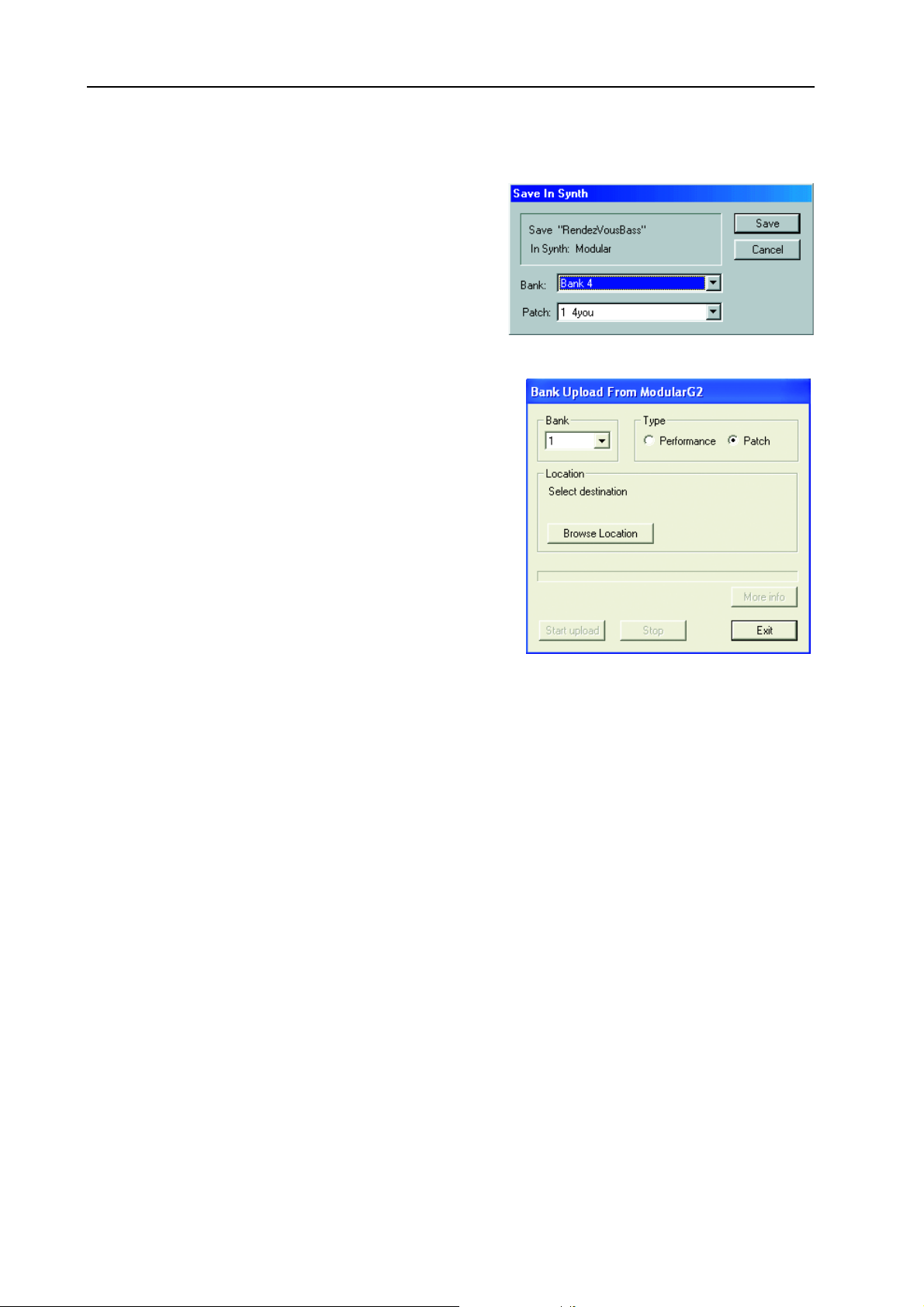
9. Working with the Editor: Synth menu NORD MODULAR G2 V1.1
SSSS
BBBB
I
I
S
AAAAVVVVEEEE
This function lets you save the Patch or Performance of
the active Patch window in any of the synthesizer’s
memory locations.
Select Bank and Patch location from the drop-down
menus. Click Save to execute and exit the dialog box, or
Cancel to exit without saving.
AAAANNNNKKKK
This feature is a quick way of saving a complete Patch or
Performance bank from the synth memory to disk without
needing to upload and save each Patch/Performance separately.
1. Select Type (Patch or Performance) and which bank to
2. Click Browse Location to select a destination folder on
3. In the ‘File name’ field, you can type in your own file
S
NNNN
I I
U
U
U U
upload (1-32 for Patches or 1-8 for Performances).
the computer.
name. By default, a Patch file is named PatchBank#
and a Performance Bank PerfBank# with the # representing the Bank number you have selected to upload.
Click Save. Now all sounds of the selected bank are saved individually together with a Patch list file
with the extension ‘.pchList'. The original memory location of each Patch is also saved with the ‘List’
file, so you can download them to the correct memory location later. As the sounds are uploaded
from synth, a progress bar indicates the elapsed time.
YYYYNNNNTTTTHHHH
S S
PPPPLLLLOOOOAAAADDDD
(F
(F
(F (F
RRRROOOOMMMM
M
M
OOOODDDDUUUULLLLAAAARRRR
M M
))))
Page 90
Tip!
Don’t save several Bank files in the same folder on the computer. The Bank file is saved together with
all individual Patch/Performance files. If several Bank files should contain the same Patch/Performance name(s), these files will be renamed with a post-fix number and could cause confusion when
downloading the Bank files back to the synthesizer. To avoid this problem, save each Bank file in a
separate folder on the computer.
Page 95

NORD MODULAR G2 V1.1 9. Working with the Editor: Synth menu
BBBB
D
D
AAAANNNNKKKK
1. Select source by clicking on one of the two buttons:
2. Select which bank (1-32 for Patches or 1-8 for Performances) to replace with your selected bank.
OOOOWWWWNNNNLLLLOOOOAAAADDDD
D D
‘Browse for Bank file’ lets you select a Bank file (.pchList) previously saved on the computer. Browse and select the pchList file you want to download to a bank in
the synth.
‘Browse for folder’ lets you select a folder containing
separate Patch or Performance files. The folder doesn’t
have to contain a pchList file. The sound files of the selected folder will be downloaded to the synth in alphabetical order. If a folder should contain more than 128
sound files the “overflowing” files will be ignored. Note
that the folder could also contain other file types, but
only Patch or Performance files will be downloaded to
the synth.
If you selected ‘Browse for Bank file’, click Open to select the file and prepare for downloading the
Patches or Performances to their original memory location within the selected bank.
(T
(T
(T (T
OOOO
M
M
M M
OOOODDDDUUUULLLLAAAARRRR
))))
If you selected ‘Browse for folder’, click OK to select the folder and prepare for downloading the
Patches or Performances, in alphabetical order, to the selected bank.
3. Click the ‘Start download’ button. A progress bar indicates the elapsed time as the files are stored in
the Nord Modular G2 internal memory. They will remain in the internal memory as if they were
stored one by one using the S
Editor.
Note!
The entire memory bank you chose to download to will be overwritten in the Nord Modular G2 synthesizer. Even if the bank you download from the computer doesn’t contain Patches/Performances in
all memory locations, all previously stored sounds in the Nord Modular G2 synthesizer bank will be
erased. Therefore, it could be wise to consider the banks in the synthesizer more like folders on the
computer. When you download an entire bank to the synthesizer it would be similar to deleting and
replacing a folder on the computer, i.e. the whole content of the bank (folder) would be erased and
replaced.
SSSS
C
C
EEEENNNNDDDD
Use this command to send all assigned MIDI Controller values to the MIDI OUT of the synthesizer. This
is very useful if you are recording in a sequencer program and want to make sure the sound sounds exactly
as you want.
OOOONNNNTTTTRRRROOOOLLLLLLLLEEEERRRR
C C
TORE
S
S
NNNNAAAAPPPPSSSSHHHHOOOOTTTT
S S
button or the ‘Store’ function of the Browser (see page 94) in the
Page 91
Page 96

9. Working with the Editor: Setup menu NORD MODULAR G2 V1.1
SSSS
EEEETTTTUUUUPPPP
OOOO
PPPPTTTTIIIIOOOONNNNSSSS
MMMMEEEENNNNUUUU
The functions in this dialog box affects the configuration of the Editor. The parameters are automatically
saved when you exit the Options window by clicking
OK.
AAAABBBBLLLLEEEE
CCCC
This is where you can adjust the appearance of the Patch
cables in the Editor. Choose between Straight 3D,
Curved 3D, Straight Thin and Curved Thin.
NNNNOOOOBBBB
KKKK
Here you select if you want the knob and slider parameters in the Editor Patch window to respond to
Circular, Horizontal or Vertical motions with the mouse.
MMMM
Click this check box to enable Morph group assignment of module parameters by double-clicking the
parameter(s). If unchecked, you have to Ctrl-click a parameter (or right-click and select from pop-up) to
assign it to a Morph group.
OOOORRRRPPPPHHHH
SSSSTTTTYYYYLLLLEEEE
CCCCOOOONNNNTTTTRRRROOOOLLLL
WWWW
OOOOUUUUBBBBLLLLEEEE
/D
/D
/D/D
C
C
C C
LLLLIIIICCCCKKKK
TTTT
OOOOOOOOLLLLSSSS
PPPP
AAAARRRRAAAAMMMMEEEETTTTEEEERRRR
MMMMEEEENNNNUUUU
P
P
AAAAGGGGEEEESSSS
P P
This function activates the
Parameter Pages floating
window. The Parameter
Pages window is a graphical
-
and B
S
-
UT
. Any assigned module parameters show up with their name and current value
K
NOB
on the synth’s front panel, the
representation of the A
SIGNABLE KNOBS
TONS
of the synth’s front
panel. The Parameter Pages
gives you both visual indication and the possibility to edit the parameters currently assigned to an A
SIGNABLE KNOB/BUTTON
in the corresponding display box.
Click-hold an assigned knob in the Parameter Pages window and change its value, just like you would
change a module parameter. As you can see, the assigned module parameter will change its value, also
visually, when the knob is changed. If you turn an ASSIGNABLE
knob in the Parameter Pages window and the corresponding module parameter will change, also visually.
Change Parameter Page by clicking on another Page and/or Column button. In Performance mode you
can also choose to display the Global Parameter Pages by clicking the Global Pages button. See “The Pa-
rameter Pages window” on page 48 for info on how to assign module parameters to the Parameter Pages.
-
S
Page 92
Page 97

NORD MODULAR G2 V1.1 9. Working with the Editor: Tools menu
PPPP
AAAARRRRAAAAMMMMEEEETTTTEEEERRRR
Brings up the Parameter Overview floating window which displays all Parameter Pages at once.
It’s also possible to assign module parameters to any of the
knobs/buttons in this window by
click-holding a display box and
dragging and dropping on a
module parameter in the Patch
window. If you like, you can also
move parameter assignments by
click-holding on a display box
and then dragging the cursor to
another display box and releasing
the mouse button. Display the
Global Pages by clicking the
Global Pages button to the top
right of the window.
VVVV
IIIIRRRRTTTTUUUUAAAALLLL
This activates the Virtual Keyboard window. This window can
be used to play a Patch without
using the synth keyboard. Click
on the keys of the Virtual Keyboard to play single notes. The selected note will be indicated by a black
dot on the corresponding key. The note will sustain if you keep the mouse button depressed, just like
pressing a key on a real keyboard.
You can expand the keyboard to cover the whole MIDI note range simply by placing the cursor on either
side of the window frame. When the double-arrow appears, click-drag horizontally to desired size. You
can also show/hide the button bar by resizing the Virtual Keyboard window.
O
O
O O
K
K
EEEEYYYYBBBBOOOOAAAARRRRDDDD
K K
VVVVEEEERRRRVVVVIIIIEEEEWWWW
The four buttons to the left are used to scroll up and down the keyboard, either one octave (the doublearrow buttons) or one note (the single-arrow buttons) at a time.
Click on the ‘Drone’ button to make the next played note start sounding “infinitely”. Click the Drone
button again to disengage.
Click on the ‘Repeat’ button to make the last played note play repeatedly. Click the Repeat button again
to disengage.
Page 93
Page 98
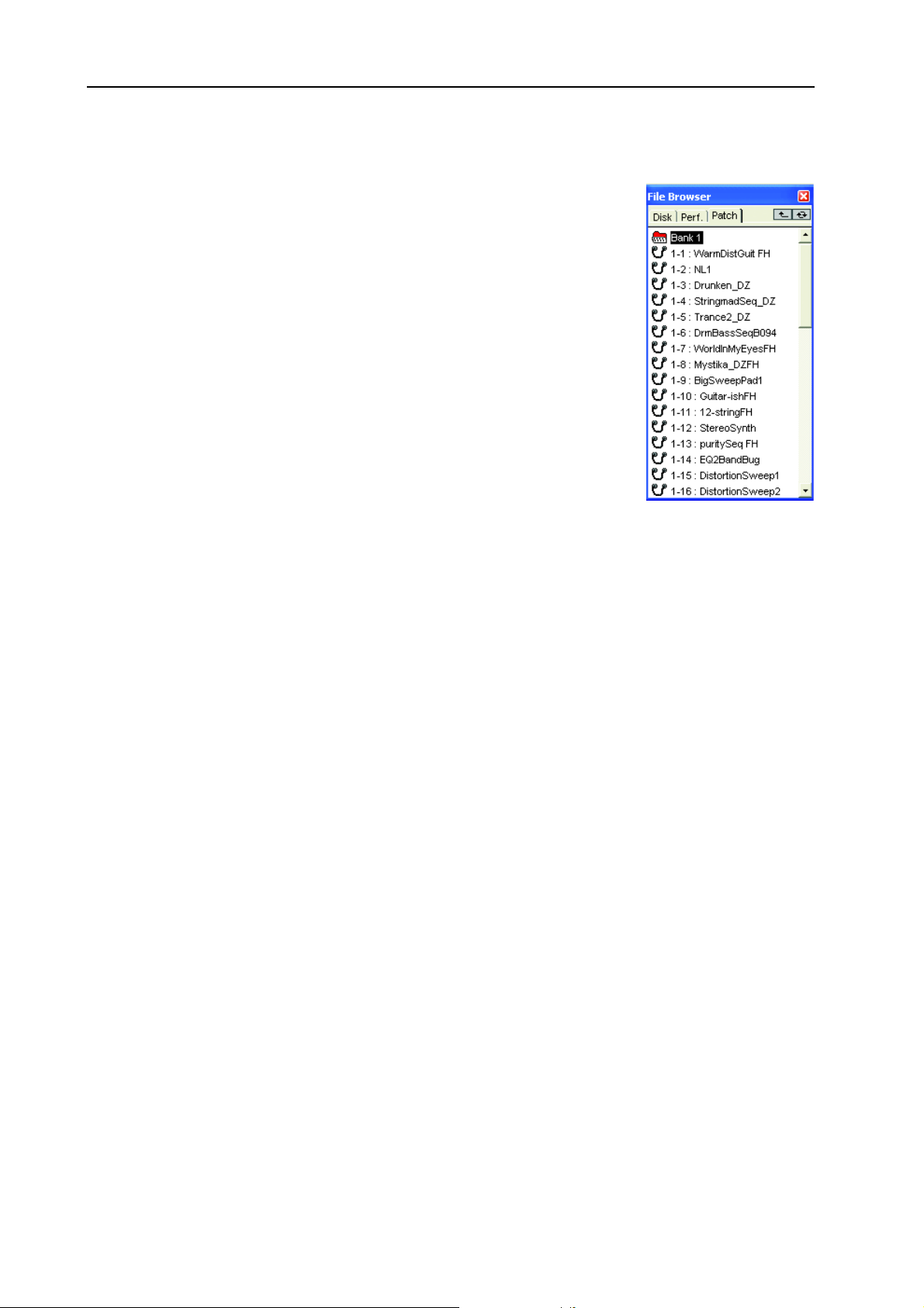
9. Working with the Editor: Tools menu NORD MODULAR G2 V1.1
FFFF
B
B
IIIILLLLEEEE
This function activates the File Browser floating window. The File Browser
gives a very good overview of all Patches and Performances currently stored
in the internal memory of the connected synth, as well as of Patches and Performances stored on the computer. The Patch and Perf tabs of the File Browser are automatically updated as soon as you perform any of the operations
described below, even if they are done from the synth’s front panel. The File
Browser can be used to save and load Patches and Performances both from
disk and the internal memory of the synth.
There are three tabs in the File Browser window:
DDDD
Click on the Disk tab to view folders and Patch/Performance files stored on
the computer. Double-click on a folder to step down one level in the hierarchy. Click the “arrow up” button to the upper right corner to step up one level in the hierarchy. Click the refresh (double arrows) button to rescan disks
and/or folders to update the Disk tab contents list.
RRRROOOOWWWWSSSSEEEERRRR
B B
IIIISSSSKKKK
Load a Patch or Performance to active Slot(s):
Double-click on a Patch or Performance file to automatically load the Patch/Performance to the active
Slot(s) in the synth and open up the Patch/Performance in the Editor Patch window. This is the same as
using File|Open. You can also use the Up and Down arrow keys to select Patch/Performance and load by
pressing Enter.
Load Patch or Performance to Slot or store in internal memory:
By right-clicking on a Patch in the Disk tab you can choose to either load the selected Patch to any of the
Slots of the connected synth and open the Patch in the Editor Patch window, or to save the selected Patch
in an internal memory location. The last function is exactly the same as storing a Patch using the S
button and the R
AAAATTTTCCCCHHHH
PPPP
Click on the Patch tab to view Patch Banks and Patches stored in the internal memory of the connected
synth.
Load a Patch to active Slot:
Double-click on a Patch to automatically load the Patch to the active Slot in the synthesizer and open up
the Patch in the Editor Patch window. This function is exactly the same as loading a Patch using the
P
ATCH LOAD
from memory” on page 61). You can also use the Up and Down arrow keys to select Patch and load by
pressing Enter. You can also open and close the content of an entire Bank by clicking the Bank icon or
selecting it (with the arrow keys or the mouse) and pressing Enter.
OTARY DIAL
button and the R
on the Nord Modular G2 front panel (see “Store a Patch” on page 67).
OTARY DIAL
on the Nord Modular G2 front panel (see “Load a Patch
TORE
Store or delete Patch from internal memory:
By right-clicking on a Patch in the Patch tab you can choose to either store the Patch of the active Slot
in the selected memory location, or to delete the selected Patch from its memory location, or change Sort
Mode.
Page 94
Page 99

NORD MODULAR G2 V1.1 9. Working with the Editor: Tools menu
Store Patch of active Slot to a selected bank:
By right-clicking on a Bank icon in the Patch tab you can choose to store the Patch of the active Slot in
one of the selected bank’s memory locations, or delete the entire Bank with all its Patches, or change Sort
Mode.
EEEERRRRFFFF
....
PPPP
Click on the Perf tab to view Performance Banks and Performances stored in the internal memory of the
connected synth.
Load a Performance:
Double-click on a Performance to automatically load the Performance to the Slots in the synthesizer and
open up the Performance in the Editor. This function is exactly the same as loading a Performance using
ATCH LOAD
the P
Performance from the internal memory” on page 75). You can also use the Up and Down arrow keys to
select Performance and load by pressing Enter. You can also open and close the content of an entire Bank
by clicking the Bank icon or selecting it (with the arrow keys or the mouse) and pressing Enter.
Store or delete Performance from internal memory:
By right-clicking on a Performance in the Performance tab you can choose to either store the Performance
of the active Slots in the selected memory location, or to delete the selected Performance from its memory
location, or change Sort Mode.
button and the R
OTARY DIAL
on the Nord Modular G2 front panel (see “Load a new
Store Performance of active Slot to a selected Bank:
By right-clicking on a Bank icon in the Performance tab you can choose to store the Performance of the
active Slots in one of the selected Bank’s memory locations, or delete the entire Bank with all its Performance, or change Sort Mode.
AAAANNNNKKKK
IIIICCCCOOOONNNNSSSS
BBBB
By right-clicking a Bank icon in the Perf. or Patch tabs you can choose to either store the Patch or Performance of the active Slot(s) to any of the selected Bank’s memory locations, delete all Patches or Performances of the entire Bank from the internal memory of the synth, or change Sort Mode for the
Patches/Performances of the entire internal memory of the synth.
AAAA
DDDD
EEEE
UUUUTTTTOOOO
AAAASSSSSSSSIIIIGGGGNNNN
It’s possible to automatically assign MIDI controllers to all parameters of selected modules. Select the
modules you want to assign MIDI controllers to, select Auto Assign MIDI Controllers. Now, all parameters of the selected modules will be automatically assigned to MIDI controller numbers.
EEEEAAAASSSSSSSSIIIIGGGGNNNN
If you want to deassign MIDI Controllers of specific modules, select the modules and choose Deassign
MIDI Controllers.
XXXXTTTTEEEENNNNDDDDEEEEDDDD
Select whether to show or hide the lower part of the Toolbar.
IIIINNNN
TTTTHHHHEEEE
MIDI
MIDI
MIDI MIDI
MIDI C
MIDI C
MIDI C MIDI C
T
T
OOOOOOOOLLLLBBBBAAAARRRR
T T
EEEERRRRFFFF
P
P
P P
.
. .
.
AAAANNNNDDDD
P
P
P P
CCCCOOOONNNNTTTTRRRROOOOLLLLLLLLEEEERRRRSSSS
OOOONNNNTTTTRRRROOOOLLLLLLLLEEEERRRRSSSS
AAAATTTTCCCCHHHH
TTTTAAAABBBBSSSS
Page 95
Page 100

9. Working with the Editor: Window menu NORD MODULAR G2 V1.1
WWWW
IIIINNNNDDDDOOOOWWWW
CCCC
LLLLOOOOSSSSEEEE
Closes the current Patch window. Closing a Patch in the Editor will not affect Patches in the synth.
CCCC
LLLLOOOOSSSSEEEE
Closes all the Patch windows. Closing a Patch in the Editor will not affect Patches in the synth.
CCCC
AAAASSSSCCCCAAAADDDDEEEE
Arrange multiple Patch windows in a cascaded configuration.
TTTT
IIIILLLLEEEE
Arrange multiple Patch windows in a horizontally tiled configuration.
TTTT
IIIILLLLEEEE
Arrange multiple Patch windows in a vertically tiled configuration.
TTTT
IIIILLLLEEEE
Arrange the Patch windows of the currently active Slots in the connected synth.
MMMMEEEENNNNUUUU
A
A
LLLLLLLL
A A
HHHHOOOORRRRIIIIZZZZOOOONNNNTTTTAAAALLLLLLLLYYYY
VVVVEEEERRRRTTTTIIIICCCCAAAALLLLLLLLYYYY
A
A
A A
CCCCTTTTIIIIVVVVEEEE
S
S
S S
LLLLOOOOTTTTSSSS
TTTT
A
A
IIIILLLLEEEE
A A
Arrange the Patch windows of all four Slots in the connected synth.
CCCC
UUUURRRRRRRREEEENNNNTTTTLLLLYYYY
Here, all Patches and Performances that are open in the Editor are shown. You can select any of the open
Patches/Performances by clicking on them. Note that selecting an open Patch or Performance from this
list automatically makes it active in the synthesizer.
HHHH
EEEELLLLPPPP
CCCC
OOOONNNNTTTTEEEENNNNTTTTSSSS
This will launch the G2 Help file and display the sections Contents, Search or Index.
If you right-click on a module or a parameter in the Patch window, you can bring up the help text for
individual modules by choosing Help from the popup menu (see “Module popup” on page 101 and “Pa-
rameter popup” on page 102). Putting a module or parameter in focus and pressing the function key F1
will bring up the help text for that specific module.
KKKK
EEEEYYYYBBBBOOOOAAAARRRRDDDD
Launches the Keyboard Shortcuts section of the G2 Help file.
S
S
LLLLLLLL
S S
MMMMEEEENNNNUUUU
LLLLOOOOTTTTSSSS
OOOOPPPPEEEENNNN
/S
/S
EEEEAAAARRRRCCCCHHHH
/S/S
S
S
HHHHOOOORRRRTTTTCCCCUUUUTTTTSSSS
S S
P
P
AAAATTTTCCCCHHHHEEEESSSS
P P
/I
/I
NNNNDDDDEEEEXXXX
/I/I
/P
/P
EEEERRRRFFFFOOOORRRRMMMMAAAANNNNCCCCEEEESSSS
/P/P
Page 96
 Loading...