

Page 1

GB
MI 0700
Frequency inverters
Migration Guide SK 700E to SK 5xxE
Page 2

Frequency inverters – Migration Guide SK 700E to SK 5xxE
Name:
Part No.:
608 99 02
Series:
SK 500E and SK 700E
Device
series:
SK 500E, SK 505E, SK 510E, SK 511E, SK 515E,
SK 520E, SK 530E, SK 535E, SK 540E, SK 545E
SK 700E
FI types:
SK 5xxE-151-340-A ... SK 5xxE-163-340-A
(1.5 - 160.0 kW, 3~ 400 V,
output 3~ 400 V)
SK 700E-151-340-A ... SK 700E-222-340-A
(1.5 - 22.0 kW, 3~ 400 V,
output 3~ 400 V)
SK 700E-151-340-A (-RS2) ... SK 700E-222-340-A (-RS2)
(1.5 - 22.0 kW, 3~ 400 V,
output 3~ 400 V)
SK 700E-302-340-O ... SK 700E-163-340-O
(30.0 - 160.0 kW, 3~ 400 V,
output 3~ 400 V)
Name of
previous issues
Software
version
Remarks
MI 0700 EN, September 2013
Part No. 608 9902 / 4513
SK 5xxE
≥ V 2.0 R0
First version.
MI 0700 EN, January 2014
Part No. 608 9902 / 0414
• Implementation size 11 (160 kW)
• Correction of technical data
Pos: 2 /Migrationsleitfaden/SK 700E - SK 500E/0. Prolog/0.3 Dokumentation - Versionsliste [MI 0700] @ 2\mod_1359 466500742_388.docx @ 54775 @ @ 1
Documentation
Version list
Table 1: Version list
Pos: 3 /---------- Seitenumbruch ---------- @ 1\mod_1329145698658_0.docx @ 15891 @ @ 1
2 MI 0700 GB-0414
Page 3

Publisher
Pos: 4 /Migrationsleitfaden/SK 700E - SK 500E/0. Prolog/0.35 Gültigkeit [MI 070 0] @ 2\mod_1359473898913_388.docx @ 54824 @ @ 1
G
Validity
The present Migration Guide is to assist in migrating the frequency inverter series SK 700E to the
innovative next frequency inverter series SK 500E. Use the Migration Guide as planning aid in addition
to the respective main manuals BU 0700 or BU 0500 and BU 0505. The present Migration Guide
provides all the information needed to migrate any of the frequency inverter types. MI 0700 also
contains a summarised comparison of additional and optional components necessary for basic
migration/planning of drive technology applications. For more information, in particular regarding
parameters, options and special functions please refer to the latest respective main manuals of the
frequency inverters and applicable instructions for field bus options (such as PROFIBUS DP) or
special frequency inverter functions such as POSICON).
Pos: 5 /Anleitungen/Elektronik/FU und St arter/0. Prolog/0.4 Herausgeber @ 0\ mod_1325779078002_388.docx @ 5270 @ @ 1
Publisher
Getriebebau NORD GmbH & Co. KG
Getriebebau-Nord-Straße 1 • 22941 Bargteheide, Germany • http://www.nord.com/
Fon +49 (0) 45 32 / 289-0 • Fax +49 (0) 45 32 / 289-2253
=== Ende der Liste für Textmarke Copyrig ht ===
MI 0700 GB-0414 3
Page 4

Frequency inverters – Migration Guide SK 700E to SK 5xxE
4 MI 0700 GB-0414
Page 5

Table of Contents
Pos: 7 /Anleitungen/Steuermodule/Inhalts verzeichnis @ 0\mod_13179785184 80_388.docx @ 4078 @ @ 1
Table of Contents
=== Ende der Liste für Textmarke Inhalts verzeichnis ===
1 Introduction ................................................................................................................................................. 9
1.1 Components overview ...................................................................................................................... 10
1.2 frequency inverters overview ........................................................................................................... 12
2 Implementation ................................................................ .......................................................................... 15
2.1 Frequency inverter ........................................................................................................................... 16
2.1.1 Performance levels ............................................................................................................. 16
2.1.2 Customer units and extension units .................................................................................... 21
2.1.3 Additional options for the functions ..................................................................................... 25
2.1.4 Performance levels SK 700E sizes 1 + 2 / 1.5 kW to 7.5 kW ............................................. 26
2.1.5 Performance levels SK 700E sizes 3 - 5 / 11.0 kW to 37.0 kW .......................................... 27
2.1.6 Performance levels SK 700E sizes 6 - 8 / 45.0 kW to 160.0 kW ........................................ 28
2.2 Technology units .............................................................................................................................. 29
2.2.1 Technology units for operation and diagnosis .................................................................... 30
2.2.2 Field bus and communication technology units .................................................................. 31
2.3 Control boxes / control units ............................................................................................................. 33
2.3.1 Handheld version ................................................................................................................ 33
2.3.2 Built-in variant ................................ ................................ ..................................................... 34
2.4 Accessories and adapter cables ...................................................................................................... 35
2.5 EMC kits for SK 5xxE frequency inverters ....................................................................................... 36
2.6 Mains filter ........................................................................................................................................ 37
2.6.1 Footprint mains filters and footprint combination mains filters ............................................ 38
2.6.2 Chassis mains filters ........................................................................................................... 39
2.7 Chokes ............................................................................................................................................. 42
2.7.1 Input choke ......................................................................................................................... 43
2.7.2 Output choke ...................................................................................................................... 46
2.8 Braking resistors .............................................................................................................................. 47
2.8.1 Footprint braking resistors .................................................................................................. 48
2.8.2 Chassis braking resistors ................................................................................................... 49
3 Power and control terminal connection .................................................................................................. 50
3.1 Power connection............................................................................................................................. 50
3.2 Control terminal connection ............................................................................................................. 53
3.2.1 I/O customer units .............................................................................................................. 54
3.2.2 Field bus customer units ..................................................................................................... 60
3.2.3 PTC connection .................................................................................................................. 65
4 Dimensions ................................................................................................................................................ 66
4.1 Frequency inverter ........................................................................................................................... 66
4.1.1 Frequency inverter series SK 700E ↔SK 5xxE ................................................................ .. 66
4.2 Options ............................................................................................................................................. 68
4.2.1 Control and parameter box ................................................................................................. 68
4.3 Mains filters ...................................................................................................................................... 69
4.3.1 Footprint mains filters and combination mains filters .......................................................... 69
4.3.2 Chassis mains filters ........................................................................................................... 71
4.4 Chokes ............................................................................................................................................. 72
4.4.1 Input chokes ....................................................................................................................... 72
4.4.2 Output chokes .................................................................................................................... 74
4.5 Braking resistors .............................................................................................................................. 75
4.5.1 Footprint braking resistors .................................................................................................. 75
4.5.2 Chassis braking resistors ................................................................................................... 76
MI 0700 GB-0414 5
Page 6

Frequency inverters – Migration Guide SK 700E to SK 5xxE
5 Additional information / Appendix ........................................................................................................... 77
5.1 Further documentation ..................................................................................................................... 77
5.1.1 Manuals .............................................................................................................................. 77
5.1.2 Technical information / data sheets .................................................................................... 78
5.1.3 Product flyers / brochures ................................................................................................... 78
5.2 Software ........................................................................................................................................... 79
5.2.1 NORD CON ........................................................................................................................ 79
5.2.2 NORD options .................................................................................................................... 79
5.3 3D models ........................................................................................................................................ 81
5.4 NORD EPLAN macros ..................................................................................................................... 81
5.5 Technical support ............................................................................................................................. 81
5.6 Abbreviations in the Migration Guide ............................................................................................... 82
6 MI 0700 GB-0414
Page 7

List of illustrations
Pos: 9 /Anleitungen/Steuermodule/Abbild ungsverzeichnis @ 0\mod_1317978 515699_388.docx @ 3917 @ @ 1
List of illustrations
=== Ende der Liste für Textmarke Abbildung sverzeichnis ===
Figure 1: System Overview...................................................................................................................................... 9
Figure 2: optional and on board RS232 / RJ12 interface with SK 700E ................................................................ 14
Figure 3: SK 700E: different types (with shield bracket or shield plate) ................................................................. 15
Figure 4: SK 5xxE size-dependent EMC kits (with shield bracket, shield clamps, PE cable) ................................ 15
Figure 5: SK 500E with EMC kit SK EMC2-x ......................................................................................................... 36
Figure 6: Mains filter versions ................................................................................................................................ 37
Figure 7: Choke types ........................................................................................................................................... 42
Figure 8: Braking resistor versions ........................................................................................................................ 47
Figure 9: Power connection SK 700E .................................................................................................................... 50
Figure 10: Power connection SK 5xxE up to size 7 ............................................................................................... 51
Figure 11 Power and control connections SK 5xxE from size 1 up to 11 .............................................................. 52
Figure 12: Customer units SK CU1-xxx and I/O control signal connections .......................................................... 53
Figure 13: Wall mount bracket ................................ ................................................................ ............................... 66
Figure 14: Dimensions of SK 700E and SK 5xxE series of frequency inverters .................................................... 66
Figure 15: Dimensions of the built-in SK PAR-2E and SK PAR-3E parameter boxes ........................................... 68
Figure 16: Dimensions of footprint mains filters SK LF1-460/xx-F and SK LF2-480/xxx-F .................................... 69
Figure 17: Dimensions of footprint combination mains filters SK NHD-480/xx-F ................................................... 69
Figure 18: Dimensions of chassis and footprint mains filters SK HLD 110-500/xx and SK LF2-480/xxx-F ............ 71
Figure 19: Dimensions of input chokes SK CI1-460/xxx-C and SK CI1-480/xxx-C................................................ 72
Figure 20: Dimensions of output chokes SK CO1-460/xxx-C and SK CO1-480/xxx-C .......................................... 74
Figure 21: Dimensions of footprint braking resistors SK BR1/xxx/xxx-F and SK BR4-xxx/xxx .............................. 75
Figure 22: Dimensions of chassis braking resistors SK BR2/xxx/xxx-C ................................................................ 76
MI 0700 GB-0414 7
Page 8

Frequency inverters – Migration Guide SK 700E to SK 5xxE
Pos: 11 /Anleitungen/Steuermodule/Tabell enverzeichnis @ 0\mod_13179785 19199_388.docx @ 4124 @ @ 1
List of tables
=== Ende der Liste für Textmarke Tabelle nverzeichnis ===
Table 1: Version list ................................................................................................................................................. 2
Table 2: Components overview ............................................................................................................................. 11
Table 3: Overview of frequency inverter functions ................................................................................................. 13
Table 4: Overview SK 5xxE standard and incremental encoder input ................................................................... 16
Table 5: Overview of SK 5xxE performance levels for CAN and CANopen ........................................................... 18
Table 6: Overview of SK 5xxE performance levels for POSICON positioning control ........................................... 20
Table 7: Overview and assignment of SK 700E IO customer units SK CU1-xxx ................................................... 22
Table 8: Overview and assignment of field bus customer units SK CU1-xxx ........................................................ 23
Table 9: Overview and assignment of extension units SK XU1-xxx ...................................................................... 24
Table 10: Overview of additional function options ................................................................................................. 25
Table 11: Performance levels SK 700E sizes 1 + 2 / 1.5 kW to 7.5 kW................................................................. 26
Table 12: Performance levels SK 700E sizes 3 - 5 / 11.0 kW to 37.0 kW ............................................................. 27
Table 13: Performance levels SK 700E sizes 6 - 8 / 45.0 kW to 160.0 kW ........................................................... 29
Table 14: Technology units for operation and diagnosis ....................................................................................... 30
Table 15: Field bus and communication technology units ..................................................................................... 32
Table 16: Handheld control boxes ......................................................................................................................... 33
Table 17: Built-in control boxes ............................................................................................................................. 34
Table 18: Communication accessories and adapter cables .................................................................................. 35
Table 19: Overview of EMC kits for SK 5xxE frequency inverters ......................................................................... 36
Table 20: 1.5 kW – 7.5 kW footprint mains filter and footprint combination mains filter ......................................... 38
Table 21: 11.0 kW – 22.0 kW footprint mains filter ................................................................................................ 39
Table 22: 11.0 kW chassis mains filter .................................................................................................................. 40
Table 23: 30.0 and 37.0 kW chassis mains filter ................................................................................................... 40
Table 24: 30.0 and 37.0 kW chassis mains filter and footprint mains filter ............................................................ 40
Table 25: 45.0 kW chassis mains filter .................................................................................................................. 41
Table 26: 75.0 kW chassis mains filter .................................................................................................................. 41
Table 27: 1.5 kW – 15.0 kW input chokes ............................................................................................................. 43
Table 28: 18.5 kW – 30.0 kW input chokes ........................................................................................................... 44
Table 29: 37.0 kW – 75.0 kW input chokes ........................................................................................................... 44
Table 30: 90.0 kW – 160.0 kW input chokes ......................................................................................................... 45
Table 31: 18.5 kW – 30.0 kW output chokes ......................................................................................................... 46
Table 32: 90.0 kW output chokes .......................................................................................................................... 46
Table 33: 1.5 kW – 7.5 kW footprint braking resistors ........................................................................................... 48
Table 34: Customer unit Basic I/O, SK CU1-BSC ................................................................................................. 54
Table 35: Customer unit basic I/O, SK CU1-STD .................................................................................................. 55
Table 36: Customer unit Multi I/O, SK CU1-MLT ................................................................................................... 57
Table 37: Customer unit Multi I/O 20mA, SK CU1-MLT-20mA .............................................................................. 59
Table 38: Field bus customer unit PROFIBUS DP, SK CU1-PBR ......................................................................... 61
Table 39: Field bus customer unit CAN, SK CU1-CAN ......................................................................................... 62
Table 40: Field bus customer unit CAN, SK CU1-CAN-RJ .................................................................................... 63
Table 41: Field bus customer unit USS, SK CU1-USS .......................................................................................... 64
Table 42: PTC connection terminals ...................................................................................................................... 65
Table 43: Dimensions and weights of frequency inverters, power 1.5 kW – 22.0 kW............................................ 67
Table 44: Dimensions and weights of frequency inverters, power 30.0 kW – 163.0 kW ........................................ 67
Table 45: Dimensions and weights of footprint mains filters, power 1.5 kW – 22.0 kW ......................................... 70
Table 46: Dimensions and weights of chassis and footprint mains filters, power 11.0 kW – 75.0 kW ................... 71
Table 47: Dimensions and weights of input chokes, power 1.5 kW – 30 kW ......................................................... 72
Table 48: Dimensions and weights of input chokes, power 37 kW – 160 kW ........................................................ 73
Table 49: Dimensions and weights of output chokes, power 18.5 kW – 30.0 kW and 90.0 kW ............................. 74
Table 50: Dimensions and weights of footprint braking resistors, power 1.5 kW – 7.5 kW .................................... 75
Pos: 13 /Migrationsleitfaden/SK 700E - S K 500E/1. Einleitung/1. Einleitung @ 2\ mod_1357218235624_388.docx @ 5 2787 @ 1 @ 1
8 MI 0700 GB-0414
Page 9
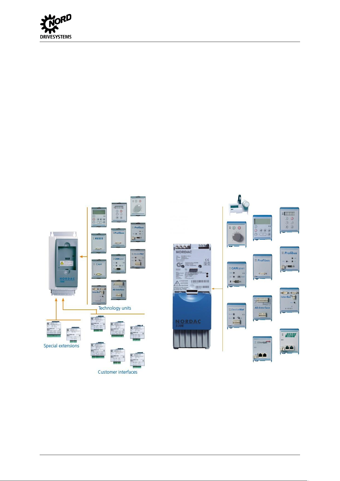
1 Introduction
SK 700E
SK 5xxE
1 Introduction
This document serves for the migration of drive solutions with SK 700E series frequency inverters to
the new model SK 500E. As well as the comparison and migration of the usual modules in the first
part of the document, the middle part deals with the comparison of the connection terminals and the
final part describes the dimensions of the devices.
Both series (SK 700E and SK 500E) are similar in their basic structure, however the performance and
scope of functions of the new series has been considerably increased. Until the end of 2013, the
SK 5xxE will also be available up to size 11 (160.0 kW) for the identical power range of the SK 700E.
The comparison only covers the 3 ph ~ 400 / 480 V types of frequency inverters. The present
document only describes the functions and solutions which could also be implemented with the
SK 700E. In addition, in the description of possible options, only the most common have been
described and listed in detail. The Migration Guide MI 0700 also compares the respective additional
components.
Figure 1: System Overview
Pos: 14 /---------- Seitenumbruch ---------- @ 1\mod_1329145698658_0.docx @ 1589 1 @ @ 1
MI 0700 GB-0414 9
Page 10

Frequency inverters – Migration Guide SK 700E to SK 5xxE
SK 700E
SK 700E
components /
Functions
SK 5xxE
Name
Figure
Figure
Name
SK 700E-xxx-340-A / -O
Frequency inverter
with/without
integrated mains
filter
SK 5xxE-xxx-340-A
SK 700E-xxx-340-A-RS2
Frequency inverter
with integrated
RS232
SK 5xxE-xxx-340-A
incl.
SK TU1-RS2
Technology unit
RS232 interface
SK 5xxE-xxx-340-A
incl.
SK TU1-POT
Technology unit
RS232 interface
SK TU3-POT
SK TU1-xxx
Technology unit
Field bus
SK TU3-xxx
SK TU1-PAR
Technology unit
Parameterbox
SK TU3-PAR
SK TU1-CTR
Technology unit
ControlBox
SK TU3-CTR
SK CU1-xxx
I/O customer units
SK 5xxE-xxx-xxx-A
incl.
SK CU1-xxx
Field bus customer
units
SK 511E-xxx-xxx-A
SK 515E-xxx-xxx-A
on board to integrate
Pos: 15 /Migrationsleitfaden/SK 700E - S K 500E/1. Einleitung/1.1 Komponente nüberblick @ 2\mod_1359636714454_3 88.docx @ 54881 @ 2 @ 1
1.1 Components overview
The following table lists and compares the individual components for the conversion of the two
different frequency inverter series. Both frequency inverter types comply with protection class IP20.
Special variants such as frequency inverters and options with coated boards are not described in
detail.
10 MI 0700 GB-0414
Page 11

1 Introduction
SK 700E
SK 700E
components /
Functions
SK 5xxE
Name
Figure
Figure
Name
SK XU1-ENC
Extension unit
incremental encoder
interface ENCODER
SK 520E-xxx-xxx-A
SK 535E-xxx-xxx-A
incl.
SK XU1-POS
Extension unit
POSICON
SK 530E-xxx-xxx-A
SK 535E-xxx-xxx-A
incl.
SK XU1-POS
+ SSI absolute encoder
Extension unit
POSICON + SSI
absolute encoder
SK 540E-xxx-xxx-A
SK 545E-xxx-xxx-A
incl.
SK BR2-xxx/xxxx-C
Chassis brake
chopper
SK BR2-xxx/xxxx-C
SK BR1-xxx/xxx-F
Footprint resistor
SK BR4-xxx/xxx
HLD 1xx-500/xxx
SK LF1-460/xx-F
Mains filter
several variants
SK HLD 110-500/xxx
SK LF2-480/xxx-F
SK NHD-480/xxx-F
SK CI1-460/xxx-C
Input chokes
SK CI1-480/xxx-C
SK CO1-460/xxx-C
Output chokes
SK CO1-4x0/xxx-C
Table 2: Components overview
Pos: 16 /Migrationsleitfaden/SK 700E - S K 500E/1. Einleitung/1.2 Frequenzu mrichterüberblick @ 2\mod_1359638080 732_388.docx @ 54911 @ 2 @ 1
MI 0700 GB-0414 11
Page 12

Frequency inverters – Migration Guide SK 700E to SK 5xxE
SK 700E
Performance levels
SK 5xxE
Name
Name
SK 700E-xxx-340-X (-RS2) *
optional with integrated
RS232
1.5 kW … 7.5 kW / 2 hp … 10 hp
SK 500E-xxx-340-A
11.0 kW … 160.0 KW / 15 hp … 220 hp
SK 515E-xxx-340-A
SK 700E-xxx-340-X (-RS2) *
+ ENCODER
SK XU1-ENC
1.5 kW … 7.5 kW / 2 hp … 10 hp
SK 520E-xxx-340-A
11.0 kW … 160.0 KW / 15 hp … 220 hp
SK 535E-xxx-340-A
SK 700E-xxx-340-X (-RS2) *
+ POSICON
SK XU1-POS
1.5 kW … 7.5 kW / 2 hp … 10 hp
SK 530E-xxx-340-A
11.0 kW … 160.0 KW / 15 hp … 220 hp
SK 535E-xxx-340-A
SK 700E-xxx-340-X (-RS2) *
+ POSICON
SK XU1-POS
± SSI absolute encoder
+ IO customer unit
SK CU1-xxx **
1.5 kW … 7.5 kW / 2 hp … 10 hp
SK 540E-xxx-340-A
optional
SK EBIOE-2 ***
11.0 kW … 160.0 KW / 15 hp … 220 hp
SK 545E-xxx-340-A
optional
SK EBIOE-2 ***
SK 700E-xxx-340-X (-RS2) *
+ CAN Bus
SK CU1-CAN
1.5 kW … 7.5 kW / 2 hp … 10 hp
SK 511E-xxx-340-A
optional
WAGO adapter module
RJ45/terminal ****
11.0 kW … 160.0 KW / 15 hp … 220 hp
SK 515E-xxx-340-A
optional
WAGO adapter module
RJ45/terminal ****
1.2 frequency inverters overview
The assignment of the SK 700E frequency inverters dependent on function and rated power of the
devices is summarised below. The overview table below shows each of the customer units SK CU1xxx, extension units SK XU1-xxx and the two CAN or CANopen technology options SK TU1-CAN and
SK TU1-CAO for the SK 700E frequency inverter.
Additional functions of field bus systems or technology units (such as AS-Interface, PROFIBUS DP,
DeviceNet etc.) are listed in chapter 2.2.2 Field bus and communication technology units. The I/O
customer unit types SK CU1-xxx of the SK 700E series of frequency inverters are also described there
in greater detail.
Where needed, these different customer units are used to connect I/O control signals.
12 MI 0700 GB-0414
Page 13

1 Introduction
SK 700E
Performance levels
SK 5xxE
Name
Name
SK 700E-xxx-340-X (-RS2) *
+ CAN Bus
SK CU1-CAN-RJ
1.5 kW … 7.5 kW / 2 hp … 10 hp
SK 511E-xxx-340-A
11.0 kW … 160.0 KW / 15 hp … 220 hp
SK 515E-xxx-340-A
SK 700E-xxx-340-X (-RS2) *
+ CAN Bus
SK TU1-CAN
1.5 kW … 7.5 kW / 2 hp … 10 hp
SK 511E-xxx-340-A
optional
WAGO adapter module
RJ45/terminal ****
11.0 kW … 160.0 KW / 15 hp … 220 hp
SK 515E-xxx-340-A
optional
WAGO adapter module
RJ45/terminal ****
SK 700E-xxx-340-X (-RS2) *
+ CANopen Bus
SK TU1-CAO
1.5 kW … 7.5 kW / 2 hp … 10 hp
SK 511E-xxx-340-A
+ CANopen Bus
SK TU3-CAO
11.0 kW … 160.0 KW / 15 hp … 220 hp
SK 515E-xxx-340-A
+ CANopen Bus
SK TU3-CAO
*
(-RS2) with additional optional/integrated RS232 interface on SK 700E frequency inverters ≤ 22.0 kW.
The token X represents A (with integrated mains filter) on SK 700E frequency inverters ≤ 22.0 kW
O (without integrated mains filter) on SK 700E frequency inverters ≥ 30.0 kW
**
plus one of the customer units SK CU1-BSC, SK CU1-STD, SK CU1-MLT or SK CU1-MLT-20mA.
***
When a great number of control signals (number of used DIs and DOs of customer units SK CU1-xxx and extension
units SK XU1-POS) for the SK 700E and the available DIs and DAs of the SK 5xxE are used, an additional IO
extension type SK EBIOE-2 (275900210) is necessary. The IO extension Scan only be connected to SK 540E and
SK 545E frequency inverters.
****
WAGO adapter module RJ45/terminal (278910300) to connect the CAN cable with an RJ45 western plug to the
SK 5xxE, alternatively crimp an RJ45 plug to the CAN cable.
Information
Integrated mains filter
The SK 700E frequency inverters of power range 1.5 kW to 22.0 kW listed above come with an integrated mains
filter of class A by default and are identified with abbreviation -A in the type code. SK 700E frequency inverters
with a power ≥30.0 kW do not feature an integrated mains filter and are identified with abbreviation -O in the type
code. All SK 5xxE frequency inverters (complete power range from 1.5 kW to 160 kW) come ex factory with an
integrated Class C2 (industrial) mains filter. With motor cable lengths ≤ 5 m, the SK 5xxE frequency inverters in
the power range 1.5 kW to 7.5 kW even comply with Class C1 (residential and industrial). All SK 5xxE frequency
inverters feature an on board integrated mains filter and are identified with abbreviation -A in the type code.
For information on the mains filter functions of SK 700E- …-A or … -O frequency inverters with and without
integrated mains filter, please refer to the respective manual (BU 0700) (www.nord.com).
Table 3: Overview of frequency inverter functions
MI 0700 GB-0414 13
Page 14

Frequency inverters – Migration Guide SK 700E to SK 5xxE
Information
RS232 interface variants
The functions of SK 700E frequency inverters in the power range of 1.5 kW to 22.0 kW can also comprise an
additional RS232 interface. Frequency inverter variants with optional RS232 are identified with abbreviation RS2
in the type code on the type label of SK 700E devices. For the power range of 1.5 kW to 22.0 kW, the RS232
interface variant of the SK 700E is an additional optional function. By default, SK 700E frequency inverters
≥ 30.0 kW come with an RS232 / RJ12 interface led out.
For information on the SK 700E- …-A-RS2 frequency inverters with optional RS232 / RJ12 interface, please refer
to the respective manual (BU 0700) (www.nord.com).
RS232 / RJ12 onboard sizes 1 – 4 (optional)
RS232 / RJ12 onboard sizes 5 – 8 (Standard)
Figure 2: optional and on board RS232 / RJ12 interface with SK 700E
Pos: 17 /Migrationsleitfaden/SK 700E - S K 500E/2. Umsetzung/2. Migration @ 2\mod_1357218965236_388.docx @ 5 2836 @ 15 @ 1
14 MI 0700 GB-0414
Page 15

2 Implementation
Sizes 1 – 4 or performance levels ≤ 22.0 kW with
shield bracket for fitting shield clamps
Sizes ≥ 5 or ≥ performance levels 30.0 kW with shield
plate and shield clamps (KGM variant only)
Shield bracket for mounting shield clamps
EMC kit SK EMC 2-x
Information
EMC kits SK EMC2-x
Chapter 2.5 provides an overview of SK EMC 2-x EMC kit available for the SK 5xxE frequency inverter
series specific to size.
Shield bracket
Shield clamp
Shield bracket
PE cable
PE cable
2 Implementation
Frequency inverters of the SK 5xxE series come in 10 different performance levels (SK 500E,
SK 505E, SK 510E, SK 511E, SK 515E, SK 520E, SK 530E, SK 535E, SK 540E, SK 545E). In
general, a distinction is made between SK 5x0E and SK 5x5E devices.
Sizes 1 to 4 of the SK 700E frequency inverters (1.5 kW to 22.0 kW) always come with a shield
bracket fitted to the frequency inverter housing. Shield clamps (size 8 to 35) specific to the cable cross
section and size are not supplied ex factory and, if necessary, will be provided and/or mounted by
persons charged with installation while fitting and setting up the SK 700E frequency inverters.
When migrating an application to the SK 5xxE series of frequency inverters you should always
provide for an additional EMC kit suitable for type SK EMC 2-x according to the size.
SK 700E types
Figure 3: SK 700E: different types (with shield bracket or shield plate)
Figure 4: SK 5xxE size-dependent EMC kits (with shield bracket, shield clamps, PE cable)
Pos: 18 /Migrationsleitfaden/SK 700E - S K 500E/2. Umsetzung/2.1 Frequenzu mrichter @ 2\mod_1357222532792_388. docx @ 52894 @ 2 @ 1
MI 0700 GB-0414 15
Page 16

Frequency inverters – Migration Guide SK 700E to SK 5xxE
SK 700E
SK 700E
Features /
Performance range
SK 5xxE
Name
Name
SK 700E-xxx-340-X (-RS2) *
Standard
Performance 1.5 kW to 7.5 kW
+ incl. mains filter *
+ optional with int. RS232 interface *
SK 500E-xxx-340-A
incl. mains filter Class C2 **
+ RS232 interface
Standard
Performance 11.0 kW to 160.0 kW
+ with/without mains filter *
+ optional / with int. RS232 interface *
SK 515E-xxx-340-A
with mains filter Class C2 **
+ RS232 interface
SK 700E-xxx-340-X (-RS2) *
+ ENCODER
SK XU1-ENC
Standard
Performance 1.5 kW to 7.5 kW
+ incl. mains filter *
+ optional with int. RS232 interface *
+ 1 TTL input for incremental encoder
+ 1 digital input
SK 520E-xxx-340-A
with mains filter Class C2 **
+ RS232 interface
Standard
Performance 11.0 kW to 160.0 kW
+ with/without mains filter *
+ optional / with int. RS232 interface *
+ 1 TTL input for incremental encoder
+ 1 digital input
SK 535E-xxx-340-A
with mains filter Class C2 **
+ RS232 interface
*
(-RS2) with additional optional/integrated RS232 interface on SK 700E frequency inverters ≤ 22.0 kW.
The token X represents A (with integrated mains filter) on SK 700E frequency inverters ≤ 22.0 kW
O (without integrated mains filter) on SK 700E frequency inverters ≥ 30.0 kW
**
The cable lengths must be taken into account because the mains filter characteristics can vary.
NOTICE
Encoder supply voltage
Incremental encoders with 5 V supply voltage can be directly operated with frequency inverters of the SK 700E
series. For the SK 5xxE series of frequency inverters, the connected incremental encoders must be suitable for a
supply voltage range of 10 V … 30 V.
This is why the incremental encoders must be replaced or the "old" encoders must be supplied from an external
power supply when migrating to SK 5xxE frequency inverters.
2.1 Frequency inverter
Pos: 19 /Migrationsleitfaden/SK 700E - S K 500E/2. Umsetzung/2.1.1. Performan ce-Stufen @ 2\mod_1357222355717 _388.docx @ 52870 @ 3 @ 1
2.1.1 Performance levels
Table 4: Overview SK 5xxE standard and incremental encoder input
16 MI 0700 GB-0414
Page 17

2 Implementation
SK 700E
SK 700E
Features /
Performance range
SK 5xxE
Name
Name
SK 700E-xxx-340-X (-RS2) *
+ CAN Bus
SK CU1-CAN
Standard
Performance 1.5 kW to 7.5 kW
+ incl. mains filter *
+ optional with int. RS232 interface *
+ 1 digital input
+ 1 relay contact
+ CAN connecti0on via terminals
alternatively with RJ45 socket
SK 511E-xxx-340-A
with mains filter Class C2 **
+ RS232 interface
optional
WAGO
adapter module
RJ45/terminal ***
Standard
Performance 11.0 kW to 160.0 kW
+ with/without mains filter *
+ optional / with int. RS232 interface *
+ 1 digital input
+ 1 relay contact
+ CAN connecti0on via terminals
alternatively with RJ45 socket
SK 515E-xxx-340-A
with mains filter Class C2 **
+ RS232 interface
optional
WAGO
adapter module
RJ45/terminal ***
SK 700E-xxx-340-X (-RS2) *
+ CAN Bus
SK CU1-CAN-RJ
Standard
Performance 1.5 kW to 7.5 kW
+ incl. mains filter *
+ optional with int. RS232 interface *
+ 5 digital inputs
+ 1 relay contact
+ CAN connection with 2 x RJ45 socket
SK 511E-xxx-340-A
with mains filter Class C2 **
+ RS232 interface
Standard
Performance 11.0 kW to 160.0 kW
+ with/without mains filter *
+ optional / with int. RS232 interface *
+ 5 digital inputs
+ 1 relay contact
+ CAN connection with 2 x RJ45 socket
SK 515E-xxx-340-A
with mains filter Class C2 **
+ RS232 interface
SK 700E-xxx-340-X (-RS2) *
+ CAN Bus
SK TU1-CAN
Standard
Performance 1.5 kW to 7.5 kW
+ incl. mains filter *
+ optional with int. RS232 interface *
+ CAN connection sub-D9 socket
SK 511E-xxx-340-A
with mains filter Class C2 **
+ RS232 interface
optional
WAGO
adapter module
RJ45/terminal ***
Standard
Performance 11.0 kW to 160.0 kW
+ with/without mains filter *
+ optional / with int. RS232 interface *
+ CAN connection via 9-pole sub-D
socket
SK 515E-xxx-340-A
with mains filter Class C2 **
+ RS232 interface
optional
WAGO
adapter module
RJ45/terminal ***
MI 0700 GB-0414 17
Page 18

Frequency inverters – Migration Guide SK 700E to SK 5xxE
SK 700E
SK 700E
Features /
Performance range
SK 5xxE
Name
Name
SK 700E-xxx-340- X (-RS2) *
+ CANopen Bus
SK TU1-CAO
Standard
Performance 1.5 kW to 7.5 kW
+ incl. mains filter *
+ optional with int. RS232 interface *
+ CAN connection via 9-pole sub-D
socket
+ Connection of external 24 V supply
voltage
+ CANopen addressing with rotary coding
switch
+ Baud rate adjustment with rotary coding
switch
+ DIP switch termination resistor
SK 500E-xxx-340-A
incl. mains filter Class C2 **
+ RS232 interface
+ CANopen Bus
SK TU3-CAO
Standard
Performance 11.0 kW to 160.0 kW
+ with/without mains filter *
+ optional / with int. RS232 interface *
+ CAN connection via 9-pole sub-D
socket
+ Connection of external 24 V supply
voltage
+ CANopen addressing with rotary coding
switch
+ Baud rate adjustment with rotary coding
switch
+ DIP switch termination resistor
SK 515E-xxx-340-A
with mains filter Class C2 **
+ RS232 interface
+ CANopen Bus
SK TU3-CAO
*
(-RS2) with additional optional/integrated RS232 interface on SK 700E frequency inverters ≤ 22.0 kW.
The token X represents A (with integrated mains filter) on SK 700E frequency inverters ≤ 22.0 kW
O (without integrated mains filter) on SK 700E frequency inverters ≥ 30.0 kW
**
The cable lengths must be taken into account because the mains filter characteristics can vary.
***
RJ45 WAGO adapter module (278910300) to connect the CAN cable with an RJ45 western plug to the SK 5xxE,
alternatively crimp an RJ45 plug to the CAN cable.
Table 5: Overview of SK 5xxE performance levels for CAN and CANopen
18 MI 0700 GB-0414
Page 19
2 Implementation
SK 700E
SK 700E
Features /
Performance range
SK 5xxE
Name
Name
SK 700E-xxx-340- A (-RS2) *
+ POSICON
SK XU1-POS
+ with or without
SSI absolute encoder
Standard
Performance 1.5 kW to 7.5 kW
+ incl. mains filter *
+ optional with int. RS232 interface *
+ 6 digital inputs
+ 1 multifunction relay
+ POSICON positioning control
+ 1 TTL input for incremental encoder
+ 1 SSI absolute encoder input
SK 530E-xxx-340-A
with mains filter Class C2 **
+ RS232 interface
+ without SSI absolute encoder
connection
SK 540E-xxx-340-A
with mains filter Class C2 **
+ RS232 interface
+ with universal encoder-
interface, e.g. for SSI absolute
encoder connection
Standard
Performance 11.0 kW to 22.0 kW
+ incl. mains filter *
+ optional with int. RS232 interface *
+ 6 digital inputs
+ 1 multifunction relay
+ POSICON positioning control
+ 1 TTL input for incremental encoder
+ 1 SSI absolute encoder input
SK 535E-xxx-340-A
with mains filter Class C2 **
+ RS232 interface
+ without SSI absolute encoder
connection
SK 700E-xxx-340-O
+ POSICON
SK XU1-POS
+ with or without
SSI absolute encoder
Standard
Performance 30.0 kW to 160.0 kW
+ without mains filter *
+ integrated RS232 interface *
+ 6 digital inputs
+ 1 multifunction relay
+ POSICON positioning control
+ 1 TTL input for incremental encoder
+ 1 SSI absolute encoder input
SK 545E-xxx-340-A
with mains filter Class C2 **
+ RS232 interface
+ with universal encoder-
interface, e.g. for SSI absolute
encoder connection
MI 0700 GB-0414 19
Page 20

Frequency inverters – Migration Guide SK 700E to SK 5xxE
SK 700E
SK 700E
Features /
Performance range
SK 5xxE
Name
Name
see previous page
+ plus
IO customer unit
SK CU1-xxx ****
Standard
Performance 1.5 kW to 7.5 kW
+ incl. mains filter *
+ optional with int. RS232 interface *
plus I/O control connections of the
respective SK CU1-xxx customer unit
SK 540E-xxx-340-A
with mains filter Class C2 **
+ RS232 interface
optional
IO extension
SK EBIOE-2 *****
Standard
Performance 11.0 kW to 22.0 kW
+ incl. mains filter *
+ optional with int. RS232 interface *
plus I/O control connections of the
respective SK CU1-xxx customer unit
SK 545E-xxx-340-A
with mains filter Class C2 **
+ RS232 interface
optional
IO extension
SK EBIOE-2 *****
Standard
Performance 30.0 kW to 160.0 kW
+ without mains filter *
+ integrated RS232 interface *
plus I/O control connections of the
respective SK CU1-xxx customer unit
*
(-RS2) with additional optional/integrated RS232 interface on SK 700E frequency inverters ≤ 22.0 kW.
The token X represents A (with integrated mains filter) on SK 700E frequency inverters ≤ 22.0 kW
O (without integrated mains filter) on SK 700E frequency inverters ≥ 30.0 kW
**
The cable lengths must be taken into account because the mains filter characteristics can vary.
****
Plus one of the following IO customer units:
SK CU1-BSC, SK CU1-STD, SK CU1-MLT or SK CU1-MLT-20mA.
*****
When using a great number of digital control signals (number of used (from SK 700E + option) and available (SK
5xxE) digital inputs. The IO extension SK EBIOE-2 (275900210) can only be connected to SK 540E and SK 545E
frequency inverters.
NOTICE
Encoder supply voltage
Incremental encoders with 5 V supply voltage can be directly operated with frequency inverters of the SK 700E
series. For the SK 5xxE series of frequency inverters, the connected incremental encoders must be suitable for a
supply voltage range of 10 V … 30 V.
This is why the incremental encoders must be replaced or the "old" encoders must be supplied from an external
power supply when migrating to SK 5xxE frequency inverters.
Table 6: Overview of SK 5xxE performance levels for POSICON positioning control
Pos: 20 /---------- Seitenumbruch ---------- @ 1\mod_1329145698658_0.docx @ 1589 1 @ @ 1
20 MI 0700 GB-0414
Page 21

2 Implementation
Information
CAN / CANopen 24 V supply
When using the onboard CAN / CANopen interface of ≥ SK 511E frequency inverters, it is mandatory to connect
an additional 24 V power supply for the CAN / CANopen Bus to the RJ45 sockets.
For easier cabling and connection of functions (for 24 V supply and CAN / CANopen bus connection cables), the
WAGO adapter module RJ45/terminal (see chapter 2.1.3 Additional options for the functions) can be used with
conventional patch cables.
Customer unit
SK CU1-xxx
Part number
SK 700E
IO customer unit
data
Frequency inverter
SK 5xxE +
additional options
Frequency inverter
SK 54xE + / or
additional options
Basic IO
SK CU1-BSC
278200000
Basic customer unit
1 x multifunction relay
3 x digital inputs
1 x analogue input 0…10 V
all SK 5xxE *
onboard
Standard IO
SK CU1-STD
278200020
Standard customer unit
2 x multifunction relays
4 x digital inputs
1 x analogue input 0…10 V,
0/4…20 mA
1 x analogue output, 0…10 V
1 x RS485 interface
all SK 5xxE *
onboard
*
All frequency inverters, except SK 515E (available ≥ size 5 only).
Pos: 21 /Migrationsleitfaden/SK 700E - S K 500E/2. Umsetzung/2.1.2 Kundensc hnittstellen und Sondererweiterungen @ 2\mod_1357225777503_388.doc x @ 52918 @ 3 @ 1
2.1.2 Customer units and extension units
To connect I/O control signals to the SK 700E frequency inverters, additional SK CU1-xxx IO
customer units are required. In contrast, the SK 5xxE series of frequency inverters by default comes
with respective onboard terminals to connect the standard I/O control signals.
When migrating to an SK 500E frequency inverter, you should provide for a performance level ≥
SK 511E with integrated onboard CAN / CANopen interface for SK 700E field bus customer units of
SK CU1-CAN and SK CU1-CAN-RJ types.
For the SK 5xxE series of frequency inverters, only one of the two PROFIBUS DP technology units
type SK TU3-PBR or …-24V can be planned in connection with a SK 700E PROFIBUS DP field bus
customer unit type SK CU1-PBR.
Special extensions ENCODER / incremental encoder input type SK XU1-ENC and the POSICON
positioning control SK XU1-POS of the SK 700E frequency inverter are migrated to the SK 5xxE
series of frequency inverters with different performance levels such as the SK 52xE (with ENCODER /
incremental encoder input) or the SK 53xE (with POSICON / positioning control) series.
The sub-chapters to follow list some differences in function of the two series of frequency inverters
that must be heeded under all circumstances which must be taken into account when migrating from
the SK 700E to the SK 5xxE series or when migrating applications:
MI 0700 GB-0414 21
Page 22

Frequency inverters – Migration Guide SK 700E to SK 5xxE
Customer unit
SK CU1-xxx
Part number
SK 700E
IO customer unit
data
Frequency inverter
SK 5xxE +
additional options
Frequency inverter
SK 54xE + / or
additional options
Multi IO
SK CU1-MLT
278200010
Multi customer unit
2 x multifunction relays
6 x digital inputs
2 x analogue inputs -10…+10 V,
0/4…20 mA
2 x analogue outputs, 0…10 V
1.5 kW…7.5 kW
SK 520E, SK 530E,
SK 535E onboard
only 1st analogue output,
0…10 V
SK 540E, SK 545E
onboard
only 1st analogue
output, 0…10 V
optional
setpoint converter ±10 V **
for analogue inputs
IO extension
SK EBIOE-2 ***
for 2nd analogue output,
0…10 V
11.0 kW…160.0 kW
SK 535E
onboard
1st analogue output only,
0…10 V
SK 545E
onboard
1st analogue output
only, 0…10 V
IO extension
SK EBIOE-2 ***
for 2nd analogue output,
0…10 V
Multi IO
SK CU1-MLT-20mA
278200015
Customer unit Multi 20mA
analogue outputs
2 x multifunction relays
6 x digital inputs
2 x analogue inputs -10…+10 V,
0/4…20 mA
2 x analogue outputs, 0…20 mA
1.5 kW…7.5 kW
SK 520E, SK 530E,
SK 535E onboard
only 1st analogue output,
0…10 V
SK 540E, SK 545E
onboard
only 1st analogue
output, 0…10 V
optional
setpoint converter ±10 V **
for analogue inputs
IO extension
SK EBIOE-2 ***
for 2nd analogue output,
0…10 V
optional external signal converter ****
for 1st analogue output,, 0/4…20 mA
11.0 kW…160.0 kW
SK 535E
onboard
1st analogue output only,
0…10 V
SK 545E
onboard
1st analogue output only,
0…10 V
IO extension
SK EBIOE-2 ***
for 2nd analogue output,
0…10 V
optional external signal converter ****
for 1st analogue output,, 0/4…20 mA
**
The setpoint converter ±10 V (278910320) is only needed for sizes 1 to 4 (1.5 kW to 7.5 kW) of all SK 5xxE
frequency inverters.
***
The IO extension SK EBIOE-2 (275900210) can be used to connect the 2nd analogue output (0…10 V) and the two
analogue inputs (-10 V…+10 V). Thus, additional ±10 V setpoint converters (278910320) are not needed.
****
The analogue 0…10 V output signal of SK 5xxE frequency inverters must be converted to 0/4…20 mA with a
commercially external signal converter.
Table 7: Overview and assignment of SK 700E IO customer units SK CU1-xxx
22 MI 0700 GB-0414
Page 23

2 Implementation
Customer unit
SK CU1-xxx
Part number
SK 700E
Field bus customer unit
data
Frequency inverter SK 5xxE +
Additional options
Part number
PROFIBUS DP
SK CU1-PBR
278200030
PROFIBUS DP customer unit
1 x multifunction relay
1 x digital input
1 x PROFIBUS DP *****
all SK 5xxE *
onboard
+ plus technology option
PROFIBUS DP
SK TU3-PBR *****
275900030
CAN Bus
SK CU1-CAN
278200050
CAN customer unit
1 x multifunction relay
5 x digital inputs
2 x CAN bus
all ≥ SK 511E *
onboard
optional WAGO
RJ45 adapter module/terminal ******
278910300
CAN Bus
SK CU1-CAN-RJ
278200052
CAN customer unit
with RJ45 sockets
1 x multifunction relay
5 x digital inputs
2 x RJ45 CAN bus sockets
all ≥ SK 511E *
onboard
optional WAGO
RJ45 adapter module/terminal ******
278910300
USS bus
USS Customer Interface
1 x multifunction relay
1 x digital input
1 x RS485 interface *******
all SK 5xxE *
onboard
SK CU1-USS
278200040
*
All frequency inverters, except SK 515E (available ≥ size 5 only).
*****
If next to the PROFIBUS DP customer unit SK CU1-PBR an operation and diagnostic technology unit is also used
with the SK 700E application, a SimpleBox SK CSX-0 or a handheld control box SK PAR-3H or SK CSX-3H should
be planned for SK 5xxE application, in addition to the technology unit SK TU3-PBR for frequency inverter operation.
The connection types of the two different PROFIBUS DP field bus options also differ. PROFIBUS DP connection to
the SK CU1-PBR customer unit occurs via spring loaded terminals. PROFIBUS DP connection to the technology unit
SK TU3-PBR or SK TU3-PBR-24V occurs at the front with a 9-pole SUB-D connector (must be provided separately).
For more information refer to the PROFIBUS DP Supplementary Operating Instructions BU 0020 (see
www.nord.com).
******
The WAGO adapter module RJ45 / terminal (278910300) and commercially available pre-assembled RJ45 patch
cables allow for easy connection of the additional external 24 V power supply for the CAN bus and the CAN
connection cables.
*******
All frequency inverters ≥ SK 520E feature the RS485 interface next to the RJ12 on connector block X11 and also on
terminal block X7 or terminals 74 and 75.
Table 8: Overview and assignment of field bus customer units SK CU1-xxx
MI 0700 GB-0414 23
Page 24

Frequency inverters – Migration Guide SK 700E to SK 5xxE
Customer unit
SK XU1-xxx
Part number
SK 700E
Extension unit
Data
Frequency inverter SK 5xxE +
additional options
Incremental encoder-
input / ENCODER
SK XU1-ENC
278200120
ENCODER
1 x digital input
1 x incremental encoder input
TTL, RS422
5 / 15 V power supply for
rotary encoder
all ≥ SK 520E
onboard
optional external 5 V
power supply for rotary encoder
Positioning /
POSICON
SK XU1-POS
278200130
POSICON
6 x digital input
2 x multi-function relays
1 x incremental encoder input
TTL, RS422
5 / 15 V power supply for
rotary encoder
1 x SSI absolute encoder input
5 / 15 V power supply for
rotary encoder
all ≥ SK 530E
onboard
optional external 5 V
power supply for rotary encoder
NOTICE
Encoder supply voltage
Rotary encoder with 5 V power supply must not be connected to the SK 5xxE frequency inverters directly. For
this application, a commercially external power supply should be used because the SK 5xxE frequency inverters
only feature a 10…30 V output for connection of a incremental encoder.
This is why the rotary encoders must be replaced or the "old" encoders must be supplied from an external 5 V
power supply when migrating to SK 5xxE frequency inverters.
Table 9: Overview and assignment of extension units SK XU1-xxx
Pos: 22 /---------- Seitenumbruch ---------- @ 1\mod_1329145698658_0.docx @ 1589 1 @ @ 1
24 MI 0700 GB-0414
Page 25

2 Implementation
Options
Name
Picture
Part Number
WAGO
adapter module
RJ45/terminal
278910300
Setpoint converter
±10 V → 0 … 10 V
278910320
IO extension
SK EBIOE-2
(only SK 540E / SK 545E)
275900210
Information
WAGO adapter module RJ45/terminal
The WAGO adapter module RJ45/terminal comes with a shield clamp and is used to connect the CAN bus cable
sand the external necessary 24 V power supply for the CAN / CANopen bus system. Signal connection occurs
with spring terminals on the input side and an RJ45 western socket on the output side. This adapter module
RJ45/terminal facilitates the connection of the CAN bus system to frequency inverters of performance levels ≥
SK 52xE.
For more information and details, please refer to the operating instructions of the frequency inverter.
Information
Setpoint converter ± 10 V
The setpoint converter ± 10 V is used to convert the signal for the analogue inputs of unipolar (0 … 10 V and
0 / 4 … 20 mA) to bipolar (- 10 V … + 10 V) voltages. SK 5xxE frequency inverters of size 5 (≥ 11 kW) and higher
can process unipolar and also bipolar analogue inputs by way of configuration with DIP switches.
For more information and details, please refer to the operating instructions of the frequency inverter.
Information
IO extension
IO extension SK EBIOE-2 lets you connect additional IO control signals and is suitable for SK 540E or SK 545E
frequency inverters.
For more details please refer to Technical Information / Data Sheet TI 275900210.
Pos: 23 /Migrationsleitfaden/SK 700E - S K 500E/2. Umsetzung/2.1.3 Zusätzlic he Optionen für die Funktionalitäten @ 2\ mod_1358177217573_388.docx @ 53251 @ 3 @ 1
2.1.3 Additional options for the functions
To migrate the various application functions, several options are available for the SK 5xxE series of
frequency inverters.
Table 10: Overview of additional function options
Pos: 24 /Migrationsleitfaden/SK 700E - S K 500E/2. Umsetzung/2.1.4 Leistungsst ufen SK 700E Baugrößen 1 + 2 / 1,5 kW - 7,5 kW @ 2\mod_1360071744 165_388.docx @ 55065 @ 3 @ 1
MI 0700 GB-0414 25
Page 26
Frequency inverters – Migration Guide SK 700E to SK 5xxE
Type: SK 700E-151-340-A (-RS2)
Part No.: 278100150 / …(152)
Type: SK 700E-221-340-A (-RS2)
Part No.: 278100220 / …(222)
Type: SK 700E-301-340-A (-RS2)
Part No.: 278100300 / …(302)
Type: SK 700E-401-340-A (-RS2)
Part No.: 278100400 / …(402)
Type: SK 700E-551-340-A (-RS2)
Part No.: 278100550 / …(552)
Type: SK 700E-751-340-A (-RS2)
Part No.: 278100750 / …(752)
Customer unit
without extension
unit
with extension unit
SK XU1-xxx
SK CU1-xxx
Encoder
SK XU1-ENC
278200120
POSICON
SK XU1-POS
278200130
Basic IO
SK CU1-BSC
278200000
SK 500E-151-340-A
275420150
SK 520E-151-340-A
275520150
SK 540E-151-340-A
275620160
+ optional *
IO extension
SK EBIOE-2
275900210
SK 500E-221-340-A
275420220
SK 520E-221-340-A
275520220
SK 540E-221-340-A
275620230
SK 500E-301-340-A
275420300
SK 520E-301-340-A
275520300
SK 540E-301-340-A
275620310
Standard IO
SK CU1-STD
278200020
SK 500E-401-340-A
275420400
SK 520E-401-340-A
275520150
SK 540E-401-340-A
275620410
SK 500E-551-340-A
275420550
SK 520E-551-340-A
275520550
SK 540E-551-340-A
275620560
SK 500E-751-340-A
275420750
SK 520E-751-340-A
275520750
SK 540E-751-340-A
275620760
Number of used
analogue outputs
1 analogue output
2 analogue outputs
Multi IO
SK CU1-MLT
278200010
SK 520E-151-340-A **
275520150
+ optional ***
Setpoint converter
± 10 V
278910320
SK 540E-151-340-A **
275620160
+ optional *
IO extension
SK EBIOE-2
275900210
SK 520E-221-340-A **
275520220
SK 540E-221-340-A **
275620230
SK 520E-301-340-A **
275520300
SK 540E-301-340-A **
275620310
Multi IO
SK CU1-MLT-20mA **
278200015
SK 520E-401-340-A **
275520400
SK 540E-401-340-A **
275620410
SK 520E-551-340-A **
275520550
SK 540E-551-340-A **
275620560
SK 520E-751-340-A **
275520750
SK 540E-751-340-A **
275620760
+ CAN Bus
SK CU1-CAN
278200050
SK 520E-151-340-A
275520150
SK 540E-151-340-A
275620160
SK 520E-221-340-A
275520220
SK 540E-221-340-A
275620230
SK 520E-301-340-A
275520300
SK 540E-301-340-A
275620310
CAN Bus
SK CU1-CAN-RJ
278200052
SK 520E-401-340-A
275520400
SK 540E-401-340-A
275620410
SK 520E-551-340-A
275520550
SK 540E-551-340-A
275620560
SK 520E-751-340-A
275520750
SK 540E-751-340-A
275620760
*
To connect more digital inputs (acc. to SK XU1-POS) to the SK 540E frequency inverter, the optional IO extension
SK EBIOE-2 (275900210) is offered. To connect the analogue inputs ± 10 V to SK 5x0E frequency inverters of sizes 1 - 4,
the setpoint converters ± 10 V → 0 … 10 V (278910320) are offered. As an alternative, the ± 10 V analogue inputs can also
be connected with terminal blocks X1 + X2 (see TI 275900210) when an IO extension of type SK EBIOE-2 (275900210) is
used.
**
Commercially available external signal converters are necessary if the analogue outputs of the SK 5x0E frequency inverters
are used and signal conversion to 0/4 … 20 mA compatible with SK CU1-MLT-20mA is necessary.
***
To connect the analogue inputs ± 10 V to the SK 520E frequency inverters of sizes 1 to 4, the setpoint converters ± 10 V →
0 … 10 V (278910320) are offered.
2.1.4 Performance levels SK 700E sizes 1 + 2 / 1.5 kW to 7.5 kW
Pos: 25 /Migrationsleitfaden/SK 700E - S K 500E/2. Umsetzung/Leistungsstufe n/BG 1 + 2/Leistungsstufen SK 700E B augrößen 1 + 2 / 1,5 kW - 7,5 kW @ 3\ mod_1370859481016_388.docx @ 76 646 @ @ 1
Table 11: Performance levels SK 700E sizes 1 + 2 / 1.5 kW to 7.5 kW
Pos: 26 /Migrationsleitfaden/SK 700E - S K 500E/2. Umsetzung/2.1.5 Leistungsst ufen SK 700E Baugrößen 3 - 5 / 11, 0 kW - 37,0 kW @ 3\mod_1370858876 644_388.docx @ 76596 @ 3 @ 1
26 MI 0700 GB-0414
Page 27

2 Implementation
Type: SK 700E-112-340-A (-RS2)
Part No.: 278101100 / …(102)
Type: SK 700E-152-340-A (-RS2)
Part No.: 278101500 / …(502)
Type: SK 700E-182-340-A (-RS2)
Part No.: 278101850 / …(852)
Type: SK 700E-222-340-A (-RS2)
Part No.: 278102200 / …(202)
Type: SK 700E-302-340-O
Part No.: 278103000
Type: SK 700E-372-340-O
Part No.: 278103700
Customer unit
without extension
unit
with extension unit
SK XU1-xxx
SK CU1-xxx
Encoder
SK XU1-ENC
278200120
POSICON
SK XU1-POS
278200130
Basic IO
SK CU1-BSC
278200000
SK 515E-112-340-A
275721100
SK 535E-112-340-A
275921100
SK 545E-112-340-A
275921110
+ optional *
IO extension
SK EBIOE-2
275900210
SK 515E-152-340-A
275721500
SK 535E-152-340-A
275921500
SK 545E-152-340-A
275921510
SK 515E-182-340-A
275721850
SK 535E-182-340-A
275921850
SK 545E-182-340-A
275921860
Standard IO
SK CU1-STD
278200020
SK 515E-222-340-A
275722200
SK 535E-222-340-A
275922200
SK 545E-222-340-A
275922210
SK 515E-302-340-A
275723000
SK 535E-302-340-A
275923000
SK 545E-302-340-A
275923010
SK 515E-372-340-A
275723700
SK 535E-372-340-A
275923700
SK 545E-372-340-A
275923710
Number of used
analogue outputs
1 analogue output
2 analogue outputs
Multi IO
SK CU1-MLT
278200010
SK 535E-112-340-A **
275921100
SK 545E-112-340-A **
275921110
+ optional *
IO extension
SK EBIOE-2
275900210
SK 545E-152-340-A **
275921510
SK 535E-152-340-A **
275921500
SK 545E-182-340-A **
275921860
Multi IO
SK CU1-MLT-20mA **
278200015
SK 545E-222-340-A **
275922210
SK 535E-182-340-A **
275921850
SK 545E-302-340-A **
275923010
SK 545E-372-340-A **
275923710
+ CAN Bus
SK CU1-CAN
278200050
SK 535E-222-340-A **
275922200
SK 545E-112-340-A
275921110
SK 545E-152-340-A
275921510
SK 535E-302-340-A **
275923000
SK 545E-182-340-A
275921860
CAN Bus
SK CU1-CAN-RJ
278200052
SK 545E-222-340-A
275922210
SK 535E-372-340-A **
275923700
SK 545E-302-340-A
275923010
SK 545E-372-340-A
275923710
*
To connect more digital inputs (acc. to SK XU1-POS) to the SK 545E frequency inverter, the optional IO extension
SK EBIOE-2 (275900210) is offered. Connection of the analogue inputs ± 10 V to the SK 545E frequency inverters occurs
directly to the terminal block X4 of the SK 545E from size 5 onward. As an alternative, the ± 10 V analogue inputs can also
be connected with terminal blocks X1 + X2 (see TI 275900210) when an IO extension of type SK EBIOE-2 (275900210) is
used.
**
Commercially available external signal converters are necessary if the analogue outputs of the SK 5x5E frequency inverters
are used and signal conversion to 0/4 … 20 mA compatible with SK CU1-MLT-20mA is necessary. As an alternative,
connection could occur to terminal block X2 (see TI 275900210) if only one 0/4 … 20 mA analogue output is used in
conjunction with an SK 545E frequency inverter and a type SK EBIOE-2 (275900210) IO extension.
2.1.5 Performance levels SK 700E sizes 3 - 5 / 11.0 kW to 37.0 kW
Pos: 27 /Migrationsleitfaden/SK 700E - S K 500E/2. Umsetzung/Leistungsstufe n/BG 3 - 5/Leistungsstufen SK 700E B augrößen 3 - 5 / 11,0 kW - 37,0 kW @ 3\mod_1371471999028_388.docx @ 78 364 @ @ 1
Table 12: Performance levels SK 700E sizes 3 - 5 / 11.0 kW to 37.0 kW
Pos: 28 /Migrationsleitfaden/SK 700E - S K 500E/2. Umsetzung/2.1.6 Leistungsst ufen SK 700E Baugrößen 6 - 8 / 45, 0 kW - 160,0 kW @ 3\mod_137085910 3683_388.docx @ 76621 @ 3 @ 1
MI 0700 GB-0414 27
Page 28

Frequency inverters – Migration Guide SK 700E to SK 5xxE
Type: SK 700E-452-340-O
Part No.: 278104500
Type: SK 700E-552-340-O
Part No.: 278105500
Type: SK 700E-752-340-O
Part No.: 278107500
Type: SK 700E-902-340-O
Part No.: 278109001
Type: SK 700E-113-340-O
Part No.: 278111000
Type: SK 700E-133-340-O
Part No.: 278103200
Type: SK 700E-163-340-O-VT
Part No.: 278116000
Customer unit
without extension
unit
with extension unit
SK XU1-xxx
SK CU1-xxx
Encoder
SK XU1-ENC
278200120
POSICON
SK XU1-POS
278200130
Basic IO
SK CU1-BSC
278200000
SK 515E-452-340-A
275724500
SK 535E-452-340-A
275924500
SK 545E-452-340-A
275924510
+ optional *
IO extension
SK EBIOE-2
275900210
SK 515E-552-340-A
275725500
SK 535E-552-340-A
275925500
SK 545E-552-340-A
275925510
SK 515E-752-340-A
275727500
SK 535E-752-340-A
275927500
SK 545E-752-340-A
275927510
Standard IO
SK CU1-STD
278200020
SK 515E-902-340-A
275729000
SK 535E-902-340-A
275929000
SK 545E-902-340-A
275929010
SK 515E-113-340-A
275721130
SK 535E-113-340-A
275921130
SK 545E-113-340-A
275921140
SK 515E-133-340-A
275721330
SK 535E-133-340-A
275921330
SK 545E-133-340-A
275921340
SK 515E-163-340-A
275721630
SK 535E-163-340-A
275921630
SK 545E-163-340-A
275921640
Number of used
analogue outputs
1 analogue output
2 analogue outputs
Multi IO
SK CU1-MLT
278200010
SK 535E-452-340-A **
275924500
SK 545E-452-340-A **
275924510
+ optional *
IO extension
SK EBIOE-2
275900210
SK 545E-552-340-A **
275925510
SK 535E-552-340-A **
275925500
SK 545E-752-340-A **
275927510
Multi IO
SK CU1-MLT-20mA **
278200015
SK 545E-902-340-A **
275929010
SK 535E-752-340-A **
275927500
SK 545E-113-340-A **
275921140
SK 545E-133-340-A **
275921340
SK 535E-902-340-A **
275929000
SK 545E-163-340-A
275921640
+ CAN Bus
SK CU1-CAN
278200050
SK 545E-452-340-A
275924510
SK 535E-113-340-A **
275921130
SK 545E-552-340-A
275925510
SK 545E-752-340-A
275927510
CAN Bus
SK CU1-CAN-RJ
278200052
SK 535E-133-340-A **
275921330
SK 545E-902-340-A
275929010
SK 545E-113-340-A
275921140
SK 535E-163-340-A
275921630
SK 545E-133-340-A
275921340
SK 545E-163-340-A
275921640
2.1.6 Performance levels SK 700E sizes 6 - 8 / 45.0 kW to 160.0 kW
Pos: 29 /Migrationsleitfaden/SK 700E - S K 500E/2. Umsetzung/Leistungsstufe n/BG 6 - 8/Leistungsstufen SK 700E B augrößen 6 - 8 / 45,0 kW - 160,0 kW @ 3 \mod_1371556221180_388.docx @ 7 8761 @ @ 1
28 MI 0700 GB-0414
Page 29

2 Implementation
*
To connect more digital inputs (acc. to SK XU1-POS) to the SK 545E frequency inverter, the optional IO extension
SK EBIOE-2 (275900210) is offered. Connection of the analogue inputs ± 10 V to the SK 545E frequency inverters occurs
directly to the terminal block X4 of the SK 545E from size 5 onward.
As an alternative, the ± 10 V analogue inputs can also be connected with terminal blocks X1 + X2 (see TI 275900210) when
an IO extension of type SK EBIOE-2 (275900210) is used.
**
Commercially available external signal converters are necessary if the analogue outputs of the SK 5x5E frequency inverters
are used and signal conversion to 0/4 … 20 mA compatible with SK CU1-MLT-20mA is necessary.
As an alternative, connection could occur to terminal block X2 (see TI 275900210) if only one 0/4 … 20 mA analogue
output is used in conjunction with an SK 545E frequency inverter and a type SK EBIOE-2 (275900210) IO extension.
Table 13: Performance levels SK 700E sizes 6 - 8 / 45.0 kW to 160.0 kW
Pos: 30 /Migrationsleitfaden/SK 700E - S K 500E/2. Umsetzung/2.2 Technologi eboxen @ 3\mod_1361778999600_388. docx @ 59576 @ 2 @ 1
2.2 Technology units
The technology units are available as optional extensions for the modular slot on the front of the
frequency inverter. There are plug-in technology units for communications and operation/diagnosis.
The first sub-chapter presents the optional and replaceable operation/diagnosis options providing data
backup and saving functions (number of storage areas) of parameter and data records.
The second sub-chapter presents the optional and replaceable communication technology units.
These are used for individual solutions and applications for implementing the standard field bus
control systems such as PROFIBUS DP, CAN, CANopen, DeviceNet, AS-Interface, etc.
Pos: 31 /---------- Seitenumbruch ---------- @ 1\mod_1329145698658_0.docx @ 1589 1 @ @ 1
MI 0700 GB-0414 29
Page 30

Frequency inverters – Migration Guide SK 700E to SK 5xxE
Technology unit
SK TU1-xxx
Part No.
Name
Information
Data
Technology unit
SK TU3-xxx
Part No.
SK TU1-POT
278200110
PotentiometerBox
• 1 setpoint potentiometer 0 … 100 %
• ON/OFF button
• Status LEDs
SK TU3-POT
275900110
SK TU1-CTR
278200090
ControlBox
• 4-digit 7-segment LED display
• ON/OFF /Reverse button
• save 1 data record
• display parameter record LEDs
SK TU3-CTR
275900090
SK TU1-PAR
278200100
ParameterBox
• illuminated plain text display
• 4-row LCD
• ON/OFF /Reverse button
• save 5 data records
• Status LEDs
• 6 languages
• help texts
SK TU3-PAR
275900100
SimpleBox
not available
SimpleBox (par. operation with SK TU3-xxx possible)
• 4-digit 7-segment LED display
• ON/OFF Button/rotating knob
• display parameter record LEDs
• connect to diagnosis RJ12 socket of
frequency inverter
SK CSX-0
275900095
Information
Operating Manual
For more information on the technology units for operation and diagnosis listed in this chapter (PotentiometerBox,
ControlBox, ParameterBox and SimpleBox), refer to the separate Operating Instructions BU 0040 (see
www.nord.com).
Pos: 32 /Migrationsleitfaden/SK 700E - S K 500E/2. Umsetzung/2.2.1 Bedienung- und Diagnose- Technologieboxen @ 3\mod_1361807799118_388.docx @ 59951 @ 3 @ 1
2.2.1 Technology units for operation and diagnosis
Table 14: Technology units for operation and diagnosis
Pos: 33 /---------- Seitenumbruch ---------- @ 1\mod_1329145698658_0.docx @ 1589 1 @ @ 1
30 MI 0700 GB-0414
Page 31

2 Implementation
Technology unit
SK TU1-xxx
Part No.
Name
Information
Data
Technology unit
SK TU3-xxx
Part No.
SK TU1-RS2
278200080
RS232 interface
• 1 x RS232 interface, SUB-D socket,
9-pole
• Status LEDs
optional RS232 connection cable (278910030) to the
PC / NORD CON connection
all SK 5xxE
with RS232 interface
275xxxxxx
SK TU1-PBR
278200060
PROFIBUS DP module
• Baud rate: 1.5 MBps
• 9-pole SUB-D socket
• BUS status LEDs
• PE shield clamp
SK TU3-PBR
275900060
SK TU1-PBR-24V
278200160
PROFIBUS DP module
• Baud rate: 12.0 MBps
• 9-pole SUB-D socket
• BUS status LEDs
• PE shield clamp
• with external 24 V power supply via 2-pole
terminal connector
• rotary encoder switch for bus address and
Baud rate
SK TU3-PBR-24V
275900160
SK TU1-CAN
278200070
CAN module
• Baud rate: 500 kBps
• 9-pole SUB-D plug
• BUS status LEDs
• PE shield clamp
• terminal resistor via DIP switch
all SK 511E
with CAN interface
2 x RJ45 sockets
SK TU1-CAO
278200075
CANopen module
• Baud rate: 500 kBps, optional 1.0 MBps
• 9-pole SUB-D plug
• with external 24 V power supply
via SUB-D9 plug
• PE shield clamp
• BUS status and module status LEDs
• rotary encoder switch for bus address and
Baud rate
• terminal resistor via DIP switch
SK TU3-CAO
275900075
Pos: 34 /Migrationsleitfaden/SK 700E - S K 500E/2. Umsetzung/2.2.2 Kommu nikations- Technologieboxen @ 3\mod_ 1361807803922_388.docx @ 59976 @ 3 @ 1
2.2.2 Field bus and communication technology units
MI 0700 GB-0414 31
Page 32

Frequency inverters – Migration Guide SK 700E to SK 5xxE
Technology unit
SK TU1-xxx
Part No.
Name
Information
Data
Technology unit
SK TU3-xxx
Part No.
SK TU1-DEV
278200085
DeviceNet module
• Baud rate: 500 kBps
• 5-pole terminal connector
• PE shield clamp
• with external 24 V power supply via terminal
connector
• BUS status and module status LEDs
• rotary encoder switch for bus node address
and Baud rate
• terminal resistor via DIP switch
SK TU3-DEV
275900085
SK TU1-IBS
278200065
InterBus module
• Baud rate: 500 kBps, optional 2.0 MBps
• 2 x 9-pole SUB-D plug/socket
• PE shield clamp
• with external 24 V power supply via 2-pole
terminal connector
• BUS status and module status LEDs
• rotary encoder switch for PPO type
SK TU3-IBS
275900065
SK TU1-AS1
278200170
AS interface module
• Slave profile S7.4 (standard slaves)
• 1 x bus connection terminal connector,
5-pole
• 1 x IO / sensors and actuators terminal
connector, 8-pole
• with external 24 V (AUX) power supply via
5-pole terminal connector or also via 8-pole
IO terminal connector
• BUS status, AS-i IO sensor and actuator
status LEDs
SK TU3-AS1
275900170
Information
Operating Manual
For more information on the field bus and communication technology units listed in this chapter (RS232,
PROFIBUS DP, CAN, CANopen, etc.), refer to the separate bus-specific Operating Instructions BU 00xx (see
www.nord.com). For an overview of the Operating Instructions, please refer to Section 5.1.1 Manuals.
Information
NORD software files
The appropriate software files (GSD, EDS) are available for download in Internet (see www.nord.com) for the field
bus options which are available for the relevant options.
The software files for the SK 5xxE series of frequency inverters differ from those for the SK 700E series. For
further details please refer to chapter 5.2.2 NORD options.
Table 15: Field bus and communication technology units
Pos: 35 /---------- Seitenumbruch ---------- @ 1\mod_1329145698658_0.docx @ 1589 1 @ @ 1
32 MI 0700 GB-0414
Page 33

2 Implementation
Information
Operating Manual
For more information on the control box versions (PotentiometerBox, ControlBox, ParameterBox and SimpleBox),
refer to the separate Operating Instructions BU 0040 (see www.nord.com).
Information
Software update
There are new software versions for older models of the control boxes (handheld and installation versions of
Simple ControlBox and ParameterBox). To update the software, contact Service / Technical Support if needed,
refer to chapter 5.5 Technical support for more information.
Control box
SK PAR-2H
Part No.
Name
Information
Data
Control box
SK xxx-3H
Part No.
Simple ControlBox
not available
Handheld Simple ControlBox (SK CSX-xH)
• IP54
• 4-digit 7-segment LED display
• ON/OFF /Reverse button
• display parameter record LEDs
• RJ12 socket
SK CSX-3H
275281013
ParameterBox
SK PAR-2H
278910100
Handheld ParameterBox (SK PAR-xH)
• IP54
• illuminated plain text display
• 4-row LCD
• ON/OFF /Reverse button
• save 5 data records
• Status LEDs
• 6 languages
• help texts
• incl. connection cable(M12 / RJ12)
• USB interface (only SK PAR-3H) for
connection to PC
SK PAR-3H
275281014
Pos: 36 /Migrationsleitfaden/SK 700E - S K 500E/2. Umsetzung/2.3 Bedienbo xen / Bedieneinheiten @ 3\mod_1362383 011092_388.docx @ 60871 @ 2 @ 1
2.3 Control boxes / control units
The convenient control boxes / control units are offered as optional extension units for direct
connection to the frequency inverters. There are two versions - a handheld and an installation
version of the control boxes.
The next two sub-chapters describe and compare the control boxes and versions available as option.
Pos: 37 /Migrationsleitfaden/SK 700E - S K 500E/2. Umsetzung/2.3.1 Handheld Variante @ 3\mod_1362393285858_ 388.docx @ 60896 @ 3 @ 1
2.3.1 Handheld version
Table 16: Handheld control boxes
Pos: 38 /---------- Seitenumbruch ---------- @ 1\mod_1329145698658_0.docx @ 1589 1 @ @ 1
MI 0700 GB-0414 33
Page 34

Frequency inverters – Migration Guide SK 700E to SK 5xxE
Control box
SK PAR-2E
Part No.
Name
Information
Data
Control box
SK xxx-3E
Part No.
Simple ControlBox
not available
Built-in Simple ControlBox (SK CSX-xE)
• IP54 (front)
• 4-digit 7-segment LED display
• ON/OFF /Reverse button
• display parameter record LEDs
• RJ12 socket
SK CSX-3E
275281413
ParameterBox
SK PAR-2E
278910110
Built-in ParameterBox (SK PAR-xE)
• IP54 (front)
• illuminated plain text display
• 4-row LCD
• ON/OFF /Reverse button
• save 5 data records
• status LEDs
• 6 languages
• help texts
• screw terminals(only SK PAR-2E) and
RJ12 connection socket (both units)
SK PAR-3E
275281414
Pos: 39 /Migrationsleitfaden/SK 700E - S K 500E/2. Umsetzung/2.3.2 Einbau V ariante @ 3\mod_1362393289508_3 88.docx @ 61041 @ 3 @ 1
2.3.2 Built-in variant
The following control boxes/units are designed for installation in switch cabinet doors and control
panels.
Table 17: Built-in control boxes
Pos: 40 /---------- Seitenumbruch ---------- @ 1\mod_1329145698658_0.docx @ 1589 1 @ @ 1
34 MI 0700 GB-0414
Page 35

2 Implementation
SK 700E
Type
Part No.
Name
Information
Data
SK 5xxE
Type
Part No.
Interface converter
SK IC1-232/485
276970020
Interface converter RS232 / RS485
• Signal converter from RS485 to RS232
• Baud rate selectable from 4800 to
38400 bps
with DIP switch
• external +5 V power supply
with USB / 5 V supply cable
(278910220) for SK IC1-232/485
• terminator resistor via DIP switch
SK 5xxE
with RS232 interface
not required
VECTOR connection cable
278910020
P-Box Vector connection cable
• 9-pole SUB-D socket, RS485 side
• 4-wire cable with open cable ends
for connection to SK CU1-STD
• 3.0 m long
• use with SK IC1-232/485 interface
converter
SK 5xxE
with RS232 interface
not required
RS232 connection cable
278910030
P-Box RS232 Vector connection cable
• 9-pole SUB-D socket and plug,
RS232 on both sides
• 2.0 m long
• accessories for SK IC1-232/485 interface
converter + SK TU1-RS2 technology box
SK 5xxE
with RS232 interface
not required
Adapter RJ12/SUB-D9
278910240
PC connection cable RJ12-SUB-D9
• 9-pole SUB-D socket, RJ12 plug
• RS232 connection cable
• 3.0 m long
• accessories for connection to the PC
SK 700E with integrated RS232 interface
socket and all SK 5xxE
frequency inverters
Adapter RJ12/SUB-D9
278910240
Information
Operating Manual
For more information on the interface converter SK IC1-232/485, refer to the separate Operating Instructions
BU 0010 (see www.nord.com).
For the respective pin assignment of sockets and plugs of the above connection and adapter cables, refer to the
pertaining manuals (BU 0500, BU 0505 und BU 0700 - see www.nord.com) of the respective frequency inverter
series or the separate Operating Instructions BU 0040. For an overview of the Operating Instructions, please refer
to Section 5.1.1 Manuals.
Pos: 41 /Migrationsleitfaden/SK 700E - S K 500E/2. Umsetzung/2.4 Zubehör un d Adapterkabel @ 3\mod_13620655 61126_388.docx @ 60701 @ 2 @ 1
2.4 Accessories and adapter cables
Several accessories and adapter cables are offered for parameter set-up and commissioning of
frequency inverters. With these accessories, the frequency inverter can be connected to a PC and
controlled with the NORDCON software.
Table 18: Communication accessories and adapter cables
MI 0700 GB-0414 35
Page 36

Frequency inverters – Migration Guide SK 700E to SK 5xxE
Size
SK 700E
Performance range
Size
SK 5xxE
Performance range
EMC kit
Name
Part No.
Size 1
SK 700E-151-340-A … SK 700E-401-340-A *
Size 2
SK 700E-551-340-A … SK 700E-751-340-A *
Size 3
SK 700E-112-340-A … SK 700E-152-340-A *
Size 4
SK 700E-182-340-A … SK 700E-222-340-A *
Sizes 1 + 2
SK 5xxE-151-340-A … SK 5xxE-221-340-A
SK EMC2-1
275999011
Sizes 3 + 4
SK 5xxE-301-340-A … SK 5xxE-751-340-A
SK EMC2-2
275999021
Size 5
SK 5xxE-112-340-A … SK 5xxE-152-340-A
SK EMC2-3
275999031
Size 6
SK 5xxE-182-340-A … SK 5xxE-222-340-A
SK EMC2-4
275999041
Size 7
SK 5xxE-302-340-A … SK 5xxE-372-340-A
Size 7
SK 5xxE-302-340-A … SK 5xxE-372-340-A
SK EMC2-5
275999051
Sizes 8 + 9
SK 5xxE-452-340-A … SK 5xxE-902-340-A
Sizes 8 + 9
SK 5xxE-452-340-A … SK 5xxE-902-340-A
SK EMC2-6
275999061
Sizes 10 + 11
SK 5xxE-113-340-A … SK 5xxE-163-340-A
Sizes 10 + 11
SK 5xxE-113-340-A … SK 5xxE-163-340-A
SK EMC2-7
275999071
*
Also applies to the SK 700E frequency inverters with optional “onboard” RS232 interface such as SK 700E-xxx-340-A-RS2.
These frequency inverters already come ex factory with shield bracket but without appropriate shield clamps.
Information
EMC kit SK EMC2-x
The EMC Kit provides the possibility of attaching the screening of the motor cable to a large surface of the
frequency inverter (interference source). If necessary a screened brake resistor cable can be attached with the
second hammer clamp. The screening angle is attached to the two housing screws on the lower edge (below the
U-V-W terminals). The motor cable screening is earthed to a large area of the screening angle by means of the
hammer clamp. As an alternative, you can also use the EMC kit as a strain relief only (e.g. for connection cable of
a bus system) (heed bending radii!).
For more information and connection details, please refer to the operating instructions BU 0500 or BU 0505 (see
www.nord.com) for the SK 5xxE frequency inverter series.
Pos: 42 /Migrationsleitfaden/SK 700E - S K 500E/2. Umsetzung/2.5 EMV-Kits für SK 5xxE Frequenzumrichter @ 3\ mod_1362477041410_388.docx @ 61141 @ 2 @ 1
2.5 EMC kits for SK 5xxE frequency inverters
There are more optional components such as EMC kits for the SK 5xxE frequency inverters to ensure
optimum and EMC compliant cabling. The EMC kits are allocated to the respective sizes of the
SK 5xxE frequency inverters and come with shield bracket, two fastening screws and a pre-assembled
PE cables and must be ordered as an option. The shield brackets (without shield clamps) are mounted
on the housing as standard/ex factory of SK 700E frequency inverters of sizes 1 to 4 - in the
performance range from SK 700E-151-340-A (-RS2) to SK 700E-222-340-A (-RS2).
Figure 5: SK 500E with EMC kit SK EMC2-x
Table 19: Overview of EMC kits for SK 5xxE frequency inverters
36 MI 0700 GB-0414
Page 37

2 Implementation
Footprint
Chassis (low power)
Chassis (high power)
Information
EMC limit value classes
For more details regarding the EMC limit value classes and permitted motor cable lengths, please refer to the
respective manuals (BU 0700 and BU 0500 or BU 0505, see www.nord.com).
Pos: 43 /Migrationsleitfaden/SK 700E - S K 500E/2. Umsetzung/2.6 Netzfilter @ 3\mod_1362065565276_388.docx @ 60726 @ 25 @ 1
2.6 Mains filter
The SK 700E-xxx-340-A (-RS2) frequency inverters in the power range of 1.5 kW to 22.0 kW feature
an integrated mains filter (Class A or C2) for a maximum motor cable length of 15 m and shielded
motor cable. In contrast, the SK 700E-xxx-340-O frequency inverters of power range ≥ 30.0 kW do not
feature an integrated mains filter. The SK 5xxE frequency inverters already feature an internal Class B
or C1 mains filter (only sizes 1 to 4) for a maximum motor cable length of 5 m and shielded motor
cable. For a maximum motor cable length of 20 m and shielded motor cable, the internal mains filter
complies with EMC limit value classes A or C2 (all sizes). In order to comply with a higher radio
interference suppression level Class B or C1, adaptive mains filters as external accessories for
frequency inverter operation can be used with longer motor cables. There are two versions of these
external mains filters that are to reduce the emissions of electrical interference.
Versions
• Footprint mains filter
• Chassis mains filter
Figure 6: Mains filter versions
The footprint mains filters of type SK LF1-460/xx-F for SK 700E frequency inverters are only
available for the power range of 1.5 kW to 22.0 kW. For SK 5xxE frequency inverters, only footprint
mains filters of type SK LF2-480/xxx-F are available for the power range of 11.0 kW to 37.0 kW. For
the SK 5xxE frequency inverters, 3 additional footprint combination mains filters of type SK NHD-
480/xx-F are available for the power range of 1.5 kW to 7.5 kW in addition to the mains filters
mentioned above. These footprint combination mains filters combine the advantages of a mains filter
and an additional integrated mains input choke in a single housing.
The chassis mains filters of type SK HLD 110-500/xxx are available for the entire power range of
1.5 kW to 160.0 kW of SK 700E frequency inverters. Up to a power 110 kW, these chassis mains
filters are also UL-approved and comply with radio interference suppression level Class A or C2 up to
a maximum motor cable length of 50 m. Applications with motor cable lengths of up to 25 m; Class B
or C1.
For application with an SK 5xxE frequency inverter, the identical, dependence of the input current,
chassis mains filter SK HLD 110-500/xxx can only be used in the power range of 11.0 kW to
160.0 kW. For more details regarding the allocation of the respective mains filters, refer to the
following sub-chapters.
MI 0700 GB-0414 37
Page 38

Frequency inverters – Migration Guide SK 700E to SK 5xxE
Footprint mains filter
SK LF1-460/xx-F
Part No.
Name
Information
Data
Footprint combination
mains filter
SK NHD-480/xx-F
Part No.
SK LF1-460/14-F
278271014
Footprint mains filter / footprint
combination mains filter
• Power 1.5 kW and 2.2 kW
• Class 3 (B)
SK NHD-480/6-F
278273006
Footprint mains filter / footprint
combination mains filter
• Power 3.0 kW and 4.0 kW
• Class 3 (B)
SK NHD-480/10-F
278273010
SK LF1-460/24-F
278271024
Footprint mains filter / footprint
combination mains filter
• Power 5.5 kW and 7.5 kW
• Class 3 (B)
SK NHD-480/16-F
278273016
Pos: 44 /Migrationsleitfaden/SK 700E - S K 500E/2. Umsetzung/2.6.1 Unterba u- Netzfilter und Unterbau- Kombi- Netz filter @ 3\mod_1362412213845_388.doc x @ 61066 @ 355 @ 1
2.6.1 Footprint mains filters and footprint combination mains filters
The footprint (UB)- mains filters SK LFx-4x0/xx-F and the combined footprint combination mains
filters SK NHD-480/xx-F differ by the additional integrated mains input choke. The following tables list
and compare the various footprint mains filters allocated to each of the performance levels. Both
mains filters come in protection class IP20 and can be fitted as footprint and also as book size
components. Mains connection to the mains filters occurs with screw terminals. Depending on the
cable type (shielded or unshielded) and the length of the motor cable, both footprint mains filters
feature a radio interference suppression level Class B or C1 with a maximum motor cable length of
50 m and a shielded cable. For a maximum motor cable length of 100 m and shielded motor cable,
both footprint mains filters comply with EMC limit value classes A or C2.
1.5 kW to 7.5 kW
Table 20: 1.5 kW – 7.5 kW footprint mains filter and footprint combination mains filter
38 MI 0700 GB-0414
Page 39

2 Implementation
Footprint mains filter
SK LF1-460/xx-F
Part No.
Name
Information
Data
Footprint mains filter
SK LF2-480-xx-F
Part No.
SK LF1-460/45-F
278271045
Footprint mains filter
• Power 11.0 kW and 15.0 kW
• Class 3 (B)
SK LF2-480/45-F
278273045
SK LF1-460/66-F
278271066
Footprint mains filter
• Power 18.5 kW and 22.0 kW
• Class 3 (B)
SK LF2-480/66-F
278273066
Information
Technical information / data sheets
The Technical Information TI030 xxxxxxxxx offers more details such as dimensions of the various mains filter
types listed in the present chapter.
The TIs Technical Information / data sheets of the mains filters can be downloaded on www.nord.com or can be
provided upon request.
Information
Chassis mains filters
The present chapter will describe only some special requirements with regard of a deviating allocation because
the chassis mains filters SK HLD 110-500/xxx or SK HFD 103-500/xxx are used for both frequency inverter series
(SK 5xxE and SK 700E).
11.0 kW to 22.0 kW
Table 21: 11.0 kW – 22.0 kW footprint mains filter
Pos: 45 /Migrationsleitfaden/SK 700E - S K 500E/2. Umsetzung/2.6.2 Chassis- N etzfilter @ 3\mod_1362666027331_3 88.docx @ 61336 @ 355555 @ 1
2.6.2 Chassis mains filters
Various sizes of the chassis mains filters SK HLD 110-500/xxx are available for both frequency
inverter series (SK 700E and SK 5xxE) and all available frequency inverter power levels up to
110.0 kW.
For frequency inverter power levels 132.0 kW and 160.0 kW, other chassis mains filters of type
SK HFD 103-500/300 or SK HFD 103-500/400 in a different version. The chassis mains filters come in
protection class IP20 and are UL-approved (except for the SK HFD 103-500/xxx types).
Mains connection to the mains filters occurs with screw terminals. Depending on the type (shielded or
unshielded) and the length of the motor cable, the chassis mains filters SK HLD 110-500/xxx feature a
radio interference suppression level Class B or C1 with a maximum motor cable length of 25 m and a
shielded cable. For a maximum motor cable length of 50 m and shielded motor cable, the chassis
mains filter complies with EMC limit value classes A or C2. Chassis mains filters SK HFD 103-
500/xxx, however, only comply with radio interference suppression level Class A.
MI 0700 GB-0414 39
Page 40

Frequency inverters – Migration Guide SK 700E to SK 5xxE
Chassis mains filter
SK HLD 110-500/xx
Part No.
Name
Information
Data
Chassis mains filter
SK HLD 110-500/xx
Part No.
SK HLD-110-500/30
278272030
Chassis mains filters
• power 11.0 kW
• Class 3 (B)
• 30.0 A / 42.0 A continuous current
• 29. 0 / 280.0 mA or 20.0 / 290.0 mA
leakage current
SK HLD-110-500/42
278272042
Chassis mains filter
SK HLD 110-500/xx
Part No.
Name
Information
Data
Chassis mains filter
SK HLD 110-500/xx
Part No.
SK HLD-110-500/75
278272075
Chassis mains filter / footprint combination
mains filter
• power 30.0 kW
• Class 3 (B)
• 75.0 A / 100.0 A continuous current
• 22. 0 / 210.0 mA or 30.0 / 290.0 mA
leakage current
SK HLD-110-500/100
278272100
SK HLD-110-500/100
278272100
Chassis mains filter / footprint combination
mains filter
• power 37.0 kW
• Class 3 (B)
• 100.0 A / 130.0 A continuous current
• 30. 0 / 290.0 mA or 22.0 / 210.0 mA
leakage current
SK HLD-110-500/130
278272130
Chassis mains filter
SK HLD 110-500/xx
Part No.
Name
Information
Data
Footprint mains filter
SK LF2 480/105-F
Part No.
SK HLD-110-500/75
278272075
Chassis mains filter / footprint mains filter
• power 30.0 kW
• Class 3 (B)
• 75.0 A / 105.0 A continuous current
• 22. 0 / 210.0 mA or 12.0 / 120.0 mA
leakage current
SK LF2-480/105-F
278273105
SK HLD-110-500/100
278272100
Chassis mains filter / footprint mains filter
• power 37.0 kW
• Class 3 (B)
• 100.0 A / 105.0 A continuous current
• 30. 0 / 290.0 mA or 12.0 / 120.0 mA
leakage current
11.0 kW
Table 22: 11.0 kW chassis mains filter
30.0 kW and 37.0 kW
Table 23: 30.0 and 37.0 kW chassis mains filter
30.0 kW and 37.0 kW alternative with footprint mains filter
Table 24: 30.0 and 37.0 kW chassis mains filter and footprint mains filter
40 MI 0700 GB-0414
Page 41

2 Implementation
Chassis mains filter
SK HLD 110-500/xx
Part No.
Name
Information
Data
Chassis mains filter
SK HLD 110-500/xx
Part No.
SK HLD-110-500/130
278272130
Chassis mains filters
• power 55.0 kW
• Class 3 (B)
• 130.0 A / 180.0 A continuous current
• 22. 0 / 210.0 mA or 31.0 / 300.0 mA
leakage current
SK HLD-110-500/180
278272180
Chassis mains filter
SK HLD 110-500/xx
Part No.
Name
Information
Data
Chassis mains filter
SK HLD 110-500/xx
Part No.
SK HLD-110-500/180
278272180
Chassis mains filters
• power 75.0 kW
• Class 3 (B)
• 180.0 A / 250.0 A continuous current
• 31. 0 / 300.0 mA or 37.0 / 355.0 mA
leakage current
SK HLD-110-500/250
278272250
Information
Technical information / data sheets
For more information and specifications such as dimensions of the chassis and footprint mains filters mentioned
in this chapter, please refer to the pertaining Technical Information TI030 xxxxxxxxx or the respective manuals
(BU 0700 and BU 0500 or BU 0505).
The TIs Technical Information / data sheets of the chassis and footprint mains filters can be downloaded on
www.nord.com or can be provided upon request.
55.0 kW
Table 25: 45.0 kW chassis mains filter
75.0 kW
Table 26: 75.0 kW chassis mains filter
Pos: 46 /---------- Seitenumbruch ---------- @ 1\mod_1329145698658_0.docx @ 1589 1 @ @ 1
MI 0700 GB-0414 41
Page 42

Frequency inverters – Migration Guide SK 700E to SK 5xxE
Input choke
Output chokes
Pos: 47 /Migrationsleitfaden/SK 700E - S K 500E/2. Umsetzung/2.7 Drosseln @ 3\mod_1363074376585_388.docx @ 61531 @ 25 @ 1
2.7 Chokes
Chokes are inductive, passive components used for current limitation, interference suppression and
damping of undesired harmonic content.
There are two types of chokes: input and output chokes.
Choke type
• Input choke (mains choke)
• Output choke (motor choke)
Figure 7: Choke types
Both choke types are available for the entire power ranges of the SK 700E and also the SK 5xxE
frequency inverters from 1.5 kW to 160.0 kW.
To reduce harmful mains voltage peaks or mains voltage fluctuations, adaptive input chokes of type
SK CI1-4x0/xxx-C can be connected upstream of the frequency inverter if required by the system.
The use of input chokes considerably reduces external mains feedback effects and the proportion of
current harmonics to a minimum.
To improve the EMC characteristics and for safety reasons, output chokes of type SK CO1-4x0/xxx-
C are often implemented between frequency inverter and the motor in case of long motor cables. They
reduce the electromagnetic radiation emitted by the motor cable or provide cable compensation in
case of long motor cables. For more details regarding the allocation of the respective input and output
chokes, refer to the following sub-chapters.
Pos: 48 /---------- Seitenumbruch ---------- @ 1\mod_1329145698658_0.docx @ 1589 1 @ @ 1
42 MI 0700 GB-0414
Page 43

2 Implementation
Information
Input choke
It is recommended that an input choke is always used for frequency inverters with a power of more than 45 kW.
As a rule, you can continue using existing input chokes of type SK CI1-460/xxx-C of the SK 700E for the SK 5xxE
when migrating from the SK 700E to an SK 5xxE frequency inverter. For new installations and system extensions
with an SK 5xxE frequency inverter, an input choke of type SK CI1-480/xxx-C with higher rated voltage (see
tables below) should be planned and implemented.
Input choke
SK CI1-460/xxx-C
Part No.
Name
Information
Data
Input choke
SK CI1-480/xxx-C
Part No.
SK CI1-460/6-C
276995004
Input choke
• Power 1.5 kW and 2.2 kW
• 6.0 A continuous current
• 3 x 4.88 mH inductivity
SK CI1-480/6-C
276993006
SK CI1-460/11-C
276995010
Input choke
• Power 3.0 kW and 4.0 kW
• 11.0 A continuous current
• 3 x 2.93 mH inductivity
SK CI1-480/11-C
276993011
SK CI1-460/20-C
276995020
Input choke
• Power 5.5 kW and 7.5 kW
• 20.0 A continuous current
• 3 x 1.47 mH inductivity
SK CI1-480/20-C
276993020
SK CI1-460/40-C
276995040
Input choke
• Power 11.0 kW and 15.0 kW
• 40.0 A continuous current
• 3 x 0.73 mH inductivity
SK CI1-480/40-C
276993040
Pos: 49 /Migrationsleitfaden/SK 700E - S K 500E/2. Umsetzung/2.7.1 Eingangs drosseln @ 3\mod_1363074516313_3 88.docx @ 61556 @ 35555 @ 1
2.7.1 Input choke
The input chokes SK CI1-4x0/xxx-C are connected upstream of the frequency inverter and restrict
the input current to nearly the output current of the frequency inverter.
The tables below allocate the input chokes to the power ranges of the two frequency inverter series
and compare them. The input chokes are UL-approved and should always be installed in the switch
cabinet because of their IP00 protection class. Input chokes have screw terminals for connection.
1.5 kW to 15.0 kW
Table 27: 1.5 kW – 15.0 kW input chokes
MI 0700 GB-0414 43
Page 44

Frequency inverters – Migration Guide SK 700E to SK 5xxE
Input choke
SK CI1-460/xxx-C
Part No.
Name
Information
Data
Input choke
SK CI1-480/xxx-C
Part No.
SK CI1-460/40-C
276995040
Input choke
• Power 18.5 kW
• 40.0 A / 70.0 A continuous current
• 3 x 0.73 mH / 0.47 mH inductivity
SK CI1-480/70-C
276993070
SK CI1-460/70-C
276995070
Input choke
• Power 22.0 kW and 30.0 kW
• 70.0 A continuous current
• 3 x 0.47 mH inductivity
Input choke
SK CI1-460/xxx-C
Part No.
Name
Information
Data
Input choke
SK CI1-480/xxx-C
Part No.
SK CI1-460/100-C
276995100
Input choke
• Power 37.0 kW and 45.0 kW
• 100.0 A continuous current
• 3 x 0.29 mH inductivity
SK CI1-480/100-C
276993100
SK CI1-460/160-C
276995160
Input choke
• Power 55.0 kW and 75.0 kW
• 160.0 A continuous current
• 3 x 0.18 mH inductivity
SK CI1-480/160-C
276993160
18.5 kW to 30.0 kW
Table 28: 18.5 kW – 30.0 kW input chokes
37.0 kW to 75.0 kW
Table 29: 37.0 kW – 75.0 kW input chokes
44 MI 0700 GB-0414
Page 45

2 Implementation
Input choke
SK CI1-460/xxx-C
Part No.
Name
Information
Data
Input choke
SK CI1-480/xxx-C
Part No.
SK CI1-460/280-C
276995280
Input choke
• Power 90.0 kW, 110.0 kW and 132.0 kW
• 280.0 A continuous current
• 3 x 0.10 mH inductivity
SK CI1-480/280-C
276993280
SK CI1-460/350-C
276995350
Input choke
• Power 160.0 kW
• 350.0 A continuous current
• 3 x 0.084 mH inductivity
SK CI1-480/350-C
276993350
Information
Technical information / data sheets
For more information and specifications such as dimensions of the input chokes mentioned in this chapter, please
refer to the pertaining Technical Information TI021 xxxxxxxxx or the respective manuals (BU 0700 and
BU 0500 or BU 0505).
The TIs Technical Information / data sheets of the input chokes can be downloaded on www.nord.com or can be
provided upon request.
90.0 kW to 160.0 kW
Table 30: 90.0 kW – 160.0 kW input chokes
Pos: 50 /Migrationsleitfaden/SK 700E - S K 500E/2. Umsetzung/2.7.2 Ausgang sdrosseln @ 3\mod_1363092184722 _388.docx @ 61581 @ 355 @ 1
MI 0700 GB-0414 45
Page 46

Frequency inverters – Migration Guide SK 700E to SK 5xxE
Information
Output choke
We recommend using an output choke with motor cables longer than 100 m (unshielded) or longer than 30 m
(shielded). As a rule, you can continue using existing output chokes of type SK CO1-460/xxx-C of the SK 700E
for the SK 5xxE when migrating from the SK 700E to an SK 5xxE frequency inverter.
For new installations and system extensions with an SK 5xxE frequency inverter, you should always plan and
implement an SK CO1-480/60-C with higher rated voltage in the power range of 18.5 kW to 300 kW.
All available output chokes for both frequency inverter series have been designed for a frequency inverter pulse
frequency of3 to 6 KHz only!
Output choke
SK CO1-460/xxx-C
Part No.
Name
Information
Data
Output choke
SK CO1-480/xxx-C
Part No.
SK CO1-460/60-C
276996060
Output choke 460 / 480
• Power 18.5 kW to 30.0 kW
• 60.0 A / 60.0 A continuous current
• 3 x 0.33 mH / 3 x 0.33 mH inductivity
SK CO1-480/60-C
276992060
Output choke
SK CO1-460/xxx-C
Part No.
Name
Information
Data
Output choke
SK CO1-460/xxx-C
Part No.
SK CO1-460/170-C
276996170
Output choke
• Power 90.0 kW
• 170.0 A / 240.0 A continuous current
• 3 x 0.13 mH / 3 x 0.07 mH inductivity
SK CO1-460/240-C
276996240
Information
Technical information / data sheets
For more information and specifications such as dimensions of the input chokes mentioned in this chapter, please
refer to the pertaining Technical Information TI022 xxxxxxxxx or the respective manuals (BU 0700 and
BU 0500 or BU 0505).
The TIs Technical Information / data sheets of the output chokes can be downloaded on www.nord.com or can
be provided upon request.
2.7.2 Output choke
The output chokes SK CO1-4x0/xxx-C are connected between frequency inverter and motor.
The tables below allocate the output chokes to the power range of the two frequency inverter series
and compare them. The output chokes are UL-approved and should always be installed in the switch
cabinet because of their IP00 protection class. Output chokes have screw terminals for connection.
18.5 kW to 30.0 kW
Table 31: 18.5 kW – 30.0 kW output chokes
90.0 kW
Table 32: 90.0 kW output chokes
Pos: 51 /---------- Seitenumbruch ---------- @ 1\mod_1329145698658_0.docx @ 1589 1 @ @ 1
46 MI 0700 GB-0414
Page 47

2 Implementation
Footprint versions SK BR1 / SK BR4
Chassis (type 1) SK BR2
Chassis (type 2) SK BR2
Information
Braking resistors
For more details regarding the resistances, continuous power specifications and dimensions of the braking
resistors, please refer to the respective manuals (BU 0700 and BU 0500 or BU 0505, see www.nord.com).
Pos: 52 /Migrationsleitfaden/SK 700E - S K 500E/2. Umsetzung/2.8 Bremswid erstände @ 3\mod_1363692327043_388. docx @ 61761 @ 25 @ 1
2.8 Braking resistors
External braking resistors are available as accessory for the SK 700E-xxx-340-A (-RS2) and also the
SK 5xxE-xxx-340-A frequency inverters.
Both frequency inverter series feature integrated brake choppers, to absorb the fed back energy
(resulting from dynamic brake actions) using an external braking resistor.
There are two versions of these external braking resistors that are used to prevent overvoltageinduced switch-off actions of the frequency inverters.
Version
• Footprint braking resistor
• Chassis braking resistor
Figure 8: Braking resistor versions
The footprint braking resistors of type SK BR1-xxx/xxx-F for SK 700E frequency inverters are only
available for the power range of 1.5 kW to 7.5 kW. For SK 5xxE frequency inverters, footprint braking
resistors of type SK BR4-xxx/xxx are available for the power range of 1.5 kW to 7.5 kW.
The chassis braking resistors of type SK BR2 –xxx/xxx-C are available for the entire power range
of SK 700E frequency inverters from 1.5 kW to 160.0 kW.
For application with an SK 5xxE frequency inverter, the identical - depending of the resistance chassis braking resistors BW SK BR2-xxx-xxx-C can only be used in the power range from 3.0 kW to
160.0 kW. For more details regarding the allocation of the respective braking resistors, refer to the
following sub-chapters.
Pos: 53 /---------- Seitenumbruch ---------- @ 1\mod_1329145698658_0.docx @ 1589 1 @ @ 1
MI 0700 GB-0414 47
Page 48

Frequency inverters – Migration Guide SK 700E to SK 5xxE
Footprint braking resistor
SK BR1-xxx/xxx-F
Part No.
Name
Information
Data
Footprint braking resistor
SK BR4-xxx/xxx
Part No.
SK BR1-200/300-F
Footprint braking resistor BR1 / BR4
• Power 1.5 kW and 2.2 kW
• 200 Ω / 220 Ω resistance
• 300 W / 200 W continuous power
• Connection via led out cables
0.3 m / 0.5 m cable length
SK BR4-220/200
278281030
275991220
SK BR1-100/400-F
Footprint braking resistor BR1 / BR4
• Power 3.0 kW and 4.0 kW
• 100 Ω / 100 Ω resistance
• 400 W / 400 W continuous power
• Connection via led out cables
0.3 m / 0.5 m cable length
SK BR4-100/400
278281040
275991240
SK BR1-60/600-F
Footprint braking resistor BR1 / BR4
• Power 5.5 kW and 7.5 kW
• 60 Ω / 60 Ω resistance
• 600 W / 600 W continuous power
• Connection via led out cables
0.3 m / 0.5 m cable length
SK BR4-60/600
278281060
275991260
Information
Technical information / data sheets
For more information, resistances, continuous power ratings and specifications such as dimensions of the
footprint braking resistors mentioned in this chapter, please refer to the pertaining Technical Information
TI014 xxxxxxxxx and the respective manuals (BU 0700 and BU 0500 or BU 0505).
The manuals and the TIs Technical Information / data sheets of the footprint braking resistors can be downloaded
on www.nord.com or can be provided upon request.
Pos: 54 /Migrationsleitfaden/SK 700E - S K 500E/2. Umsetzung/2.8.1 Unterba u- Bremswiderstände @ 3\mod_1364289 096231_388.docx @ 62746 @ 35 @ 1
2.8.1 Footprint braking resistors
The tables below list and compare the footprint braking resistors SK BR1-xxx/xxx-F or SK BR4xxx/xxx allocated to the power ranges. The footprint braking resistors types/versions are different for
both series of frequency inverters. Depending on the available space and the respective switch
cabinet depth, both footprint braking resistor versions can be mounted either flat or vertically (book
size) next to the frequency inverter. For thermal protection of the footprint braking resistor of type
SK BR4-xxx/xxx, an optional temperature sensor (bimetal, 100 °C switching point, Part No.
275991200) can be fitted. Both footprint braking resistor versions are UL-approved and, because of
their protection class IP40, can also be installed outside the switch cabinet for improved heat
dissipation. For this purpose, the connection cables of the footprint braking resistors must be extended
accordingly.
1.5 kW to 7.5 kW
Table 33: 1.5 kW – 7.5 kW footprint braking resistors
48 MI 0700 GB-0414
Page 49

2 Implementation
Information
Chassis braking resistors
As the chassis braking resistors SK BR2 -xxx/xxx-C are used for both series of frequency inverters (SK 5xxE and
SK 700E), there is no allocation to the frequency inverter power levels in the present chapter.
Information
Technical Information
For more details regarding the resistances, continuous power specifications and dimensions of the braking
resistors, please refer to the respective manuals (BU 0700 and BU 0500 or BU 0505).
The manuals can be downloaded from www.nord.com.
Pos: 55 /Migrationsleitfaden/SK 700E - S K 500E/2. Umsetzung/2.8.2 Chassis- Bremswiderstände @ 3\mod_13642891 26461_388.docx @ 62771 @ 3 @ 1
2.8.2 Chassis braking resistors
Various sizes of the chassis braking resistors SK BR2-xxx/xxx-C are available for both frequency
inverter series (SK 700E and SK 5xxE) and all available frequency inverter power levels up to
160.0 kW. There are two types/sizes, type 1 and type 2. The chassis braking resistors or resistor
elements are integrated into a housing grating and can be used universally. The chassis braking
resistors come with an integrated temperature sensor (bimetal) ex-factory. The temperature sensor
can be connected to a digital input of the frequency inverter with two terminals (4 mm²), and one of the
safety functions ("Block voltage" or "Emergency stop ") can be programmed.
Both chassis braking resistor versions are UL-approved and, because of their protection class IP20,
can also be installed outside the switch cabinet for improved heat dissipation. For this purpose, the
chassis braking resistors have to be connected to the respective frequency inverter via a separate
connection cable, a shielded cable is recommended. The connection cable should be as short as
possible.
Pos: 56 /Migrationsleitfaden/SK 700E - S K 500E/3. Leistungs- und Steuer klemmenanschluss/3. Leistungs- und Steu erklemmenanschluss @ 3\mod_136508 3759515_388.docx @ 63775 @ 1 @ 1
MI 0700 GB-0414 49
Page 50

Frequency inverters – Migration Guide SK 700E to SK 5xxE
3 Power and control terminal connection
Pos: 57 /Migrationsleitfaden/SK 700E - S K 500E/3. Leistungs- und Steuer klemmenanschluss/3.1 Leistungsanschluss @ 3\mod_1365082529368_388.doc x @ 63376 @ 25 @ 1
3.1 Power connection
Connection of mains power, motor cable and braking resistor to the SK 700E series of frequency
inverters occurs from below. The structure and the layout of the terminal strip of both versions are
slightly different (frequency inverters up to 22.0 kW and more than 30.0 kW).
Power connection ≤ 22.0 kW Power connection ≥ 30.0 kW
Figure 9: Power connection SK 700E
Compared to the SK 700E (all connections from below), the terminal connections of the SK 5xxE up to
37.0 kW are structured differently. Mains connection to the SK 5xxE frequency inverters occurs from
above, motor and braking resistors connect from below. All terminal connections to inverters of size 8
(≥ 45.0 kW) and higher occur from below, on the frequency inverter front.
50 MI 0700 GB-0414
Page 51

3 Power and control terminal connection
Terminal strips:
Connection from above
X1 mains connection
X3 multifunction relay
Connection from below
X2 motor connection, braking resistor
X2
X3
X1
Braking resistor
Figure 10: Power connection SK 5xxE up to size 7
MI 0700 GB-0414 51
Page 52

Frequency inverters – Migration Guide SK 700E to SK 5xxE
BG 1 - 4
BG 5 - 7
ab BG8
1 =
Mains connection
L1, L2/N, L3, PE
X1 2 =
Motor connection
U, V, W, PE
X2
3 =
multi-function relay
1 - 4
X3 4 =
Braking resistor
+B, -B
X2
5 =
DC - link circuit
-DC
X2
Above Size 8: + DC, - DC
6 =
Control terminals
IOs, GND, 24Vout, IG, DIP for AIN
X4, X5, X6, X7, X14
7 =
Technology unit
8 =
Link circuit choke
-DC, CP, PE
Above size 8:
9 =
communication
CAN/CANopen; RS232/RS485
X9 / X10; X11
10 =
Thermistor
T1/2 or TF+/-
X13
Up to size 4 (except SK 54xE): to DIN 5
11 =
Safe pulse block
86, 87, 88, 89
X8 12 =
Control voltage VI 24V
40, 44
X12
Except SK 5x0E and SK 511E
Figure 11 Power and control connections SK 5xxE from size 1 up to 11
Pos: 58 /---------- Seitenumbruch ---------- @ 1\mod_1329145698658_0.docx @ 1589 1 @ @ 1
52 MI 0700 GB-0414
Page 53

3 Power and control terminal connection
I/O onboard control
signal connections
Pos: 59 /Migrationsleitfaden/SK 700E - S K 500E/3. Leistungs- und Steuer klemmenanschluss/3.2 Steuerklemmenanschl uss @ 3\mod_1365082678254_388. docx @ 63424 @ 25 @ 1
3.2 Control terminal connection
To connect I/O control signals to the SK 700E series of frequency inverters, several customer units of
type SK CU1-xxx are available.
The SK 5xxE series of frequency inverters features onboard control terminals for the connection of I/O
control signals.
SK 700E SK 5xxE
Figure 12: Customer units SK CU1-xxx and I/O control signal connections
Pos: 60 /Migrationsleitfaden/SK 700E - S K 500E/3. Leistungs- und Steuer klemmenanschluss/3.2.1 I/O- Kundenschnit tstellen @ 3\mod_1365496380534_388 .docx @ 64011 @ 3 @ 1
MI 0700 GB-0414 53
Page 54

Frequency inverters – Migration Guide SK 700E to SK 5xxE
SK 700E
Name
Function
[factory setting]
SK 5xxE
Customer unit
SK CU1-BSC
Part No.
Connector
Terminal No.
Name
Terminal strip
Terminal No.
Name
SK 5xxE
onboard
Part No.
Basic I/O
SK CU1-BSC
X3.1
01
REL1.1
Relay 1 / output 1
NO relay contact
[brake control {1}]
X3
1
K1.1
X3
02
REL1.2
2
K1.2
X3.2
11
VREF 10V
10 V reference voltage
X4
11
VO 10V
12
AGND/0V
0 V analogue
12
GND/0V
X4
13
AIN1 -
analogue input 1 -
12
GND/0V
14
AIN1 +
analogue input 1 +
[setpoint frequency {1}]
14
AIN1
278200000
X3.3
21
DIG IN 1
digital input 1
[release right {1}]
X5
21
DIN1
X5
275xxxxxx
22
DIG IN 2
digital input 2
[release left {2}]
22
DIN2
23
DIG IN 3
digital input 3
[Par. record switchover
{8}]
23
DIN3
42
VO + 15V
15 V supply voltage
42*
44*
VO 15V
VI 24V
VO 24V
*
Depending on the frequency inverter types and sizes, the supply voltages, terminal numbers or terminal names differ.
Terminal X5: 42 / VO 15V for SK 500E, SK 510E, SK 511E, SK 520E, SK 530E and SK 540E, all sizes 1 - 4
Terminal X5: 44 / VI 24V for SK 505E, SK 515E, SK 535E and SK 545E, all sizes 1 - 4, VI 24V is mandatory for 24 V supply
of the digital inputs and the control unit of the frequency inverter. This terminal is also available on terminal block X7, X12
and X15.
Terminal X5: 44 / VO 24V for SK 505E, SK 515E, SK 535E and SK 545E, ≥ size 5, VO 24V is available as 24 V output
voltage for supplying the digital inputs. This terminal is also available on terminal block X7.
For more information, refer to manuals BU 0500 or BU 0505 (see www.nord.com).
Information
Analogue input (differential input)
When using the analogue input of the Basic I/O SK CU1-BSC customer unit , implemented as differential input, it
must be taken into consideration that the SK 5xxE frequency inverters only feature non-isolated analogue inputs!
This also applies to the basic I/O of type SK CU1-STD for SK 700E frequency inverters.
3.2.1 I/O customer units
To connect I/O control signals to the SK 700E frequency inverters, 6 different I/O customer units are
offered. In contrast, the SK 5xxE series of frequency inverters by default comes with respective
onboard terminals to connect the I/O control signals. Please heed the differing terminal
numbers/terminal names (e.g. terminal 42 / VO 15V, terminal 44 / VI 24V or VO 24V) for the different
power supplies of inputs and outputs of the SK 5xxE frequency inverter types or sizes.
Table 34: Customer unit Basic I/O, SK CU1-BSC
54 MI 0700 GB-0414
Page 55

3 Power and control terminal connection
SK 700E
Name
Function
[factory setting]
SK 5xxE
Customer unit
SK CU1-STD
Part No.
Connector
Terminal No.
Name
Terminal strip
Terminal No.
Name
SK 5xxE
onboard
Part No.
Basic I/O
SK CU1-STD
X1.1
01
REL1.1
Relay 1 / output 1
NO relay contact
[brake control {1}]
X3
1
K1.1
X3
02
REL1.2
2
K1.2
03
REL2.1
Relay 2 / output 2
NO relay contact
[Ready/Fault {7}]
3
K2.1
04
REL2.2
4
K2.2
X1.2
11
VREF 10V
10 V reference
voltage
X4
11
VO 10V
X4
12
AGND/0V
0 V analogue
12
GND/0V
13
AIN1 -
analogue input 1 -
12
GND/0V
14
AIN1 +
analogue input 1 +
[setpoint frequency {1}]
14
AIN1
17
AOUT1
Analogue output 1
[no function {0}]
17
AOUT1
X1.3
21
DIG IN 1
digital input 1
[release right {1}]
X5
21
DIN1
X5
275xxxxxx
278200020
22
DIG IN 2
digital input 2
[release left {2}]
22
DIN2
23
DIG IN 3
digital input 3
[Par. record switchover
{8}]
23
DIN3
24
DIG IN 4
digital input 4
[fixed frequency 1 {4}]
24
DIN4
42
VO + 15V
15 V supply voltage
42*
44*
VO 15V
VI 24V
VO 24V
X1.4
41
VO +5V
5 V supply voltage
41
VO 5V
40
GND/0V
0 V digital
40
GND/0V
X11
RS485 _A
RS485 _B
GN D
TXD
RXD
+ 5V
73
RS485 +
Data cable RS485
X11
1
RS485 A+
74
RS485 -
Data cable RS485
2
RS485 A-
DIP
left
Analogue input 1
DIP
top
ON = current
OFF = voltage
[Default = OFF]
Activatable 250 Ω
load resistor for
0 / 4…20 mA
left = I (current)
right = V (volt.)
[Default = V]
DIP
right
ON = activated
[Default = OFF]
120 Ω terminal
resistor for RS485
interface
RJ12 socket
ON = activated
[Default = OFF]
RS232 comm. DIP
1 = OFF
DIP 1
*
Meaning see table / page 54.
Table 35: Customer unit basic I/O, SK CU1-STD
MI 0700 GB-0414 55
Page 56

Frequency inverters – Migration Guide SK 700E to SK 5xxE
SK 700E
Name
Function
[factory setting]
SK 5xxE
Customer unit
SK CU1-MLT
Part No.
Connector
Terminal No.
Name
Terminal strip
Terminal No.
Name
SK 5xxE
onboard
Part No.
Multi I/O
SK CU1-MLT
X2.1
01
REL1.1
Relay 1 / output 1
NO relay contact
[brake control {1}]
X3
1
K1.1
X3
02
REL1.2
2
K1.2
03
REL2.1
Relay 2 / output 2
NO relay contact
[Ready/Fault {7}]
3
K2.1
04
REL2.2
4
K2.2
X2.2
11
VREF 10V
10 V reference voltage
X4
11
VO 10V
X4
12
AGND/0V
0 V analogue
12
GND/0V
14
AIN1 +
analogue input 1 +
[setpoint frequency {1}]
14**
AIN1
16
AIN2 +
analogue input 2 +
[OFF {0}]
16**
AIN2
17
AOUT1
Analogue output 1
[no function {0}]
17
AOUT1
18
AOUT2
Analogue output 2
[no function {0}]
plus IO extension
SK EBIOE-2 *** for
2nd analogue output.,
0…10 V
40
GND/0V
0 V digital
X4
12
GND/0V
X2.3
21
DIG IN 1
digital input 1
[release right {1}]
X5
21
DIN1
X5
278200010
22
DIG IN 2
digital input 2
[release left {2}]
22
DIN2
23
DIG IN 3
digital input 3
[Par. record switchover
{8}]
23
DIN3
24
DIG IN 4
digital input 4
[fixed frequency 1 {4}]
24
DIN4
X7
275xxxxxx
25
DIG IN 5
digital input 5
[no function {0}]
25
DIN5
26
DIG IN 6
digital input 6
[no function {0}]
X7
26
****
DIN6
42
VO + 15V
15 V supply voltage
X5
42*
44*
VO 15V
VI 24V
VO 24V
41
VO +5V
5 V supply voltage
41
****
VO 5V
56 MI 0700 GB-0414
Page 57

3 Power and control terminal connection
SK 700E
Name
Function
[factory setting]
SK 5xxE
Customer unit
SK CU1-MLT
Part No.
Connector
Terminal No.
Name
Terminal strip
Terminal No.
Name
SK 5xxE
onboard
Part No.
DIP left
Analogue input 1
DIP
top
ON = current
OFF = voltage
[Default = OFF]
Activatable 250 Ω
load resistor for
0 / 4…20 mA
left = I (current)
right = V (volt.)
[Default = V]
DIP
right
DIP
bottom
Analogue input 2
*
Meaning see table / page 54.
**
The setpoint converter ±10 V (278910320) is only needed for sizes 1 to 4 (1.5 kW to 7.5 kW) of all SK 5xxE frequency
inverters. In case of applications with frequency inverters ≥ size 5 and ±10 V signals at the analogue inputs, only SK 54xE
types of frequency inverters should be used.
***
The IO extension SK EBIOE-2 (275900210) can be used to connect the 2nd analogue output (0…10 V) and the two
analogue inputs (-10 V…+10 V). Thus, additional ±10 V setpoint converters (278910320) are not needed. The IO extension
SK EBIOE-2 can only be connected to SK 540E and SK 545E frequency inverters. For more information, refer to the
Technical Information TI 275900210 (see www.nord.com).
****
Terminal X7: 26 / DIN6 is available on ≥SK 520E frequency inverters only.
*****
Terminal X5: 41 / VO 5V is not available on SK 540E frequency inverters and on SK 545E frequency inverters ≥ size 5 only.
Table 36: Customer unit Multi I/O, SK CU1-MLT
MI 0700 GB-0414 57
Page 58

Frequency inverters – Migration Guide SK 700E to SK 5xxE
SK 700E
Name
Function
[factory setting]
SK 5xxE
Customer unit
SK CU1-MLT-
20mA
Part No.
Connector
Terminal No.
Name
Terminal strip
Terminal No.
Name
SK 5xxE
onboard
Part No.
Multi I/O
SK CU1-MLT-
20mA
X2.1
01
REL1.1
Relay 1 / output 1
NO relay contact
[brake control {1}]
X3
1
K1.1
X3
02
REL1.2
2
K1.2
03
REL2.1
Relay 2 / output 2
NO relay contact
[Ready/Fault {7}]
3
K2.1
04
REL2.2
4
K2.2
X2.2
11
VREF 10V
10 V reference voltage
X4
11
VO 10V
X4
12
AGND/0V
0 V analogue
12
GND/0
V
14
AIN1 +
analogue input 1 +
[setpoint frequency {1}]
14**
AIN1
16
AIN2 +
analogue input 2 +
[OFF {0}]
16**
AIN2
17
AOUT1
Analogue output 1
[no function {0}]
17
****
AOUT1
18
AOUT2
Analogue output 2
[no function {0}]
plus IO extension
SK EBIOE-2 *** for 2nd
analogue output.,
0…10 V
40
GND/0V
0 V digital
X4
12
GND/0
V
X2.3
21
DIG IN 1
digital input 1
[release right {1}]
X5
21
DIN1
X5
278200015
22
DIG IN 2
digital input 2
[release left {2}]
22
DIN2
23
DIG IN 3
digital input 3
[Par. record switchover
{8}]
23
DIN3
24
DIG IN 4
digital input 4
[fixed frequency 1 {4}]
24
DIN4
X7
275xxxxxx
25
DIG IN 5
digital input 5
[no function {0}]
25
DIN5
26
DIG IN 6
digital input 6
[no function {0}]
X7
26
DIN6
42
VO + 15V
15 V supply voltage
X5
42*
44*
VO 15V
VI 24V
VO 24V
41
VO +5V
5 V supply voltage
41
****
VO 5V
58 MI 0700 GB-0414
Page 59

3 Power and control terminal connection
SK 700E
Name
Function
[factory setting]
SK 5xxE
Customer unit
SK CU1-MLT-
20mA
Part No.
Connector
Terminal No.
Name
Terminal strip
Terminal No.
Name
SK 5xxE
onboard
Part No.
DIP
left
Analogue input 1
DIP top
ON = current
OFF = voltage
[Default = OFF]
Activatable 250 Ω
load resistor for
0/4…20 mA
left = I (current)
right = V (volt.)
[Default = V]
DIP
right
DIP
bottom
Analogue input 2
*
Meaning see table / page 54.
**
Meaning see table / page 57.
***
Meaning see table / page 57.
****
Meaning see table / page 57.
*****
Meaning see table / page 57.
******
The analogue 0…10 V output signal of SK 5xxE frequency inverters must be converted to 0/4…20 mA with a commercially
available external signal converter. As an alternative, an SK 54xE frequency inverter with an IO extension SK EBIOE-2
(275900210) can be used. For more information, refer to the Technical Information TI 275900210 (see www.nord.com).
Table 37: Customer unit Multi I/O 20mA, SK CU1-MLT-20mA
Pos: 61 /---------- Seitenumbruch ---------- @ 1\mod_1329145698658_0.docx @ 1589 1 @ @ 1
MI 0700 GB-0414 59
Page 60

Frequency inverters – Migration Guide SK 700E to SK 5xxE
SK 700E
Name
Function
[factory setting]
SK 5xxE
Customer unit
SK CU1-PBR
Part No.
Connector
Terminal No.
Name
Terminal strip
Terminal No.
Name
SK 5xxE
onboard
Part No.
PROFIBUS DP
SK CU1-PBR
X6.1
01
REL1.1
Relay 1 / output 1
NO relay contact
[brake control {1}]
X3
1
K1.1
X3
02
REL1.2
2
K1.2
X6.2
42
VO + 15V
15 V supply voltage
X5
42*
44*
VO 15V
VI 24V
VO 24V
X5
21
DIG IN 1
digital input 1
[release right {1}]
21
DIN1
41
VO +5V
5 V supply voltage
41
VO 5V
40
GND / 0V
0 V digital
40
GND/0V
X6.3
47
PBR +5V
PBR 5 V supply
voltage
SUB D9 socket
PIN 6
+5 V
SK TU3-PBR
technology unit
Part No.
48
PBR 0V
PBR 0 V supply
voltage
PIN 5
GND
278200030
81
PBR A
PROFIBUS DP
BUS + (green wire)
RxD/TxD-P
PIN 8
A data
PROFIBUS DP
SK TU3-PBR **
275900030
82
PBR B
PROFIBUS DP
BUS - (red wire)
RxD/TxD-N
PIN 3
B data
83
PBR RTS
PROFIBUS DP
Ready to send
PIN 4
RTS
X6.4
81
PBR A
PROFIBUS DP
BUS + (green wire)
RxD/TxD-P
PE separately
via cable lug
82
PBR B
PROFIBUS DP
BUS - (red wire)
RxD/TxD-N
90
SHIELD
PROFIBUS DP
cable shield
Pos: 62 /Migrationsleitfaden/SK 700E - S K 500E/3. Leistungs- und Steuer klemmenanschluss/3.2.2 Feldbus Kundensch nittstellen @ 3\mod_136628639637 5_388.docx @ 64041 @ 3 @ 1
3.2.2 Field bus customer units
To connect field bus systems (incl. some I/O control signal terminals) to the SK 700E frequency
inverters, 4 different field bus customer units are offered. In contrast, the SK 5xxE series of frequency
inverters by default comes with respective onboard terminals to connect some field bus systems and
some I/O control signals. Please heed the differing terminal numbers/terminal names (e.g.
terminal 42 / VO 15V, terminal 44 / VI 24V or VO 24V) for the different power supplies of inputs and
outputs of the SK 5xxE frequency inverter types or sizes.
60 MI 0700 GB-0414
Page 61

3 Power and control terminal connection
SK 700E
Name
Function
[factory setting]
SK 5xxE
Customer unit
SK CU1-PBR
Part No.
Connector
Terminal No.
Name
Terminal strip
Terminal No.
Name
SK 5xxE
onboard
Part No.
DIP left
PROFIBUS DP RTA
Sliding
switch
SUB-D9
ON = bottom
OFF = top
[Default = OFF]
activatable 120 Ω
terminal resistor
DIP
right
PROFIBUS DP RTB
*
Depending on the frequency inverter types and sizes, the supply voltages, terminal numbers or terminal names differ.
Terminal X5: 42 / VO 15V for SK 500E, SK 510E, SK 511E, SK 520E, SK 530E and SK 540E, all sizes 1 - 4
Terminal X5: 44 / VI 24V for SK 505E, SK 515E, SK 535E and SK 545E, all sizes 1 - 4, VI 24V is mandatory for 24 V supply
of the digital inputs and the control unit of the frequency inverter. This terminal is also available on terminal block X7, X12
and X15.
Terminal X5: 44 / VO 24V for SK 505E, SK 515E, SK 535E and SK 545E, ≥ size 5, VO 24V is available as 24 V output
voltage for supplying the digital inputs. This terminal is also available on terminal block X7.
For more information, refer to manuals BU 0500 or BU 0505 (see www.nord.com).
**
For more information on the technology unit SK TU3-PBR, refer to manual BU 0020 (see www.nord.com).
As an option, the technology unit SK TU3-PBR-24V (27590160) can be operated with an external 24 V power supply. Manual
BU 0020 provides more information.
Table 38: Field bus customer unit PROFIBUS DP, SK CU1-PBR
MI 0700 GB-0414 61
Page 62

Frequency inverters – Migration Guide SK 700E to SK 5xxE
SK 700E
Name
Function
[factory setting]
SK 5xxE
Customer unit
SK CU1-CAN
Part No.
Connector
Terminal No.
Name
Terminal strip
Terminal No.
Name
SK 5xxE
onboard
Part No.
CAN Bus
SK CU1-CAN
X5.1
01
REL1.1
Relay 1 / output 1
NO relay contact
[brake control {1}]
X3
1
K1.1
X3
02
REL1.2
2
K1.2
X5.2
42
VO + 15V
15 V supply voltage
X5
42*
44*
VO 15V
VI 24V
VO 24V
X5
21
DIG IN 1
digital input 1
[release right {1}]
21
DIN1
X5.3
41
VO +5V
5 V supply voltage
41
VO 5V
40
GND / 0V
0 V digital
40
GND/0V
278200050
75
CAN1 H
CAN
CAN BUS High
X9
+
X10
PIN 1
CAN_H
CAN onboard
X10 + X9 ***
275xxxxx
76
CAN1 L
CAN
CAN BUS Low
PIN 2
CAN_L
1 x RJ45
socket
RJ45
1
n. c.
n. c.
PIN 4
n.c. 2 n. c.
n. c.
PIN 5
n.c.
3
GND
CAN GND / 0 V
supply voltage
PIN 3
CAN_GND
4
CAN_L (-)
CAN
CAN BUS Low
PIN 2
CAN_L
5
CAN_H (+)
CAN
CAN BUS High
PIN 1
CAN_H
RJ45 sockets
X10 X9
CAN _H
CAN _L
CAN _GN DncCAN _SHLD
CAN _GN DncCAN _24V
CAN _H
CAN _L
CAN _GN DncCAN _SHLD
CAN _GN DncCAN _24V
RS485 _A
RS485 _B
GN D
TXD
RXD
+ 5V
6
GND
CAN GND / 0 V
supply voltage
PIN 7
CAN_GND
7
n. c.
n. c.
PIN 4
n.c.
8
n. c.
CAN 24 V
external supply
voltage
PIN 8
CAN_24V
Housing
PE cable shield
PIN 6
CAN_SHD
***
For more information on the two onboard RJ45 CAN bus sockets (X9 and X10), please refer to manuals BU 0060, BU 0500
or BU 0505 (see www.nord.com). The CAN onboard function is only available for all frequency inverter types ≥ SK 511E. To
use the CAN / CANnord functions of the SK 5xxE frequency inverters, the CAN bus requires an external 24 V voltage
supply.
Connection of the external 24 V supply occurs via the two RJ45 sockets X9 or X10, pin 3 or 7 for CAN_GND and pin 8 for
CAN_24V.
More information on the WAGO adapter module RJ45 / terminal, see chapter 2.1.3 Additional options for the functions.
Table 39: Field bus customer unit CAN, SK CU1-CAN
62 MI 0700 GB-0414
Page 63

3 Power and control terminal connection
SK 700E
Name
Function
[factory setting]
SK 5xxE
Customer unit
SK CU1-CAN-RJ
Part No.
Connector
Terminal No.
Name
Terminal strip
Terminal No.
Name
SK 5xxE
onboard
Part No.
CANnord Bus
SK CU1-CAN-RJ
X7.1
01
REL1.1
Relay 1 / output 1
NO relay contact
[brake control {1}]
X3
1
K1.1
X3
02
REL1.2
2
K1.2
X7.2
42
VO + 15V
15 V supply voltage
X5
42*
44*
VO 15V
VI 24V
VO 24V
X5
21
DIG IN 1
digital input 1
[release right {1}]
21
DIN1
22
DIG IN 2
digital input 2
[release left {2}]
22
DIN2
23
DIG IN 3
digital input 3
[Par. record switchover
{8}]
23
DIN3
278200052
24
DIG IN 4
digital input 4
[fixed frequency 1 {4}]
24
DIN4
25
DIG IN 5
digital input 5
[no function {0}]
25
DIN5
CAN onboard
X10 + X9 ***
40
GND / 0V
0 V digital
40
GND/0V
2 x RJ45 sockets
X7.3
1
n. c.
n. c.
X9
+
X10
PIN 4
n.c.
2
n. c.
n. c.
PIN 5
n.c.
3
GND
CAN GND / 0 V
supply voltage
PIN 3
CAN_GND
4
CAN_L (-)
CAN
CAN BUS Low
PIN 2
CAN_L
275xxxxx
5
CAN_H (+)
CAN
CAN BUS High
PIN 1
CAN_H
RJ45 sockets
X10 X9
CAN _H
CAN _L
CAN _GN DncCAN _SHLD
CAN _GN DncCAN _24V
CAN _H
CAN _L
CAN _GN DncCAN _SHLD
CAN _GN DncCAN _24V
RS485 _A
RS485 _B
GN D
TXD
RXD
+ 5V
6
GND
CAN GND / 0 V
supply voltage
PIN 7
CAN_GND
RJ45 sockets
2 x available
7
n. c.
n. c.
PIN 4
n.c.
8
n. c.
CAN 24 V
external supply
voltage
PIN 8
CAN_24V
Housing
PE cable shield
PIN 6
CAN_SHD
***
Meaning see table / page 63.
Table 40: Field bus customer unit CAN, SK CU1-CAN-RJ
MI 0700 GB-0414 63
Page 64

Frequency inverters – Migration Guide SK 700E to SK 5xxE
SK 700E
Name
Function
[factory setting]
SK 5xxE
Customer unit
SK CU1-USS
Part No.
Connector
Terminal No.
Name
Terminal strip
Terminal No.
Name
SK 5xxE
onboard
Part No.
USS Bus
SK CU1-USS
X4.1
01
REL1.1
Relay 1 / output 1
NO relay contact
[brake control {1}]
X3
1
K1.1
X3
02
REL1.2
2
K1.2
X4.2
42
VO + 15V
15 V supply voltage
X5
42*
44*
VO 15V
VI 24V
VO 24V
X5
21
DIG IN 1
digital input 1
[release right {1}]
21
DIN1
41
VO +5V
5 V supply voltage
41
VO 5V
40
GND / 0V
0 V digital
40
GND/0V
278200040
X4.3
73
RS485 +
RS485 +
RS485_A
X11
PIN 1
RS485_A
RS485 onboard
X11 ****
275xxxxx
74
RS485 -
RS485 RS485_B
PIN 2
RS485_B
DIP
ON = activated
[Default = OFF]
activatable 120 Ω
terminal resistor for
RS485 interface
RJ12 socket
ON = activated
[Default = OFF]
RS232 comm.
DIP 1 = OFF
DIP 1
****
For more information on the USS / RS485 interface or the onboard RS485 / RJ45 socket (X11), please refer to manuals
BU 0050, BU 0500 or BU 0505 (see www.nord.com).
Table 41: Field bus customer unit USS, SK CU1-USS
Pos: 63 /---------- Seitenumbruch ---------- @ 1\mod_1329145698658_0.docx @ 1589 1 @ @ 1
64 MI 0700 GB-0414
Page 65

3 Power and control terminal connection
SK 700E
SK 5xxE
Size
1 - 8
1 - 4
5 - 7
8 - 11
Terminal block
terminals
I/O customer units
- - -
SK CU1-BSC
X3.3 /
21 – 23
42
SK CU1-STD
X1.3 /
X1.4
21 – 24
41
SK CU1-MLT
SK CU1-MLT-20mA
X2.3 /
26
41
Field bus customer units
- - -
SK CU1-PBR
X6.2 /
21
41
SK CU1-CAN
X5.2 /
X5.3 /
21
41
SK CU1-CAN-RJ
X7.2 /
21 – 25
42
SK CU1-USS
X4.2 /
21
41
Extension units
X5 /
25
41
X13 /
T1
T2
X15 /
T1
T2
SK XU1-ENC
X11.1 /
33
41
SK XU1-POS
X10.2 /
X10.4 /
27 – 32
41
Pos: 64 /Migrationsleitfaden/SK 700E - S K 500E/3. Leistungs- und Steuer klemmenanschluss/3.2.3 Kaltleiteranschluss @ 4\mod_1383207313715_388.docx @ 104371 @ 3 @ 1
3.2.3 PTC connection
Connection of the motor temperature sensor of PTC to the SK 700E series of frequency inverters
occurs by way of one of the digital inputs of the customer units or extension units. Depending on the
size of the PTCs, connection to the SK 5xxE series of frequency inverters occurs via digital inputs
(preferably DI 5) or, with size ≥ 5, via separate terminals T1 and T2 of terminal block X15.
Table 42: PTC connection terminals
Pos: 65 /Migrationsleitfaden/SK 700E - S K 500E/4. Abmessungen/4. Abmess ungen @ 3\mod_1365083712203_388. docx @ 63751 @ 1 @ 1
MI 0700 GB-0414 65
Page 66

Frequency inverters – Migration Guide SK 700E to SK 5xxE
Contrary to the SK 700E, the SK 5xxE frequency inverters
cannot be mounted directly with their rear in a switch cabinet but
with two (sizes 1 – 4) or four (sizes 5 – 7) supplied wall mount
bracket.
SK 5xxE frequency inverters ≥ size 8 feature an assembly
device for the wall mount brackets integrated their housing.
Figure 13: Wall mount bracket
SK 700E size 2
SK 5xxE size 1
B
C
A
B
C
A
SK 700E size 5
SK 5xxE size 5
B
A
C
A
C
B
4 Dimensions
Pos: 66 /Migrationsleitfaden/SK 700E - S K 500E/4. Abmessungen/4.1 Frequenzu mrichter @ 3\mod_136508309514 4_388.docx @ 63550 @ 2 @ 1
4.1 Frequency inverter
Pos: 67 /Migrationsleitfaden/SK 700E - S K 500E/4. Abmessungen/4.1.1 Frequ enzumrichterreihe SK700E <-> SK 5xxE @ 3\mod_1365083630449_388.docx @ 63725 @ 355 @ 1
4.1.1 Frequency inverter series SK 700E ↔SK 5xxE
The tables and figures below give the dimensions [mm] of both series of frequency inverters,
depending on their power as well as the respective weights [kg].
Dimensions
Figure 14: Dimensions of SK 700E and SK 5xxE series of frequency inverters
66 MI 0700 GB-0414
Page 67

4 Dimensions
SK 5xxE- ...
SK 700E- …
Dimensions
[mm]
… 151-340-A
… 221-340-A
… 301-340-A
… 401-340-A
… 551-340-A
… 751-340-A
… 112-340-A
… 152-340-A
… 182-340-A
… 222-340-A
SK 700E
Weight
approx.
[kg]
… 151-340-A (-RS2)
… 221-340-A (-RS2)
… 301-340-A (-RS2)
… 401-340-A (-RS2)
A [height]
281
260
4.0
B [width]
123
74
C [depth]
219
153
A [height]
281
275
4.0
B [width]
123
98
C [depth]
219
181
… 551-340-A (-RS2)
… 751-340-A (-RS2)
A [height]
331
320
5.0
B [width]
123
98
C [depth]
219
181
… 112-340-A (-RS2)
… 152-340-A (-RS2)
A [height]
386
377
9.0
B [width]
201
162
C [depth]
268
224
… 182-340-A (-RS2)
… 222-340-A (-RS2)
A [height]
431
397
12.5
B [width]
201
180
C [depth]
268
234
SK 5xxE weight
approx. [kg]
1.8
2.7
3.1
8.0
10.3
SK 5xxE- …
SK 700E- …
Dimensions
[mm]
… 302-340-A
… 372-340-A
… 452-340-A
… 552-340-A
… 752-340-A
… 902-340-A
… 113-340-A
… 133-340-A
… 163-340-A
SK 700E
Weight
approx.
[kg]
… 302-340-O
… 372-340-O
A [height]
599
485
24.0
B [width]
263
210
C [depth]
263
236
… 452-340-O
… 552-340-O
A [height]
599
598
28.0
B [width]
263
265
C [depth]
263
286
… 752-340-O
… 902-340-O
A [height]
736
636
45.0
B [width]
263
265
C [depth]
336
286
… 113-340-O
… 133-340-O
… 163-340-O-VT
A [height]
1207
720
115.0
B [width]
354
395
C [depth]
263
292
A [height]
1207
799
B [width]
354
395
C [depth]
263
292
SK 5xxE weight
approx. [kg]
16,0
20,0
25,0
46,0 / 49,0
52.0
Dimensions and weights
Table 43: Dimensions and weights of frequency inverters, power 1.5 kW – 22.0 kW
Table 44: Dimensions and weights of frequency inverters, power 30.0 kW – 163.0 kW
MI 0700 GB-0414 67
Page 68

Frequency inverters – Migration Guide SK 700E to SK 5xxE
SK PAR-2E
SK PAR-3E
137 mm
82 mm
136 mm
162 mm
35 mm
80 mm
35 mm
100 mm
73 mm
146 mm
90 mm
+/-1mm
+/-1mm
Information
SimpleBox SK CSX-3E
The dimensions and fastening points of the SimpleBox SK CSX-3E are identical with those of the built-in
parameter box SK PAR-3E.
Pos: 68 /Migrationsleitfaden/SK 700E - S K 500E/4. Abmessungen/4.2 Option en @ 3\mod_1365083320548_388.doc x @ 63600 @ 2 @ 1
4.2 Options
Pos: 69 /Migrationsleitfaden/SK 700E - S K 500E/4. Abmessungen/4.2.1 Bedien- und Parametrierbox @ 3\mod_1372 068419020_388.docx @ 79611 @ 35 @ 1
4.2.1 Control and parameter box
The following table and figures show the dimensions [mm] of both built-in control and parameter boxes
SK PAR-2E and SK PAR-3E.
Dimensions
Figure 15: Dimensions of the built-in SK PAR-2E and SK PAR-3E parameter boxes
Pos: 70 /---------- Seitenumbruch ---------- @ 1\mod_1329145698658_0.docx @ 1589 1 @ @ 1
68 MI 0700 GB-0414
Page 69

4 Dimensions
SK LF1-460/xx-F
SK LF2-480/xxx-F
A
B
C
A
B
C
SK NHD-480/xxx-F
A
B
C
Pos: 71 /Migrationsleitfaden/SK 700E - S K 500E/4. Abmessungen/4.3 Netzfilt er @ 3\mod_1365083369390_388.doc x @ 63625 @ 2 @ 1
4.3 Mains filters
Pos: 72 /Migrationsleitfaden/SK 700E - S K 500E/4. Abmessungen/4.3.1 Unterba u- und Kombi- Netzfilter @ 3\mod_1 372070519923_388.docx @ 79636 @ 3 55 @ 1
4.3.1 Footprint mains filters and combination mains filters
The table and figures below give the dimensions [mm] of footprint mains filters as well as the
respective weights [kg].
Dimensions
Figure 16: Dimensions of footprint mains filters SK LF1-460/xx-F and SK LF2-480/xxx-F
Figure 17: Dimensions of footprint combination mains filters SK NHD-480/xx-F
MI 0700 GB-0414 69
Page 70

Frequency inverters – Migration Guide SK 700E to SK 5xxE
SK 5xxE
SK 700E
Dimensions
[mm]
SK NHD-480/6-F
1.5 kW and 2.2 kW
SK NHD-480/10-F
3.0 kW and 4.0 kW
SK NHD-480/16-F
5.5 kW and 7.5 kW
SK LF2-480/45-F
11.0 kW and 15.0 kW
SK LF2-480/66-F
18.5 kW and 22.0 kW
Mains filter
Weight
approx.
[kg]
SK LF1-460/14-F
1.5 kW and 2.2 kW
A [height]
281
290
1.1
B [width]
121
88
C [depth]
48
74
SK LF1-460/14-F
3.0 kW and 4.0 kW
A [height]
281
305
1.1
B [width]
121
115
C [depth]
48
98
SK LF1-460/24-F
5.5 kW and 7.5 kW
A [height]
331
350
1.5
B [width]
121
140
C [depth]
58
98
SK LF1-460/45-F
11.0 kW and 15.0 kW
A [height]
386
380
3.0
B [width]
165
164
C [depth]
73
75
SK LF1-460/66-F
18.5 kW and 22.0 kW
A [height]
431
428
4.2
B [width]
201
182
C [depth]
83
75
Mains filter weight
ca. [kg]
3.1
5.2
7.2
4.9
6.6
Dimensions and weights
Table 45: Dimensions and weights of footprint mains filters, power 1.5 kW – 22.0 kW
Pos: 73 /---------- Seitenumbruch ---------- @ 1\mod_1329145698658_0.docx @ 1589 1 @ @ 1
70 MI 0700 GB-0414
Page 71

4 Dimensions
SK HLD 110-500/xx
SK LF2-480/xxx-F
A
B
C
A
B
C
SK 5xxE
SK 700E
Dimensions
[mm]
SK HLD-110-500/42
11.0 kW
SK HLD-110-500/100
30.0 kW
SK HLD-110-500/130
37.0 kW
SK HLD-110-500/180
55.0 kW
SK HLD-110-500/250
75.0 kW
SK LF2-480/105-F
30.0 kW and 37.0 kW
Mains
filter
Weight
approx.
[kg]
alternative
SK HLD-110-500/30
11.0 kW
A [height]
270
310
1.8
B [width]
55
55
C [depth]
95
95
SK HLD-110-500/75
30.0 kW
A [height]
310
325
310
525
4.5
B [width]
85
95 85
210
C [depth]
135
150
135
95
SK HLD-110-500/100
37.0 kW
A [height]
325
325
325
525
5.2
B [width]
95
95
95
210
C [depth]
150
150
150
95
SK HLD-110-500/130
55.0 kW
A [height]
325
440
5.6
B [width]
95
130
C [depth]
150
181
SK HLD-110-500/180
75.0 kW
A [height]
440
525
9.2
B [width]
130
155
C [depth]
181
220
Mains filter weight
approx. [kg]
2.1
5.2
5.6
9.2
12.2
10.0
Pos: 74 /Migrationsleitfaden/SK 700E - S K 500E/4. Abmessungen/4.3.2 Chassisi- Netzfilter @ 3\mod_1372145047037 _388.docx @ 79661 @ 355 @ 1
4.3.2 Chassis mains filters
The tables and figures below give the dimensions [mm] of footprint mains filters as well as the
respective weights [kg].
Dimensions
Figure 18: Dimensions of chassis and footprint mains filters SK HLD 110-500/xx and SK LF2-480/xxx-F
Dimensions and weights
Table 46: Dimensions and weights of chassis and footprint mains filters, power 11.0 kW – 75.0 kW
Pos: 75 /Migrationsleitfaden/SK 700E - S K 500E/4. Abmessungen/4.4 Drosseln @ 3\mod_1365083469218_388.doc x @ 63650 @ 2 @ 1
MI 0700 GB-0414 71
Page 72

Frequency inverters – Migration Guide SK 700E to SK 5xxE
SK CI1-460/xxx-C
SK CI1-480/xxx-C
C
A
B
A
B
C
SK 5xxE
SK 700E
Dimensions
[mm]
SK CI1-480/6-C
1.5 kW and 2.2 kW
SK CI1-480/11-C
3.0 kW and 4.0 kW
SK CI1-480/20-C
5.5 kW and 7.5 kW
SK CI1-480/40-C
11.0 kW and 15.0 kW
SK CI1-480/70-C
18.5 kW and 30.0 kW
Choke
Weight
approx.
[kg]
SK CI1-460/6-C
1.5 kW and 2.2 kW
A [height]
140
117
2.4
B [width]
125
96
C [depth]
71
60
SK CI1-460/11-C
3.0 kW and 4.0 kW
A [height]
160
140
3.4
B [width]
155
120
C [depth]
84
85
SK CI1-460/20-C
5.5 kW and 7.5 kW
A [height]
201
177
6.6
B [width]
190
155
C [depth]
98
110
SK CI1-460/40-C
11.0 kW and 15.0 kW
A [height]
201
172
10.4
B [width]
190
155
C [depth]
118
115
SK CI1-460/40-C
18.5 kW
A [height]
201
220
10.4
B [width]
190
185
C [depth]
118
122
SK CI1-460/70-C
22.0 kW and 30.0 kW
A [height]
220
220
14.0
B [width]
230
185
C [depth]
124
122
Choke weight
approx. [kg]
0.5
5.2
7.2
4.9
6.6
4.4 Chokes
Pos: 76 /Migrationsleitfaden/SK 700E - S K 500E/4. Abmessungen/4.4.1 Eingangs drosseln @ 3\mod_1372327899495_ 388.docx @ 79851 @ 3555 @ 1
4.4.1 Input chokes
The table and figures below give the dimensions [mm] of input chokes as well as the respective
weights [kg].
Dimensions
Figure 19: Dimensions of input chokes SK CI1-460/xxx-C and SK CI1-480/xxx-C
Dimensions and weights
Table 47: Dimensions and weights of input chokes, power 1.5 kW – 30 kW
72 MI 0700 GB-0414
Page 73

4 Dimensions
SK 5xxE
SK 700E
Dimensions
[mm]
SK CI1-480/100-C
37.0 kW and 45.0 kW
SK CI1-480/160-C
55.0 kW and 75.0 kW
SK CI1-480/280-C
90.0 kW and 132.0 kW
SK CI1-480/350-C
160.0 kW
Choke
Weight
approx.
[kg]
SK CI1-460/100-C
37.0 kW and 45.0 kW
A [height]
290
263
18.8
B [width]
230
240
C [depth]
148
148
SK CI1-460/160-C
55.0 kW and 75.0 kW
A [height]
360
268
25.4
B [width]
299
352
C [depth]
170
140
SK CI1-460/280-C
90.0 kW and 132.0 kW
A [height]
270
268
58.0
B [width]
190
352
C [depth]
98
169
SK CI1-460/350-C
160.0 kW
A [height]
270
268
41.5
B [width]
300
352
C [depth]
190
169
Choke weight
approx. [kg]
18.4
27.0
40.5
41.5
Dimensions and weights
Table 48: Dimensions and weights of input chokes, power 37 kW – 160 kW
Pos: 77 /---------- Seitenumbruch ---------- @ 1\mod_1329145698658_0.docx @ 1589 1 @ @ 1
MI 0700 GB-0414 73
Page 74

Frequency inverters – Migration Guide SK 700E to SK 5xxE
SK CO1-460/xxx-C
SK CO1-480/xxx-C
A
C
B
A
B
C
SK 5xxE
SK 700E
Dimensions
[mm]
SK CO1-480/60-C
18.5 kW and 30.0 kW
SK CO1-460/240-C
90.0 kW
Choke
Weight
approx.
[kg]
SK CO1-460/60-C
18.5 kW to 30.0 kW
A [height]
260
117
13.8
B [width]
125
96
C [depth]
71
60
SK CO1-460/170-C
90.0 kW
A [height]
160
140
47.0
B [width]
155
120
C [depth]
84
85
Choke weight
approx. [kg]
9.0
63.5
Pos: 78 /Migrationsleitfaden/SK 700E - S K 500E/4. Abmessungen/4.4.2 Ausga ngsdrosseln @ 3\mod_1372339214075 _388.docx @ 79876 @ 355 @ 1
4.4.2 Output chokes
The table and figures below give the dimensions [mm] of output chokes as well as the respective
weights [kg].
Dimensions
Figure 20: Dimensions of output chokes SK CO1-460/xxx-C and SK CO1-480/xxx-C
Dimensions and weights
Table 49: Dimensions and weights of output chokes, power 18.5 kW – 30.0 kW and 90.0 kW
Pos: 79 /---------- Seitenumbruch ---------- @ 1\mod_1329145698658_0.docx @ 1589 1 @ @ 1
74 MI 0700 GB-0414
Page 75

4 Dimensions
SK BR1-xxx/xxx-F
SK BR4-xxx/xxx
B
C
A
A
C
B
SK 5xxE
SK 700E
Dimensions
[mm]
SK BR4-220/200
1.5 kW and 2.2 kW
SK BR4-100/400
3.0 kW and 4.0 kW
SK BR4-60/600
5.5 kW and 7.5 kW
Resistance
Weight
approx.
[kg]
SK BR1-200/300-F
1.5 kW and 2.2 kW
A [height]
281
270
1.0
B [width]
121
88
C [depth]
48
27
SK BR1-100/400-F
3.0 kW and 4.0 kW
A [height]
281
285
1.6
B [width]
121
98
C [depth]
48
58
SK BR1-60/600-F
5.5 kW and 7.5 kW
A [height]
331
330
1.9
B [width]
121
98
C [depth]
48
58
Resistor weight
approx. [kg]
0.7
1.6
2.1
Pos: 80 /Migrationsleitfaden/SK 700E - S K 500E/4. Abmessungen/4.5 Brems widerstände @ 3\mod_136508352112 4_388.docx @ 63675 @ 2 @ 1
4.5 Braking resistors
Pos: 81 /Migrationsleitfaden/SK 700E - S K 500E/4. Abmessungen/4.5.1 Unterba u- Bremswiderstände @ 3\mod_13 65147671781_388.docx @ 63956 @ 35 5 @ 1
4.5.1 Footprint braking resistors
The tables and figures below give the dimensions [mm] of footprint braking resistors as well as the
respective weights [kg].
Dimensions
Figure 21: Dimensions of footprint braking resistors SK BR1/xxx/xxx-F and SK BR4-xxx/xxx
Dimensions and weights
Table 50: Dimensions and weights of footprint braking resistors, power 1.5 kW – 7.5 kW
Pos: 82 /---------- Seitenumbruch ---------- @ 1\mod_1329145698658_0.docx @ 1589 1 @ @ 1
MI 0700 GB-0414 75
Page 76

Frequency inverters – Migration Guide SK 700E to SK 5xxE
Information
Chassis braking resistors
As the chassis braking resistors SK BR2 -xxx/xxx-C are used for both series of frequency inverters (SK 5xxE and
SK 700E), there is no allocation to the frequency inverter power levels in the present chapter.
Information
Technical Information
For more details regarding the dimensions and weights of the chassis braking resistors, please refer to the
respective manuals (BU 0700 and BU 0500 or BU 0505) or the Technical Information.
The manuals and the TIs Technical Information / data sheets of the braking resistors can be downloaded on
www.nord.com or can be provided upon request.
SK BR2-xxx/xxx-C
Type 1
SK BR2-xxx/xxx-C
Type 2
B
C
A
B
C
A
Pos: 83 /Migrationsleitfaden/SK 700E - S K 500E/4. Abmessungen/4.5.2 Chassis- Bremswiderstände @ 3\mod_136 5147728706_388.docx @ 63980 @ 35 @ 1
4.5.2 Chassis braking resistors
Dimensions
Figure 22: Dimensions of chassis braking resistors SK BR2/xxx/xxx-C
Pos: 84 /Migrationsleitfaden/SK 700E - S K 500E/5. Zusatzinformationen / Anhang/ 5. Zusatzinformationen /5. Zusatzinf ormationen / Anhang @ 3\mod_13650 83841926_388.docx @ 63799 @ 1 @ 1
76 MI 0700 GB-0414
Page 77

5 Additional information / Appendix
Document
Name
BU 0000
Manual of NORD CON software
BU 0020
Manual of PROFIBUS DP
BU 0030
Manual of CANbus
BU 0040
Manual of Control and Parameter Boxes
BU 0060
Manual of CANopen
BU 0070
Manual of InterBus
BU 0080
Manual of DeviceNet
BU 0090
Manual of AS Interface
BU 0500
Manual of SK 5xxE (SK 500E … SK 535E)
BU 0505
Manual of SK 54xE (SK 540E and SK 545E)
BU 0510
Manual of POSICON positioning control for ≥ SK 530E
BU 0700
Manual of SK 700E
BU 0710
Manual of POSICON positioning control for SK 700E
BU 0920
Manual of setpoint card + / - 10 V
5 Additional information / Appendix
Pos: 85 /Migrationsleitfaden/SK 700E - S K 500E/5. Zusatzinformationen / Anhang/ 5.1 Weiterführende Dokumentationen @ 3\mod_1377156354267_388.docx @ 87346 @ 2 @ 1
5.1 Further documentation
To supplement the present Migration Guide, manuals, Technical Information / data sheets, flyers and
brochures are available that provide, additional information on the products mentioned, in the present
document.
Pos: 86 /Migrationsleitfaden/SK 700E - S K 500E/5. Zusatzinformationen / Anhang/ 5.1.1 Handbücher @ 3\mod_1377 156354837_388.docx @ 87371 @ 3 @ 1
5.1.1 Manuals
Basic information about the frequency inverters can be found in the relevant manuals for the
frequency inverter series (e.g. BU 0500 for SK 500E).
Further information for bus-specific technology options (e.g. field bus options SK TU3-PBR-24V) is
given in respective supplementary manuals (e.g. BU 0020 for PROFIBUS DP options).
Separate information on the control and parameter boxes (e.g. SK TU3-PAR or SK PAR-2E) is
available in manual BU 0040 Control and Parameter Boxes.
Pos: 87 /---------- Seitenumbruch ---------- @ 1\mod_1329145698658_0.docx @ 1589 1 @ @ 1
MI 0700 GB-0414 77
Page 78

Frequency inverters – Migration Guide SK 700E to SK 5xxE
Document
Name
TI 275900210
Tech. Information / data sheet SK EBIOE-2 IO extension
TI014_275991240
Data sheet of braking resistor SK BR4-100/400
TI014_275991260
Data sheet of braking resistor SK BR4-60/400
TI030_278273006
Data sheet of EMC mains filter SK NHD-480/6-F
TI030_278273010
Data sheet of EMC mains filter SK NHD-480/10-F
TI030_278273016
Data sheet of EMC mains filter SK NHD-480/16-F
TI051_275274601
Data sheet of connection cable SK TIE4-RJ12-RJ12
TI051_278910020
Data sheet of connection cable P-Box Vector
TI051_278910220
Data sheet of adapter cable USB / 5 V
Document
Name
F 3050
Switch cabinet inverter SK 500E
F 3051
Switch cabinet inverter SK 500E 45 – 160 KW
F 3070
Frequency inverter SK 700E
Pos: 88 /Migrationsleitfaden/SK 700E - S K 500E/5. Zusatzinformationen / Anhang/ 5.1.2 Technische Informationen / Dat enblätter @ 3\mod_1377156355494_ 388.docx @ 87396 @ 3 @ 1
5.1.2 Technical information / data sheets
Basic information on some optional components such as braking resistors, EMC mains filters, adapter
and connection cables - used for the frequency inverter series mentioned here – is available in
separate Technical Information / data sheets (e.g. TI 275900210 for the IO extensions SK EBIOE-2).
For more information on other optional components such as input and output chokes, chassis and
footprint braking resistors etc., please refer to the manuals of the frequency inverter series (BU 0500,
BU 0505 and BU 0700).
Please contact the Service / Technical Support of Getriebebau NORD GmbH & Co. KG if you need
other information regarding the optional components.
We can also provide manufacturer-specific data sheets upon request.
Pos: 89 /Migrationsleitfaden/SK 700E - S K 500E/5. Zusatzinformationen / Anhang/ 5.1.3 Produktflyer / Broschüren @ 3\ mod_1377597739927_388.docx @ 91296 @ 3 @ 1
5.1.3 Product flyers / brochures
Comprehensive product information on the two frequency inverter series SK 5xxE and SK 700E, the
various technology options and pertaining accessories (such as chokes, braking resistors, EMC mains
filters, etc.) is available in the respective product flyers for both frequency inverter series (F 3050 and
F 3051 for SK 500E).
Pos: 90 /---------- Seitenumbruch ---------- @ 1\mod_1329145698658_0.docx @ 1589 1 @ @ 1
78 MI 0700 GB-0414
Page 79

5 Additional information / Appendix
Information
Software
Getriebebau NORD GmbH & Co. KG will not assume liability for installation and operation of NORD CON,
NORDAC options software and NORD EPLAN MACROS!
You can download a PC application from www.nord.com for
programming and operating the SK 5xxE and SK 2xxE series of
frequency inverters.
NORD CON Version 2.0 can set up parameters of starters, frequency
inverters as well as technology units and customer units.
For further information please refer to the link below.
Software
Description
Version
NORD CON
NORD CON is a PC program to control and parameterise frequency inverters
manufactured by NORD GmbH & Co. KG.
Communication with the frequency inverter occurs via the serial SUB-D9 interface
of the PC or a commercially available USB connected to a USB port.
≥ 2.2
For planning and programming the various bus system options, several
software files can be downloaded from www.nord.com for the SK 5xxE
series of frequency inverters allowing for integration into a wide range
of automation systems.
NORDAC Options contain device-specific information and parameters
necessary for connecting bus-specific field bus options (technology
units and customer units) of NORD frequency inverters to the currently
used bus system.
For more information, please refer to the link below or the pertaining
"readme" text files.
Pos: 91 /Anleitungen/Elektronik/Zusatzi nformationen/X.2 Software @ 3\mod_1 376989105281_388.docx @ 86936 @ 2 @ 1
5.2 Software
The software listed below can be downloaded on the homepage www.nord.com (main page ->
Documentation -> Software).
Pos: 92 /Anleitungen/Elektronik/Zusatzi nformationen/X.2.1 NORD CON @ 3\m od_1376994629005_388.docx @ 87220 @ 3 @ 1
5.2.1 NORD CON
Pos: 93 /Anleitungen/Elektronik/Zusatzi nformationen/X.2.2 NORDAC Options @ 3\mod_1377595552158_388.docx @ 91271 @ 3 @ 1
5.2.2 NORD options
MI 0700 GB-0414 79
Page 80

Frequency inverters – Migration Guide SK 700E to SK 5xxE
Software
Description
Version
NORDAC
Options
NORDAC Options are software files with bus system-specific software files (such
as PROFIBUS DP – GSD, CANopen – EDS, EtherCAT – XML, etc.) for planning
of system-specific automation projects with frequency inverters by
Getriebebau NORD GmbH & Co. KG.
The software files are allocated to the available field bus options of the various
frequency inverter series.
Implementation of the software files occurs by inclusion into the controller or
automation software of the respective bus system manufacturer.
Softwarespecific
Information
Supplementary manuals
For more information on the deviations/differences of the parameterisation structures, regarding the field bus
communication variants, please refer to the respective supplementary manual (e.g. BU 0020 PROFIBUS DP),
also see chapter 5.1.1 Manuals.
Pos: 94 /Migrationsleitfaden/SK 700E - S K 500E/5. Zusatzinformationen / Anhang/ 5.2.3 Hinweise zu NORDAC Optio ns @ 3\mod_1377764026818_388.doc x @ 91685 @ 5 @ 1
Notes on NORDAC Options
The following must be heeded when planning software of automation systems (PLC, CANopen
Master, etc.) when migrating to the new field bus technology units of type SK TU3-xxx (-24V) for the
SK 5xxE series of frequency inverters:
1. different software files for PROFIBUS DP (GDS), CANopen (EDS) and DeviceNet (EDS)
2. different order of process data (PZD)
PROFIBUS DP Area with PPO types 2 and 4: setpoints and actual values 2 / 3 are swapped
CANopen Area with up to three 16-bit: setpoints and actual values 2 / 3 are swapped
DeviceNet Area with up to three 16-bit: setpoints and actual values 2 / 3 are swapped
3. Different structure of the parameter label (PKE)
Some parameter names and structures such as array parameter structure, parameter
functions, sub index (IND) etc. have changed
Pos: 95 /Anleitungen/Elektronik/Zusatzi nformationen/X.3 3D - Modelle @ 3\m od_1376995413459_388.docx @ 87245 @ 2 @ 1
80 MI 0700 GB-0414
Page 81

5 Additional information / Appendix
To plan and create circuit diagrams for the SK 5xxE series of
frequency inverters, appropriate EPLAN macros can be downloaded
from www.nord.com.
For further information please refer to the link below.
Software
Description
Version
NORD EPLAN
macros
There are NORD EPLAN macros for planning and documenting electronic
automation projects for frequency inverters by Getriebebau NORD GmbH
& Co. KG.
≥ 5.50 or
Electric P8
5.3 3D models
Upon request, Service / Technical Support of Getriebebau NORD GmbH & Co. KG can provide
STEP 3D models of the frequency inverters and of some optional components.
s: 96 /---------- Seitenumbruch ---------- @ 1\mod_1329145698658_0.docx @ 15891 @ @ 1
5.4 NORD EPLAN macros
Pos: 98 /Anleitungen/Elektronik/Zusatzi nformationen/X.5 Technischer Support @ 3 \mod_1377773025105_388.docx @ 91709 @ 2 @ 1
5.5 Technical support
Please contact the Service / Technical Support of Getriebebau NORD GmbH & Co. KG if you need
other information regarding the present document or other possible applications.
Upon request, users can obtain additionally required information or software files (such as special
software versions, firmware for software updates, etc.) after technical consultation.
Pos: 99 /---------- Seitenumbruch ---------- @ 1\mod_1329145698658_0.docx @ 1589 1 @ @ 1
MI 0700 GB-0414 81
Page 82

Frequency inverters – Migration Guide SK 700E to SK 5xxE
AS (AS1)
AS Interface
MLT
Multi customer unit
AIN
Analogue input
PAR
Parameterbox
AOUT
Analogue output
PBR
PROFIBUS DP
BSC
Basic customer unit
PKE
Parameter identifier
BR
Braking resistor
POS
Extension unit POSICON
CAN
Controller Area Network
RS2
Abbreviation for RS232 interface
CAO
Controller Area Network, higher level protocol
RS232
Serial interface
CTR
ControlBox
RS485
Standard interface
CU1
Customer unit
PZD
Process data
DEV
DeviceNET
PPO
Parameter process data object
DI (DIN)
Digital input
SK
Schlicht & Küchenmeister
DO (DOUT)
Digital output
STD
Standard customer interface
I / O
Input /Output
PLC
Programmable Logic Controller
EBIOE-2
External IO extension
SSI
Synchronous serial interface
EDS
Electronic Data Sheet
SW
Software version, P707
EMC
Electromagnetic compatibility
TI
Technical information / Data sheet
ENC
Extension unit Encoder
(Data sheet for NORD accessories)
FI
Frequency inverter
TTL
Transistor-transistor logic
GSD
Device master data
TU1 / TU3
Technology unit
I/O
In / Out (Input / Output)
UB
Footprint
IND
Index
USS
Universal serial interface
LCD
Liquid crystal display
Protocol
LED
Light emitting diode
XU1
Extension unit
Pos: 100 /Migrationsleitfaden/SK 700E - SK 500E/5. Zusatzinformationen / Anhang /5.6 Abkürzungen im Migrationsleitf aden @ 3\mod_1378117586111_388.d ocx @ 92280 @ 2 @ 1
5.6 Abbreviations in the Migration Guide
=== Ende der Liste für Textmarke Inhalt ===
82 MI 0700 GB-0414
Page 83

Key word index
Pos: 102 /Anleitungen/Steuermodule/Stic hwortverzeichnis @ 0\mod_13179785 18730_388.docx @ 4101 @ @ 1
Key word index
=== Ende der Liste für Textmarke Stichw ortverzeichnis ===
B
Braking resistor .............................................. 47
Brake chopper ............................................ 47
Shield clamps ............................................ 15
SK EMC 2-x ............................................... 15
F
Chassis ...................................................... 76
Chassis braking resistor ....................... 47, 49
Footprint ..................................................... 75
Footprint braking resistor ..................... 47, 48
Version ....................................................... 47
C
Choke
Input choke .......................................... 42, 43
Output choke ........................................ 42, 46
Chokes
Input chokes ............................................... 72
Output choke .............................................. 74
Control box
Built-in parameter box ................................ 68
SimpleBox .................................................. 68
Customer unit
Field bus option .......................................... 60
I/O option.................................................... 54
D
Data sheet ..................................................... 78
Dimensions .................................................... 66
E
EMC kit .................................................... 15, 36
Flyers ............................................................ 78
I
I/O control signal connections ....................... 53
M
Mains filter ......................................... 37, 69, 71
Chassis mains filter ............................. 37, 39
Footprint combination mains filter ....... 37, 38
Footprint mains filter ............................ 37, 38
O
Operating manual ......................................... 77
P
Performance levels
SK 5xxE ..................................................... 15
Power connection ......................................... 50
S
Software ........................................................ 79
3D models ................................................. 80
EPLAN macros .......................................... 81
NORD CON ............................................... 79
NORDAC Options ..................................... 79
T
Technical Information.................................... 78
Shield brackets .......................................... 15
MI 0700 GB-0414 83
Page 84

6089902 / 0414
 Loading...