

Page 1
GB
Migration Guide
Decentralised drive technology
from SK 300E to SK 200E
11.10.2012
Page 2

Decentralised drive technology - from SK 300E to SK 200E
Contents
Contents .................................................................................................................................................. 2
1. Introduction .................................................................................................................................. 3
1.1 Overview of components .......................................................................................................... 3
1.2 Overview of frequency inverters ............................................................................................... 4
2. Recoding ....................................................................................................................................... 5
2.1 Frequency inverter .................................................................................................................... 5
2.1.1 performance levels ........................................................................................................... 5
2.1.2 Performance levels ........................................................................................................... 5
2.2 Options and components ........................................................................................................10
2.3 AS Interface ............................................................................................................................12
2.4 External braking resistor .........................................................................................................13
2.5 ATEX ......................................................................................................................................14
2.6 Wall-mounting kit ....................................................................................................................14
3. Power and and control terminal connection ...........................................................................15
3.1 Power connection ...................................................................................................................15
3.2 Control terminal connection ....................................................................................................16
3.2.1 Details of control terminals for connection units and customer interfaces .....................19
3.2.2 Details of control terminals for the technology options ...................................................24
4. Dimensions .................................................................................................................................28
4.1 Frequency inverter - motor mounted ......................................................................................28
4.1.1 Frequency inverter SK 300E ...........................................................................................28
4.1.2 Frequency inverter SK 2xxE ...........................................................................................29
4.2 Frequency inverter - wall-mounting ........................................................................................30
4.2.1 Frequency inverter SK 300E with W MK-DA1 .................................................................30
4.2.2 Frequency inverter SK 2xxE with SK TIE4-WMK-1 ........................................................31
4.3 Options ...................................................................................................................................31
4.3.1 Frequency inverter technology unit (SK 2xxE) ...............................................................31
4.3.2 Braking resistors (external braking resistors) .................................................................32
5. Additional information and documents ...................................................................................33
List of illustrations ...............................................................................................................................34
List of tables .........................................................................................................................................35
2 Migration Guide-GB-11.10.2012
Page 3
Introduction
1. Introduction
This document ser ves for the recoding of drive so lutions with SK 300E series frequency inverters to
the new model SK 200 E. A s w el l as the comparison a nd r ec o din g of th e us u al m odu les i n t he f ir st p art
of the document, th e middle part deals with the com parison of the connecti on terminals and the final
part describes the dimensions of the devices.
Both series (SK 300E and SK 2 00E) are s imilar in the ir basic s tructure, ho wever the perf orm ance and
scope of functions of the n ew series has been consid erably increased. The following document only
describes the functio ns and solu tions which could also be im plem ented with the SK 300E. I n additi on,
in the description of possible options, only the most common have been listed in detail.
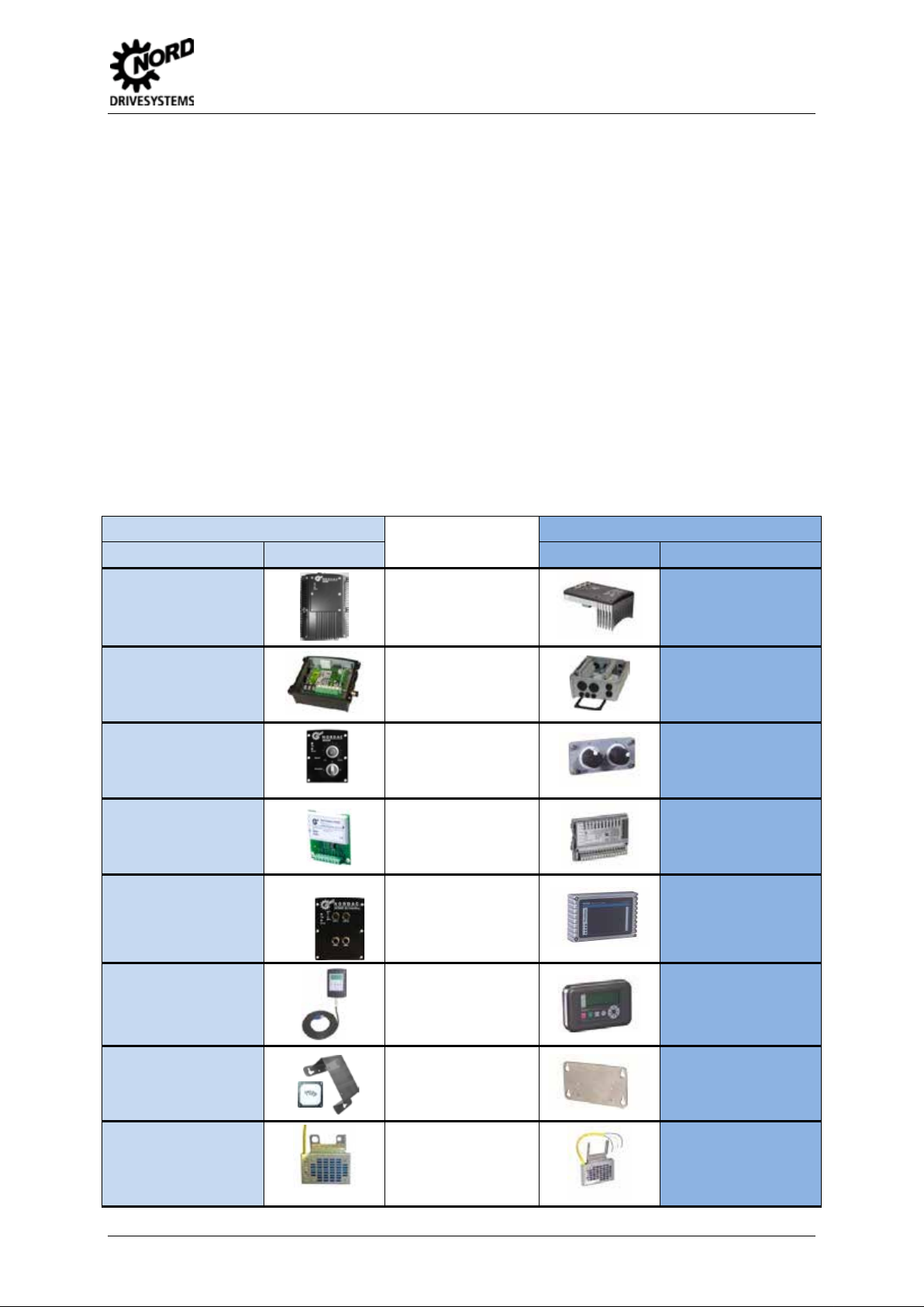
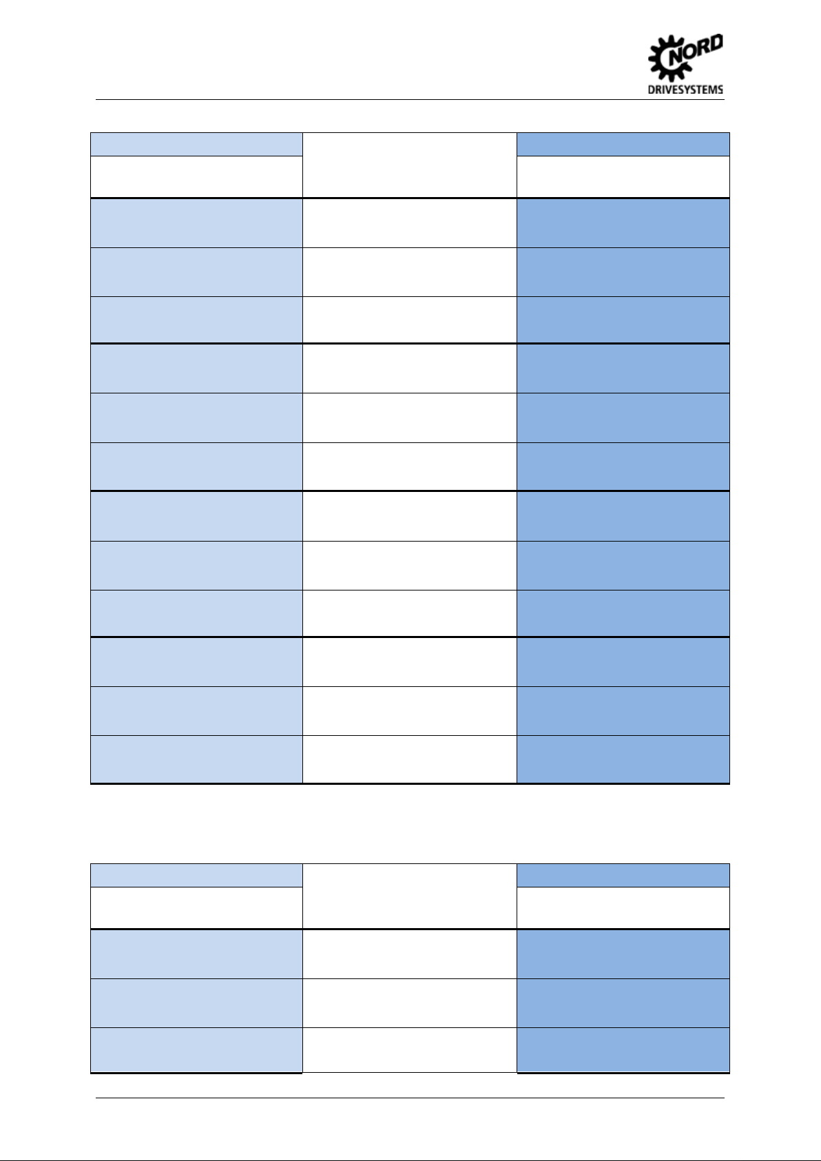
1.1 Overview of components
The following table lists and compares the individual components for the conversion of the two
different frequenc y inverter series. A distinction is m ade between the standard IP 55 version and the
"coated" IP 66 version. The details for the IP 66 versions are shown in brackets.
SK 300E
Designation Illustration Illustration Designation
SK 300E-xxx-xxx-B-(C)
SK TI 0/x-xxx-(C)
SK TU2-POT-(C)
SK CU2-xxx-(C)
SK TU2-xxx-(C)
Components
Frequency inverter
Connection unit
PotentiometerBox
Customer interface
Technology option
SK 200E
SK 200E-xxx-xxx-A-(C)
SK TI4-x-2xx-x-(C)
SK CU4-POT
SK CU4-xxx
SK TU4-xxx-(C)
SK PAR-2H
SK WMK-DA1
SK BR3-xxx/xxx
Migration Guide-GB-11.10.2012 3
Parameterbox
Wall-mounting
Braking resistor
SK PAR-3H
SK TIE4-WMK-1
SK BRE4-x-x00-x00
Page 4
Decentralised drive technology - from SK 300E to SK 200E
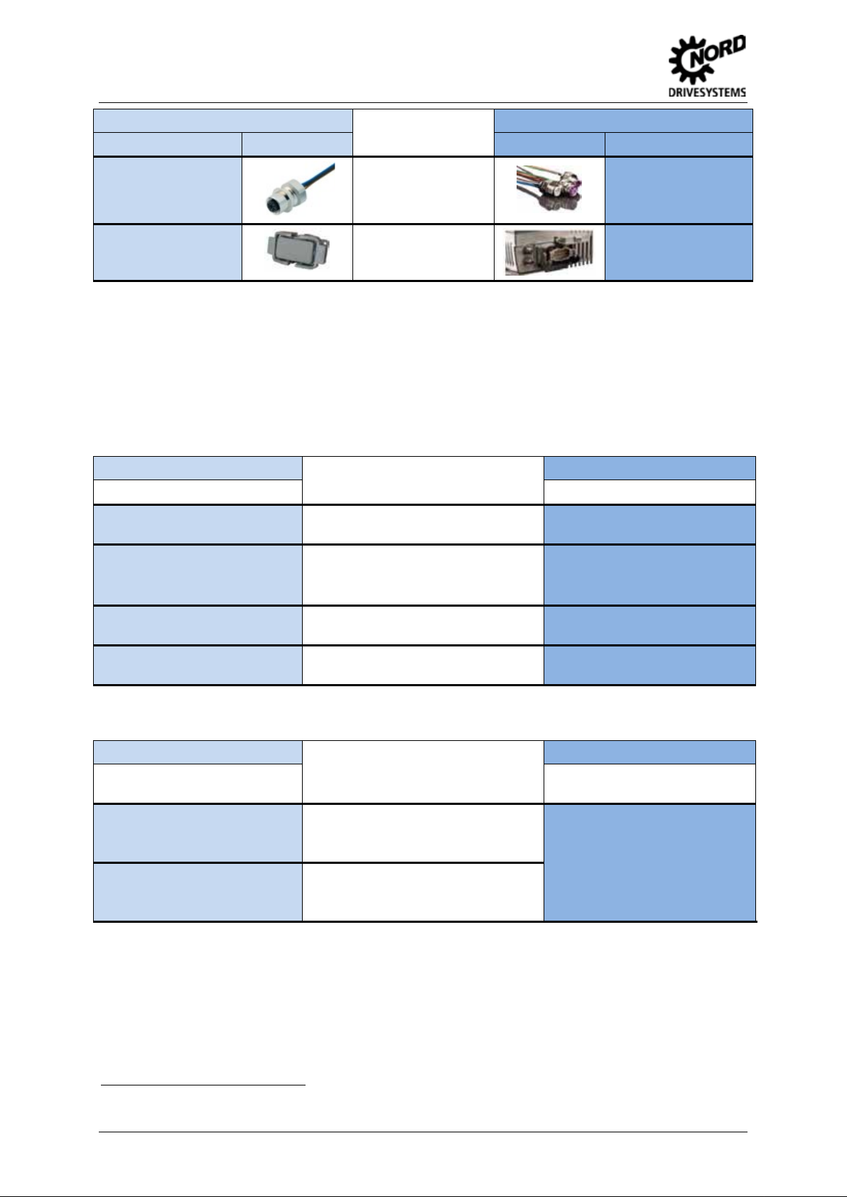
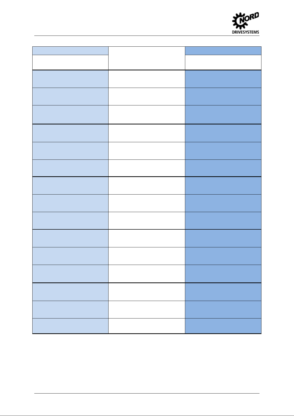
SK 300E
Designation Illustration Illustration Designation
M12 System connector
MA H10E
Table 1: Overview of components
Components
System connectors
Motor plug connector
SK 200E
SK TU4-xxx-M12
SK TIE4-HAN10E
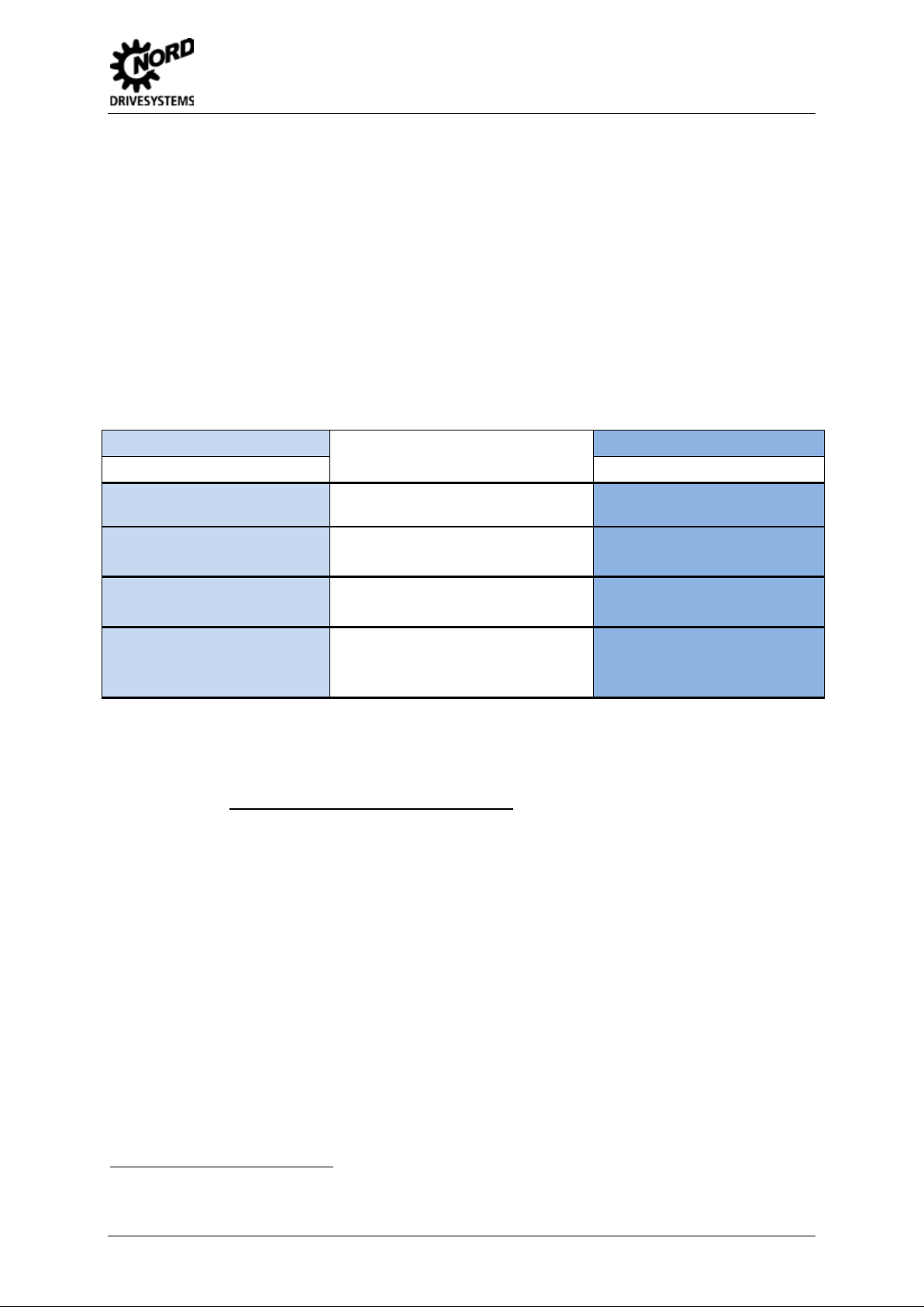
1.2 Overview of frequency inverters
The assignment of the inver ter versions according to the supply voltage a nd the rated power of the
devices is summarised below. A distinction is made between the frequency inverter and the
connection unit. The details for the IP 66 versions are shown in brackets.
SK 300E
Designation Designation
SK 300E-xxx-323-B-(C)
370W … 550W / ½ … ¾ hp
Mains type
Power level
1 phase~ 230V / 240V
SK 2xxE
SK 200E-xxx-123-A-(C)
SK 300E-xxx-323-B-(C)
SK 300E-xxx-323-B-(C)
SK 300E-xxx-340-B-(C)
Table 2: Overview of frequency inverters - Power levels
1 phase~ 230V / 240V
750W … 1.1kW / 1 … 1 ½ hp
3 phase~ 230V / 240V
370W … 550W / ½ … ¾ hp
3 phase~ 400V / 480V
550W … 4.0 kW / ¾… 5 hp
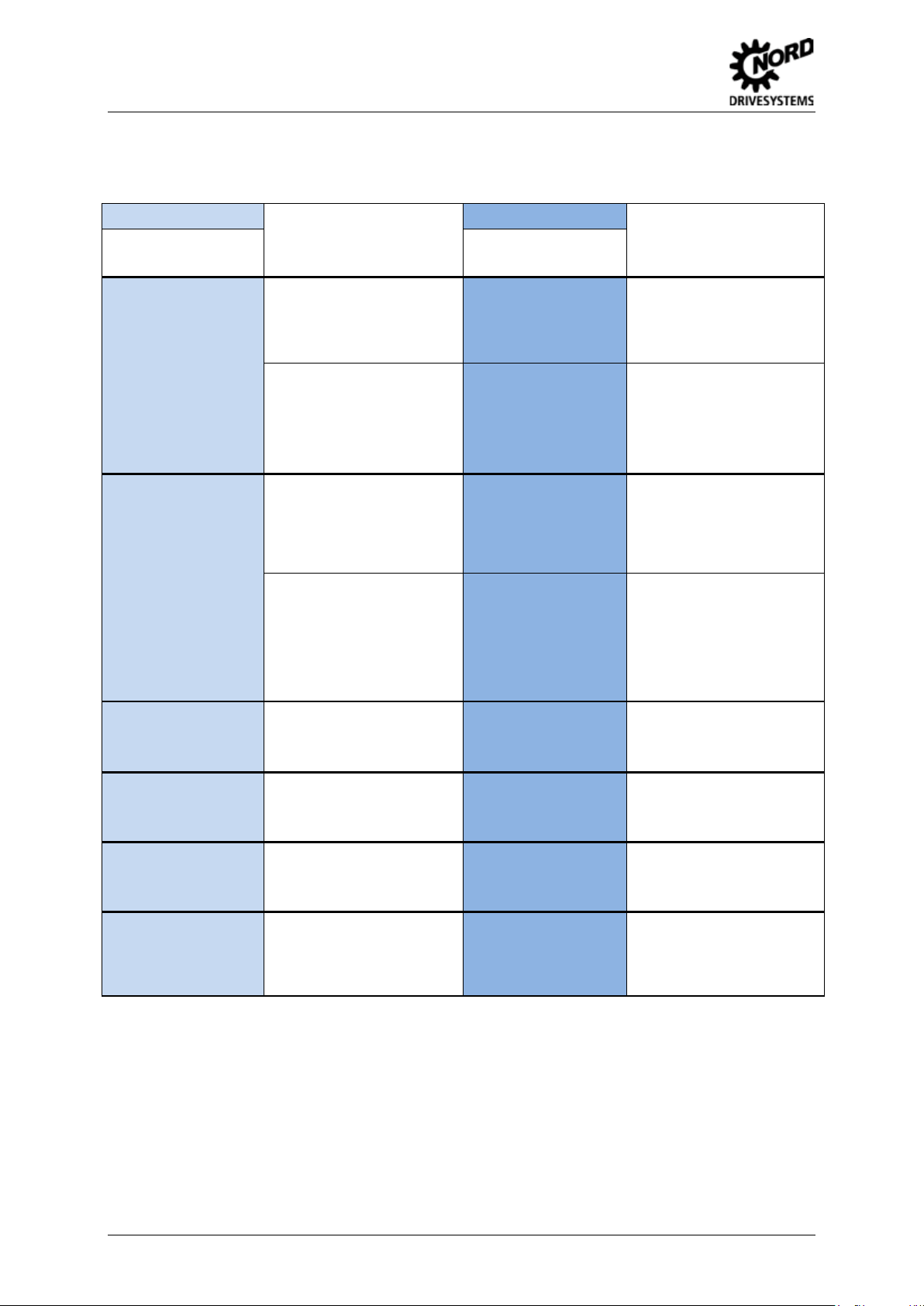
SK 300E
Designation
Note
SK TI0/1-230-(C) a
SK TI0/1-400-(C) b
SK TI0/2-230-(C) a
SK TI0/2-400-(C) b
a
for all 230V inverters; b for all 400V inverters
Table 3: Overview of connection units
For motor mounting and wall mounting.
Provides space for installation of the
Custome r Unit.
In addition:
Mounting of system plug connectors
(motor / mains connection).
Information
SK 205E-xxx-123-A-(C) 1
Attention: different frequency
inverter version!
SK 200E-xxx-323-A-(C)
SK 200E-xxx-340-A-(C)
SK 2xxE
Designation
Note
SK TI4-x-2xx-x-(C)
The connection units are directly
assigned to the frequency inverter
versions, mains tapes and power
levels.
1
higher powers are available (refer to note / Section 2.1.2)
4 Migration Guide-GB-11.10.2012
Page 5
Recoding
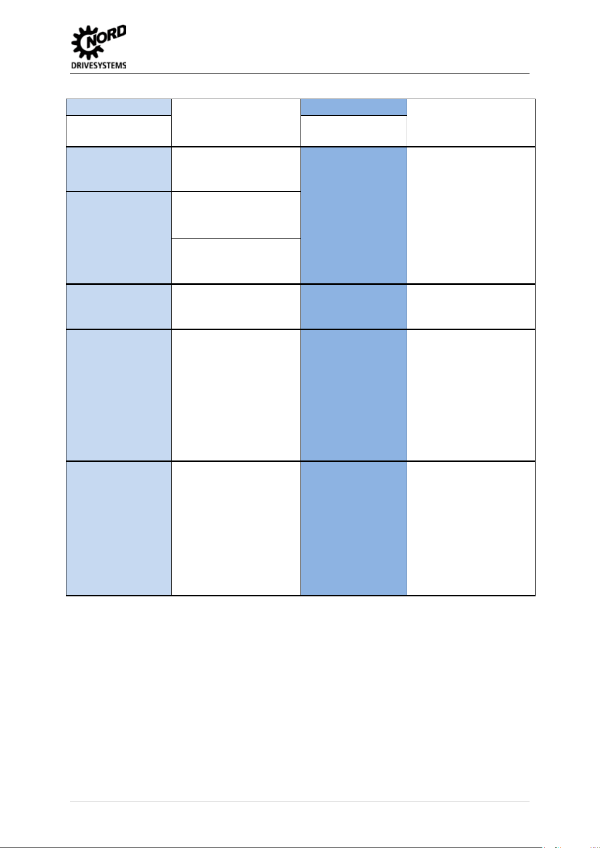
2. Recoding
SK 2xxE series frequ enc y inverter s are a vailabl e in a total of 8 d iff erent perf orm ance levels (SK 2 00E,
SK 205E, SK 210E, SK 215E, SK 220E, SK225E, SK 230E, SK 235E). In general, a distinction is
made between SK 2x0 E and SK 2x5E devices . These essentially dif fer in the available I/O s and the
control voltage supp ly (SK 2x0E - int egrated 24V m ains unit, or S K 2x5E - witho ut 24V mains u nit) or
in the features "AS interface" (SK 22xE and SK 23xE) and "Functional safety" (SK 21xE and SK
23xE). A distinction is made between the standard IP 55 ver sion and the "co ated" IP 66 version. T he
details for the IP 66 versions are shown in brackets.
2.1 Frequency inverter
2.1.1 performance levels
SK 300E
Features
Designation Designation
SK 2xxE
SK 300E-xxx-xxx-B-(C)
not available
SK 300E-xxx-xxx-B-(C)
+ SK TU2-ASx-(C)
not available
Table 4: Overview of SKL 2xxE performance levels
3
Standard
Standard
+ Functional Safety
Standard
+ AS interface
Standard
+ Functional Safety
+ AS interface
2
2
SK 20xE-xxx-xxx-A-(C)
SK 200E-xxx-xxx-A-(C)
SK 22xE-xxx-xxx-A-(C) 3
SK 23xE-xxx-xxx-A-(C)
2.1.2 Performance levels
The operation of SK 300E br ake motors with the SK 2 x0E requires an additional Custom er Interf ace
SK CU4 MBR / part number 275271010. SK 2x5E frequency inverters are equipped with an
integrated half-wave rectifier to control the electro-m echanic al brake.
The following recoding does not consider applications with AS interface functionalities. For these
applications, the corresponding SK 22xE types with their associated connection unit according to
Section 2.3 should be noted.
A distinction is m ade between the standard IP 55 version and t he "coated" IP 6 6 version. The deta ils
for the IP 66 versions are shown in brack ets .
2
corresponds to "Safe pulse block"
3
depending on the AS interface application (A/B slaves or only A slaves)
Migration Guide-GB-11.10.2012 5
Page 6
Decentralised drive technology - from SK 300E to SK 200E
SK 300E-370-323-B-(C)
SK 200E-370-123-A-(C)
275120370
275226104
(275160370)
(275226604)
SK TI 0/1 230-(C)
SK TI4-1-200-1-(C)
275270040
(275270540)
SK BRI 4-1-100-100
275272005
SK 300E-550-323-B-(C)
SK 200E-550-123-A-(C)
275120550
275226105
(275160550)
(275226605)
SK TI 0/1 230-(C)
SK TI4-1-200-1-(C)
275270040
(275270540)
SK BRI 4-1-100-100
275272005
SK 300E-750-323-B-(C)
SK 205E-750-123-A-(C)
275120750
275222106
(275160750)
(275222606)
SK TI 0/1 230-(C)
SK TI4-2-205-1-(C)
275270001
(275270501)
SK BRI 4-1-100-100
275272005
SK 300E-111-323-B-(C)
SK 205E-111-123-A-(C)
275121100
275222107
(275161100)
(275222607)
SK TI 0/1 230-(C)
SK TI4-2-205-1-(C)
275270001
(275270501)
SK BRI 4-1-100-100
SK 300E-370-323-B-(C)
SK 200E-370-323-A-(C)
275120370
275226204
(275160370)
(275226704)
SK TI 0/1 230-(C)
SK TI4-1-200-3-(C)
275270140
(275270640)
SK BRI 4-1-200-100
275272008
Power level: 1 phase 230V/240V ~
SK 300E
Designation
Part Number
SK TI 0/2 230-(C)
- Internal brake resistor
SK TI 0/2 230-(C)
- Internal brake resistor
Type / Components
Frequency inverter
370 W / ½ hp
Connection unit
Frequency inverter
550 W /
Connection unit
Frequency inverter
750 W /
¾ hp
1 hp
SK 2xxE
Designation
Part Number
SK TI 0/2 230-(C)
- Internal brake resistor
SK TI 0/2 230-(C)
- Internal brake resistor
Table 5: 1 phase 230V/240V ~
Power level: 3 phase 230V/240V ~
SK 300E
Designation
Part Number
Connection unit
Frequency inverter
1.1 kW /
Connection unit
Type / Components
Frequency inverter
370 W / ½ hp
1 ½ hp
275272005
SK 2xxE
Designation
Part Number
SK TI 0/2 230-(C)
6 Migration Guide-GB-11.10.2012
Connection unit
- Internal brake resistor
Page 7

Recoding
SK 300E-550-323-B-(C)
SK 200E-550-323-A-(C)
275120550
275226205
(275160550)
(275226705)
SK TI 0/1 230-(C)
SK TI4-1-200-3-(C)
275270140
(275270640)
SK BRI 4-1-200-100
275272008
SK 300E-750-323-B-(C)
SK 200E-750-323-A-(C)
275120750
275226206
(275160750)
(275226706)
SK TI 0/1 230-(C)
SK TI4-1-200-3-(C)
275270140
(275270640)
SK BRI 4-1-200-100
275272008
SK 300E-111-323-B-(C)
SK 200E-111-323-A-(C)
275121100
275226207
(275161100)
(275226707)
SK TI 0/1 230-(C)
SK TI4-1-200-3-(C)
275270140
(275270640)
SK BRI 4-1-200-100
275272008
SK 300E-151-323-B-(C)
SK 200E-151-323-A-(C)
275121500
275226208
(275161500)
(275226708)
SK TI 0/1 230-(C)
SK TI4-2-200-3-(C)
275270141
(275270641)
SK BRI 4-1-200-100
275272008
SK 300E-221-323-B-(C)
SK 200E-221-323-A-(C)
275122200
275226209
(275162200)
(275226709)
SK TI 0/1 230-(C)
SK TI4-2-200-3-(C)
275270141
(275270641)
SK BRI 4-1-200-100
275272008
SK 300E
Designation
Part Number
SK TI 0/2 230-(C)
- Internal brake resistor
SK TI 0/2 230-(C)
- Internal brake resistor
Type / Components
Frequency inverter
550 W /
¾ hp
Connection unit
Frequency inverter
750 W /
1 hp
Connection unit
Frequency inverter
1.1 kW /
1 ½ hp
SK 2xxE
Designation
Part Number
SK TI 0/2 230-(C)
- Internal brake resistor
SK TI 0/2 230-(C)
- Internal brake resistor
SK TI 0/2 230-(C)
- Internal brake resistor
Table 6: 3 phase 230V/240V ~
Connection unit
Frequency inverter
1.5 kW / 2 hp
Connection unit
Frequency inverter
2.2 kW / 3 hp
Connection unit
Migration Guide-GB-11.10.2012 7
Page 8
Decentralised drive technology - from SK 300E to SK 200E
SK 300E-550-340-B-(C)
SK 200E-550-340-A-(C)
275120555
275226305
(275160555)
(275226805)
SK TI 0/1,400-(C)
SK TI4-1-200-3-(C)
275270140
(275270640)
SK BRI 4-1-400-100
275272012
SK 300E-750-340-B-(C)
SK 200E-750-340-A-(C)
275120755
275226306
(275160755)
(275226806)
SK TI 0/1,400-(C)
SK TI4-1-200-3-(C)
275270140
(275270640)
SK BRI 4-1-400-100
275272012
SK 300E-111-340-B-(C)
SK 200E-111-340-A-(C)
275121105
275226307
(275161105)
(275226807)
SK TI 0/1 400-(C)
SK TI4-1-200-3-(C)
275270140
(275270640)
SK BRI 4-1-400-100
275272012
SK 300E-151-340-B-(C)
SK 200E-151-340-A-(C)
275121505
275226308
(275161505)
(275226808)
SK TI 0/1 400-(C)
SK TI4-1-200-3-(C)
275270140
(275270640)
SK BRI 4-1-400-100
275272012
SK 300E-221-340-B-(C)
SK 200E-221-340-A-(C)
275122205
275226309
(275162205)
(275226809)
SK TI 0/1,400-(C)
SK TI4-1-200-3-(C)
275270140
(275270640)
SK BRI 4-1-400-100
275272012
Power level: 3 phase 400V/480V ~
SK 300E
Designation
Part Number
SK TI 0/2,400-(C)
- Internal brake resistor
SK TI 0/2 400-(C)
- Internal brake resistor
Type / Components
Frequency inverter
550 W /
¾ hp
Connection unit
Frequency inverter
750 W /
1 hp
Connection unit
Frequency inverter
1.1 kW /
1 ½ hp
SK 2xxE
Designation
Part Number
SK TI 0/2 400-(C)
- Internal brake resistor
SK TI 0/2 400-(C)
- Internal brake resistor
SK TI 0/2 400-(C)
- Internal brake resistor
Connection unit
Frequency inverter
1.5 kW / 2 hp
Connection unit
Frequency inverter
2.2 kW / 3 hp
Connection unit
8 Migration Guide-GB-11.10.2012
Page 9

Recoding
SK 300E-301-340-B-(C)
SK 200E-301-340-A-(C)
275123005
275226310
(275163005)
(275226810)
SK TI 0/1,400-(C)
SK TI4-2-200-3-(C)
275270141
(275270641)
SK BRI 4-1-400-100
SK 300E-401-340-B-(C)
SK 200E-401-340-A-(C)
275124005
275226311
(275164005)
(275226811)
SK TI 0/1,400-(C)
SK TI4-2-200-3-(C)
275270141
(275270641)
SK BRI 4-1-400-100
275272012
SK 300E
Designation
Part Number
SK TI 0/2 400-(C)
- Internal brake resistor
SK TI 0/2 400-(C)
- Internal brake resistor
Table 7: 3 phase 400V/480V ~
Type / Components
Frequency inverter
3.0 kW / 4 hp
Connection unit
Frequency inverter
4.0 kW / 5 hp
Connection unit
SK 2xxE
Designation
Part Number
275272012
Migration Guide-GB-11.10.2012 9
Page 10
Decentralised drive technology - from SK 300E to SK 200E
SK CU2-BSC-(C)
Customer Unit Basic I/O
The analog input of the
275130010
(275170010)
If the analog input is used as
SK TU4-IOE-(C)
Use this additional
275281106
(275281156)
SK TI4-TU-BUS-(C)
275280000
(275280500)
SK CU2-STD-(C)
Customer interf. Standard I/O
1 analog / digital output
The frequency inverter does
275130020
(275170020)
If the analog output is used.
SK TU4-IOE-(C)
The analog output must be
275281106
(275281156)
SK TI4-TU-BUS-(C)
275280000
(275280500)
SK TU2-POT-(C)
Potentiometerbox
SK CU4-POT
Potentiometerbox
IP 66 = Standard
275130060
275271207
(275170060)
SK ATX-POT
ATEX potentiometer
SK ATX-POT
ATEX potentiometer
IP 66 = Standard
275142000
275142000
SK TU2-CTR-(C)
Control box
Keyboard
275130130
not available
(275170130)
SK PAR-2H
Hand-held Parameterbox
M12 plug connector
SK PAR-3H
Hand-held Parameterbox
cable
2.2 Options and components
A distinction is m ade between the standard IP 55 version and t he "coated" IP 6 6 version. The deta ils
for the IP 66 versions are shown in brackets.
SK 300E option
Designation
Part Number
Information
3 digital inputs
1 analog input 0…10V
(differential input)
a differential input.
4 digital inputs
2 analog inputs 0…10V,
0/4…20mA
(differential input)
SK 2xxE option
Designation
Part Number
SK 200E-…-A-(C)
incl.
SK 200E-…-A-(C)
incl.
Information
SK 200E is not a differenti al
input.
technology option and
connection unit if a
differential input is required.
not have an analog output.
Only 2 digital outputs are
available
implemented with one of
these additional technology
options and connection units.
278910100 275281014
Table 8: Overview of options 1
1 Potentiometer 0...100 %
1 switch left-0-right
1 potentiometer 0...100 %
10kΩ
4-digit, 7-segment LED
display
Plain text display
Keyboard
incl. Connection cable and
1 potentiometer 0...100 %
1 switch left-0-right
1 potentiometer 0...100 %
10kΩ
not available
Plain text display
Keyboard
incl. RJ12-RJ12 connection
10 Migration Guide-GB-11.10.2012
Page 11
Recoding
SK TU2-PBR-(C)
PROFIBUS DP module
connector
SK TU4-PBR-(C)
PROFIBUS DP module
275130070
275281100
(275170070)
(275281150)
SK TU2-PBR-24V-(C)
external 24V power supply
SK TI4-TU-BUS-(C)
Use with connection unit for
275130110
275280000
(275170110)
(275280500)
SK TU2-PBR-KL-(C)
8 pin terminal
SK TIE4-M12-PBR
Use optional 2 x 5-pin M12
275130065
275274500
SK TU2-IBS-(C)
INTERBUS module
connector
275130080
SK TU2-DEV-(C)
SK TU4-DEV-(C)
275130090
275281102
(275170090)
(275281152)
SK TI4-TU-BUS-(C)
275280000
(275280500)
SK TU2-CAO-(C)
CANopen module
SK TU4-CAO-(C)
CANopen module
275130100
275281101
SK TI4-TU-BUS-(C)
275280000
SK TIE4-M12-CAO
275274501
More recent software files are required for the field bus technology option SK TU4-xxx-(C).
SK 300E option
Designation
Part Number
(275170065)
(275170080)
Information
Baud rate: 1.5 MBit/s
2 x 5-pin M12 system plug
Baud rate: 12 MBit/s
2 x 5-pin M12 system plug
connector
Baud rate: 1.5 MBit/s
Baud rate: 500 kBit/s
2 x 5-pin M12 system plug
DEVICENET module
Baud rate: 500 kBit/s
1 x 5-pin M12 system plug
connector
SK 2xxE option
Designation
Part Number
Baud rate: 12 MBit/s
Technology box.
system plug connector
not available not available
DEVICENET module
Baud rate: 500 kBit/s
Use with connection unit for
Technology box.
Information
SK TIE4-M12-CAO Use optional 1 x 5-pin M12
275274501
Baud rate: 1 MBit/s
(275170100) (275281151)
Table 9: Overview of options 2
2 x 5-pin M12 system plug
connector
(275280500)
system plug connector
Baud rate: 1 MBit/s
Use with connection unit for
Technology box.
Use optional 1 x 5-pin M12
system plug connector
Migration Guide-GB-11.10.2012 11
Page 12

Decentralised drive technology - from SK 300E to SK 200E
SK TU2-AS1-(C)
actuators.
275130120
(275170120)
SK TIE4-M12-ASI
275274502
SK TIE4-M12-INI
SK TU2-AS3-(-C)
AS interface module
AS interface module
actuators.
275130125
SK TIE4-M12-ASI
275274502
SK TIE4-M12-INI
2.3 AS Interface
Ø If the technology option SK TU2-ASx of the SK 300E is only used as an I/O extension, the SK
20xE must be used with an additional technology option SK TU4-IOE-(C) and the appropr iat e
connection unit SK TI4-TU-BUS-(C).
Ø SK 300E with SK TU2-AS1-(C): The "extended string transfer" (refer to BU 0090) cannot be
implemented with the SK 22xE.
Ø SK 300E with SK TU2-AS3: The SK 220E must be used in order to utilise the A/B slave
functionality.
Ø SK 225E: The power consumption of the frequency inverter is 290 mA. The AS interface
mains unit (PELVI) must be dimensioned accordingly. In addition, the supply for further
sensors or actuators must be taken into account.
Ø SK 22xE: The optional M12 system plug connector SK TIE4-M12-ASI must always be planned
for the connection of the AS interface cable.
Ø For the connection of digital inputs and digital outputs via the flanged sockets of the SK TU2-
ASx the additional M12 system plug connector SK TIE4-M12-INI is available for connection to
the SK 2xxE.
SK 300E option
Designation
Part Number
(275170125)
Information
AS interface module
2 x 5-pin M12 system plug
connector for ASI and AUX
2 x 5-pin M12 system plug
connector socket for
additional digital inputs and
digital outputs
Slave profile S 7.4.0
2 x 5-pin M12 system plug
connector for ASI and AUX
2 x 5-pin M12 system plug
connector socket for
additional digital inputs and
digital outputs
Slave profile S 7.A
SK 2xxE option
Designation
Part Number
SK 225E-…-(C) incl.
plus
SK TI4-x-225-x-(C)
275274503
SK 200E-…-(C)4 incl.
plus
SK TI4-x-220-x-(C)
275274503
Information
AS interface module
is integrated.
Slave profile S 7.0
Use the optional 1 x 5-pin
M12 system plug
connector to connect the
AS interface cable and the
1 x 4-pin M12 system plug
connect the sensors or
is integrated.
Slave profile S 7.A
Use the optional 1 x 5-pin
M12 system plug
connector to connect the
AS interface cable and the
1 x 4-pin M12 system plug
connect the sensors or
Table 10: Overview of AS interface options
4
Only SK 225E FIs are available for single phase 230V applications with powers of 0.75kW and 1.1kW.
12 Migration Guide-GB-11.10.2012
Page 13

Recoding
SK BR3-82/200-TI 0/1
SK BRE 4-1-200-100
275140020
275273008
SK BR3-82/200-TI 0/2
275140040
SK BR3-120/100-TI 0/1
External braking resistor
SK BRE 4-1-400-100
External braking resistor
275140010
275273012
275140030
SK BR3-82/200-TI 0/1
External braking resistor
SK BRE 4-2-200-200
External braking resistor
2.4 External braking resistor
If the SK 300E application does not have an ex ternal braking res istor, an interna l braking resistor SK
BRI4-x-xxx-xxx must be used with the SK 2xxE
If the SK 300E application has an external braking re sistor SK BR3-xxx/xxx-TI x/x, the SK 2xxE must
be equipped with an external brak ing resistor SK BRE 4-x-xxx-xxx according to t he following ta ble. In
this case, the internal braking resistor may not be used with the SK 2xxE.
The external braking resistors for the SK 2xxE generally have protection class IP 67.
SK 300E
Braking resistor
Designation
Part Number
Information
External braking resistor
for
SK 300E-370-323-B-(C) …
SK 300E-221-323-B-(C)
Braking resistor
82 Ω resistor
200 W continuous output
2.0 kW pulse output
for
SK 300E-550-340-B-(C) …
SK 300E-151-340-B-(C)
SK BR3-120/100-TI 0/2
275140020 275273108
120 Ω resistor
100 W continuous output
1.0 kW pulse output
for
SK 300E-221-340-B-(C) …
SK 300E-401-340-B-(C)
SK BR3-82/200-TI 0/2
275140040
82 Ω resistor
200 W continuous output
2.0 kW pulse output
SK 2xxE
Designation
Part Number
Information
External braking resistor
for
SK 2xxE-370-323-A-(C) …
SK 2xxE-221-323-A-(C)
200 Ω resistor
100 W continuous output
2.2 kW pulse output
for
SK 2xxE-550-340-A-(C) …
SK 2xxE-221-340-A-(C)
400 Ω resistor
100 W continuous output
2.2 kW pulse output
for
SK 2xxE-301-340-A-(C) …
SK 2xxE-401-340-A-(C)
200 Ω resistor
200 W continuous output
4.4 kW pulse output
Table 11: Overview of external braking resistors
Migration Guide-GB-11.10.2012 13
Page 14

Decentralised drive technology - from SK 300E to SK 200E
SK ATX-POT
ATEX potentiometer
SK ATX-POT
ATEX potentiometer
275142000
275142000
SK EU2-ATX1
SK 200E-ATEX-BG1
SK EU2-ATX2
275141010
SK 200E-ATEX-TU4
ATEX outdoor installation
SK TU4-xxx-(C)
SK WMK-DA1
SK TIE4-WMK-1
construction, the SK 2xxE has different derating characteristics according to the type of mounting
mounted). Under certain circumstances this requires the selection of a higher power
essary. Therefore the technical data of the frequency inverter
2.5 ATEX
The planning of ATEX drives must be ch eck by Getriebebau NORD!
SK 300E
Designation
Part Number
275141000
- not available
Table 12: ATEX overvie w
Information
10kΩ
ATEX kit for
size 1
ATEX kit for
size 2
SK 2xxE
Designation
Part Number
275274200
275274206
Information
10kΩ
ATEX outdoor installation
kit
for frequency inverters size
1 and 2
kit
for technology options
The ATEX potentiom eter S K ATX -POT (also k nown under the d esignati on SK EU2-POT) can be used
for both frequency inverter series.
The options which are approved for ATEX applications are listed in the manual BU 0200.
2.6 Wall-mounting kit
SK 300E
Wall-mounting
Designation
Part Number
Wall-mounting kit
275115100 275274000
Table 13: Wall-mounting overview
Information
The adapter kits for motor sizes S 63 and S 71 are identical for both frequency inverter series.
Information
Due to its
(motor-mounted / wallfrequency inverter than that which is nominally nec
(refer to manual BU0200) must be taken into account.
SK 2xxE
Wall-mounting
Designation
Part Number
Derating
Information
Wall-mounting kit
14 Migration Guide-GB-11.10.2012
Page 15

Power and and control terminal connection
-B +B
-Br +Br
U V W
L1 L2 L3
Option
Customer unit
Earth "PE"
(connection of mains line)
Mains voltage:
3~ 400V / 3~ 230V
1
) 1~ 230V, 0,37
-0,75kW
2
) 1~ 230V, 1,1kW
Mechanical brake
External brake resistor
The polarity can be ignored.
Earth "PE"
(Additional PE terminal, e.g. for
control line, braking resistor)
Motor
3~
PE- socket = 3~ 400V device
PE- connector
= 3~ 230V device
PE L1 L2 L3
1
( PE L N - )
2
( PE - N L )
L1 / L
L2 / N
L3 / PE
PE L3 L2 L1
M
3~
PE U V W +B -B
Internal or
external
breaking resistor
3. Power and and control terminal connect ion
3.1 Power connection
Fig. 1: Assignment of connection unit SK TI 0/x-(C) for SK 300E
Fig. 2: Assignment of the connection unit SK TI4-x-2xx-x-(C) for SK 2xxE
Migration Guide-GB-11.10.2012 15
Connecting an electro-mechanical brake
SK 2x0E
Terminals 79 (MB+) and 80 (MB-) of the
customer interface SK CU4-MBR
SK 2x5E
Terminals 79 (MB+) and 80 (MB-) of the control
terminal bar of the frequency inverter
Page 16

Decentralised drive technology - from SK 300E to SK 200E
3.2 Control terminal connection
SK 300E
Function / Meaning
Terminal bar Terminal number Terminal bar
SK TI 0/x-(C)
Control
connections
Connection unit
21
Digital input 1
Thermistor
41 + 5V supply voltage 38
40 0V, GND 40
SK TI4-x-2xx-x-(C)
control terminal bar
42 + 15V supply voltage
74 RS 485 interface B (-) R J12 contr ol bloc k 2
73 RS 485 interface A (+) 1
SK TI4-x-2xx-x-(C)
control terminal bar
control terminal bar
SK CU2-BSC-(C)
Customer interface
01 Signal relay (error)
02 Signal relay
11 Reference voltage + 10V SK TI4-x-2xx-x-(C)
12 0V, AGND 12 13 Analog input - SK TU4-IOE-(C)
14 Analog input + 3
I/O extension
22 Digital input 2 SK TI4-x-2xx-x-(C)
23 Digital input 3 23
control terminal bar
SK 200E
Terminal number
SK 2x0E SK 2x5E
5
44 5
43
5
44 5
43
11 -
39
1
22
6
4
24 Digital input 4 24
SK CU2-STD-(C)
Customer interface
42 Supply voltage + 15V
11 Reference voltage + 10V SK TI4-x-2xx-x-(C)
12 0V, AGND 12 -
control terminal bar
14 Analog input 1 14 16 Analog input 2 16 -
17 Analog output 1
SK TU4-IOE-(C)
I/O extension7
22 Digital input 2 SK TI4-x-2xx-x-(C)
23 Digital input 3 23
control terminal bar
24 Digital input 4 24
25 Digital input 5
42 Supply voltage + 15V
SK TU4-IOE-(C)
I/O extension
SK TI4-x-2xx-x-(C)
control terminal bar
5
24V supply internal with SK 2x0E, external with SK 2x5E
6
Attention: This in not a potential-isolated relay output, but rather only a digital output!
7
if there is no SK CU4-MBR with SK 2x0E …-(C) →use SK CU4-REL / part number 275271011
5
44 5
43
11 -
9
7 (0V-A)
22
19
11 (24V)
5
44 5
43
16 Migration Guide-GB-11.10.2012
Page 17

Power and and control terminal connection
SK 300E
Function / Meaning
Terminal bar Terminal number Terminal bar
SK BRE3-xxx-xxx
Braking resistor
SK TU2-POT-(C)
Control
connections
PotentiometerBox
SK TI 0/x-(C) External braking resistor
- B Braking resistor -
+ B Braking resistor + + B
Potentiometer 0...100%
switch left-0-right
24V- supply voltage 43 44
Enable right (e.g. DIN1) 21 -
Plug contacts
Enable left (e.g. DIN2) 22 -
SK BRx4-x-x00-x00
Braking resistor
SK CU4-POT
Potentiometer adapter
IP 66
Access to AIN +
Reference voltage 10V 11
SK ATX-POT
ATEX
potentiometer
SK CU2-xxx-(C)
11 + 10V 11
AGND analog ground 12
Potentiometer 0…100 %
10 kΩ
SK ATX-POT
ATEX potentiometer
SK 200E
Terminal number
SK 2x0E SK 2x5E
8
SK TI4-x-2xx-x-(C)
SK 2x0E SK 2x5E
SK 2x0E SK 2x5E
- B
14
Refer to
9
SK PAR-2H
Parameterbox
SK TU2-PBR-...-(C)
Technology unit
Profibus DP
24V –B / Bus supply
Refer to BU 0020 for
the relevant technology
unit for the conn ect i o n
assignments
12 AGND / 0V
14
M12 flanged socket
on the SK TI 0/x-(C)
connection unit
Analog input +
Analog input 1
Parameterisation box / Control
unit
SK PAR-3H
Parameterbox
RJ12 plug with cable
RS485
Plug contacts Profibus DP field bus option SK TU4-PBR-(C)
Profibus DP module
Refer to BU 0220 for
connection as signments
M12 round plug
connectors
B coded
Profibus DP cable B IN 3
Profibus DP cable B OUT 4
Profibus DP cable A IN
Profibus DP cable A OUT M12 flanged
0V-B / (0V Profibus DP voltage)
connector
Socket and plug
RTS 9
+5V B / (5V Profibus DP voltage) 10
12 or 40
14 or 16
Refer to
Refer to
9
9
RJ12 interface on
SK
2xxE…-(C) or on
the connection unit
SK TI4-TU-BUS-(C)
Terminal bar
SK TI4-TU-BUS-(C)
1 + 2
5
6
7 + 8
8
With the SK 2xxE the internal braking resistor SK BRI4-1-x00-x00 is connected to the same terminals.
9
For connection to SK 2x5E …-(C) frequency inverters either a customer interface mains unit option SK CU4-
24V-xxx-B or a SK CU4-IOE IO extension is required!
Migration Guide-GB-11.10.2012 17
Page 18

Decentralised drive technology - from SK 300E to SK 200E
Terminal bar
10
11
SK 300E
Function / Meaning
Terminal bar Terminal number Terminal bar
SK TU2-DEV-...-(C)
DeviceNet
technology unit
24V –B / Bus supply
Plug contacts DeviceNet field bus option SK TU4-DEV-(C)
DeviceNet module
Refer to BU 0280 for
connection as signments
M12 round plug
connectors
A coded
DeviceNet High IN 3
DeviceNet High OUT 4
DeviceNet Low IN 5
Refer to BU 0080 for
connection
assignments
DeviceNet Low OUT M12 Flanged connector
0V-B / Data ground Bus 7 + 8
Plug connector
SHLD / Bus cable shielding 9
PE / Bus cable bonding
conductor
SK TU2-CAO-..-(C)
Technology unit
Profibus DP
Plug contacts CANopen field bus option SK TU4-CAO-(C)
M12 round plug
connectors
A coded
24V –B / Bus supply
CAN High IN 3
CANopen module
Refer to BU 0260 for
connection assignments
CAN High OUT 4
Plug connector
Refer to BU 0060 for
connection
assignments
CAN Low IN 5
CAN Low OUT M12 Flanged connector
0V-B / Data ground Bus 7 + 8
SK 200E
Terminal number
SK 2x0E SK 2x5E
Terminal bar
SK TI4-TU-BUS-(C)
SK TI4-TU-BUS-(C)
1 + 2
6
10
1 + 2
6
SHLD / Bus cable shielding 9
PE / Bus cable bonding
conductor
SK TU2-ASx-...-(C)
AS interface
technology unit
Refer to BU 0020 for
the relevant technology
unit for the conn ect i o n
assignments
Plug contacts AS interface field bus option /
SK 220E / 225E ...-(C) with
integrated ASI interface
M12 round plug
connectors
A coded
AS-i (+)
AS-i (-) 85
AUX GND
AUX 24V
ASI / Digital input 1
ASI / Digital input 2
SK TI4-x-22x-x-(C)
control terminal bar
Refer to BU 0200 for
connection as signments
M12 Flanged connector
Plug connector
SK TI4-x220-x-(C)
ASI / Digital input 3
ASI / Digital input 4
ASI / Digital output 1 1
ASI / Digital output 2 3
Table 14: Overview of control terminals
10
The 24V supply is via the yellow AS interface cable (terminals 84 and 85)
11
Con only be implemented with an additional SK TU4-IOE-(C).
18 Migration Guide-GB-11.10.2012
10
SK TI4-x225-x-(C)
84
Not required
Not required
21
22
23
24
10
-
Page 19

Power and and control terminal connection
Control connections:
[21] Dig. Input 1
(PTC input) (*)
[41] + 5V supply voltage
[40] 0V, GND
[41] + 5V supply voltage
[40] 0V, GND
[42] + 15V supply voltage
[74] RS 485 interface: B (-)
[73]
RS 485 interface: A (+)
Termination resistor RS 485 On/Off
[02] Signal relay (error)
[01] Signal relay
[…] = Terminal No.
-B +B
-Br +Br
U V W
L1 L2 L3
Option
Customer unit
System connector M12 socket
Mechanical brake
External brake resistor
The polarity can be ignored.
(*) The digital inputs can be connected
with the internal 15 V or from the PLC
(7.5 – 33V DC). The data in "(...)"
represent the factory settings.
Customer si de
Reference voltag e +10 V (max. 10 mA)
[11]
AGND, 0V [12]
Analog input - [13]
Analog input + [14]
Digital input 2 [Enable right]
[22]
Digital input 3 [Enable left] [23]
Digital input 4 [Parameter set switching] [24]
Supply voltage +15 V (m ax. 100 mA) [42]
0...10V, 0/4…20mA
or
potentiometer:
2,0kΩ...10kΩ
Floating c ontacts or
output of a PLC:
7,5...33V (low=0...3,5V)
(Maxim um te rm inal cr oss-section: 1, 5 m m ²)
Customer side
Reference voltage
+10 V (max. 10 mA)
[11]
AGND / 0V [12]
Analog input
1
[14]
Analog input 2 [16]
Analog output 1 [17]
Digital input 2 [Enable right] [22]
Digital input 3 [Enable left] [23]
Digital input 4 [Parameter set switching] [24]
Digital input 5 [fixed frequency 1]
[25]
Supply voltage +15 V (max. 100 mA) [42]
0...10V, 0/4…20mA
or
potentiometer:
2,0kΩ
...10kΩ
Floating contact or
PLC output:
7,5...33V (low=0...3,5V)
(Maximum terminal cross-section
: 1,5 mm²)
More recent software files ( GSD, EDS) are required for the field bus technol ogy option SK TU4-xxx(C). Information about the master data for the device can be found in Section 5. Further software
planning information for conversion to the technology options for SK 2xxE frequency inverters can also
be found there.
3.2.1 Details of control terminals for connection units and customer interfaces
Fig. 3: Control terminals for connection unit SK TI 0/x-(C) for SK 300E
Fig. 4: Control terminals for customer interface SK CU2-BSC-(C) for SK 300E
Fig. 5: Control terminals for customer interface SK CU2-BSC-(C) for SK 300E
Migration Guide-GB-11.10.2012 19
Page 20

Decentralised drive technology - from SK 300E to SK 200E
ASI: Integrated AS interface
24V: 24V power supply
AGND: Reference potential for analog signals
GND: Reference potential for digital signals
DIN: ‚Digital input‘, digital output
DOUT: ‚Digital output‘, digital output
MB+/-: Control of electro-magnetic brake
(105V, 180V, 205V)
TF+/-: Motor t herm i st or (PTC) connection
Fig. 6: Control terminals of the connection unit SK TI4-x-2xx-x-(C) for SK 2xxE
Connections and functions for SK 2xxE versions depending on configuration level
SK 200E SK 220E FI type SK 205E SK 225E
(ASI)
Labelling
Pin
(ASI)
24V (internal, output max. 200mA)
Analog input 1 ASI+, AS interface
Analog input 2
AGND, Reference
potential for analog
ASI-, AS interface
signals
DIN1 / digital input 1
DIN2 / digital input 2
DIN3, digital input 3
DIN4, digital input 4
GND
DOUT1, digital output 1
GND
10V Reference voltage
DOUT2, digital output 2
GND
TF+, motor PTC connection
TF-, motor thermistor (PTC) connection
43
14/84
16
12/85
21
22
23
24
40
1
40
11
3
40
38
39
1
2
3
4
5
6
7
8
9
10
11
14
15
16
17
18
44
44/84
40
40/85
21
22
23
24
40
1
40
79
80
38
39
24V, external 24V FI supply 12
24V, external 24V
FI supply
ASI+, AS interface
GND, reference potential for digital
signals
GND ASI-, AS interface
DIN1 / digital input 1
DIN2 / digital input 2
DIN3, digital input 3
DIN4, digital input 4
GND
DOUT1, digital output 1
GND
--MB+, electromagnetic brake control
MB-, electromagnetic brake control
TF+, motor thermistor (PTC) connection
TF-, motor thermistor (PTC) connection
Table 15: Overview of SK 2xxE control terminals
12
With the use of the AS interfac e, terminal 44 provides an output voltage (24V, max. 60mA). In this case, no
voltage source may be connected to this terminal!
20 Migration Guide-GB-11.10.2012
Page 21

Power and and control terminal connection
PE
PE
L2
L1
40
B1
12
14
11
40
44
40
44
…
23
… … … … …
40
44
SK CU4-
SK 2x5E-
Parameterisation of the customer interface and the field bus technology options can be carried out
either via DIP switches or via i nd ivid ual par ameters. Further detai ls c an b e f ound in th e s up plementary
manuals for the relevant technology option (BU 02x0) or in the manual BU 0200.
Mains unit SK CU4-24V-...-B
With SK 2x5E applications this customer interface can be mounted direc tly in the connection unit as
the mains unit for the 24V supply to the control electronics.
Fig. 7: Customer interface SK CU4-24V-…-B for SK 2x5E
10V REF
AIN1 +
AGND / 0V
24V
GND / 0V
DOUT
L1
Connection of the 24V power
supply from the SK 2x5E
Pulse output, connection t o the
SK 2x5E
Potential level: 24V DC
Potential level: ~ Mains
Mains voltage
(L1 with integrated fuse element T-5A)
Jumper-integrated mains filter :
Illustration: mains filter active
Connection to the terminal bar
of the SK CU4-24V-…
Fig. 8: Control terminals of customer interface SK CU4-24V-…-B for SK 2x5E
Migration Guide-GB-11.10.2012 21
Page 22

Decentralised drive technology - from SK 300E to SK 200E
R21
R22
R24
R11
R12
R14
40
C2
C1
118
117
116
114
111
112
44
R11 / R12 = NC
SK CU4-
SK 2x0E-
signals
…
11
12*
44
1
16
14 … 40
3
R21 / R22 = NC
Setpoint converter SK CU4-REL
This customer interface can be used instead of the electronic brake rectifier SK CU4-MBR for SK
2x0E applications in which an electro-mechanical brake does not need to be controlled.
The setpoint converter S K CU 4-REL en ables the di gital o utput sign al (DO) of the fr equenc y inverter to
be converted into potential-isolated relay outputs.
Also, by means of this customer interface bipolar an alog signals can be converted to 0-10V analog
signals, which in turn can be processed by the SK 2x0E frequency inverter.
Fig. 9: Customer interface SK CU4-REL for SK 2xxE
24V
AGND / 0V
10V REF.
AIN1
AIN2
AOUT1
AOUT2
DI1
DI2
GND / 0V
Fig. 10: Control terminals of customer interface SK CU4-REL for SK 2xxE
Connection of the 24V power
supply from the SK 2x0E
* Terminal 12 or Terminal 40
Connection for bipolar analog
AOUT connection of the SK
Potential level: Analog
Potential level: Digital / Relay
Control of digital IN of the SK CU4
via DO from the SK 2x0E
Relay 1
R11 / R14 = NO
Relay 2
R21 / R24 = NO
Connection to the terminal bar
of the SK CU4-REL-…
22 Migration Guide-GB-11.10.2012
Page 23

Power and and control terminal connection
L1
B
L1
B
L1
E
L1
E
79
80
B5
C5
40
44
…
1
40
44
SK CU4-
SK 2x0E-
DO from the SK 2x0E
brake from the DO of SK CU4
Potential level: = Brake
Electronic brake rectifier, SK CU4-MBR
This customer interface must be used for controlling an electro-magnetic brake in SK 2x0E
applications and is mounted directly in the connection unit.
Fig. 11: Customer interface SK CU4-MBR for SK 2xxE
24V
GND / 0V
DIN
DO
MB-
MB+
L1 380…500V~
L1 200…275V~
L2/N
L2/N
L2 / N
Fig. 12: Control terminals of customer interface SK CU4-MBR for SK 2xxE
Connection of the 24V power
supply from the SK 2x0E
Digital control in the SK CU4 via
Feedback of operating status of the
Potential level: 24V DC
Connection of DC brake coil
Potential level: = Brake
Potential level: ~ Mains
Mains voltage
(Select connection according to voltage)
Connection to the terminal bar
of the SK CU4-MBR-…
Migration Guide-GB-11.10.2012 23
Page 24

Decentralised drive technology - from SK 300E to SK 200E
3.2.2 Details of control terminals for the technology options
I/O extension SK TU4-IOE-(C)
With SK 2xxE applicat io ns, this tec h nol ogy option can be used to c on nec t a ddi tional digital and anal og
IO signals and is mounted on the frequency inverter with an additional connection unit.
Fig. 13: Technology option SK TU4-IOE-(C) and SK TI4-TU-BUS for SK 2xxE
Potential level: analog I/O
Analog IOs
System bus level and digital inputs Digital outputs
Potential level: system bus Potential level: DOs
10V-A
AIN1
AIN1 - 0V-A AOUT
+
24V
24V
(as 11)
0V 0V DIN 1 0V
24V
(as 11)
DIN 2 0V
24V
(as 11)
24V 2
DO 1 0V 2
1 3 5 7 9 11 13 15 17 19 21 23 25 27 29 31 33 35
2 4 6 8 10 12 14 16 18 20 22 24 26 28 30 32 34 36
10V-A
AIN2 + AIN2-
Fig. 14: Control terminals of technology option SK TU4-IOE-(C) for SK 2xxE
0V-A
PE
24V
Sys + Sys - 0V DIN 3 0V
(as 11)
24V
(as 11)
DIN 4 0V
24V
(as 11)
0V 2
DO 2 0V 2
Fig. 15: Connection example for technology option SK TU4-IOE-(C) for SK 2xxE
24 Migration Guide-GB-11.10.2012
Page 25

Power and and control terminal connection
Terminal 84 / AS +
Terminal 85 / AS -
Option:
AS Interface
M12 flanged plug
Option: Sensor/Actuator
M12 flanged plug
AS interface SK TU2-ASx-(C) or SK 22xE-…-(C)
Socket I/O 1
1 AUX 24V
2 Dig In 1
3 AUX GND
4 Dig Out 1
5 Dig In 3
Connector PWR
1 AS-i (+)
2 AUX GND
3 AS-i (-)
4 AUX 24V
5 n.c.
Fig. 16: Technology option SK TU2-ASx-(C) for SK 300E and pin assignment
Socket I/O 2
1 AUX 24V
2 Dig In 2
3 AUX GND
4 Dig Out 2
5 Dig In 4
Connector AUX
1 AUX 24V
2 n.c.
3 AUX GND
4 n.c.
5 n.c.
Fig. 17: AS interface connection for SK 22xE-…-(C)
An M12 flanged plug connector, type SK TIE4-M12-AS1 / part number 275274502 is available for
connecting the AS int e rfac e ca ble (y ellow cabl e) t o the t er min al s o f t he cont rol te rminal b a r o f the S K 22 xE.
M12 flanged sockets type SK TIE4-M12-INI / part 275274503 are available for the connection of
sensors and actuators to terminals 84 and 85 of the control terminal bar of the SK 22xE.
Migration Guide-GB-11.10.2012 25
Page 26

Decentralised drive technology - from SK 300E to SK 200E
POW / part number 275274507 is available for
See below for the pin
PBR / part number 275274500 are
Profibus DP SK TU2-PBR-24V-(C) or SK TU4-PBR-(C)
SK 300E SK 2xxE
SK TU2-PBR-24V(-C) SK TU4-PBR(-C) SK TI4-TU-BUS(-C)
Information bout th e o ther two technolog y opt ions S K T U 2- PBR-(C) and SK T U 2-KL-…-(C) for the SK
300E can be found in manual BU 0020. Only the 24V version of the SK 300E is described here.
24V dc connection assignments
M8 pin Signal
An M12 flanged plug connector type SK TIE4-M12-
connecting the 24V supply voltage for the SK TU4-
1
3 GND
4 n.c.
Fig. 18: M8 socket pin assignment for the 24V supply for SK TU2-PBR-24V-(C)
24V DC ±25%
PBR-(C) technology option.
assignment.
The M12 flanged sock et an d pl ug c on nec tor type type
Standard assignment
M12 pin Signal
1 + 5V
2 A Data
3 GND
4 B Data
5 n. c.
Fig. 19: M12 socket and plug connector pin assignment for the Profibus DP connection to SK TUx-PBR-
SK TIE4-M12available for connectio n the DP Bus c able. See b elo w
for the pin assignment.
To be connected to the terminals
of the control terminal bar of the
technology option
Fig. 20: M12 flanged connector SK TIE4-M12-PBR for SK 2xxE
26 Migration Guide-GB-11.10.2012
SK TU4-PBR(-C), refer to
14: Overview of control terminals
Table
Page 27

In this document a detailed description is given for the field bus systems AS interface and Profibus DP as
examples for all field bus systems which are available from NORD. For information about the DeviceNet and
Voltage
24V DC
PROFIBUS
X-1
PROFIBUS
X+1
Potential level: field bus
Power and and control terminal connection
Potential level: system bus Potential level: DOs
Field bus level
System bus level and digital inputs Digital outputs
PROFIBUS DP
PB B
24V
PB A
IN
0V-B RTS
IN
24V
(as
for 1)
24V
(as
for 1)
0V
GND
0V
GND
DIN 1
0V
GND
24V
(as
for 1)
DIN 2
0V
GND
24V
(as
for 1)
24V 2
DO 1
1 3 5 7 9 11 13 15 17 19 21 23 25 27 29 31 33 35
2 4 6 8 10 12 14 16 18 20 22 24 26 28 30 32 34 36
24V
PB B
PB A
0V-B
(as
for 1)
OUT
OUT
(as
for 8)
+5V B
24V
Sys + Sys -
(as
for 1)
0V
GND
DIN 3
0V
GND
24V
(as
for 1)
DIN 4
0V
GND
24V
(as
for 1)
0V 2 DO 2
Fig. 21: Control terminals of technology option SK TU4-PBR-(C) for SK 2xxE
SK 205E…-Conn ec ti o n u nit (S K TI4 … )
0V 2
0V 2
SK TU4-PBR…-Connection unit (SK TI4-TU-BUS)
Source
Subscriber
Subscriber
Fig. 22: Connection example for technology option SK TU4-PBR-(C) for SK 2xxE
Information
CANopen technology options please refer to the relevant manuals (BU0080, BU 0060, BU 0200, or BU 0260 and
BU 0280). (www.nord.com)
Field bus systems
Migration Guide-GB-11.10.2012 27
Page 28

Decentralised drive technology - from SK 300E to SK 200E
4. Dimensions
4.1 Frequency inverter - motor mounted
4.1.1 Frequency inverter SK 300E
Motor type
71 L/4, /2 0.37 / 0.55
80 S/4 /2 0.55 / 0.75 156 189 214 236 156
90 S/6 0.75 176 194 214 276 156
80 L/2 1.1
80 L/40 1.1 156 211 283 236 196
90 S/2, /4 1.5 / 1.1 176 216 283 276 196
90 L/4, /6 1.5 / 1.1 176 216 283 276 196
100 L/6 1.5 194 234 283 306 196
100L/4 2.2 194 234 283 306 196
all dimensions in [mm] and approx. weights in [kg]
Table 16: Dimensions of SK 300E (230V/240V) motor-mounted
Motor output
[kW]
Size
SK 300E
Size 1
Size 2
g g1 m o p
138 194 214 214 156
156 211 283 236 196
Motor type
80 S/4 0.55
80 L/2, /4 1.1 / 0.75 156 189 214 236 156
Motor output
[kW]
Size
SK 300E
g g1 m o p
156 189 214 236 156
Weight
(FI only)
4.0
8.4
Weight
(FI only)
80 L/40 1.1 156 189 214 236 156
90 S/2, /4, /6 1.5 / 1.1 / 0.75 176 194 214 276 156
90 L/4, /6 1.5 / 1.1 176 194 214 276 156
100 L/6 1.5 194 212 214 306 156
100L/4 2.2
100L/40 3.0 194 234 283 306 196
112M/4 4.0 218 244 283 326 196
all dimensions in [mm] and approx. weights in [kg]
Table 17: Dimensions of SK 300E (400V/480V) motor-mounted
28 Migration Guide-GB-11.10.2012
Size 1
Size 2
4.0
194 234 283 306 196
8.4
Page 29

Dimensions
n
g 1
p
∅ g
o
Size 90 S /
Size 90 S /
4.1.2 Frequency inverter SK 2xxE
Size Housing dimensions SK 2xxE / Motor Weight of
SK 2xxE
without
FI Motor type
∅ g
g 1 n o p
motor
Approx.
[kg]
Size 71 * 145 201
214
Size 80 165 195 236
Size I
L
183 200 251 / 276
236
156 3.0
Size 100 201 209 306
Size II
Size 80 165 202
L
183 207 251 / 276
266
236
176 4.1
Size 100 201 218 306
Size 112 228 228 326
all dimensions in [mm] * incl. adapter and gasket
(11015410, 13097000)
Table 18: Dimensions of SK 2xxE, motor-mounted
Migration Guide-GB-11.10.2012 29
Page 30

Decentralised drive technology - from SK 300E to SK 200E
43 mm
160 mm
125 mm
157,5 mm
128 mm
4.2 Frequency inverter - wall-mounting
4.2.1 Frequency inverter SK 300E with WMK-DA1
SK 300E side view SK 300E with wall-mounting kit
SK WMK-DA1 and HARTING plug
connector
SK 300E front view
Motor output [kW] Size SK 300E g m p Weight(FI only)
230V/240V à 0.37 - 0.75
400V/480V à 0.55 – 1.5
230V/240V à 1.1 – 2.2
400V/480V à 2.2 - 4
all dimensions in [mm] and approx. weights in [kg]
Table 19: Dimensions of SK 300E, wall-mounted
Size 1 155 215 160 4.0
Size 2 185 283 200 8.4
Fig. 23: Dimensions of wall-mounting kit SK WMK-DA1
30 Migration Guide-GB-11.10.2012
Page 31

Dimensions
4.2.2 Frequency inverter SK 2xxE with SK TIE4-WMK-1
Adapter plate
Device type
Size
Part Number
Size I à SK TIE4-WMK-1
275 274 000
Size II à SK TIE4-WMK-1
275 274 000
Table 20: Dimensions of SK 2xxE, wall-mounted
Housing dimensions
SK 2xxE
g2 n p d e
130.5 236 156
137.5 266 176 4.6
Wall-mounting kit
SK TIE4-WMK-1
180 64 5.5
total weight
Approx. [kg]
∅
3.5
4.3 Options
4.3.1 Frequency inverter technology unit (SK 2xxE)
With the SK 2xxE a technology unit can be mounted on the right or left side of the connection unit.
This can also be mounted decentrally using a wall-mounting br acket.
All dimensions in [mm]
Fig. 24: Dimensions of wall-mounting kit SK TIE4-WMK-TU and SK TU4-CAO-(C) technology option
Migration Guide-GB-11.10.2012 31
Page 32

Decentralised drive technology - from SK 300E to SK 200E
A
B
C
d
e
4.3.2 Braking resistors (external braking resistors)
If the SK 300E which is to be replac ed is not equipped with a braking res istor, in general an internal
brake resistor type SK BR14 must be provided for the SK 2xxE. Ho wever, if a braking resistor was
fitted on the SK 300E, f or the SK 2x xE a corresp onding braking resistor t ype SK BRE4 m ust be used
in place of the internal braking resistor SK BRI4.
SK 300E-…-B-(-C) SK BR3-… SK 2xxE-…-A-(-C) SK BRE4-… Part. No. [Ω] [W]
…370-323… to
…221-323…
…370-323… to
… 82/200-TI 0/1
… 82/200-TI 0/2
…370-123… to
…111-123…
…2-100-200 275273105 100 200
…2-200-200 275273108 200 200
…221-323…
…550-340… to
…151-340…
…221-340… to
…401-340…
… 120/100-TI 0/1
… 120/100-TI 0/2
… 82/200-TI 0/1
… 82/200-TI 0/2
…550-340… to
…151-340…
…221-340… to
…401-340…
…2-400-100 275273012 400 100
…2-200-200 275273108 200 200
Table 21: Assignment of external braking resistors for SK 2xxE compared with SK 300E
Resistor type
SK BR3-…
… 120/100-TI 0/1 150 160 65 75
… 82/200-TI 0/1 255 160 65 75
… 120/100-TI 0/2 150 160 75 82
… 82/200-TI 0/2 255 160 75 82
All dimensions in [mm]
Table 22: Dimensions of external braking resistors for SK 300E
A B C D
Resistor type
SK BRE4-…
A B C
Fixing dimensions
d e
∅
…1-100-100
…1-200-100
150 178 61 83 32 4.3
…1-400-100
…2-100-200
…2-200-200
All dimensions in [mm]
255 178 61 83 32 4.3
Table 23: Dimensions of external braking resistors for SK 2xxE
32 Migration Guide-GB-11.10.2012
Page 33

Additional information and documents
versions of the documentation (manuals, flyers, NORDCON software etc.) can be downloaded in
5. Additional information and documents
In addition to this document, data sheets , manuals, mount ing instructions and f lyers are available f or
the products described.
Manuals
Basic information about the frequency inverters can be found in the relevant manuals for the
frequency inverter series (e.g. BU 0200 for SK 2xxE).
Further information conc erning special techno lo g y opt ions (e. g. the field bus module) is incl ude d i n th e
relevant supplem entary operating instructions (e.g. BU 0220 for Profibus DP). Information about th e
control and parameterisation units can be found in manual BU0040.
Installation and conversion instructions
Installation instructions are available for the installation of the SK 2xxE frequency inverter. This is
available on request from your Getriebebau NORD contact partner.
Supplementary conversion instructions, BU 0320 are available in Internet for the conversion of
NORDAC trio TR frequency inverters to the SK 2xxE series.
Data sheets
Data sheets for various additional components (e.g. mains filters) can be obtained from
www.nord.com
Flyers
The product flyer for decentralised drive technology, F 3020 provides an overview of the technical
data, features and accessories for the SK 2xxE series.
In addition, special flyers are available for pump and fan applications (S 3021) and applications for
conveyor technology (S 3022).
NORDCON PC software
The NORDCON PC sof tware can be used for the control and par ameterisation of NORD frequenc y
inverters. SK 2xxE frequency inverters and the associated technology options are currently
implemented as of version 02.01.02.02.
NORD software files for optional modules
The appropriate software files (GSD, EDS) are available for download in Internet for the field bus
options which are a vailable for the relevant field bus applications. The software files for the SK 2xxE
frequency inverter series are different to those for the SK 300E.
The following points m ust be noted f or plann ing the so ftware f or autom ation s ystems (SPS, CANopen
Master, etc.) when changing to the technology options for the SK 2xxE:
• Device master files (GSD and EDS) for SK TU4-xxx-(C) technology options
• PPO types 2 and 4: the setpoint and actual values 2 and 3 are transposed in the process data
• Changes for the parameter values in the parameter channel (array parameters, parameter
structure, etc.)
.
Information www.nord.com
The latest
Internet from the NORD homepage (www.nord.com).
Migration Guide-GB-11.10.2012 33
Page 34

Decentralised drive technology - from SK 300E to SK 200E
List of illustrations
Fig. 1: Assignment of connection unit SK TI 0/x-(C) for SK 300E 15
Fig. 2: Assignment of the connection unit SK TI4-x-2xx-x-(C) for SK 2xxE 15
Fig. 3: Control terminals for connection unit SK TI 0/x-(C) for SK 300E 19
Fig. 4: Control terminals for customer interface SK CU2-BSC-(C) for SK 300E 19
Fig. 5: Control terminals for customer interface SK CU2-BSC-(C) for SK 300E 19
Fig. 6: Control terminals of the connection unit SK TI4-x-2xx-x-(C) for SK 2xxE 20
Fig. 7: Customer interface SK CU4-24V-…-B for SK 2x5E 21
Fig. 8: Control terminals of customer interface SK CU4-24V-…-B for SK 2x5E 21
Fig. 9: Customer interface SK CU4-REL for SK 2xxE 22
Fig. 10: Control terminals of customer interface SK CU4-REL for SK 2xxE 22
Fig. 11: Customer interface SK CU4-MBR for SK 2xxE 23
Fig. 12: Control terminals of customer interface SK CU4-MBR for SK 2xxE 23
Fig. 13: Technology option SK TU4-IOE-(C) and SK TI4-TU-BUS for SK 2xxE 24
Fig. 14: Control terminals of technology option SK TU4-IOE-(C) for SK 2xxE 24
Fig. 15: Connection example for technology option SK TU4-IOE-(C) for SK 2xxE 24
Fig. 16: Technology option SK TU2-ASx-(C) for SK 300E and pin assignment 25
Fig. 17: AS interface connection for SK 22xE-…-(C) 25
Fig. 18: M8 socket pin assignment for the 24V supply for SK TU2-PBR-24V-(C) 26
Fig. 19: M12 socket and plu g conne ctor pin a ssignmen t for the Pro fibu s DP connecti on to SK TUx-PBR- 26
Fig. 20: M12 flanged connector SK TIE4-M12-PBR for SK 2xxE 26
Fig. 21: Control terminals of technology option SK TU4-PBR-(C) for SK 2xxE 27
Fig. 22: Connection example for technology option SK T U4-PBR-(C) for SK 2xxE 27
Fig. 23: Dimensions of wall-mounting kit SK WMK-DA1 30
Fig. 24: Dimensions of wall-mounting kit SK TIE4-WMK-TU and SK TU4-CAO-(C) technology option 31
34 Migration Guide-GB-11.10.2012
Page 35

Additional information and documents
List of tables
Table 1: Overview of components 4
Table 2: Overview of frequency inverters - Power levels 4
Table 3: Overview of connection units 4
Table 4: Overview of SKL 2xxE performance levels 5
Table 5: 1 phase 230V/240V ~ 6
Table 6: 3 phase 230V/240V ~ 7
Table 7: 3 phase 400V/480V ~ 9
Table 8: Overview of options 1 10
Table 9: Overview of options 2 11
Table 10: Overview of AS interface options 12
Table 11: Overview of external braking resistors 13
Table 12: ATEX overview 14
Table 13: Wall-mounting overvi e w 14
Table 14: Overview of control terminals 18
Table 15: Overview of SK 2xxE control terminals 20
Table 16: Dimensions of SK 300E (230V/240V) motor-mounted 28
Table 17: Dimensions of SK 300E (400V/480V) motor-mounted 28
Table 18: Dimensions of SK 2xxE, motor-mounted 29
Table 19: Dimensions of SK 300E, wall-mounted 30
Table 20: Dimensions of SK 2xxE, wall-mounted 31
Table 21: Assignment of external braking resistors for SK 2xxE compared with SK 300E 32
Table 22: Dimensions of external braking resistors for SK 300E 32
Table 23: Dimensions of external braking resistors for SK 2xxE 32
Migration Guide-GB-11.10.2012 35
Page 36

 Loading...